

Page 1

© 2008 Manufactured exclusively for Horizon Hobby, Inc.
www.evolutionengines.com 877-504-2333
13207
Printed 10/08
Page 2
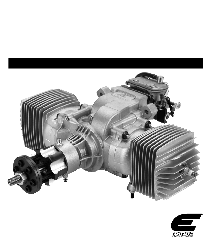
Evolution
152GX
USER GUIDE
®
Engines
Page 3

Table of Contents
Introduction ................................................................................................................................................... 3
Contents Included ......................................................................................................................................... 5
Mounting the Engine ..................................................................................................................................... 5
Throttle Linkage ............................................................................................................................................ 5
Choke Actuation ............................................................................................................................................ 5
Attaching the Fuel Lines ............................................................................................................................... 5
Spark Plug ..................................................................................................................................................... 5
Selecting a Suitable Propeller ..................................................................................................................... 5
Suggested Propeller Dimensions ................................................................................................................. 5
Control Jet System ......................................................................................................................................... 6
Ignition System Warning ............................................................................................................................... 7
Ignition Unit Power Source........................................................................................................................... 7
Warnings ........................................................................................................................................................ 7
Enabling or Disabling Battery Test ............................................................................................................... 8
Starting the Engine ........................................................................................................................................ 9
Starting the Engine Continued ...................................................................................................................10
Carburetor Adjustment ............................................................................................................................... 10
Troubleshooting Guide ................................................................................................................................ 11
152GX Evolution Engine Dimensions ........................................................................................................ 12
152GX Evolution Engine Specifications .................................................................................................... 12
Evolution Engines Auto-Choke Ignition System ........................................................................................ 12
Installation of the Auto-Choke Ignition Unit ............................................................................................. 13
Ignition Unit Wiring ...................................................................................................................................... 14
Programming Auto-Choke Ignition System and Pre-Ignition Curve ...................................................... 14
152GX Parts Diagram .................................................................................................................................. 15
152GX Parts List .......................................................................................................................................... 16
Introduction
Congratula tions on yo ur purchase of one of the newe st and most technically advanced 2- stroke ga s model air plane engines in
the world. Whether you are new to the sport of model aviation or an experienced pilot, you will enjoy the features of the new Evolution® GX engine.
Evolution engines are designed to be the most powerful in their class, extremely easy to start and operate, and provide years of enjoyable service.
This user’s guide is intended to provide the basic information required to operate and maintain your Evolution GX engine.
Important: While the Evolution engine is extremely easy to operate, if this is your first experience flying a model airplane, it is highly recommended that you have the help of an
experienced modeler during the first few flights. Your local hobby store or flying club can put you in touch with an experienced pilot in your area.
3
Page 4

Warranty Period
Exclusive Warranty- Horizon Hobby, Inc., (Horizon) warranties that the
Products purchased (the “Product”) will be free from defects in
materials and workmanship for a period of 2 years from the date of
purchase by the Purchaser.
Limited Warranty
(a) This warranty is limited to the original Purchaser (“Purchaser”) and
is not transferable. REPAIR OR REPLACEMENT AS PROVIDED UNDER
THIS WARRANTY IS THE EXCLUSIVE REMEDY OF THE PURCHASER. This
warranty covers only those Products purchased from an authorized
Horizon dealer. Third party transactions are not covered by this warranty.
Proof of purchase is required for warranty claims. Further, Horizon
reserves the right to change or modify this warranty without notice and
disclaims all other warranties, express or implied.
(b) Limitations- HORIZON MAKES NO WARRANTY OR REPRESENTATION,
EXPRESS OR IMPLIED, ABOUT NON-INFRINGEMENT, MERCHANTABILITY
OR FITNESS FOR A PARTICULAR PURPOSE OF THE PRODUCT. THE
PURCHASER ACKNOWLEDGES THAT THEY ALONE HAVE DETERMINED
THAT THE PRODUCT WILL SUITABLY MEET THE REQUIREMENTS OF THE
PURCHASER’S INTENDED USE.
(c) Purchaser Remedy- Horizon’s sole obligation hereunder shall be
that Horizon will, at its option, (i) repair or (ii) replace, any Product
determined by Horizon to be defective. In the event of a defect, these
are the Purchaser’s exclusive remedies. Horizon reserves the right to
inspect any and all equipment involved in a warranty claim. Repair
or replacement decisions are at the sole discretion of Horizon. This
warranty does not cover cosmetic damage or damage due to acts
of God, accident, misuse, abuse, negligence, commercial use, or
modification of or to any part of the Product. This warranty does not
cover damage due to improper installation, operation, maintenance,
or attempted repair by anyone other than Horizon. Return of any
goods by Purchaser must be approved in writing by Horizon before
shipment.
Damage Limits
HORIZON SHALL NOT BE LIABLE FOR SPECIAL, INDIRECT OR
CONSEQUENTIAL DAMAGES, LOSS OF PROFITS OR PRODUCTION OR
COMMERCIAL LOSS IN ANY WAY CONNECTED WITH THE PRODUCT,
WHETHER SUCH CLAIM IS BASED IN CONTRACT, WARRANTY,
NEGLIGENCE, OR STRICT LIABILITY. Further, in no event shall the liability
of Horizon exceed the individual price of the Product on which liability
is asserted. As Horizon has no control over use, setup, final assembly,
modification or misuse, no liability shall be assumed nor accepted for
any resulting damage or injury. By the act of use, setup or assembly, the
user accepts all resulting liability. If you as the Purchaser or user are not
prepared to accept the liability associated with the use of this Product,
you are advised to return this Product immediately in new and unused
condition to the place of purchase.
LAW: These Terms are governed by Illinois law (without regard to conflict
of law principals).
Safety Precautions
This is a sophisticated hobby Product and not a toy. It must be operated
with caution and common sense and requires some basic mechanical
ability. Failure to operate this Product in a safe and responsible manner
could result in injury or damage to the Product or other property. This
Product is not intended for use by children without direct adult
supervision. The Product manual contains instructions for safety,
operation and maintenance. It is essential to read and follow all the
instructions and warnings in the manual, prior to assembly, setup or
use, in order to operate correctly and avoid damage or injury.
Questions, Assistance, and Repairs
Your local hobby store and/or place of purchase cannot provide
warranty support or repair. Once assembly, setup or use of the
Product has been started, you must contact Horizon directly. This
will enable Horizon to better answer your questions and service you
in the event that you may need any assistance.
For questions or assistance, please direct your email to
productsupport@horizonhobby.com, or call 877.504.0233 toll free
to speak to a service technician.
Inspection or Repairs
If this Product needs to be inspected or repaired, please call for
a Return Merchandise Authorization (RMA). Pack the Product
securely using a shipping carton. Please note that original boxes
may be included, but are not designed to withstand the rigors
of shipping without additional protection. Ship via a carrier that
provides tracking and insurance for lost or damaged parcels, as
Horizon is not responsible for merchandise until it arrives and is
accepted at our facility. A Service Repair Request is available at
www.horizonhobby.com on the “Support” tab. If you do not have
internet access, please include a letter with your complete name,
street address, email address and phone number where you can
be reached during business days, your RMA number, a list of the
included items, method of payment for any non-warranty expenses
and a brief summary of the problem. Your original sales receipt
must also be included for warranty consideration. Be sure your
name, address, and RMA number are clearly written on the outside
of the shipping carton.
Warranty Inspection and Repairs
TO RECEIVE WARRANTY SERVICE, YOU MUST INCLUDE YOUR ORIGINAL
SALES RECEIPT verifying the proof-of-purchase date. Provided warranty
conditions have been met, your Product will be repaired or replaced free
of charge. Repair or replacement decisions are at the sole discretion of
Horizon Hobby.
Non-Warranty Repairs
Should your repair not be covered by warranty, the repair will be
completed and payment will be required without notification or
estimate of the expense unless the expense exceeds 50% of the
retail purchase cost. By submitting the item for repair you are agreeing
to payment of the repair without notification. Repair estimates are
available upon request. You must include this request with your repair.
Non-warranty repair estimates will be billed a minimum of ½ hour of
labor. In addition you will be billed for return freight. Please advise us
of your preferred method of payment. Horizon accepts money orders
and cashiers checks, as well as Visa, MasterCard, American Express,
and Discover cards. If you choose to pay by credit card, please include
your credit card number and expiration date. Any repair left unpaid or
unclaimed after 90 days will be considered abandoned and will be
disposed of accordingly. Please note: non-warranty repair is only
available on electronics and model engines.
United States:
Electronics and engines requiring inspection or repair should be shipped
to the following address:
Horizon Service Center
4105 Fieldstone Road
Champaign, Illinois 61822
All other Products requiring warranty inspection or repair should be
shipped to the following address:
Horizon Product Support
4105 Fieldstone Road
Champaign, Illinois 61822
Please call 877-504-0233 or e-mail us at
productsupport@horizonhobby.com with any questions or concerns
regarding this product or warranty.
United Kingdom:
Electronics and engines requiring inspection or repair should be shipped
to the following address:
Horizon Hobby UK
Units 1-4 Ployters Rd
Staple Tye
Harlow, Essex
CM18 7NS
United Kingdom
Please call +44 (0) 1279 641 097 or e-mail us at
sales@horizonhobby.co.uk with any questions or concerns regarding this
product or warranty.
Germany:
Electronics and engines requiring inspection or repair should be shipped
to the following address:
Horizon Technischer Service
Hamburger Strasse 10
25335 Elmshorn
Germany
Please call +49 4121 46199 66 or e-mail us at
service@horizonhobby.de with any questions or concerns regarding this
product or warranty.
4
Page 5

Contents Included
152GX
Two-blade
Three-blade
30x12 32x10 32x12 32.5x1130x10
28.5x12 29x12
Engine
Spark Plug 2 pcs (EVO30013309)
Electronic Ignition (EVO3314BB)
Exhaust Gasket (EVO30070407)
Plug wrench
Spark plug cable spiral wrap
Break in oil
Instruction sheet
Decal sheet
Optional Items
Muffler (EVO30113410)
Gas Start Kit (EVO1002)
Evolution 2-cycle Synthetic Oil (EVOX1001Q)
Silencer system (EVO30114210E)
Evolution stand off all 116/152 (EVO3312)
Ignition battery 3-cell 2100mAh Li-Po (THP21003SPL)
Micro Digital Tachometer (HAN156)
Mounting the Engine
Most model airplane designs make provision for an engine mount. It
is extremely important that the engine mount be securely attached
to the airplane’s firewall and that the engine is securely attached to
the engine mount. Follow the instructions included with the airplane
for mounting the engine. The engine should be fastened in place to
the firewall with 4 screws. Use good quality 1/4-inch or 6mm screw,
blind nuts and lock washers. Position the throttle servo, lower than
the carburator, to allow for more linear movement of the throttle.
If you decide to fasten the engine using a flexible motor mount,
always choose parts with enough solidity and strength. Make sure
all screws are tightened and regularly check that they remain tight
and in good condition.
In most installations an engine standoff will be required. To install
the entire engine forward of the firewall, one minimum 3-inch
standoff is needed. We recommend the EVO3312 engine standoff
assembly (available separately).
Important: Air is necessary to cool the engine during operation. Make
sure that sufficient air circulation through the cowling is provided. As
a basic reference, the outlet area should be 3–5 times the area of the
inlet area to provide adequate cooling.
Throttle Linkage
Carefully attach the throttle linkage to the engine using a ball link
on the carburetor. The throttle arm will accommodate a 4/40 ball
link. Make sure that the linkage is free to operate from low throttle
5
to high throttle and confirm that the low throttle setting on the
transmitter closes the carburetor butterfly to the low idle position.
Adjust the length of the pushrod until full throttle opens the throttle
fully, while low-throttle (low trim) completely closes the butterfly.
Choke Actuation
The choke lever is not drilled to accomodate a linkage from the
factory. If you plan to use a servo to activate the choke, the lever
will need to be drilled. Set this up in a manner similar to the throttle
linkage.
Attaching the Fuel Lines
Use large gasoline-compatible fuel line in the fuel tank as well as
the supply line to the engine. Use 3/16 brass/copper fuel tubing to
plumb the fuel tank. Be sure that the clunk inlet hole is of sufficient
size to work with this size of large fuel tubing.
Fuel for the Evolution Gas Engine
The Evolution gas engine has been designed to run on a mixture of
high-quality 91 octane unleaded gasoline and synthetic oil intended
for racing 2-stroke gasoline engines. For the break-in period of the
new engine, mix the fuel in a ratio of 30 parts gasoline to 1 part
lubricant. After break-in, use a ratio of 40 parts gasoline to 1 part
lubricant.
Spark Plug
The Evolution 152GX engine uses a CM-6 type of spark plug. Before
installing the spark plug you will need to set the spark plug gap to
the following dimension: .024 in to .028 in (.6mm to .7mm).
Selecting a Suitable Propeller
The Evolution® 152GX has been designed to generate maximum
power at 5800–6300 rpm, according to the type of exhaust used. If
you wish to utilize the maximum power output, choose a propeller,
which will allow the engine to reach these revolutions, or slightly
lower revolutions. (The engine will unload in the air, depending on
the aircraft speed and propeller selected.)
Suggested Propeller Dimensions
We do not recommend using propellers that allow the engine to
reach more than 7500 rpm on the ground.
Page 6

Control Jet System
Your engine is equipped with a unique system enabling improved acceleration from idle to high speed. This system allows the mixture to be
controlled while the throttle valve is opening. It will lean the mixture at low rpm and at idle. Conversely the mixture will become richer as the
throttle is opening. This system provides better acceleration to high speed and maintains a stable idle.
This system was developed for the Evolution 152cc engine. It is recommended that you do not change the mixture control leverage.
Idle
High Throttle
6
Page 7

Ignition System Warning
The GX electronic ignition fires the spark plugs for 1 second to check
the condition of the battery prior to starting the engine. If the engine
is in the compression position (i.e., the piston is above the exhaust
port in either the up OR down part of the stroke), any compressed
fumes may ignite, causing the propeller to turn and possibly the
engine to start unintentionally.
Bottom Dead Center can be found by rotating the propeller through
the compression stroke. As you rotate the propeller you will feel it
tighten, then suddenly loosen. Once the turn becomes very easy you
have completed the compression stroke and are at BDC. Once you
are sure the piston is in this position, you may turn on the ignition
power switch and operate the system safely.
To prevent this with the Evolution Gasoline GX Ignition System, the
Ignition Power Switch must be turned off; check to see that the
piston is in the bottom dead center (BDC) position.
As always, it is important to use extreme caution when near or
working with engines, fuel and propellers. If you have any
questions or concerns, please contact the Horizon Support Team at
1-877-504-0233 or productsupport@horizonhobby.com.
Ignition Unit Power Source
The Evolution 152GX ignition system was designed around a 3S 11.1-volt Li-Po battery pack. The system will operate from a minimum
of 9 volts to a maximum of 13 volts. In the event that the engine is in an inactive state for 90 seconds, the ignition unit goes into Fail-safe
and automatically turns off the ignition battery source. In order to power the ignition system back up, cycle the ignition power switch from Off
to On.
Warnings
Always do a range check with the engine running before the first flight. Use the ignition only in dry conditions. Use recommended number and type of cells for each ignition type. This
product is specified for RC engines only. Do not remove the resister cover if the ignition is on.
WARNING: REVERSAL OF POLES ON WIRE TO BATTERY WILL DESTROY THE IGNITION.
WARNING: DANGER OF ELECTRIC SHOCK (VOLTAGE OVER 20,000V).
WARNING: The manufacturer is not responsible for damages caused by not following the manual and/or use with anything other than RC engines.
WARNING: Because of possible interference, ignition and accumulators should be placed at least 25 cm from the receiver.
CAUTION: Use a standard servo with a current draw of less than 1.5A to operate the choke. Servos with a current draw greater than 1.5A, such as micro servos, digital servos and high-
torque servos, consume more current than the ignition system's circuitry is designed to provide. If the servo you've connected quivers or won't work at all, its current draw is probably
too high.
7
Page 8

Enabling or Disabling Battery Test
This ignition makes it possible to enable or disable the battery test. The battery test is very useful when Li-Po or Li-Ion batteries are used.
During the test, a series of flashes are generated and voltage is measured. When the battery passes the test, that means it will run for a
minimum of 10 minutes in flight.
- Battery test is disabled when jumper is removed and programming
pins are open (this is the default condition of the engine as
shipped from Evolution)
- Battery test is enabled when jumper is plugged in and
programming pins are closed
WARINING: The ignition system performs a self test when turning
on the ignitions switch. During the self test the spark plugs are
energized for a single spark. DO NOT HAVE THE ENGINE POSITIONED
BATTERY TEST ENABLED:
- close programming pins with
enclosed jumper
ON COMPRESSION STROKE WHEN TURNING ON THE IGNITION
SWITCH. It is possible for combustion to occur and the prop to start
rotating when turning the ignition switch on. Be sure to restrain the
aircraft prior to turning the ignition on when using the battery test
feature.
- Enable or disable battery test when the ignition is off
If you want to change the type of silencer, do the first two steps and then continue to PROGRAMMING SEQUENCE. Otherwise, follow these
steps:
BATTERY TEST DISABLED:
- open programming pins
(remove jumper)
FIRST STEP
- Screw pickup on engine
- Attach the plastic protection to the highvoltage cable
- Connect boot to plug
- Mount ground terminal on the high-voltage
cable bolt holding the engine to the motor
mount
- Mount the ignition to the airplane
SECOND STEP
- Connect enclosed LED to the ignition (red or
red/black wire to left)
START
- Keep clear of the propeller
- Connect battery with the ignition box
Starting Sequence
- Move propeller to put the piston at bottom dead center of its travel
- Keep your hands outside of the propeller radius to avoid serious injury
- Hold the airplane and switch on ignition
- If battery test is enabled, the ignition starts battery test; during this test, a series of sparks are
generated for about 2 seconds and LED is blinking
- If battery test is disabled, then LED blinks for about 2 seconds
- If LED turns off, you can fly; otherwise battery is low
8
Page 9

Starting the Engine
Starting the engine by using your hand or fingers can lead to a
serious injury. We recommend that you use a rubber stick to start
the engine.
The new Evolution Engine carburetor comes adjusted to a
basic setting. This setting should be maintained during the
initial break-in runs.
Before you first start the engine, make sure that the spark
plug is screwed in and tightened and that the plug socket
is fitted in place and fastened down properly. Fix the ignition
sensor in the proper position above the magnet with the
screws enclosed. Follow the directions in the Ignition System
addendum on page 8 to mount the ignition module in your model.
Important: Never turn the engine over with the ignition
turned on unless the spark plug is inserted in the plug socket.
This could lead to ignition damage.
Adjust Needle L
Adjust Needle H
Basic Setting - Throttle Closed
Carburetor Adjustments 152GX
Basic initial settings:
Adjust needle (L) for low rpm range 50 minutes
Adjust needle (H) for high rpm 1 turn
NOTE: The Low Speed adjustment is to the left of the high speed needle.
Starting and Choke Valve Operation
1) When you are ready to start your engine, make sure that the ignition is
switched off, the choke valve is closed and the throttle valve is partly open.
Confirm that fuel is filling the fuel line to the carburetor, then switch the
ignition to the ON position. Flip the propeller smartly until the engine fires.
With the choke in the closed position, the engine will fire then quit.
2) Open the choke valve and set the throttle at a slightly high idle position. Be
sure to have a helper hold the model securely. Give the propeller a few quick
flips. When the engine starts, allow it to idle for 30 to 45 seconds in order
for it to warm up to operating temperature. At this point, you can proceed
to test the carburetor settings before flying your model. See the following
section regarding carburetor adjustment.
9
3) If the engine does not start, leave the throttle at the high idle position,
turn the ignition off, then on and close the choke valve. Start the engine
with the throttle at the fast idle position and the choke valve closed. The
engine should fire and quit. If it does, repeat step 2 above.
4) At this point, if the engine still will not start, unscrew the spark plugs
and check the contacts. Clean any possible excess fuel (an indication of
engine flooding) and screw them in again. Further starting should only be
done with the throttle at idle position and the choke in the open position.
If the plug is dry, then probably not enough fuel has been drawn into the
carburetor. If that is the case, check for proper fuel feed and then return to
the instructions given in paragraph 1.
Page 10

Starting the Engine Continued
Having started the engine, leave it running for about 5 minutes at a higher idle speed. Then run it for about 20 minutes, while changing
revolutions from idle to 1/2–3/4 of the range and shortly holding each position—gradually prolonging the holding periods. After 10 minutes
of operation, open the throttle to maximum for a period of about one minute. At this point, stop the engine and let it cool down. Then restart it
and check the adjustment. If everything is all right, you can make your first flight. During the first few flights, do not overload the engine and
do not let it run at high revolutions for long periods of time (very important during hot weather). Use up all the fuel that was mixed with the oil
that is included with your engine. From then on, fuel and oil should be mixed in the proportion 40:1.
Carburetor Adjustment
First, start and warm the engine for 30 to 45 seconds before attempting to adjust the carburetor. In order to confirm that your engine is
properly adjusted you should follow the procedure below.
1) Move the throttle from idle to 2/3 of the full throttle position quickly (fast acceleration). Then repeat three times – if the engine accelerates
smoothly, go to step 3 below. If acceleration is not smooth, go on to step 2.
2) Faulty acceleration and a tendency to quit is usually attributable to a poor fuel mixture in the medium rpm range. Stop the engine and
recheck the fuel feed (the fuel line must not be pinched or broken). Restart the engine and test acceleration again. If the problem persists,
adjust the carburetor. Open the low speed needle by 1/8 turn and retest. If acceleration is smooth, open the needle by another 1/8 turn—this
should be done because the needle was previously set too lean; if atmospheric conditions have changed recently you may have to readjust
the needle. If the engine continues to not accelerate properly, open the low speed needle by 10 minutes. If the engine’s operation does not
improve, shut it off and check the basic setting, restart the engine and test the acceleration. If the engine runs correctly, go to step 3. If
it continues to not accelerate properly, open the low speed needle by another 10 minutes. If acceleration is faulty, the defect is likely to lie
somewhere other than an incorrect adjustment.
3) If the engine accelerates correctly, according to the above test, set it at idle speed and accelerate to full speed. Repeat twice more. If the
engine functions correctly, go to step 4. If it cuts out, open the low speed needle by another 1/8 turn.
4) If the engine reacts correctly, set it at full speed. If revolutions do not drop, the engine has been adjusted successfully. If revolutions seem
to drop, open the high-speed needle by approximately 5 to 10 minutes.
Caution! The engine must be stopped while you adjust the carburetor in order to prevent injury by the propeller.
10
Page 11

Troubleshooting Guide
If the engine does not start:
- Check and use a new spark plug if needed.
(Check the spark: put the plug into the cable end and by turning
the engine you´ll see the necessary spark. Note: The plug must
touch a metal part of the engine.)
- Check fuel lines.
- Check for proper mechanical function by turning the
engine over.
- Check that the carburetor is correctly installed.
- Remove the carburetor cover from the feed side; check
the filter and blow off carburetor with compressed air
(Caution: When using compressed air, use eye protection.);
when re-assembling be
the components.
- Check the vacuum feed line.
Mechanical Faults
If the engine cannot be turned over easily:
- The piston in the cylinder may be seized: loosen and unscrew
the cylinder bolts.
- Carefully remove the cylinder.
- Visually examine the piston and crankcase to find the likely cause
of the engine’s mechanical problem.
NOTE: Mechanical repairs must always be completed by our
professional service department.
careful to maintain the proper order of
Replacing the reed valve:
– Loosen carb screws and remove the carburetor (be careful to not
damage the gasket).
– Loosen four M4 screws on the flange, remove the flange and take
off the reed valve (be careful to not damage the gasket).
– Loosen four M2 screws and remove the old valves, replace them
with new ones, replace all screws and tighten gently.
– Be sure the gaskets are in their proper places.
11
Page 12

152GX Evolution Engine Dimensions
A B C D E
170mm 140mm 75mm 90mm 90mm
F G H I J K
6.6mm M10x1 55mm 234mm 25mm 288mm
152GX Evolution Engine Specifications
Bore
Stroke
Displacement
Weight without ignition*
Weight of ignition unit
RPM range
* The value in the table above stands for the weight of a completely assembled engine, including the spark plug, carburetor, drive washer and prop screws.
48mm
42mm
152cc / 9.3 cu in
3530 g / 7.8lb
210 g / 7.4 oz
1000–7500 rpm
Fuel
Lubrication / Break in
Lubrication / Standard
Unleaded 91-octane
Oil with gasoline
in mixture 1:30
Oil with gasoline
in mixture 1:40
Evolution Engines Auto-Choke Ignition System
The spark ignition included with your Evolution gas engine is a modern generation electronic ignition. There are many useful functions built
into the microprocessor of this unit.
In addition to the basic ignition functions, the unit has a FAIL-SAFE feature: After 90 seconds of inactivity, it automatically switches to an
inactive state. In order to restart normal operation, it is necessary to turn the battery switch off and then back on. This function will preserve
battery life should the switch be left in the ON position during inactivity.
12
Page 13

Installation of the Auto-Choke Ignition Unit
Technical Data
* if batter y test is enabled
Version
210 gWeight
3x Li-Ion/Li-Po* 11.1VPower supply
9x Ni-Cd / Ni-MH* 9–13V
9V*Minimal battery voltage*
13V *Maximum battery voltage*
Sleep mode after 90 seconds of engine inactivity
Battery level signalization *
Ignition goes off if engine runs counterclockwise
Choice of preignition curve
5ºPreignition point
240º / 120ºLocation of the magnet
1AhMin batter y capacity
Never use ignition wit h plug cap rem oved from plug! Befo re first
fligh t, do a range check wit h running en gine.
While installing the ignition unit in your model, be careful to have all parts that are connected to the unit and the engine situated as far
as practical from the radio receiver and radio antenna. The throttle servo should be mounted a distance of 8–12 inches from the engine.
The spark plug cable must not touch any part of the model structure as vibration may damage the cable. If this is not practical, it will be
necessary to provide an insulation material for the cable. Secure the ignition unit to the airframe using the provided hardware. Install the
bolts through the three rubber grommets and tighten securely. The grommets help to dampen the ignition unit from vibration. DO NOT
HARD MOUNT. Your Evolution ignition module has steel braided spark plug leads with grounding straps. Attach the grounding strap lead to
a cylinder base bolt or suitable place on the engine, and push the spark plug cap firmly on the spark plug. Install the spiral wrap spark plug
lead covering to protect the plug lead steel braiding from any possible chafing.
2
3
1
1
Ignition
2
LED
3
Programming cable
4
Power cable
4
ICU–B Min 9V
Max 13V
LED Blinking Patterns
13
C onnect LED indicator to the ignition
box (red/black wire to “+”).
LED
U sing the included connector, plug your
battery pack into the ignition box.
F ive seconds after connecting the
battery, the LED indicator should go
out. If the LED is blinking after you
connect the battery, the battery’s
voltage is too low.
Page 14

Ignition Unit Wiring
The Evolution 152GX ignition system has an incorporated automatic choke feature. The automatic choke feature will require the installation
of a choke servo connected to the choke lever via pushrod. The choke lever is not drilled to accommodate hardware from the factory but it is
simple to drill and add a ball link to the lever.
Programming of the automatic choke feature is required through a simple process. Look to the programming chart for the wiring and
programming process. There is a slightly different program procedure, depending on what type of exhaust system is installed on the engine.
If the automatic choke feature is not desired, omit the ignition programming steps and use a manual choke mechanism. The ignition
programming LED can still be used as an onboard ignition battery pack status light.
Programming Auto-Choke Ignition System and Pre-Ignition Curve
1
2
3
1
5
6
7
4
8
9
Ignition
2
LED
3
Programming cable
4
Ignition battery (6-cell)
3 cell Li-Po 9 cell Ni-cd or Ni-MH
5
Transmitter
6
Receiver
7
Receiver battery
8
Servo
9
Power cable
D isconnect the ignition system’s
battery.
C onnect the LED indicator.
C onnect the throttle potentiometer
outlet to the throttle channel on your
receiver.
C onnect the auto-choke servo to
the ignition box (black or brown to
“–” pin).
S witch on your transmitter.
C onnect receiver battery with the
receiver.
C onnect ignition battery to the ignition.
PROG SERVO
Long Silencer Choke Settings
(Canister or Tuned Pipe)
1) Using the throttle stick, close the choke
until it closes completely. Wait until the
LED blinks once, indicating the ignition has
memorized the “closed choke” position.
2) Using the throttle stick, open the choke
valve until it is all the way open.
Wait until the LED blinks once, indicating the ignition unit has memorized
the “choke open” position.
3) Leave the choke open for an additional 5
seconds, and the LED will blink rapidly,
indicating that the Long Silencer
Pre-ignition program has been set.
4) Disconnect the receiver.
Short Silencer Choke Settings
(Pitts Style)
1) Using the throttle stick, close the choke
until it closes completely. Wait until the LED
blinks once, indicating the ignition has
memorized the “closed choke” position.
2) Using the throttle stick, open the choke
valve until it is all the way open.
Wait until the LED blinks once, indicating the ignition unit has memorized
the “choke open” position.
3) Move the choke to the closed position and
hold there for an additional 5 seconds; the
LED will blink slowly, indicating that the Short
Silencer Pre-ignition program has been set.
4) Disconnect the receiver.
14
Page 15

152GX Parts Diagram
15
Page 16

EVO30100102 Crankcase Screws Set
EVO30100202 Front Bearing
EVO30100204 Packing
EVO30070203 Rear Bearing
EVO30940304 Pressure Nozzle
EVO30940305 Pressure Nozzle Gasket
EVO30010402 Cylinder Screws Set*
EVO30010403 Cylinder Nut*
EVO30070404 Cylinder Gasket*
EVO30010405 Exhaust Screws Set*
EVO30010406 Exhaust Nut*
EVO30070407 Exhaust Flange Gasket*
EVO30070701 Piston*
EVO30070702
Piston Ring*
EVO30070801 Piston Pin*
EVO30070802 Piston Pin Retainer*
EVO30100205
Rear Needle Bearing
EVO30100104
Spacer Sleeve
EVO30110101 Crankcase
EVO30110401 Cylinder*
EVO30111001
Crankshaft Assembly
EVO30010308 Carburetor Flange Screws Set
EVO30013309 Spark Plug
EVO30941405
Ignition Sensor Fixing Screws
EVO3010i1101 Drive Washer
EVO30101102 Drive Washer Key
EVO30011103
Propeller Nut
EVO30101104 Propeller Washer
EVO30101105 Propeller Screw
EVO30101107 Propeller Screws Set
EVO30100306 Carburetor Flange
EVO30100307 Carburetor Flange Gasket
EVO30101301 Reed Valve Case
EVO30101302 Reed Valve
EVO30101303 Reed Valve Screws
EVO30101304 Reed Valve Gasket (Upper)
EVO30101305 Reed Valve Gasket (Lower)
EVO30101306 Reed Valve Strap
EVO30101307 Carburetor Screws
EVO3314BB Electric Ignition Type 2, ICU-B
EVO30101300 Reed Valve Assembly
EVO3228 Carburetor Complete
Part Number Description Part Number Description
* Requires a quantity of 2
152GX Parts List
16
 Loading...