

Page 1

Original Instructions
Originalbetriebsanleitung
Notice Originale
Instrucciones Originales
Oryginalna Instrukcja
Instruções Originais
Instrucțiuni Iniţiale
Оригинальные Инструкции
Orijinal Talimatlar
026-0001,
026-0002,
026-0003
027-0001,
027-0002,
027-0003
GB2438285
Original written in UK English Date Published: 01 / 06 / 2018
027-0001C, 027-0002C,
027-0003C, 027-0004,
027-0006, 027-0010
027-0001A, 027-0002A,
027-0003A, 027-0004A,
027-0006A
Page 2

www.evolutionpowertools.com
TABLE OF CONTENTS
INTRODUCTION
Warranty Page 3
Specifications Page 4
Items Supplied Page 4
Vibration Page 4
Labels And Symbols Page 6
Intended Use Of This Power Tool Page 7
Prohibited Use Of This Power Tool Page 7
SAFETY PRECAUTIONS
Electrical Safety Page 7
Outdoor Use Page 7
General Power Tool Safety
Instructions
Health Advice Page 9
Safety Instructions For All Saws Page 9
Additional Safety Instructions For
Circular Saws
GETTING STARTED
Unpacking Page 11
Machine Overview Page 12
Preparation Page 21
Installing/Removing A Blade Page 21
Parallel Edge Guide Page 22
Cutting Depth Adjustment Page 22
Cutting Angle Adjustment Page 22
Operating Advice
(Pre Operation Checks)
PPE Page 23
The On/Off Trigger Switch Page 23
Cutting Tracks Page 24
Page 7
Page 11
Page 22
MAINTENANCE &
ADJUSTMENTS
Checking & Replacing Carbon
Brushes
General Maintenance & Cleaning Page 29
Environmental Protection Page 29
DECLARATION OF
CONFORMITY
Page 28
Page 29
Page 30
ADDITIONAL ADVICE
Debris Collection Port Page 26
Led Light Page 26
Specialised Adjustments Page 27
General Cutting Advice Page 27
Cut Material Ejection Port Page 28
2
Page 3

www.evolutionpowertools.com
DE
EN
FR
ES
(1.2) INTRODUCTION
IMPORTANT
Please read these operating and safety instructions
carefully and completely.
For your own safety, if you are uncertain about any
aspect of using this equipment please access the relevant
Technical Helpline, the number of which can be found on
the Evolution Power Tools website. We operate several
Helplines throughout our worldwide organization, but
Technical help is also available from your supplier.
(1.3) CONTACT:
Web: www.evolutionpowertools.com
UK/EU/AUS: customer.services@evolutionpowertools.com
USA: evolutioninfo@evolutionpowertools.com
(1.4) WARRANTY
Congratulations on your purchase of an Evolution Power
Tools Machine. Please complete your product registration
‘online’ as explained in the registration leaflet included
with this machine. This will enable you to validate your
machine’s warranty period via Evolutions website by
entering your details and thus ensure prompt service if
ever needed.
We sincerely thank you for selecting
a product from Evolution Power Tools.
3
Page 4

www.evolutionpowertools.com
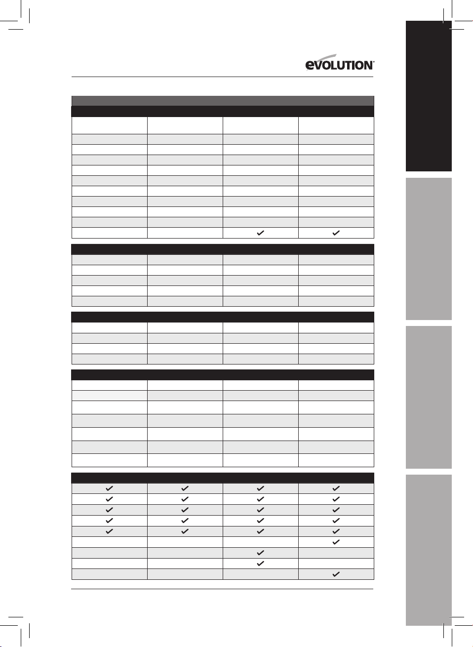
SPECIFICATIONS
USA
MACHINE SPECIFICATIONS R185CCS R185CCSX R185CCSX+
Model No:
0270004 0270004C 0270004A
Motor EU (220-240V ~ 50 Hz)
Motor UK (110V ~ 50 Hz)
Motor USA (120V ~ 60 Hz) 15A 15A 15A
No-Load Speed (220-240v)
No-Load Speed (110v & 120v) 3700 min
-1
/ rpm 3700 min
-1
/ rpm 3700 min
-1
/ rpm
Weight 10.8 lb 11.2 lb 11.2 lb
Max. Blade Bevel Angle (Degrees) 60˚ 45˚ 45˚
Power Cable Length 13 ft 13 ft 13 ft
Circular Saw Base Type Cast Aluminum Cast Aluminum Cast Aluminum
Cutting Track Compatible
CUTTING CAPACITIES R185CCS R185CCSX R185CCSX+
Mild Steel Plate (Max. Thickness) 1/4” 1/4” 1/4”
Mild Steel Box Section (Max. Wall) 1/4” 1/4” 1/4”
Max. Cutting Thickness (0°) 2-1/2” 2-1/2” (2-5/16” w/Track) 2-1/2” (2-5/16” w/Track)
Max. Cutting Thickness (45°) 1-9/16” 1-13/16” (1-5/8” w/Track) 1-13/16” (1-5/8” w/Track)
Max. Cutting Thickness (60°) 1”
BLADE SPECIFICATIONS R185CCS R185CCSX R185CCSX+
Blade Diameter Ø 7-1/4” Ø 7-1/4” Ø 7-1/4”
Number of Teeth 16 16 16
Bore Diameter 25/32” 25/32” 25/32”
Kerf 1.7mm 1.7mm 1.7mm
NOISE & VIBRATION DATA R185CCS R185CCSX R185CCSX+
Sound Pressure Level L
Sound Power Level L
Vibration - Main Handle (Sawing Wood)
Vibration - Auxiliary Handle (Sawing Wood)
Vibration - Main Handle (Sawing Metal)
Vibration - Auxiliary Handle (Sawing Metal)
pa
wa
Uncertainty K
94,3dB(A) K=3 dB(A) 94,3dB(A) K=3 dB(A) 94,3dB(A) K=3 dB(A)
105,3dB(A) K=3 dB(A) 105,3dB(A) K=3 dB(A) 105,3dB(A) K=3 dB(A)
A
= 3,347m/s
h,w
A
= 3,119m/s
h,w
a
= 3,572m/s
h,M
a
= 3,241m/s
h,M
1,5m/s
2
a
= 3,347m/s
2
2
2
2
h,w
a
= 3,119m/s
h,w
a
= 3,572m/s
h,M
a
= 3,241m/s
h,M
1,5m/s
2
a
= 3,347m/s
2
2
2
2
h,w
a
= 3,119m/s
h,w
a
= 3,572m/s
h,M
a
= 3,241m/s
h,M
1,5m/s
2
2
2
2
2
ITEMS SUPPLIED R185CCS R185CCSX R185CCSX+
Multi-Material TCT Blade
Hex Key (Blade Change)
Parallel Edge Guide
Dust Port Adapter
Dust Hose Connector
Carry Case
Cutting Track - 340mm (13-3/8”) x3
Connector Bar & Screws (x4)
LED Light
4
Page 5
www.evolutionpowertools.com
DE
EN
FR
ES
R165CCSL R185CCS R185CCSX R185CCSX+
0260001 / 0260002 /
0260003
1200W 1600W 1600W 1600W
1200W 1600W 1600W 1600W
UK / EU / AUS
0270001C /
0270002C / 0270003C
0270001 /
0270002 / 0270003
0270001A /
0270002A / 0270003A
-1
3700 min
/ rpm 3900 min
-1
3700 min
/ rpm 3700 min
-1
/ rpm 3900 min
-1
/ rpm 3700 min
-1
/ rpm 3900 min
-1
/ rpm 3700 min
-1
-1
/ rpm
/ rpm
4.3 kg 4.9 kg 5.1 kg 5.1 kg
45˚ 60˚ 45˚ 45˚
3m 3m 3m 4m
Pressed Steel Cast Aluminium Cast Aluminium Cast Aluminium
R165CCSL R185CCS R185CCSX R185CCSX+
3mm 6mm 3mm 6mm
3mm 6mm 3mm 6mm
53mm 64mm 64mm (59mm w/Track) 64mm (59mm w/Track)
34mm 40mm 47mm (42mm w/Track) 47mm (42mm w/Track)
24mm
R165CCSL R185CCS R185CCSX R185CCSX+
Ø 165mm Ø 185mm Ø 185mm Ø 185mm
14 20 16 20
20mm 20mm 20mm 20mm
1.7mm 1.7mm 1.7mm 1.7mm
R165CCSL R185CCS R185CCSX R185CCSX+
92,4dB(A) K:3dB(A) 94,3dB(A) K=3 dB(A) 94,3dB(A) K=3 dB(A) 94,3dB(A) K=3 dB(A)
103,4dB(A) K:3dB(A) 105,3dB(A) K=3 dB(A) 105,3dB(A) K=3 dB(A) 105,3dB(A) K=3 dB(A)
a
= 2,747m/s2 a
h,w
a
= 2,619m/s
h,w
a
= 2,302m/s
h,M
a
= 2,239m/s
h,M
1,5m/s
2
2
2
2
= 3,347m/s
h,w
a
= 3,119m/s
h,w
a
= 3,572m/s
h,M
a
= 3,241m/s
h,M
1,5m/s
2
2
2
2
2
a
h,w
a
h,w
a
h,M
a
h,M
= 3,347m/s
= 3,119m/s
= 3,572m/s
= 3,241m/s
2
1,5m/s
2
2
2
2
a
= 3,347m/s
h,w
a
= 3,119m/s
h,w
a
= 3,572m/s
h,M
a
= 3,241m/s
h,M
1,5m/s
2
2
2
2
2
R165CCSL R185CCS R185CCSX R185CCSX+
5
Page 6
www.evolutionpowertools.com
VIBRATION
(1.5) Note: The vibration measurement
was made under standard conditions in
accordance with: EN 62841-1: 2015,
EN 62841-2-5: 2014
Warning: Wear hearing protection!
The declared vibration total value has been
measured in accordance with a standard test
method and may be used for comparing one
tool with another.
The declared vibration total value may also be
used in a preliminary assessment of exposure.
(1.6) WARNING: When using this machine
the operator can be exposed to high levels of
vibration transmitted to the hand and arm.
It is possible that the operator could develop
“Vibration white finger disease” (Raynaud
syndrome). This condition can reduce the
sensitivity of the hand to temperature as
well as producing general numbness.
Prolonged or regular users of this machine
should monitor the condition of their hands
and fingers closely. If any of the symptoms
become evident, seek immediate
medical advice.
• The measurement and assessment of
human exposure to hand-transmitted
vibration in the workplace is given in:
EN 62841-1 and EN 62841-2-5
• Many factors can influence the actual
vibration level during operation e.g. the
work surfaces condition and orientation
and the type and condition of the machine
being used. Before each use, such factors
should be assessed, and where possible
appropriate working practices adopted.
Managing these factors can help reduce
the effects of vibration:
Handling
• Handle the machine with care,
allowing the machine to do the work.
• Avoid using excessive physical effort on any
of the machines controls.
• Consider your security and stability, and the
orientation of the machine during use.
Work Surface
• Consider the work surface material;
its condition, density, strength,
rigidity and orientation.
WARNING: The vibration emission during
actual use of the power tool can differ from
the declared total value depending on the
ways in which the tool is used.
The need to identify safety measures
and to protect the operator are based on
an estimation of exposure in the actual
conditions of use (taking account of all parts
of the operating cycle, such as the times the
tool is switched off, when it is running idle,
in addition to trigger time).
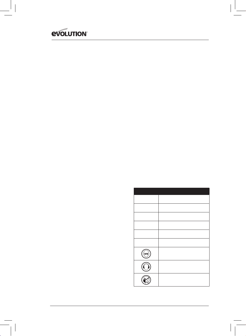
(1.7 ) LABELS & SYMBOLS
WARNING: Do not operate this machine
if warning and/or instruction labels are
missing or damaged. Contact Evolution
Power Tools for replacement labels.
Note: All or some of the following symbols
may appear in the manual or on the product.
(1.8)
Symbol Description
V
A
Hz
Min-1 / RPM
~
n
o
Volts
Amperes
Hertz
Speed
Alternating Current
No Load Speed
Wear Safety Goggles
Wear Ear Protection
Wear Dust Protection
6
Page 7
www.evolutionpowertools.com
DE
EN
FR
ES
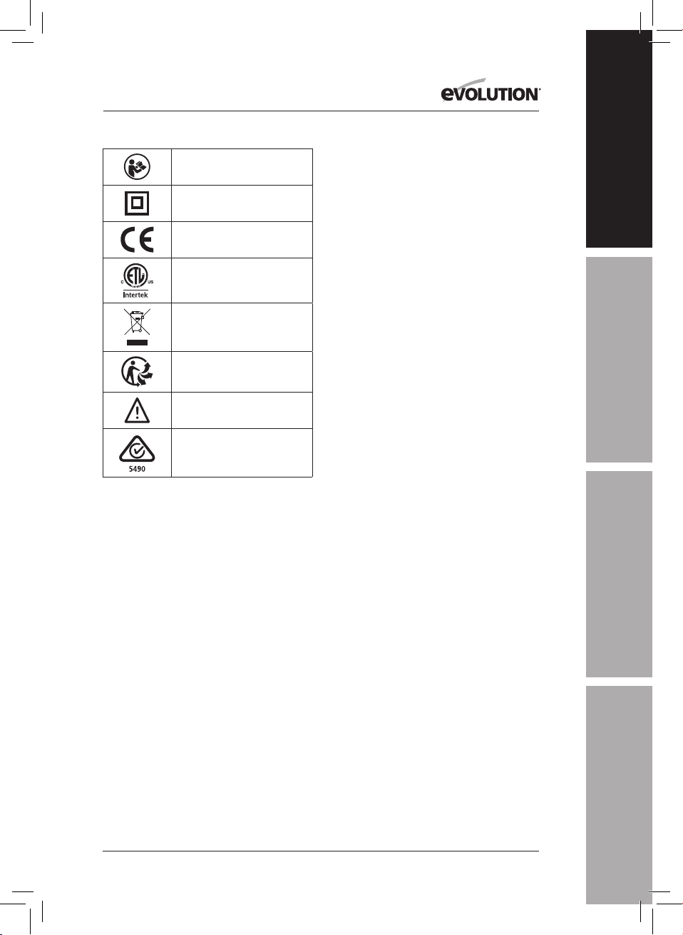
Read Instructions
Double Insulated
CE Certification
ETL Certification
Waste Electrical &
Electronic Equipment
Triman - Waste Collection
& Recycling
Warning
(RCM) Regulatory Compliance Mark
for electrical and electronic equipment.
Australian/New Zealand Standard
(1.9)
INTENDED USE
OF THIS POWER TOOL
WARNING: This product is a Hand Operated
Circular Saw and has been designed to be
used with special Evolution blades. Only use
accessories designed for use in this machine
and/or those recommended specifically
by Evolution Power Tools Ltd.
When fitted with an appropriate blade
this machine can be used to cut:
Mild Steel, Aluminium, Wood
Note: Cutting galvanised steel may reduce
blade life.
(1.10) PROHIBITED USE
OF THIS POWER TOOL
WARNING: This product is a Hand Operated
Circular Saw and must only be used as such.
It must not be modified in any way, or used to
power any other equipment or drive any other
accessories other than those mentioned in this
Instruction Manual.
(1.11) WARNING: This machine is not intended
for use by persons (including children) with
reduced physical, sensory
or mental capabilities, or lack of experience
and knowledge, unless they have been given
supervision or instruction concerning the safe
use of the machine by a person responsible
for their safety and who is competent
in its safe use.
Children should be supervised to ensure
that they do not have access to, and are
not allowed to play with, this machine.
(1.12) ELECTRICAL SAFETY
This machine is fitted with the correct
moulded plug and mains lead for the
designated market. If the supply cord is
damaged, it must be replaced by a special
cord or assembly available from the
manufacturers or its service agent.
(1.13) OUTDOOR USE
WARNING: For your protection if this tool is to
be used outdoors it should not be exposed to
rain, or used in damp locations. Do not place
the tool on damp surfaces. Use a clean, dry
workbench if available. For added protection
use a residual current device (R.C.D.) that will
interrupt the supply if the leakage current to
earth exceeds 30mA for 30ms. Always check
the operation of the residual current device
(R.C.D.) before using the machine.
If an extension cable is required it must be a
suitable type for use outdoors and so labelled.
The manufacturers instructions should be
followed when using an extension cable.
(2.1) GENERAL SAFETY
INSTRUCTIONS
(These General Power Tool Safety Instructions
are as specified in EN 62841-1: 2015).
WARNING: Read all safety warnings and
instructions. Failure to follow the warnings
and instructions may result in electric shock,
fire and/ or serious injury.
Save all warnings and instructions for
future reference. The term “power tool” in
7
Page 8

www.evolutionpowertools.com
the warnings refers to your mains-operated
(corded) power tool or battery-operated
(cordless) power tool.
(2.2) 1) General Power Tool
Safety Warnings [Work area safety]
a) Keep work area clean and well lit.
Cluttered or dark areas invite accidents.
b) Do not operate power tools in explosive
atmospheres, such as in the presence of
flammable liquids, gasses or dust. Power
tools create sparks which may ignite the
dust or fumes.
c) Keep children and bystanders away while
operating power tool. Distractions can cause
you to lose control.
(2.3) 2) General Power Tool Safety Warnings
[Electrical Safety]
a) Power tool plugs must match the outlet.
Never modify the plug in any way. Do
not use any adapter plugs with earthed
(grounded) power tools. Unmodified plugs
and matching outlets will reduce risk of
electric shock.
b) Avoid body contact with earthed or
grounded surfaces, such as pipes, radiators,
ranges and refrigerators. There is an
increased risk of electric shock if your body is
earthed or grounded.
c) Do not expose power tools to rain or wet
conditions. Water entering a power tool will
increase the risk of electric shock.
d) Do not abuse the cord. Never use the cord
for carrying, pulling or unplugging the power
tool. Keep cord away from heat, oil, sharp
edges or moving parts. Damaged or entangled
cords increase the risk of electric shock.
e) When operating a power tool outdoors,
use an extension cord suitable for outdoor
use. Use of a cord suitable for outdoor use
reduces the risk of electric shock.
f) If operating a power tool in a damp
location is unavoidable, use a residual
current device (RCD) protected supply.
Use of an RCD reduces the risk of
electric shock.
Note: The product is intended for use
only in premises having a service current
capacity≥100A per phase, supplied from a
distribution network having a nominal voltage
of 230V. If required, contact the electricity
company to ensure that the mains current
carrying capacity at the connection point
to the public power grid is adequate for
connecting the product.
(2.4) 3) General Power Tool Safety Warnings
[Personal Safety].
a) Stay alert, watch what you are doing and
use common sense when operating a power
tool. Do not use a power tool while you are
tired or under the influence of drugs, alcohol
or medication. A moment of inattention while
operating power tools may result in serious
personal injury.
b) Use personal protective equipment.
Always wear eye protection. Protective
equipment such as dust masks, non-skid safety
shoes, hard hat or hearing protection used
for appropriate conditions will reduce
personal injuries.
c) Prevent unintentional starting. Ensure the
switch is in the off-position before connecting
to power source and or battery pack, picking
up or carrying the tool. Carrying power tools
with your finger on the switch or energising the
power tools that have the switch on
invites accidents.
d) Remove any adjusting key or wrench
from blade bolt before turning the power
tool on. A wrench or key left attached to a
rotating part of a power tool may result in
personal injury.
e) Do not overreach. Keep proper footing and
balance at all times. This enables better control
of the power tool in unexpected situations.
f) Dress properly. Do not wear loose clothing
or jewellery. Keep your hair, clothing and gloves
away from moving parts. Loose clothes, jewellery
or long hair can be caught in moving par ts.
g) If devices are provided for the connection
of dust extraction and collection facilities,
ensure that these are connected and
properly used. Use of dust collection can
reduce dust-related hazards.
h) Do not let familiarity gained from
frequent use of tools allow you to become
complacent and ignore tool safety
principles. A careless action can cause severe
injury within a fraction of a second.
8
Page 9

www.evolutionpowertools.com
DE
EN
FR
ES
(2.5) 4) General Power Tool Safety Warnings
[Power tool use and care].
a) Do not force the power tool. Use the
correct power tool for your application. The
correct power tool will do the job better and
safer at a rate for which it was designed.
b) Do not use the power tool if the switch
does not turn it on or off. Any power tool
that cannot be controlled with the switch
is dangerous and must be repaired.
c) Disconnect the power tool from the
power source from the power tool before
making any adjustments, changing
accessories, or storing power tools. Such
preventative safety measures reduce the risk
of starting the power
tool accidentally.
d) Store idle power tools out of the reach
of children and do not allow persons
unfamiliar with the power tool or these
instructions to operate the power tool.
Power tools are dangerous in the hands of
untrained users.
e) Maintain power tools. Check for
misalignment or binding of moving parts,
breakage of moving parts and any other
condition that may affect the power tools
operation. If damaged, have the power tool
repaired before use. Many accidents are
caused by poorly maintained power tools.
f) Keep cutting tools sharp and clean.
Properly maintained cutting tools with
sharp cutting edges are less likely to bind
and are easier to control.
g) Use the power tool, accessories and
tool bits etc. in accordance with these
instructions, taking into account the
working conditions and the work to
be performed. Use of the power tool for
operations different from those intended
could result in a hazardous situation.
h) Keep handles and grasping surfaces dry,
clean and free from oil and grease. Slippery
handles and grasping surfaces do not allow
for safe handling and control of the tool in
unexpected situations.
(2.6) 5) General Power Tool
Safety Warnings [Service]
a) Have your power tool serviced by a
qualified repair person using only identical
replacement parts. This will ensure that the
safety of the power tool is maintained.
(2.7) HEALTH ADVICE
WARNING: When using this machine,
dust particles may be produced. In some
instances, depending on the materials you
are working with, this dust can be particularly
harmful. If you suspect that paint on the
surface of material you wish to cut contains
lead, seek professional advice. Lead based
paints should only be removed by
a professional and you should not
attempt to remove it yourself.
Once the dust has been deposited on
surfaces, hand to mouth contact can result
in the ingestion of lead. Exposure to even
low levels of lead can cause irreversible brain
and nervous system damage. The young and
unborn children are particularly vulnerable.
You are advised to consider the risks
associated with the materials you are working
with and to reduce the risk of exposure.
As some materials can produce dust that may
be hazardous to your health, we recommend
the use of an approved face mask with
replaceable filters when using this machine.
You should always:
• Work in a well-ventilated area.
• Work with approved safety equipment, such
as dust masks that are specially designed to
filter microscopic particles.
(2.8) WARNING: the operation of any power
tool can result in foreign objects being thrown
towards your eyes, which could result in
severe eye damage. Before beginning power
tool operation, always wear safety goggles
or safety glasses with side shield or a full face
shield where necessary.
SAFETY INSTRUCTIONS FOR ALL SAWS
[Cutting procedures]
a) DANGER: Keep hands away from cutting
area and the blade. Keep your second
hand on auxiliary handle, or motor
housing. If both hands are holding the saw,
they cannot be cut by the blade.
9
Page 10

www.evolutionpowertools.com
b) Do not reach underneath the workpiece.
The guard cannot protect you from the blade
below the workpiece.
c) Adjust the cutting depth to the thickness of
the workpiece. Less than a full tooth of the blade
teeth should be visible below the workpiece.
d) Never hold the workpiece in your hands
or across your leg while cutting. Secure
the workpiece to a stable platform. It is
important to support the work properly to
minimise body exposure, blade binding, or
loss of control.
e) Hold the power tool by insulated
gripping surfaces, when performing an
operation where the cutting tool may
contact hidden wiring or its own cord.
Contact with a “live” wire will also make
exposed metal parts of the power tool ‘live’
and could give the operator an electric shock.
f) When ripping, always use a rip fence
or straight edge guide. This improves the
accuracy of cut and reduces the chance of
blade binding.
g) Always use blades with correct size and
shape (diamond versus round) of arbour
holes. Blades that do not match the mounting
hardware of the saw will run off-centre,
causing loss of control.
h) Never use damaged or incorrect blade
washers or bolt. The blade washers and
bolt were specially designed for your saw, for
optimum performance and safety of operation.
(3.2) [Kickback causes and
related warnings]
Kickback is a sudden reaction to a pinched,
jammed or misaligned saw blade, causing
an uncontrolled saw to lift up and out of the
workpiece toward the operator;
When the blade is pinched or jammed tightly
by the kerf closing down, the blade stalls and
the motor reaction drives the unit rapidly back
toward the operator;
(3.3)
Kickback is the result of saw misuse and/or
incorrect operating procedures or conditions
and can be avoided by taking proper
precautions as given below.
a) Maintain a firm grip with both hands on
the saw and position your arms to resist
kickback forces. Position your body to
either side of the blade, but not in line
with the blade. Kickback could cause the
saw to jump backwards, but kickback forces
can be controlled by the operator, if proper
precautions are taken.
b) When blade is binding, or when
interrupting a cut for any reason, release
the trigger and hold the saw motionless
in the material until the blade comes to a
complete stop. Never attempt to remove the
saw from the work or pull the saw backward
while the blade is in motion or kickback may
occur. Investigate and take corrective actions
to eliminate the cause of blade binding.
c) When restarting a saw in the workpiece,
centre the saw blade in the kerf so that the saw
teeth are not engaged into the material. If a saw
blade binds, it may walk up or kickback from the
workpiece as the saw is restarted.
d) Do not use dull or damaged blades.
Unsharpened or improperly set blades produce
narrow kerf causing excessive friction, blade
binding and kickback.
e) Blade depth and bevel adjusting locking
levers must be tight and secure before making
a cut. If the blade adjustment shifts while cutting
it may cause binding and kickback.
f) Blade depth and bevel adjusting locking
levers must be tight and secure before
making the cut. If blade adjustment shifts
while cutting, it may cause binding and
kickback.
g) Use extra caution when sawing into
existing walls or other blind areas. The
protruding blade may cut objects that can
cause kickback.
If the blade becomes twisted or misaligned
in the cut, the teeth at the back edge of the
blade can dig into the top surface of the wood
causing the blade to climb out of the kerf and
jump back toward the operator.
LOWER GUARD FUNCTION
a) Check the lower guard for proper closing
before each use. Do not operate the saw if
the lower guard does not move freely and
close instantly. Never clamp or tie the lower
guard into the open position. If the saw is
10
Page 11

www.evolutionpowertools.com
DE
EN
FR
ES
accidentally dropped, the lower guard may be
bent. Raise the lower guard with the retracting
handle and make sure it moves freely and does
not touch the blade or any other part, in all
angles and depths of cut.
b) Check the operation of the lower guard
spring. If the guard and the spring are not
operating properly, they must be serviced
before use. Lower guard may operate
sluggishly due to damaged parts, gummy
deposits, or a build-up of debris.
c) The lower guard may be retracted
manually only for special cuts such as
“plunge cuts” and “compound cuts”.
Raise the lower guard by the retracting
handle and as soon as the blade enters the
material, the lower guard must be released.
For all other sawing, the lower guard should
operate automatically.
d) Always observe that the lower guard is
covering the blade before placing the saw
down on bench or floor. An unprotected,
coasting blade will cause the saw to walk
backwards, cutting whatever is in its path. Be
aware of the time it takes for the blade to stop
after switch is released.
ADDITIONAL SAFETY
INSTRUCTIONS
FOR CIRCULAR SAWS
a) Do not use High Speed Steel (HSS)
saw blades.
b) Inspect the machine and the blade
before each use. Do not use deformed,
cracked, worn or otherwise damaged blades.
c) Never use the saw without the original
guard protection system. Do not lock
the moving guard in the open position.
Ensure that the guard operates freely
without jamming.
d) Only use blades that comply with the
characteristics specified in this manual.
Before using accessories, always compare
the maximum allowed RPM of the
accessory with the RPM of the machine.
e) Do not use any abrasive wheels.
f) Use only blade diameter(s) in accordance
with the markings.
(3.4) WARNING: If any parts are missing, do
not operate your machine until the missing
parts are replaced. Failure to follow this rule
could result in serious personal injury.
(4.1) GETTING STARTED - UNPACKING
Caution: This packaging contains sharp objects.
Take care when unpacking. Remove the machine,
together with the accessories supplied from the
packaging. Check carefully to ensure that the
machine is in good condition and account for all
the accessories listed in this manual. Also make
sure that all the accessories are complete.
If any parts are found to be missing,
the machine and its accessories should be
returned together in their original packaging to
the retailer.
Do not throw the packaging away; keep it safe
throughout the warranty period. Dispose of the
packaging in an environmentally responsible
manner. Recycle if possible.
Do not let children play with empty plastic bags
due to the risk of suffocation.
(4.3) Evolution Instruction Manuals
Evolution Power Tools provides each product
with an Instruction Manual.
Each dedicated manual is carefully constructed
and designed to provide easily accessible and
useful information regarding the safe use, care
and maintenance of the product. Referencing
the information contained within the manual
will allow the operator to fully and safely
exploit the potential of the machine.
Evolutions policy of continual product
development may mean that, very
occasionally, the contents of a manual may not
completely reflect the latest improvements or
upgrades that have been incorporated into a
particular product. Upgrades/improvements
to the specification of a product could come
about as a consequence of technological
advances or changes to the legislative
framework of the receiving country, etc.
If you are at all unsure about any aspect of
the use, care or maintenance of an Evolution
product, contact the relevant Evolution
helpline where up to date information and
extra advice will be available.
11
Page 12

www.evolutionpowertools.com
USA
18
1
2
16
17
15
19
14
3
4
5
6
7
1. CUT MATERIAL EJECTION PORT
2. THUMB LEVER
3. MULTI-MATERIAL TCT BLADE
4. LOWER BLADE GUARD
5. PARALLEL EDGE GUIDE
6. ERGONOMIC FRONT HANDLE
7. CARBON BRUSHES
8. 5/16” HEX KEY (BLADE CHANGE)
9. DEPTH ADJUSTMENT LOCKING LEVER
10. DEPTH SCALE
11. REAR HANDLE ON/OFF SWITCH
12. UPPER BLADE GUARD
13
20
12
11
10
9
8
13. PRECISION ENGINEERED SOLE PLATE
14. BEVEL ADJUSTMENT THUMB LEVER
15. PROTRACTOR SCALE
16. ARBOR LOCK BUTTON
17. LED LIGHT
18. DUST PORT CONNECTOR
19. 25/32” INNER BLADE FLANGE
20. 5/8” INNER BLADE FLANGE
12
Page 13

www.evolutionpowertools.com
DE
EN
FR
ES
USA
18
1
16
17
21
19
2
3
14
13
4
20
12
5
6
7
11
10
15
22
23 24 25
1. CUT MATERIAL EJECTION PORT
2. THUMB LEVER
3. MULTI-MATERIAL TCT BLADE
4. LOWER BLADE GUARD
5. PARALLEL EDGE GUIDE
6. ERGONOMIC FRONT HANDLE
7. CARBON BRUSHES
8. 5/16” HEX KEY (BLADE CHANGE)
9. DEPTH ADJUSTMENT LEVER
10. DEPTH SCALE
11. REAR HANDLE ON/OFF SWITCH
12. UPPER BLADE GUARD
13. PRECISION ENGINEERED TRACK
COMPATIBLE SOLE PLATE
14. THUMB LEVER
15. REAR PROTRACTOR SCALE
16. ARBOR LOCK BUTTON
17. LED LIGHT
13
9
8
18. DUST PORT CONNECTOR
19. 25/32” INNER BLADE FLANGE
20. 5/8” INNER BLADE FLANGE
21. TRACK ADJUST TURN BUTTONS
22. REAR BEVEL THUMB SCREW
23. 3x 13-3/8” TRACK
24. 4x TRACK CONNECTOR BARS
25. 1/8” HEX KEY (TRACK)
Page 14

www.evolutionpowertools.com
USA
18
1
2
16
17
21
19
14
3
4
5
6
7
1. CUT MATERIAL EJECTION PORT
2. THUMB LEVER
3. MULTI-MATERIAL TCT BLADE
4. LOWER BLADE GUARD
5. PARALLEL EDGE GUIDE
6. ERGONOMIC FRONT HANDLE
7. CARBON BRUSHES
8. 8MM HEX KEY (BLADE CHANGE)
9. DEPTH ADJUSTMENT LOCKING LEVER
10. DEPTH SCALE
11. REAR HANDLE ON/OFF SWITCH
12. UPPER BLADE GUARD
13
20
12
11
10
15
22
9
8
13. PRECISION ENGINEERED TR ACK
COMPATIBLE SOLE PLATE
14. THUMB LEVER
15. REAR PROTRACTOR SCALE
16. ARBOR LOCK BUTTON
17. LED LIGHT
18. DUST PORT CONNECTOR
19. 25/32” INNER BLADE FLANGE
20. 5/8” INNER BLADE FLANGE
21. TRACK ADJUST TURN BUTTONS
22. REAR BEVEL THUMB SCREW
14
Page 15

www.evolutionpowertools.com
DE
EN
FR
ES
UK / EU / AUS
1
16
15
2
3
4
14
13
12
5
11
10
6
7
9
1. CUT MATERIAL EJECTION PORT
2. THUMB LEVER
3. MULTI-MATERIAL TCT BLADE
4. LOWER BLADE GUARD
5. PARALLEL EDGE GUIDE
6. ERGONOMIC FRONT HANDLE
7. CARBON BRUSHES
8. 8MM HEX KEY (BLADE CHANGE)
9. DEPTH ADJUSTMENT LOCKING LEVER
10. DEPTH SCALE
11. REAR HANDLE INCORPORATING
SAFETY START ON/OFF SWITCH
8
12. UPPER BLADE GUARD
13. PRECISION ENGINEERED SOLE PLATE
14. THUMB LEVER
15. PROTRACTOR SCALE
16. ARBOR LOCK BUTTON
15
Page 16

www.evolutionpowertools.com
UK / EU
17
1
16
15
2
3
4
5
6
7
1. CUT MATERIAL EJECTION PORT
2. THUMB LEVER
3. MULTI-MATERIAL TCT BLADE
4. LOWER BLADE GUARD
5. PARALLEL EDGE GUIDE
6. ERGONOMIC FRONT HANDLE
7. CARBON BRUSHES
8. 8MM HEX KEY (BLADE CHANGE)
9. DEPTH ADJUSTMENT LOCKING LEVER
10. DEPTH SCALE
11. REAR HANDLE INCORPORATING
SAFETY START ON/OFF SWITCH
14
13
12
11
10
9
8
12. UPPER BLADE GUARD
13. PRECISION ENGINEERED SOLE PLATE
14. THUMB LEVER
15. PROTRACTOR SCALE
16. ARBOR LOCK BUTTON
17. DUST PORT CONNECTOR
16
Page 17

www.evolutionpowertools.com
DE
EN
FR
ES
UK / EU
1
16
17
18
2
14
3
20
13
4
21
5
6
7
8
12
11
10
22
15
9
19
1. CUT MATERIAL EJECTION PORT
2. THUMB LEVER
3. MULTI-MATERIAL TCT BLADE
4. LOWER BLADE GUARD
5. PARALLEL EDGE GUIDE
6. ERGONOMIC FRONT HANDLE
7. CARBON BRUSHES
8. 8MM HEX KEY (BLADE CHANGE)
9. DEPTH ADJUSTMENT LOCKING LEVER
10. DEPTH SCALE
11. REAR HANDLE INCORPORATING
SAFETY START ON/OFF SWITCH
12. UPPER BLADE GUARD
13. PRECISION ENGINEERED TR ACK
COMPATIBLE SOLE PLATE
14. THUMB LEVER
15. REAR PROTRACTOR SCALE
16. ARBOR LOCK BUTTON
17. DUST PORT CONNECTOR
18. TRACK ADJUST TURN BUTTONS
19. REAR BEVEL THUMB SCREW
20. 3x 340mm TR ACK
21. 4x TRACK CONNECTOR BARS
22. 3mm HEX KEY
17
Page 18

www.evolutionpowertools.com
UK / EU
17
1
16
18
2
3
4
5
6
7
1. CUT MATERIAL EJECTION PORT
2. THUMB LEVER
3. MULTI-MATERIAL TCT BLADE
4. LOWER BLADE GUARD
5. PARALLEL EDGE GUIDE
6. ERGONOMIC FRONT HANDLE
7. CARBON BRUSHES
8. 8MM HEX KEY (BLADE CHANGE)
9. DEPTH ADJUSTMENT LOCKING LEVER
10. DEPTH SCALE
11. REAR HANDLE INCORPORATING
SAFETY START ON/OFF SWITCH
14
13
12
11
10
15
19
9
8
12. UPPER BLADE GUARD
13. PRECISION ENGINEERED TR ACK
COMPATIBLE SOLE PLATE
14. THUMB LEVER
15. REAR PROTRACTOR SCALE
16. ARBOR LOCK BUTTON
17. DUST PORT CONNECTOR
18. TRACK ADJUST TURN BUTTONS
19. REAR BEVEL THUMB SCREW
18
Page 19

www.evolutionpowertools.com
DE
EN
FR
ES
Fig. 1
Fig. 4
Fig. 7a Fig. 7b Fig. 7c
Fig. 3Fig. 2
Fig. 6Fig. 5
Fig. 8
Fig. 9
19
Fig. 10
Page 20

www.evolutionpowertools.com
Fig. 11
Fig. 14
Fig. 17
Fig. 12
Fig. 15
Fig. 18
Fig. 13
Fig. 16
Fig. 19
1 -2mm
Fig. 21Fig. 20
Fig. 22
20
Page 21

www.evolutionpowertools.com
DE
EN
FR
ES
EU Dust Port Connector
US Dust Port Connector
Fig. 24Fig. 23
Fig. 25
Fig. 27Fig. 26
Fig. 29
Fig. 30
Fig. 32 Fig. 33
21
Fig. 28
Fig. 31
Fig. 34
Page 22

www.evolutionpowertools.com
(10) PREPARATION
WARNING: Always disconnect the machine
from the power source before making any
adjustments.
Note: These machines are equipped with an
approved power cord and plug for the intended
country of use. Do not alter or modify the power
cord.
(10.1) INSTALLING /
REMOVING A BLADE
WARNING: Use only genuine Evolution blades
(or those approved by Evolution Power Tools),
which are designed for use in these machines.
Ensure that the maximum speed of the blade is
compatible with the machine. Only perform this
operation with the machine disconnected from
the power supply.
Note: It is recommended that the operator
considers wearing protective gloves when
handling the blade during installation or when
changing the machines blade.
• Locate the supplied Blade Change Hex Key
which is housed in the onboard storage facility
(similarly position on all machines). (Fig. 1)
• Place saw on a level, secure surface.
Note: All machines can, with care, be balanced on
the flat end of the motor housing casing, (Fig. 2)
making access to the blade and blade fixings very
convenient.
• Locate the machines arbor lock button (which
is similarly positioned on all machines). Lock
the machines arbor by operating the arbor
lock button. (Fig. 3).
Note: Slowly rotating the blade by hand, whilst
gently pressing the arbor lock button will aid
arbor lock engagement.
• Using the Hex Key, loosen and remove the
arbor socket headed screw, associated fixings,
and outer blade drive flange. (Fig. 4)
Note: The socket headed arbor screw is equipped
with a standard screw thread.
Turn the screw clockwise to tighten. Turn the
screw counter clockwise to loosen.
• Safely store the outer blade flange and
associated fixings.
• Rotate the lower blade guard up into the
upper blade guard using the manual thumb
lever. (Fig. 5)
• Carefully remove the blade (if fitted) from
the machine.
• Thoroughly clean inner and outer blade
drive flanges.
Note: The inner blade flange can be left in
place if desired, but it should be checked and
thoroughly cleaned. If it is removed from the
machine it must be replaced back in the same
orientation as it was before removal.
• Thoroughly clean the blade around the bore
area (both surfaces) where the blade flanges
will touch and clamp the blade.
• Install the (new) blade.
• Ensure that the direction of rotation arrows
printed on the blade, match the direction
of rotation arrows found on the machines
upper and lower blade guards. (Fig. 6)
• Reinstall the outer drive flange, the
socket headed arbor screw, and its
associated fixings.
Note: The outer drive flange has a specially
machined bore which incorporates two
opposed ‘flats.’ (Fig. 7a) These ‘flats’ engage
with two complimentary ‘flats’ machined into
the machines arbor shaft.
• Re-engage the arbor lock and tighten the
arbor socket headed screw securely using
the Hex Key.
• Release the arbor lock button
• Return the Hex Key to its dedicated storage
position.
• Check that the arbor lock has fully released
by manually rotating the blade.
• Check the operation of the lower
blade guard.
Note: For North American market only, a dual
side arbor flange is included, to allow 1” bore
blades (Fig. 7b) and 5/8” bore blades (Fig. 7c).
22
Page 23

www.evolutionpowertools.com
DE
EN
FR
ES
(11) PARALLEL EDGE GUIDE
A Parallel Edge Guide (Fig. 8) which can be
particularly helpful when rip cutting, is supplied
with all CCS machines. The guide can be fitted
to the front of the sole plate.
The guides arm should be inserted through the
rectangular slots positioned at either side (front)
of the pressed steel sole plate, and slid under
the centrally located adjustment locking screw.
(Fig. 9)
Note: The Parallel Edge Guide can be fitted on
either side of the sole plate.
WARNING: Only fit and adjust the Guide with
the machine disconnected from the power
supply.
Note: The arm of the Parallel Edge Guide
must pass through all of the rectangular slots
provided in the sole plate.
WARNING: It is potentially dangerous to install,
and try to use the Edge Guide with the arm
passing through only one (1) of the machined
rectangular sole plate slots.
Adjust the edge guide so that it is at the
required distance from the blade and tighten
the adjusting screw. Check that the edge guide
is parallel to the saw blade.
(12) CUTTING DEPTH ADJUSTMENT
Note: All CCS machines share the same general
depth adjustment fixtures/fittings and employ
the same basic technique for setting the blade
depth.
• Loosen the Depth Adjustment Locking
Mechanism by pulling the operating lever
upwards. (Fig. 10)
• Adjust/re-position the sole plate to give the
required cutting depth (the amount by which
the blade protrudes through the sole plate).
Note: A depth scale can be found on the depth
adjustment quadrant, with a corresponding
index mark incorporated into the adjacent area
of the machines upper blade guard. (Fig. 11)
Using these features can aid rapid setting.
Note: Although the depth scale and index mark
are very useful, enabling rapid depth setting,
using them should always be regarded as a
guide to the setting achieved.
If a very precise depth of cut is required, then
the blade setting should be checked with an
engineers precision ruler (not supplied) or
similar and adjusted accordingly.
• In most cases the cutting depth should be set
at the thickness of the material to be cut plus
the depth of half of a saw tooth (tip of the
tooth to the tooth root). (Fig.12)
• Tighten the Depth Adjustment Locking
Mechanism by pushing the operating
lever downwards to securely to lock in the
machine in the required position.
(13) CUTTING ANGLE
(BEVEL) ADJUSTMENT
All CCSL & CCSX machines have the facility to
tilt the blade through (up to) 45˚ and all CCS
machines have the facility to tilt the blade
through (up to) 60˚ to the left hand side.
Bevel cuts are therefore possible.
Note: The blade is at the vertical position when
the protractor scale reads 0˚.
Note: A protractor scale (0˚- 45˚ or 0˚- 60˚) is
incorporated on the Bevel Locking quadrant
found at the front of the soleplate. Using this
will aid rapid bevel angle setting but should be
regarded as a guide only.
If a very precise bevel angle is required, then
the blade setting should be checked using a
vernier angle gauge (not supplied) and adjusted
accordingly.
• Loosen the Bevel Locking Mechanism found
at the front of the machine, by pulling the
lever upwards. (Fig. 13)
• Tilt the blade to the required angle as
indicated on the quadrant protractor scale.
(Fig. 14)
• Tighten the Bevel Locking Mechanism
securely when the desired bevel angle
has been achieved by pushing the lever
downwards.
(14) OPERATING ADVICE
(PRE OPERATION CHECKS)
Note: As all operating environments will be
unique and diverse, Evolution Power Tools offers
23
Page 24

www.evolutionpowertools.com
the following general advice on safe operational
procedures and practices for the consideration
of the operator.
This advice cannot be exhaustive as Evolution
has no influence on the type of workshops or
working environments in which these machines
may be used.
We recommend that the operator seeks advice
from a competent authority or the workshop
supervisor if they are at unsure of any aspect of
using these machines.
It is important that routine safety checks are
carried out (at each time of usage) before the
operator uses the machine.
WARNING: These pre-use safety checks should
be carried out with the machine disconnected
from the mains power supply.
• Check that all safety guards are operating
correctly, and that all adjustment handles/
screws are securely tightened.
• Check that the blade is secure and installed
correctly. Also check that it is the correct
blade for the material being cut.
• Check the integrity of the power cord.
• Whenever possible clamp the workpiece to a
rigid support structure such as a workbench,
saw horse or similar.
• The operator should always be aware of the
position and routing of the power cable.
(15) PPE
• The operator should wear all relevant PPE
(Personal Protection Equipment) necessary
for the task ahead.
This could include safety glasses,,full face
mask, dust masks, safety shoes etc.
Note: All CCS series machines are equipped
with a cutting line debris blower. This directs
air from a motor driven fan towards the area to
the front of the blade, thus keeping the cutting
line relatively debris free. This feature will aid the
operator sight and follow the progress of the
saw blade along the cut, keeping any markingout lines visible.
Some materials can be particularly harmful, and the
operator should always wear a dust mask which is
suitable for the material being worked with.
Professional help and advice should be sought if
the operator is at all unsure about the potential
toxicity of the material to be cut.
WARNING: These machines must never be
used to cut Asbestos or any material that
contains, or is suspected to contain, Asbestos.
Consult/inform the relevant authorities,
and seek additional guidance if Asbestos
contamination is suspected.
(16) ON/OFF TRIGGER SWITCH
Note: All machines destined for the European
and Australian market are equipped with a
‘safety start’ trigger switch to enhance operator
safety. (Fig.15)
To start the motor:
• Push in the safety lock button on the side of
the handle with your thumb.
• Depress the trigger switch.
To stop the motor:
• Release the trigger switch.
WARNING: The motor should never be started
with the saw blade in direct contact with any
surface of the workpiece.
Note: Machines destined for the North
American market are fitted with an ON/OFF
Trigger switch which does not incorporate a
‘safety start’ trigger switch.
WARNING: If the saw is ‘live’ (LED Light ‘ON’),
avoid unintentionally starting the motor when
picking up the machine from a workbench or
similar. Accidentally depressing the ON/OFF
Trigger switch (positioned in the main handle)
when picking up the machine from rest will
cause the motor to start.
WARNING: Any and all dust created is
potentially prejudicial to health.
24
Page 25

www.evolutionpowertools.com
DE
EN
FR
ES
CUTTING TRACKS
Evolution CCSX series machines (refer
to the Specification Page for applicable
models) have been engineered and
featured in such a way as to make them
Cutting Track compatible.
Note: Any circular saw that is capable of being
used with a Cutting Track will have a channel
along the under surface of the sole plate
Evolution machines so equipped can be
attached to, and used with most Cutting Tracks
(Guides) currently available.
Note: Consult the documentation supplied
with the track by the track manufacturer. The
supplied documentation will normally give
the assembly instructions for the track, as well
as information regarding the safe working
practices that need to be employed when
using such equipment.
Cutting Tracks can be employed where:
• The use of a chop or circular saw could
present Health and Safety (H&S) or other
practical workplace issues. For example
when working on a construction site
where very close and accurate control may
be necessary, (working on a roof or on a
scaffolding platform, etc.) using a cutting
track may provide the user with some extra
(and safe) operational possibilities.
• Accurate cuts across or along large
workpieces are required. For example on
frames, doors, large boards or wall panels,
etc, a cutting track/guide could eliminate the
need to use a circular saw in ‘free hand’ mode.
Note: Evolution’s cutting track compatible
machines have two (2) cams which project into
the sole plate channel (one at each end).
‘Turn-buttons’
rotate these cams.
Adjusting these cams will reduce slightly the
effective width of the sole plate channel.
This could be necessary to accommodate any
slight variation of rail width that can occur
during the manufacture of the track extrusion.
(Fig. 17) allow the operator to
(Fig. 16)
Track rail widths produced by different track
manufacturers may also vary slightly.
Note: The operator should adjust these cams so
that when the machine is placed correctly on
a track it can be moved forwards or backwards
easily and smoothly but without any lateral
movement (wobble) being detectable.
EVOLUTION CUTTING TRACKS
Some Evolution machines (depending upon
the model and market destination) are
supplied with a Cutting Track.
Note: Evolution Cutting Tracks are available as a
customer purchase option. Contact your supplier
or Evolution Power Tools for further details.
THE TRACK
The Evolution Track system consists of two (2) or
three (3) precision extruded alloy sections.
(Fig. 18) These sections must be joined together
using the joining bars supplied.
To Join The Sections Together (Fig. 19):
• Slide the bars into the ‘T’ slots found on the
under surface of the extrusions.
• Ensure that an equal length (approximately)
of the bars is inserted into both of the
sections to be joined together.
• Tighten the socket headed grub-screws to
secure the sections together.
Note: It is important to leave a small gap
between joined sections of between 1 to 2mm.
This will ensure that when a circular saw is
placed upon and used with an Evolution Cross
Cutting Track it will slide smoothly along the
entire track length.
(Fig. 19)
SAW TO TRACK COMMISSIONING
Note: The following guidelines refer to
Evolution circular saws and the Evolution
Cutting Track. Consult the information
supplied by the saw and/or the cutting track
manufacturers if a non-Evolution circular saw
or cutting track is to be used.
25
Page 26

www.evolutionpowertools.com
Before the first use of the Evolution Cutting
Track the cut line sealing strip
to match the saw and blade.
To match saw to track:
• Fully assemble the Cutting Track.
• Refer to the section entitled ‘Track
Positioning and Clamping’. Clamp the track
to an appropriate piece of spare or scrap
material.
• Set the saw blade to a depth suitable for the
scrap workpiece selected.
• Ensure that no obstructions are present
beneath the path of the blade.
• Refer to the section ‘Track Positioning and
Clamping’. Place the circular saw correctly
on the track.
• Start the motor and allow it to reach full
speed.
• Smoothly and slowly push the circular saw
along the full length of the track until the
blade has cut through the entire length of
the sealing strip.
Note: This process will match a specific saw to
a specific track.
If a different saw is used on such a prepared
track, the cut line seal may not provide the
same level of protection as the dedicated saw
to track configuration.
Note: The linear seal should be regarded as a
consumable item. Over time it will wear and abrade
and will therefore need replacement. It may also
need replacement if a different circular saw or saw
blade (one with a different kerf width) from the
original dedicated configuration is to be used.
(Fig. 21) needs
THE LINEAR SEAL
As a consumable item the Linear Seal should
be checked at regular intervals for damage or
abrasion caused by ‘wear and tear’. Replace the
seal if any damage or significant wear is apparent.
Replacement seals are available. Consult
your supplier or contact Evolution using the
appropriate helpline.
The replacement self adhesive Linear Seal
supplied is a direct substitution to the fitted
original. Simply pull the old seal gently from
the track and replace with the new seal.
Note: If a new seal is fitted, the Saw to Track
matching process must be repeated.
EVOLUTION TRACK CLAMPS
The Evolution Speed Clamp (Fig. 22) is
purpose designed to work with the Evolution
Cutting Track.
Note: Extra clamps can be purchased from
Evolution Power Tools or your local supplier.
Evolution clamps fit into and can slide along
the ‘T’ slots found on the under surface of the
alloy extrusions.
This enables the operator to locate the clamps
(one is required at each end of the track) in
positions which afford the maximum security,
and rigidity of the Cutting Track to the
workpiece.
(Fig. 23)
TRACK POSITIONING & CLAMPING
Note: The following guidelines are given as
advice. Evolution has no influence over the
working environments or conditions in which
this equipment is used.
WARNING: If this equipment is to be used on a
construction site, the operator should consult
the relevant person who has responsibility for
Health and Safety for further ‘on site’ specific
safety requirements or instructions.
• Mark out clearly the workpiece and
particularly the ‘line of cut’ along which the
saw blade is required to travel.
• Assemble the Cutting Track with as many
sections as required to span the workpiece
including an allowance for the overhang
needed.
• Using Evolution Speed Clamps (the
preferred option) or suitable ‘G’ clamps
26
Page 27

www.evolutionpowertools.com
DE
EN
FR
ES
position the Track on the workpiece and
secure by tightening the clamps.
• Ensure that the edge of the linear seal runs
exactly along the marked out cutting line.
WARNING: The Cutting Track must overhang
the worpiece at the ‘lead in’ edge.
The lower blade guard will need to be
retracted manually and pivot upwards into the
upper blade guard as the circular saw is placed
on the track.
WARNING: In this position the blade is
exposed.
DO NOT press the trigger until the
following safety checks have been carried out.
(Fig. 24)
PERFORMING A CUT
Performing a cut using a cutting track is very
similar to ordinary cutting with a circular saw.
All of the safety procedures and protocols that
apply to the use of a circular saw will also apply
when such a saw is used in conjunction with a
cross cutting track.
The following guidelines, though not
comprehensive offer some general advice:
• Carry out a safety check to ensure that the
Cutting Track is securely fastened to the
workpiece, and that the workpiece itself is
secure and cannot move during a cut.
• Check to ensure that there are no
obstructions under the workpiece that
could inhibit or impede the progress of the
saw blade or be damaged by the saw blade.
• Ensure that the mains cable is routed in such
a way that it does not pose a trip (or any
other form) hazard. Check particularly that
the mains cable cannot come into contact
with the spinning blade of the saw.
• The operator should ensure that when they
are pushing the saw along the track they can
maintain a sure footing, good balance and
complete control at all times throughout the
cut. Particular caution should be exercised as
the saw blade exits the workpiece.
WARNING: Particularly if working at height
(other circumstances may also apply) ensure
that any cut material cannot fall away and
possibly injure a bystander. The operator may
have to consider some way of containing or
catching such cut material. Consult the person
responsible for site safety for specific guidance.
Note: The operator should consider
performing a practice run with the saw
disconnected from the mains supply to
confirm that the cutting procedure will be
completely safe throughout.
When the cut has been completed the
operator should release the ON/OFF Trigger
Switch and allow the motor to stop and the
blade to become stationary.
As the saw is lifted from the Cutting Track
and workpiece the lower blade guard will
automatically deploy covering the blade
completely.
DUST / DEBRIS COLLECTION
An adaptor nozzle (Fig. 25) can be fitted to all
CCS machines. Fitting the nozzle allows the
machine to be connected to a dust/debris
collection device.
Note: The exact design of the nozzle supplied
will vary depending upon type of model and
the market destination of the machine.
The supplied nozzle will accept a wide variety
of debris/dust collection devices currently
available. The nozzle should be fitted to the
Cut Material Ejection Port.
Note:
A workshop dust/debris extraction
machine can be attached to the adaptor
nozzle if required. Follow the manufacturers
instructions if such a machine is fitted and
ensure that it is capable of handling the
ejected cut material.
(Fig. 26)
LED LIGHT
Some of these machines (depending upon the
model and market destination) are equipped
with an automatic LED Light.
27
Page 28

www.evolutionpowertools.com
Note: If you are unsure of which features
are provided on your machine, consult the
Specification Page provided in this manual.
The LED Light is positioned to the left hand
(LH) side of the blade.
(Fig. 27)
The beam from the LED will light up the left
hand side of the blade and also illuminate any
marking out lines present on the workpiece.
This should help the operator predict the path
of the blade through the workpiece and thus
aid efficiency, accuracy and safety.
Note: Operation of the LED Light is automatic.
As soon as the machine is connected to the
mains supply the LED will activate. This gives
the operator a clear visual indication that the
machine has been successfully connected to
the mains electrical supply, and is therefore
powered (is ‘live’) and ready for cutting
operations to commence.
Note: There are no user serviceable parts
incorporated within the LED Light assembly and
the beam direction is factory set. The protective
lens cover should be kept clear of dust etc.
(see Maintenance) to ensure the maximum
brightness of the projected beam is maintained.
WARNING: Only clean the lens cover with the
machine disconnected from the mains power
supply and the blade completely stationary.
INTEGRAL CUTTING AIDS
All Evolution circular saws are equipped with
various cutting aids or guides designed help
the operator achieve quick accurate cuts safely.
Note: Not all of the following features will
appear on every machine.
0˚ and 45˚ Line of Cut Guides (Fig. 28)
Located on the front edge of the machines sole
plate are two (2) small notches, which on some
machines are identified with an angular number.
These notches indicate the position of the blade
as it exits the workpiece when the bevel tilt angle
is set at 0˚ (blade vertical) or at an angle of 45˚.
Front of Blade Guide (Fig. 29)
Evolution machines compatible with
Note:
Evolutions Cutting Track have a notch located on
the right hand edge (RH) of the sole plate casting.
This notch indicates the position of the front
edge of the blade when the blade is set at
maximum cutting depth. This feature can be
used when placing and positioning the saw on
a Cutting Track.
WARNING: It is important that the lower blade
guard or blade do not touch any surface of the
workpiece during the initial positioning of the
saw on the Cutting Track.
Ruler Guides (Fig. 30)
Ruler guides are present on some Evolution
circular saws. They are positioned along the
front and/or side edges of the sole plate.
These guides can give a useful approximate
position or prediction of the saw blade in the
workpiece.
SPECIALISED ADJUSTMENTS
Your Evolution machine has many precision
engineered components and settings, most of
which are factory set and adjusted to ensure
consistent long term accuracy.
Maintenance and adjustment to these
components or settings will probably never be
needed. If maintenance or adjustment (after
considerable usage) is thought to be necessary
Evolution recommend that you contact the
technical helpline for further advice and
guidance.
Note: Certain adjustments procedures are
only possible with access to certain specialised
knowledge and/or equipment.
(17) GENERAL CUTTING ADVICE
WARNING: The operator must always be
aware of the position and routing of the power
cable. The cable must be routed in such a way
that there is no possibility of the blade coming
into contact with the mains cable.
28
Page 29

www.evolutionpowertools.com
DE
EN
FR
ES
The cable should not pose a trip (or any
other type) of hazard to the operator or any
bystanders.
• Do not force the machine.
• Allow the speed of the saw blade do the
work. Cutting performance will not be
improved by applying excessive pressure to
the machine and blade life will be reduced.
• When using the parallel edge guide, ensure
that it is parallel with the blade. The blade
and/or motor could become damaged if
the machine is used with an incorrectly
adjusted parallel edge guide.
• Place front edge of sole plate squarely on
the workpiece. Before starting the motor
ensure that the blade is not in contact with
the workpiece.
• When starting a cut, taking care to
introduce the blade to the material slowly,
so as not to damage blade teeth.
Note: Two (2) line of cut guides are provided
at the front of the sole plate of the CCSL
machine (for 0˚ and 45˚ bevel angles only).
• Use both hands to move the saw forwards
through the work piece.
• Apply smooth, constant pressure to move
the saw forwards through the workpiece.
Note: All CCS series machines have an
automatic lower blade guard which has a
specially shaped leading front edge. This
feature ensures that the blade guard retracts
smoothly and eortlessly as the machines
blade enters the workpiece. As the blade exits
the workpiece the lower blade guard will
automatically return to its normal position
covering the blade completely.
Note: On some occasions e.g. making a
plunge cut into a oor or wall etc. it may be
advantageous to retract the lower blade
guard manually.
A thumb operated lever is provided on
the lower blade guard. With care, a skilled
operator can retract the blade guard
manually, either partially or fully, allowing
plunge cuts to be made.
WARNING: If retracting the blade guard
manually great care must be taken to ensure
that the operators hand or ngers do not
touch any part of the machines blade.
When a cut has been completed:
• Release the ON/OFF Trigger switch.
• Allow the blade to come to a
complete stop.
• Remove the machine from the workpiece
allowing the lower blade guard to return to
its normal position covering the blade.
WARNING: If the motor should stop or stall
whilst a cut is being attempted release the
trigger switch immediately. Disconnect the
machine from the power supply and remove
the machine from the workpiece. Investigate
the cause of the problem and rectify if possible.
Only attempt to restar t the motor when you
are absolutely sure that it is safe to do so.
CUT MATERIAL EJECTION PORT
WARNING: Do not use the dust bag and dust
port adaptor when cutting metallic materials
including wood with nails.
(18) MAINTENANCE & ADJUSTMENTS
The 0˚ (blade vertical) position can be adjusted.
WARNING: The machine must be
disconnected from the mains power supply
when attempting this procedure.
To check 0˚
• Set the blade to the 0˚ position with the
• Check the blade against the sole plate
Note: The lower blade guard should be rotated
(manually) up into the upper blade guard. This
will help accurate positioning of the engineers
square and thus aid the checking process.
If adjustment is required:
position:
tilting mechanism against its stop.
using an engineers precision square (not
supplied). Take care to avoid the TCT tips of
the teeth. The blade should be at exactly 90˚
to sole plate.
29
Page 30

www.evolutionpowertools.com
R165CCSL & 185CCS
Turn the adjustment screw (Fig. 31) clockwise
or counter clockwise using a 4mm Hex Key
(not supplied) until the blade is at exactly 90˚
to the sole plate.
R185CCSX & 185CCSX+
Turn the adjustment screws (Fig. 32) clockwise
or counter clockwise using a 3mm Hex Key
(not supplied) until the blade is at exactly 90˚
to the sole plate.
To check 45˚ position (R185CCSX & 185CCSX+ ):
• Set the blade to the 45˚ position with the
tilting mechanism against its stop.
• Check the blade against the sole plate
using an engineers precision square (not
supplied). Take care to avoid the TCT tips of
the teeth. The blade should be at exactly 45˚
to sole plate.
Turn the adjustment screws (Fig. 33) clockwise
or counter clockwise using a 3mm Hex Key
(not supplied) until the blade is at exactly 45˚
to the sole plate.
(19) CHECKING AND REPLACING
THE CARBON BRUSHES
WARNING: Disconnect the machine from the
power supply before attempting to check or
replace the Carbon Brushes.
Note: Replace both carbon brushes if either
has less than 6mm length of carbon remaining,
or if the spring or wire is damaged or burned.
To remove the brushes:
• Unscrew the plastic caps found at the back
of the motor housing. (Fig. 34) Be careful as
the caps are spring-loaded.
• Withdraw the brushes with their springs.
• If replacement is necessary renew the
brushes and replace the caps.
• Run machines motor without load for
approximately 5 minutes. This will help the
new brushes to ‘bed-in’ and ensure that the
motor runs efficiently.
• Some sparking may be visible until the
brushes bed in fully.
(20) GENERAL MAINTENANCE
& CLEANING
Note: All maintenance must be carried
out with the machine switched off and
disconnected from the power supply.
• Check that all safety features and guards are
operating correctly on a regular basis. Only
use this machine if all guards/safety features
are fully operational.
• All motor bearings in these machines are
lubricated for life. No further lubrication is
required.
Use a clean, slightly damp cloth to clean
the plastic parts of the machine. Do not use
solvents or similar products which could
damage the plastic parts.
Remove any dust or other contaminants from
the lens cover of the LED module.
WARNING: Do not attempt to clean by
inserting pointed objects through openings
in the machines casings etc. The machines air
vents should be cleaned using compressed
dry air.
Note: The operator should employ all
necessary PPE when using compressed dry air
as a cleaning medium.
(21) ENVIRONMENTAL PROTECTION
Waste electrical products should not be
disposed of with household waste. Please
recycle where facilities exist. Check with your
Local Authority or retailer for recycling advice.
Note: Used but serviceable brushes can be
replaced, but only as long as they are returned
to the same position, and
inserted the same way round as they were
before being removed from the machine.
30
Page 31

www.evolutionpowertools.com
DE
EN
FR
ES
EC DECLARATION OF CONFORMITY
The manufacturer of the product covered by this Declaration is:
Evolution Power Tools, Venture One, Longacre Close, Holbrook Industrial Estate, Sheffield, S20 3FR.
The manufacturer hereby declares that the machine as detailed in this declaration fulfils all the
relevant provisions of the Machinery Directive and other appropriate directives as detailed below.
The manufacture further declares that the machine as detailed in this declaration, where
applicable, fulfils the relevant provisions of the Essential Health and Safety requirements.
The Directives covered by this Declaration are as detailed below:
2006/42/EC. Machinery Directive.
2014/30/EU. Electromagnetic Compatibility Directive.
2011/65/EU. The Restriction of the Use of certain Hazardous
Substances in Electrical Equipment (RoHS) Directive.
2012/19/EU. The Waste Electrical and Electronic Equipment (WEEE) Directive.
And is in conformity with the applicable requirements of the following documents:
EN 62841-1: 2015 • EN 62841-2-5: 2014 • EN 55014-1: 2017 • EN 55014-2: 2015
EN 61000-3-2: 2014 • EN 61000-3-3: 2013 (110V models) • EN 61000-3-11: 2000 (220-240V
models) • IEC 62321-1.0: 2008
Product Details
Description: R165CCSL 165mm (6-1/2”) Circular Saw
Model No: 0260001 / 0260002 / 0260003
Description: R185CCS 185mm (7-1/4”) Circular Saw
Model No: 0270001C / 0270002C /
Description: R185CCSX 185mm (7-1/4”) Circular Saw
Model No: 0270001 / 0270002 / 0270003
Description: R185CCSX+ 185mm (7-1/4”) Circular Saw
Model No: 0270001A / 0270002A /
Brand Name: EVOLUTION POWER TOOLS LIMITED
Voltages: 110V / 220-240V ~ 50Hz
Input: R165CCSL - 1200W
R185CCS, R185CCSX & R185CCSX+ - 1600W
0270003C
0270003A
The technical documentation required to demonstrate that the product meets the requirements
of directive has been compiled and is available for inspection by the relevant enforcement
authorities, and verifies that our technical file contains the documents listed above
and that they are the correct standards for the product as detailed above.
Name and address of technical documentation holder.
Signed: Print: Barry Bloomer
Supply Chain & Procurement Director
Date: 01/06/18
31
Page 32

AUS
Total Tools (Importing) Pty Ltd
20 Thackray Road
Port Melbourne
Vic 3207
EU
Evolution Power Tools SAS
61 Avenue Lafontaine
33560, Carbon-Blanc
Bordeaux
T: 03 9261 1900
UK
Evolution Power Tools Ltd
Venture One, Longacre Close
Holbrook Industrial Estate
Sheffield, S20 3FR
T: +44 (0)114 251 1022
T: +33 (0)5 57 30 61 89
USA
Evolution Power Tools LLC
8363 Research Drive
Davenport, IA
52806
T: 866-EVO-TOOL
EPT QR CODE
027-9201.1 - V3
 Loading...