

Page 1

DISCONTINUED
®
IQ plus
800/810
Digital Weight Indicators
Version 3.1
Installation Manual
42100
Page 2

DISCONTINUED
Page 3

DISCONTINUED
Contents
About this Manual.................................................................................................................................... 1
1.0 Introduction.................................................................................................................................. 1
1.1 Optional Features ............................................................................................................................... 2
1.2 Front Panel Keys and Annunciators.................................................................................................... 3
2.0 Installation................................................................................................................................... 6
2.1 Power Connections ............................................................................................................................ 6
2.2 Board Connections............................................................................................................................. 6
2.3 Board Diagrams ................................................................................................................................. 8
2.4 Load Cell Wiring ................................................................................................................................. 8
2.5 Serial Communications Wiring ............................................................................................................ 9
2.6 Digital I/O Wiring................................................................................................................................. 9
2.7 Wall- and Panel-Mounting................................................................................................................. 10
2.7.1 IQ plus 810 Panel Mount Kit..................................................................................................................... 10
2.7.2 IQ plus 810 Wall Mount Kit....................................................................................................................... 11
2.7.3 IQ plus 810 SS and HE Model Wall Mounting........................................................................................... 11
2.7.4 IQ plus 800 Panel Mount Kit..................................................................................................................... 12
2.8 Battery Replacement ........................................................................................................................ 12
3.0 Configuration.............................................................................................................................. 13
3.1 Configuration Methods ..................................................................................................................... 13
3.1.1 Revolution Configuration .......................................................................................................................... 13
3.1.2 EDP Command Configuration .................................................................................................................. 14
3.1.3 Front Panel Configuration......................................................................................................................... 14
3.2 Menu Structures and Parameter Descriptions................................................................................... 15
3.2.1 Configuration Menu.................................................................................................................................. 15
3.2.2 Set Analog Menu...................................................................................................................................... 19
3.2.3 Format Menu............................................................................................................................................ 20
3.2.4 Setpoints Menu........................................................................................................................................ 23
3.2.5 Serial Menu.............................................................................................................................................. 30
3.2.6 Print Format Menu ................................................................................................................................... 33
3.2.7 Digital Input Menu .................................................................................................................................... 34
3.2.8 Analog Output Menu................................................................................................................................ 35
3.2.9 Bar Graph Menu ...................................................................................................................................... 36
3.2.10 Calibration Menu..................................................................................................................................... 37
3.2.11 Version Menu.......................................................................................................................................... 37
4.0 Calibration.................................................................................................................................. 38
4.1 Front Panel Calibration...................................................................................................................... 38
4.2 EDP Command Calibration............................................................................................................... 40
4.3 Revolution
4.4 Adjusting Final Calibration................................................................................................................. 40
5.0 Operating Modes........................................................................................................................ 41
5.1 Setup Mode ..................................................................................................................................... 41
5.2 Normal Mode ................................................................................................................................... 41
5.2.1 Push-Button Tares................................................................................................................................... 41
5.2.2 Keyed Tares............................................................................................................................................. 41
™
Calibration.................................................................................................................... 40
Technical training seminars are available through Rice Lake Weighing Systems.
Course descriptions and dates can be viewed at www.rlws.com or obtained by
Copyright © 2002 Rice Lake Weighing Systems. All rights reserved. Printed in the United States of America.
calling 715-234-9171 and asking for the training department.
Specifications subject to change without notice.
Version 3.1, November 2002
Page 4

ii
DISCONTINUED
5.3 Truck Modes.................................................................................................................................... 41
5.3.1 Using the Truck Modes ............................................................................................................................ 42
5.3.2 Single-Transaction Tare Weights and IDs ................................................................................................. 43
5.3.3 Multiple Scales......................................................................................................................................... 43
5.4 Individual Scale Setup....................................................................................................................... 43
5.5 Using the TOTAL Channel ................................................................................................................ 43
6.0 EDP Commands.......................................................................................................................... 45
6.1 The EDP Command Set ................................................................................................................... 45
6.1.1 Key Press Commands.............................................................................................................................. 45
6.1.2 Reporting Commands.............................................................................................................................. 46
6.1.3 Special Function Commands.................................................................................................................... 46
6.1.4 Parameter Setting Commands ................................................................................................................. 46
6.1.5 Transmit Weight Data Commands............................................................................................................ 50
6.1.6 Batching Control Commands................................................................................................................... 50
6.2 Saving and Transferring Data............................................................................................................ 52
6.2.1 Printing Configuration and Setpoint Data.................................................................................................. 52
6.2.2 Saving Indicator Data to a Personal Computer ......................................................................................... 52
6.2.3 Downloading Configuration Data from PC to Indicator.............................................................................. 53
6.2.4 Transferring Configuration Data from One Indicator to Another................................................................. 53
7.0 Print Formatting......................................................................................................................... 54
7.1 Customizing Print Formats................................................................................................................ 54
7.1.1 Using the EDP Port .................................................................................................................................. 54
7.1.2 Using the Front Panel............................................................................................................................... 55
7.1.3 Using Revolution...................................................................................................................................... 55
7.2 Ticket Formats.................................................................................................................................. 56
7.2.1 Gross/Net Demand Ticket Format............................................................................................................ 56
7.2.2 Truck Weigh-in and Weigh-out Tickets..................................................................................................... 57
7.2.3 Setpoint Push Print Ticket ........................................................................................................................ 57
7.3 Extended Print Format Commands................................................................................................... 58
7.4 Resetting ID, Consecutive Number, and Accumulator Values for Print Commands........................... 58
8.0 Setpoints and Batch Processing................................................................................................ 59
8.1 Using Continuous Setpoints ............................................................................................................. 61
8.2 Using Batch Setpoints...................................................................................................................... 61
8.3 Front Panel Preact Value Access...................................................................................................... 62
8.4 Setpoint Names................................................................................................................................ 62
8.4.1 Defining Setpoint Names.......................................................................................................................... 63
8.4.2 Assigning Names to Setpoints.................................................................................................................. 63
9.0 Optional and Advanced Features............................................................................................... 64
9.1 Accumulate Function ........................................................................................................................ 64
9.1.1 Front Panel Access .................................................................................................................................. 64
9.1.2 Setpoint Access....................................................................................................................................... 65
9.2 Rate of Change Function.................................................................................................................. 65
9.3 Peak Hold Function.......................................................................................................................... 66
9.4 Passwords ....................................................................................................................................... 67
9.5 Supervisor Setup Switch................................................................................................................... 67
9.6 Batching Switch ............................................................................................................................... 68
9.7 Bar Graph......................................................................................................................................... 69
9.8 Expanded Serial Communications.................................................................................................... 71
9.8.1 Duplex 20 mA Current Loop..................................................................................................................... 71
9.8.2 RS-485 Communications......................................................................................................................... 71
9.9 IQ plus 810 Expansion Board........................................................................................................... 71
9.10 Remote Keyboard........................................................................................................................... 73
9.11 Analog Output................................................................................................................................. 73
9.12 Multiple Scale Inputs....................................................................................................................... 76
9.13 2- and 4-Channel Relay Boards (IQ plus 800).................................................................................. 76
IQ plus 800/810 Installation Manual
Page 5

DISCONTINUED
9.13.1 2-Channel Relay Board............................................................................................................................ 77
9.13.2 4-Channel Relay Board............................................................................................................................ 77
9.14 Setpoint Digital Output Expander.................................................................................................... 78
9.15 IQ plus 810 4- and 16-Channel Relay Racks................................................................................... 79
9.16 Jetpak™ High Speed Option.......................................................................................................... 82
9.17 Allen-Bradley Remote I/O Interface ................................................................................................. 83
9.18 Profibus Indicator Interface ............................................................................................................. 83
9.19 Dual Range Option ......................................................................................................................... 83
10.0 Appendix.................................................................................................................................... 84
10.1 Error Messages............................................................................................................................... 84
10.2 ASCII Character Chart .................................................................................................................... 85
10.3 Data Formats.................................................................................................................................. 87
10.3.1 Continuous Output Serial Data Format..................................................................................................... 87
10.3.2 Demand Output Serial Data Format......................................................................................................... 87
10.3.3 RS-485 Data Formats.............................................................................................................................. 87
10.4 Conversion Factors for Secondary Units......................................................................................... 88
10.5 Filtering........................................................................................................................................... 89
10.5.1 Analog Filtering........................................................................................................................................ 89
10.5.2 Digital Filtering ......................................................................................................................................... 89
10.6 Software Revision History ............................................................................................................... 90
10.7 Specifications ................................................................................................................................. 91
IQ plus 800/810 Limited Warranty......................................................................................................... 93
iii
Page 6

iv
DISCONTINUED
IQ plus 800/810 Installation Manual
Page 7

About this Manual
DISCONTINUED
This manual is intended for use by service technicians
responsible for installing and servicing the IQ plus
800/810 digital weight indicators. This manual applies
to Version 3.1 software for the IQ plus 800/810
indicators. See Section 10.6 on page 90 for a summary
of software changes included in Version 3.1.
This manual is organized so that you can learn about
the basic installation and standard operations first,
then find more detailed information about specific
optional features in later sections.
The configuration menu charts include parameter
choices for both the standard and optional features.
When configuring the IQ plus 800 or 810, you can
ignore the settings for parameters dealing with options
not installed on your indicator; settings chosen for
non-installed options are ignored.
Warning
Most procedures described in this
manual require work inside the indicator
enclosure. These procedures are to be
performed by qualified service
personnel only.
Authorized distributors and their
employees can view or download this
manual from the Rice Lake Weighing
Systems distributor site at
www.rlws.com
®
more information.
.
Warning
The digital output of continuous setpoints using the
TRIP parameter with INBAND or OUTBAND specified
is reversed in this release. Existing setpoints using
these values must be redefined for use with Version
3.1.
When the indicator is placed in setup mode:
•Analog outputs are set off (0 VDC or 0 mA)
•Batching stops automatically
When the indicator is returned to operating mode, the
interrupted batch must be manually restarted.
The BATSTRT digital input no longer requires an
active BATRUN digital input to start and run a
batch sequence. If no digital input is assigned to
BATRUN, batching proceeds as if BATRUN were
always on. See Section 3.2.7 on page 34 for
If you are upgrading to Version 3.1 or are
familiar with prior releases of the IQ plus
800/810 software, please note the
following changes before using the
software:
1.0 Introduction
For basic weighing applications, the IQ plus 800 and
IQ plus 810 have more useful standard features than
any other digital indicator currently available. For
more complex weighing applications, the IQ plus 800/
810 series indicators are expandable, programmable,
process controllers with an impressive array of
options.
The economical IQ plus 800 indicator is available in a
compact stainless steel enclosure. It carries all the
features of the standard IQ plus 800/810 indicators,
but its compact enclosure size will not accept all the
expansion options of the larger 810 enclosures.
The IQ plus 810 is available in desktop, stainless steel
batching (SS), and hostile environment batching (HE)
models. The 800 and all 810 models are
NTEP-certified for Class III and Class IIIL at 10,000
divisions. The 800 stainless steel, 810 SS and HE
models are certified for NEMA 4X washdown
applications.
Introduction
1
Page 8
2
DISCONTINUED
1.1 Optional Features
Table 1-1 lists some of the optional features available for the IQ plus 800/810 indicators, including references to
pages in this manual for more information. See page 10 for information about wall- and panel-mounting options.
Option
Option PN Model See Page
Rate of Change Function 19359 All 65
Peak Hold Function 19360 All 66
Passwords 30547 All 67
Supervisor Setup Switch 19375 All 67
Batching Switch 19369 All 68
Bar Graph 19363 All 69
Duplex 20 mA Current Loop 19374 All 71
RS-485 Communications 19372 All 71
Dual Channel Load Cell Expansion Board for 800/810 desktop model 40386 800/810 71
Dual-Channel Load Cell Expansion Board for wall mount models) 67595 810 HE/SS 71
Remote Keyboard Input Expansion Board 40385 800/810 73
Analog Output 19357 All 73
2-Channel Relay Rack (Internal) 30549
4-Channel Relay Rack (Internal) 36080
800
800
77
77
Setpoint Digital Output Expansion Board 19362 All 78
4-Channel Relay Rack (External) 19365 All 79
16-Channel Relay Rack (External) 19373 All 79
Jetpak™ High Speed Option various All 82
Allen Bradley Remote I/O Interface (External) 35888 All 83
Profibus Interface (External) 49974 All 83
Dual Range Option 61138 All 83
Table 1-1. IQ plus 800/810 Optional Features
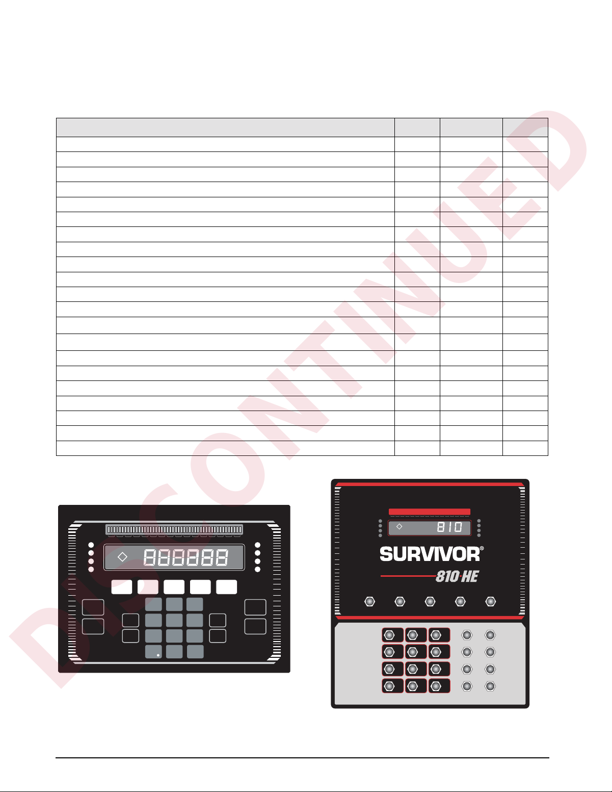
1 2 3 4 5 6 7 8 9 10 11 12 13 14 15 16
Lb
Kg
ROC
Accum
ZERO PRINTUNITSTAREG/N
DISP
TARE
TIME/
DATE
ACCUM
DISP
ROC
123
DISP
456
789
0
ENTER
SCALE
NEW
I.D.
Figure 1-1. IQ plus 800/810 Front Panel
Lb
Kg
ROC
Scale 1
Scale 2
Scale 3
Scale 4
SET
POINT
CLEAR
#
ACCUM
ZERO GROSS/NET TARE UNITS PRINT
123
456
789
•
10 11 12 13 14 15 163 4 5 6 7 8 91 2
ENTER
0
SCALE 1
SCALE 2
SCALE 3
SCALE 4
NEW I.D.DISP ACCUM
SCALE #DISP R.O.C.
SET POINTDISP TARE
CLEARTIME/DATE
Figure 1-2. IQ plus 810 HE Front Panel
IQ plus 800/810 Installation Manual
Page 9

DISCONTINUED
1.2 Front Panel Keys and Annunciators
The following section describes the front panel keys, annunciators, and display functions of the IQ plus 800/810
indicators.
Numeric keypad
123
456
789
0
ZERO
ENTER
The numeric keypad is used to enter numeric values, such as tare weights and ID
numbers. Normally, you key a number, and then press
key. Each digit appears on the display screen as entered. If you key a number and
don’t press
reverts to the previous mode and the number is ignored.
If you make a mistake entering a number, press
Continue pressing
If you key a number and press
and the display returns to normal mode.
ZERO
Resets the scale gross weight to zero. The
scale is in motion or when the displayed weight value is outside of the
configured zero range.
ENTER
and/or a function key within several seconds, the display
CLEAR
to erase the remaining digits as necessary.
G/N
before pressing
ZERO
ENTER
CLEAR
ENTER
key cannot be used when the
and/or a function
to erase a single digit.
, the number is erased
G/N
TARE
UNITS
PRINT
G/N
Toggles between Gross and Net display modes. In Net mode, the display shows
NET
net weight and the
gross weight and the
Also, you can use
TARE
Captures the current gross weight as a tare value and switches to net mode. The
gross weight must be positive and the scale at standstill to perform a tare
operation.
Tare values can also be entered using the numeric keypad, then pressing
or by sending commands to the EDP port
The
T
and rhombus appear on the display when a tare is in the system. The
and rhombus indicates a manually entered (keyed) tare.
UNITS
Toggles the display between the primary and secondary units. Although the
standard label shows pounds and kilograms, other units can be defined in the
configuration menus. See the description of the LED annunciators on page 5 for
more information.
PRINT
In normal mode and with the scale at standstill, pressing the
data to the serial port. See Section 7.0 on page 54 for information about creating
custom print formats.
annunciator lights. In Gross mode, the display shows
G
annunciator lights.
G/N
to revert to normal weighing mode if in another mode.
PRINT
TARE
pT
key sends
,
Introduction
3
Page 10

DISP
DISCONTINUED
TARE
TIME/
DA TE
DISP
ACCUM
4
DISP TARE
In the normal weighing mode,
CLEAR
T
annunciator.
CLEAR
ENTER
, the display prompts
any, and lights the
In the truck in/out mode, key in a truck ID number and press
NO ID
appears on the display. If the ID is found, press
value. If you press
truck ID.
In the Truck In/Out mode, press
TIME/DATE
Press once to display the date, press again to display the time.
You can enter new values for the date and time while they appear in the display by typing the
new value and pressing
DISP ACCUM
Displays the current weight from the accumulator register and sequentially lights the
accumulator annunciators. Press repeatedly to scroll through all five accumulators or enter an
accumulator number (0–4) and press
If you press
register.
DISP TARE
, the display prompts
DISP TARE
. Use the 24-hour format to enter time values.
displays the current weight in the tare register, if
DISP TARE
ENTER
CLR ID?
repeatedly to scroll through the stored IDs.
DISP ACCUM
CLR AC?.
.
Press
; press
CLEAR
to display the stored weight
CLEAR
again to clear the accumulate
. If the ID is not found,
again to clear the stored
DISP
ROC
NEW
I.D.
SCALE
#
DISP ROC
Displays the rate of change for weight data on the current scale channel. The ROC value is
expressed as the change in weight during a specific period of time, such as lb/min or Kg/hour.
The
DISP ROC
annunciator lights when the rate of change feature is active.
NEW ID
In the truck in/out mode,
the numeric keys and press
to enter the new ID number, save the tare, and print a weigh-in ticket, all in one step. Also, you
can use
See Section 5.3 on page 41 for information about using the truck modes.
SCALE #
Selects an individual scale channel or total channel for display.
The scale number LED annunciator lights to show which scale weight is displayed. If sources
are totaled, more than one LED is lit. The
channel is enabled and selected.
NEW ID to enter an ID number not associated with the truck program or weight storage.
key functions only if the rate of change feature is installed; the ROC
NEW ID
lets you enter a new truck ID number. Key in a number with
NEW ID to save. When a truck is on the scale, you can use NEW ID
SCALE # key functions only if more than one input
IQ plus 800/810 Installation Manual
Page 11

SET
DISCONTINUED
POINT
CLEAR
SETPOINT
Press to show defined setpoint values. When you first press this key, the display shows
two seconds, then switches to show the setpoint value. Each time you press
next defined setpoint is shown.
You can change the setpoint value by keying in a number and pressing
setpoint, press
NOTE: In Version 3.1, you can reactivate setpoints that have been turned off at the front panel.
Press the
setpoint back on.
If you make an error when keying in a value, press
to normal mode, press
You can use the
normal mode. See Section 8.3 on page 62 for more information using the
access preact values.
See Section 8.4 on page 62 for more information about naming setpoints.
CLEAR
Erases digits entered from the keyboard or clears special function values.
• In the
• In the
to display the prompt CLR ACn (where n is the accumulator number, 0–4). Press CLEAR a
second time to clear the accumulator.
• In the
the prompt CLR TR?. Press CLEAR a second time to clear the tare register.
• In the
values.
CLEAR. The message OFF appears on the display for disabled setpoints.
SETPOINT key to show the OFF status for the setpoint, then press ENTER to turn the
CLEAR to erase individual digits. To return
G/N or wait for the display to switch back.
SETPOINT key to view or change preact v alues from the front panel during the
SETPOINT function, CLEAR disables setpoints or erases individual digits.
DISP ACCUM function, with the current accumulator value displayed, press CLEAR
DISP TARE function with the current tare value displayed, press CLEAR to display
DISP TARE function (truck in/out mode), CLEAR erases truck IDs, as well as tare
SETPOINT, the
ENTER. To turn off a
SETPOINT key to
SP 1 for
Lb
Kg
ROC
Accum
Scale 1
Scale 2
Scale 3
Scale 4
LED Annunciators
The LED annunciators provide status information about the indicator.
The LEDs on the left side of the display indicate the display units and whether the value
displayed is a rate of change or accumulator value. The Lb and Kg (Units) LEDs function as
follows:
• If the displayed weight is in pounds, the Lb LED is lit; if kilograms, the Kg LED is lit.
• If the primary unit of weight is pounds, the Kg LED is lit for secondary units—or, if the
primary unit is kilograms, the Lb LED is lit for secondary units, unless the secondary unit
of weight is the same as the primary unit.
• If neither primary nor secondary units are pounds or kilograms, the Lb LED is used as a
primary units annunciator and the Kg LED is used as the secondary units annunciator.
See the descriptions of the
The scale channel LEDs on the right side of the display indicate which scale weight is
displayed. See the description of the
UNITS, DISP ROC, and DISP ACCUM keys for more information.
SCALE # key for more information.
Introduction 5
Page 12
2.0 Installation
DISCONTINUED
2.1 Power Connections
The IQ plus 800/810 can operate from either a 115
VAC or 230 VAC 3-wire power supply line at 50 or 60
Hz. It is further recommended that the 800/810 be
connected to an AC power supply that is on a separate
branch or feeder from other AC equipment that causes
step-load changes and/or other AC line disturbances.
The transformer on the power supply/display board is
pre-wired at the factory for 115 VAC operation. If the
installation requires 230 VAC operation, move the
transformer connector from J5 to J9 on the power
supply/display board. Also, be sure to install the
correct fuse. See Section 10.7 on page 91 for
specifications
SERIAL COMM WIRING
J7-1
J7-2
PINS 1–6:
J7-3
PRINTER PORT
J7-4
CONNECTORS
J7-5
J7-6
J7-7
PINS 7–12:
J7-8
EDP PORT
J7-9
CONNECTORS
J7-10
J7-11
J7-12
MAIN
BOARD
DISPLAY
BOARD
TO J10
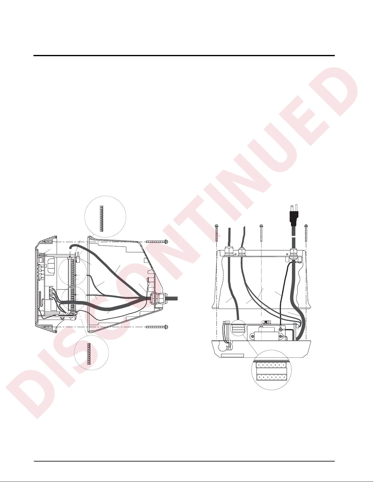
2.2 Board Connections
The main CPU board is connected to the power
supply/display board by two ribbon cables. The power
ribbon cable connects between J1 on both boards; the
data ribbon cable connects between J2 on both boards.
Figures 2-1 through 2-3 show board locations and
cabling for the IQ plus 810, HE, and SS models.
Board locations and cabling for the IQ plus 800 are
essentially the same as for the IQ plus 810.
SETUP
SWITCH
TO J7
J7
TO J4
J4
DIGITAL I/O
DIGITAL I/O WIRING
J4-1 DIG OUT 1
J4-2 DIG OUT 2
J4-3 DIG OUT 3
J4-4 DIG OUT 4
J4-5 DIG IN 3
J4-6 DIG IN 2
J4-7 DIG IN 1
J4-8 GND
J4-9 GND
J4-10 +5 VDC
SERIAL
COMMUNICATIONS
LOAD CELL
GROUND
AC POWER
Figure 2-1. IQ plus 810 Wiring, Side View
SERIAL COMMUNICATIONS
CABLE TO J7
GROUND
LOAD CELL
CABLE TO J10
J10
J10-1 +Sig
J10-2 –Sig
J10-3 +Sense
J10-4 –Sense
J10-5 Shield
J10-6 +Exc
J10-7 –Exc
DIGITAL I/O
CABLE TO J4
SETUP SWITCH
7 6 5 4 3 2 1
Load Cell Wiring
J10
AC POWER
J7
Figure 2-2. IQ plus 810 Wiring, Top View
6 IQ plus 800/810 Installation Manual
Page 13
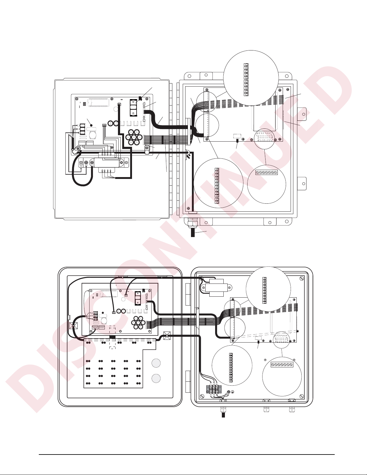
Power Supply Display Board
DISCONTINUED
Display Driver
Fuse
DIGITAL I/O WIRING
J4-10
+5 VDC
J4-9
GND
J4-8
GND
J4-7
DIG IN 1
J4-6
DIG IN 2
J4-5
DIG IN 3
J4-4
Battery
REMOVE JUMPER
J6
J11 BEFORE
INSTALLING
BATTERY
J2
Data
Cable
Power
Ribbon
Cable
CPU Board A/D Module
J4-3
J4-2
J4-1
DIG OUT 4
DIG OUT 3
DIG OUT 2
DIG OUT 1
J1
J2
AC Power
Cable
Transformer
Power Supply Display Board
Display
Driver
Fuse
J4
Keyboard
AC Power Cable
Power Ribbon Cable
Figure 2-3. IQ plus 810 SS Wiring
REMOVE JUMPER
J6
J11 BEFORE
INSTALLING
BATTERY
Battery
J2
J1
J1
Data
Ribbon
Cable
Power Ribbon
Cable
AC Power
Cable
Pre-drilled holes for
Batching Switch Option
Data
Ribbon
Cable
Power
Ribbon
Cable
SERIAL COMM.
J7-12
J7-11
7-12
J7-10
EDP
J7-9
PORT
J7-8
J7-7
J7-6
1-6
J7-5
PRINTER
J7-4
PORT
J7-3
J7-2
J7-1
AC Power In
Transformer
SERIAL COMM.
J7-12
J7-11
J7-10
J7-9
J7-8
J7-7
J7-6
J7-5
J7-4
J7-3
J7-2
J7-1
Setup Switch
J4
J7
7-12
EDP
PORT
1-6
PRINTER
PORT
1234567
LOAD CELL WIRING
+Sig
1
–Sig
2
+Sense
3
–Sense
4
Shield
5
+Exc
6
–Exc
7
DIGITAL I/O WIRING
J4-10
J4-9
J4-8
J4-7
J4-6
J4-5
J4-4
J4-3
J4-2
J4-1
CPU Board
Setup Switch
+5 VDC
GND
GND
DIG IN 1
DIG IN 2
DIG IN 3
DIG OUT 4
DIG OUT 3
DIG OUT 2
DIG OUT 1
A/D Module
1234567
LOAD CELL WIRING
+Sig
1
–Sig
2
+Sense
3
–Sense
4
Shield
5
+Exc
6
–Exc
7
J1
J2
AC Power In
Figure 2-4. IQ plus 810 HE Wiring
Installation 7
Page 14
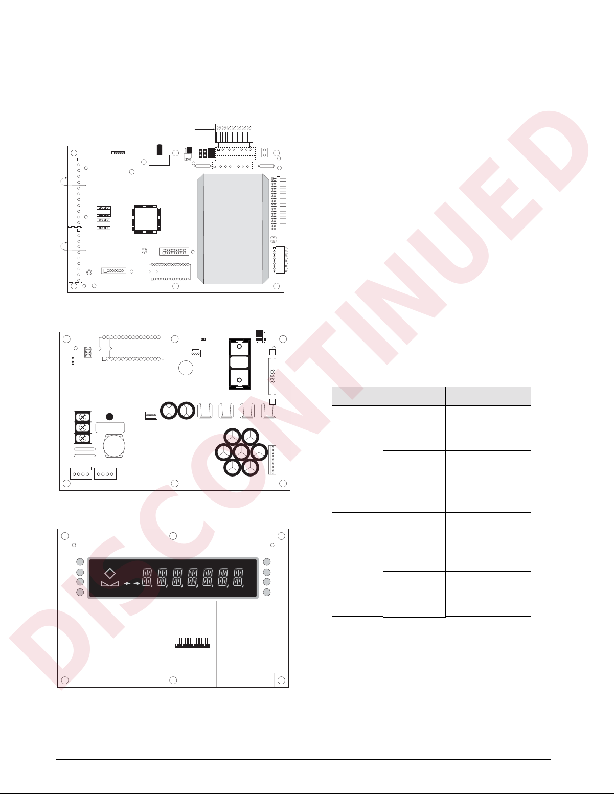
2.3 Board Diagrams
DISCONTINUED
Figures 2-5 through 2-7 show major component
locations on the IQ plus 800/810 circuit boards.
JP1
JP3
J6
1234567
JP2
(1st Load Cell Term)
(2nd Load Cell Term)
A/D Converter
B1
REMOVE JUMPER
J11 BEFORE
INSTALLING
BATTERY
J2
J1
J11
J2
Load Cell Connector
J10
(Terminal Screws on Back)
J9
(Factory Use Only)
(J7) Serial Communications
U22
U24
(J4) Digital I/O Wiring
J5
SW1
J8
J6
EPROM
Figure 2-5. CPU Board, Component Side
J3
J8
EEPROM
2.4 Load Cell Wiring
Wire the analog input cable from the load cell or
junction box to the removable connector and plug into
the CPU board at J10 near the A/D module. If your
indicator was purchased after June 1, 1996, the A/D
module is surface mounted to the CPU board.
Note that earlier indicators (with A/D modules
mounted on standoffs) have J10 pin assignments in
reversed order from those shown in Table 2-1.
For a single-channel A/D module, use the upper
plug-in connector for the load cell. If a dual-channel
A/D module is being used, plug the second load cell
cable into the lower connector at J10.
If using 4-wire load cell cable, leave jumpers JP1 and
JP2 on (these jumpers connect pins 3 and 6, 4 and 7, at
terminal J10). For a 6-wire installation using sense
leads, remove the jumpers.
For dual-channel A/D modules, there are jumper pins
on the board near J10. The sense jumpers are labeled
JP1–JP2 for channel one, and JP3–JP4 for channel
two. Leave the jumpers installed for a 4-wire cable,
remove them for a 6-wire installation.
Table 2-1 shows the J10 pin assignments for load cell
connections.
L
(AC HOT)
N
(AC NEUTRAL)
G
(AC GROUND)
F1 (FUSE)
C32
C34
J9J5
J7
C33
T2
U8U7U6U5
J1
Figure 2-6. Power Supply/Display Board, Component Side
DS6
DS7
DS8
DS9
NET
P
T
BG–
0
J4
DS5
DS4
DS3
DS2
Channel J10 Pin Signal
11+SIGNAL
2 –SIGNAL
3 +SENSE
4 –SENSE
5 SHIELD
6 +EXCITATION
7 –EXCITATION
21+SIGNAL
2 –SIGNAL
3 +SENSE
4 –SENSE
5 SHIELD
6 +EXCITATION
7 –EXCITATION
Table 2-1. J10 Pin Assignments (Load Cells)
Figure 2-7. Power Supply/Display Board, Display Side
8 IQ plus 800/810 Installation Manual
Page 15

2.5 Serial Communications Wiring
DISCONTINUED
Terminal block J7 on the CPU board connects both the
EDP (Electronic Data Processing) port and the printer
port. See Section 3.2.5 on page 30 for information
about configuring the serial ports.
The EDP port supports full-duplex RS-232 or simplex
20 mA current loop communication, with half-duplex
RS-485 and full-duplex 20 mA current loop as
optional features. The printer port can support full
duplex RS-232 and simplex 20 mA transmissions.
(Pin 3 is used as an RS-232 receive in some custom
software versions only.) See Section 9.8 on page 71
for information about serial communications options.
Table 2-2 shows the J7 pin assignments for serial
communications connections.
20mA
Port J7 Pin RS-232
Printer 1
2
3
4 –20mA OUT
5 TxD
6 GND +20mA OUT
EDP 7 +20mA IN 485-A
8
9 RxD
10 –20mA OUT
11 TxD
12 GND +20mA OUT
Table 2-2. J7 Pin Assignments (Serial Communications)
RS-485 Wiring
Biasing resistors R38 and R39 can be used to assure
that the RS-485 loop remains in a
idle. If the indicator is installed at the end of the
RS-485 cable, install a 100Ω termination resistor
across the inputs.
The IQ plus 800/810 RS-485 option requires
installation of a single chip (U24) to provide 2-wire,
half-duplex communications. RS-485
SPACE states are generated or detected when the
following conditions exist:
•
MARK state if 485-A (pin J7-7) is > 200 mV
lower than 485-B (J7-8)
•
SPACE state if 485-A (pin J7-7) is > 200 mV
higher than 485-B (J7-8)
Equipment using the 4-wire RS-485 implementation
can be incorporated into a network of IQ plus 800/810
indicators by tying the transmit (A) and receive (A)
RxD
Current Loop
–20mA IN 485-B
MARK state when
RS-485
R38/GND
R39/+5V
MARK and
pins together, and tying the transmit (B) and receive
(B) pins together.
2.6 Digital I/O Wiring
The standard unit allows three digital inputs and four
digital outputs. Wire any active digital inputs and
outputs to connector J4 on the CPU board. Table 2-3
shows the digital I/O assignments for the J4
connector.
J4 Pin Signal
1 DIG OUT 1
2 DIG OUT 2
3 DIG OUT 3
4 DIG OUT 4
5 DIG IN 3
6 DIG IN 2
7 DIG IN 1
8 GND
9 GND
10 +5 VDC
Table 2-3. J4 Pin Assignments (Digital I/O)
Typically, digital outputs control relays which operate
other equipment. Each output is a normally-open
collector circuit, capable of sinking 250 mA when on
and withstanding +40 VDC when off. All logic levels
are active (on) when a low voltage signal (0 VDC) is
present. The output circuits also include 5V pull-up
resistors to send a 5V TTL or 5V CMOS logic signal
when the outputs are closed (on). Use the SETPNTS
menu to configure the digital outputs.
You can wire as many as three external switches to the
digital inputs. These inputs can be set to duplicate
keyboard functions. When used with the batching
switch, PN 19369, the inputs can be set up to start,
run, pause, and stop batch sequences. As with the
outputs, the inputs are active (on) with low voltage (0
VDC) and can be driven by TTL or 5V logic without
additional hardware. Use the DIG IN menu to
configure the digital inputs (see Section 3.2.7 on
page 34).
NOTE: Indicators manufactured prior to September 1,
1996 do not provide a 5 VDC power supply at J4, pin
10. Two methods may be used to provide 5 VDC
power to this pin:
• Solder an insulated jumper wire from J1, pin
4 to J4, pin 10.
• Use an external power supply to energize J4,
pin 10. PN 16418 is recommended.
Indicators made after September 1, 1996 have 5 VDC
built into J4, pin 10.
Installation 9
Page 16
2.7 Wall- and Panel-Mounting
DISCONTINUED
The following sections describe wall- and
panel-mounting procedures for the IQ plus 800/810
indicators.
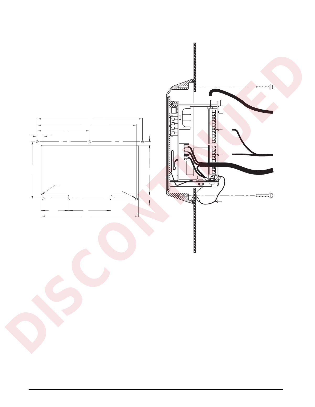
2.7.1 IQ plus 810 Panel Mount Kit
The panel mounting kit for the IQ plus 810 desktop
model contains five screws with washers to replace the
original screws holding the body to the faceplate.
1. Create a template using the drawing in
Figure 2-8 to mark the hole cutout in the
panel.
10
9-7/16
5
9/16
15/32
To J10
To J7
Load Cell
Cable
7-29/64
1/8 R (8) OPTIONAL
7/32 DIA THRU (5)
2-5/8
Figure 2-8. IQ plus 810 Panel Cutout
4
9-1/4
2. Disconnect power to the indicator.
3. Remove the back of the indicator by
unscrewing the six machine bolts holding the
back to the faceplate.
4. Temporarily remove any cable connections
from the indicator terminals. Remove the
ground cable from the cast lug on the rear of
the indicator case.
5. Using a template made from the drawing
shown in Figure 2-8, transfer the cutout to the
panel. Cut out the panel and drill the holes to
size. Hold the faceplate against the panel and
secure with the five machine screws and
washers provided.
6. Attach the ground wire that was connected to
the lug on the indicator body to one of the five
screws (see Figure 2-9).
7. Reattach cables to indicator terminals. Power
up and test the indicator.
6-1/2
5/8
To J4
Ground
Figure 2-9. IQ plus 810 Panel Mount Wiring
Communications
Cable
AC Power Cable
10 IQ plus 800/810 Installation Manual
Page 17

2.7.2 IQ plus 810 Wall Mount Kit
Remove installation screw after
threaded wall anchor is spread
Threaded eyebolts
hold indicator case
to wall anchor
DISCONTINUED
A wall mount kit is available for mounting the IQ plus
810 against vertical surfaces. The indicator mounting
plate both swivels and tilts for adjusting the viewing
angle. The indicator case is secured to the mounting
plate with two machine screws turned into threaded
holes in the bottom of the indicator body. Overall
dimensions are shown in Figures 2-10 and 2-11.
6.28
6.32
4.0
6.34
9.48
2.7.3 IQ plus 810 SS and HE Model Wall Mounting
If you are permanently mounting an SS or HE model
to a wall, Underwriters Laboratories (UL) requires
that you run the AC power cord in conduit and connect
it to the case with a conduit hub according to standard
construction practices. For portable units, the standard
power cord is sufficient.
Figure 2-12 shows a typical method for mounting the
indicator which maintains its portability. Use the
installation screws to secure four #10 wall anchors.
Then remove the installation screws and attach the
indicator with four threaded eye bolts.
Figure 2-10. IQ plus 810 Wall Mount (Side View)
6.78
Figure 2-12. Wall Mounting for HE and SS Models
4.0
Figure 2-11. IQ plus 810 Wall Mount (Front View)
Installation 11
Page 18
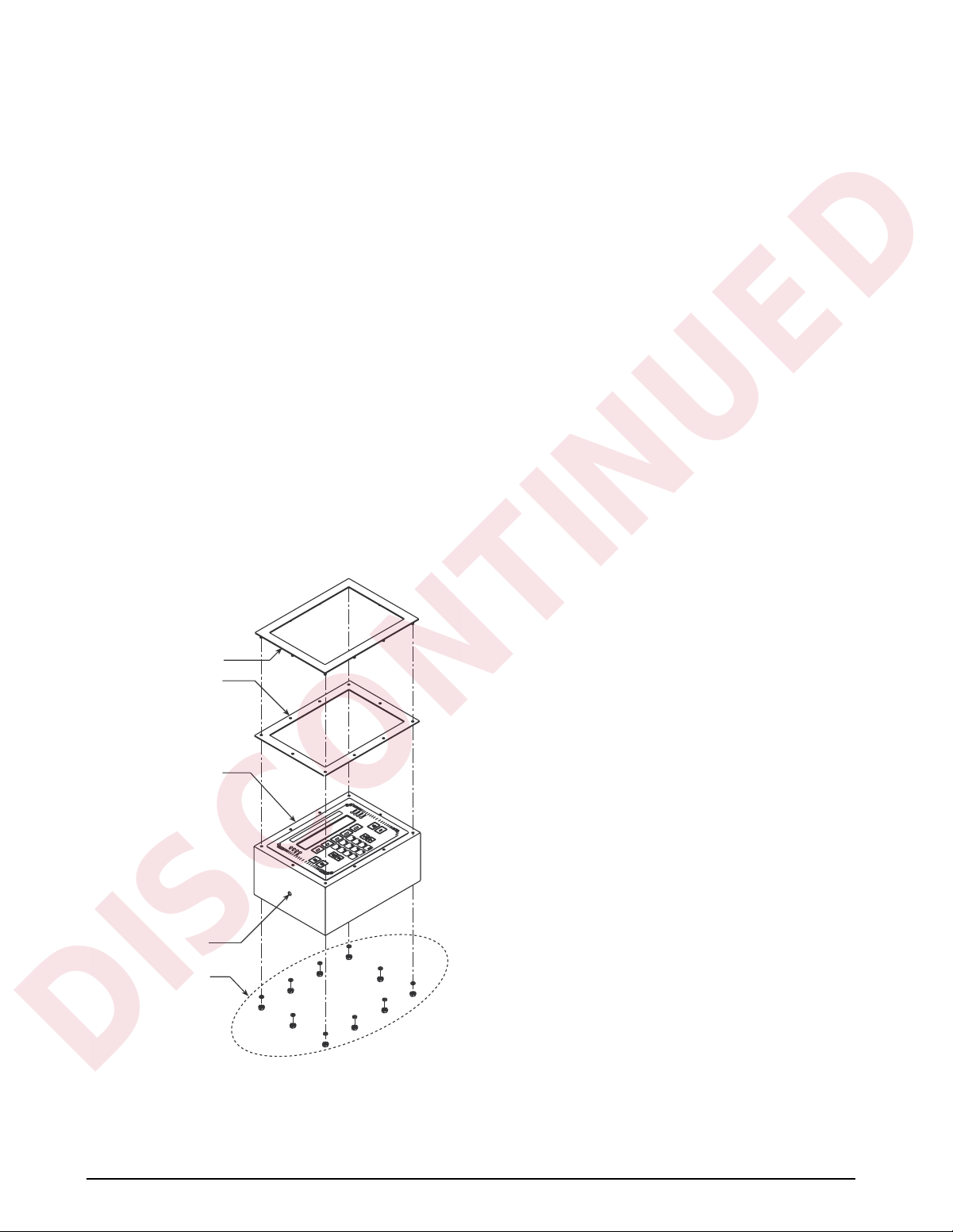
2.7.4 IQ plus 800 Panel Mount Kit
DISCONTINUED
Use the following procedure when panel mounting IQ
plus 800 indicators manufactured after September
1997. These indicators use the same cutout
dimensions as that for the older IQ plus 800 models;
the panel mount kit includes a larger bezel and gasket
for secure mounting.
1. Make a 9 13/16 W x 7 5/16 H inch cutout in
the panel.
2. Remove the tilt stand from the indicator
enclosure.
3. Remove the 14 screws and washers that hold
the backplate to the enclosure body. Note the
location of the larger fillister head screw
above the setup switch access screw.
4. Slowly pull the backplate away from the
enclosure. Disconnect the ribbon cable
extension from the front panel membrane
overlay tail before attempting to completely
remove the backplate and boards from the
enclosure.
5. Remove the 10 nuts and washers that secure
the bezel to the front of the enclosure (see
Figure 2-13).
Bezel
Gasket
6. Remove the standard bezel and gasket from
the front of the indicator and replace with the
larger bezel and gasket from the panel mount
kit. Replace the washers and nuts to secure
the new front bezel.
7. Feed the power, load cell, and
communications cables through the cord grips
on the backplate. Make cable connections as
required.
8. Reassemble the indicator enclosure to the
backplate and boards. Move the indicator
halves together until the ribbon cable
extension can be reconnected to the front
panel membrane overlay tail. Reconnect the
ribbon cable extension then slide the
backplate and boards fully into the enclosure.
9. Place the indicator face-down on the antistatic
mat. Align the holes in the backplate with
those in the enclosure, then reassemble the
washers and screws remov ed in step 3. Use an
alternating pattern when tightening the screws
to prevent distorting the backplate gasket.
10. Feed indicator cables through the panel cutout
from front to rear. Insert the indicator into the
panel from the front and hold in place.
11. From the rear of the panel, use the 1/4-20 x
3/8 pan-head screws and lock washers
provided to attach the panel mount brackets to
the sides of the indicator as shown in Figure
1.
12. Thread the four 10-32 x 1 3/4-inch
round-head machine screws into the panel
mount brackets and tighten until the indicator
is held securely against the panel.
Enclosure
Scale 1
Scale 2
Scale 3
Scale 4
SET
POINT
PRINT
CLEAR
UNITS
NEW
I.D.
3
TARE
SCALE
#
6
2
9
G/N
5
Lb
1
8
ENTER
Kg
ROC
Accum
4
ZERO
0
7
DISP
.
ACCUM
DISP
ROC
DISP
TARE
TIME/
DATE
2.8 Battery Replacement
The 3.0V lithium battery on the power supply/display
board maintains the real-time clock and protects data
stored in the system RAM when the indicator is not
connected to AC power.
System RAM data includes time and date, print
formats, truck ID storage, and setpoint configuration.
This information is lost if the battery loses power and
the indicator is disconnected from AC power. To
Mounting hole for
panel mount bracket
Retaining nuts & washers
for front bezel (10 each)
prevent loss of data, do the following:
• Periodically check the battery voltage and
replace when the voltage drops. The battery
should last a minimum of one year.
• Use the Revolution
™
configuration utility or
EDP commands (see Section 6.2 on page 52)
to store a copy of the indicator configuration
on a PC before attempting battery
replacement. If any data is lost, the indicator
Figure 2-13. IQ plus 800 Bezel and Gasket Replacement
(for indicators manufactured after September 1997)
12 IQ plus 800/810 Installation Manual
configuration can be restored from the PC.
Page 19

3.0 Configuration
DISCONTINUED
To configure the IQ plus 800/810 indicators, the
indicator must be placed in setup mode. The setup
switch is located on the top edge of the
vertically-mounted CPU board, near the middle of the
board. Moving the two-position setup switch toggles
between setup or normal mode. Access to the setup
switch depends on the type of indicator.
NOTE: Entering setup mode erases any pushbutton zero
values.
IQ plus 800
The setup switch is accessed by removing a screw on
the enclosure backplate. Switch position is changed
by inserting the screwdriver into the access hole and
moving the switch left (CONFIGURE) or right
(RUN), as indicated by the label immediately below
the access hole. Figure 3-1 shows a cutaway view of
the setup switch access screw and the setup
switch.
ACCESS SCREW
GUARD PLATE
SETUP SWITCH
Figure 3-1. IQ plus 800 Setup Switch Access
NOTE: For IQ plus 800 enclosures manufactured prior to
September 1997, the setup switch is accessed by
removing four screws that secure the setup switch cover
to the top of the enclosure.
IQ plus 810
The setup switch (SW1) is accessed by separating the
enclosure halves. See Figure 2-5 on page 8 for switch
location.
When the indicator is placed in setup mode, the word
CONFIG is shown on the display. The CONFIG menu
is the first of the main menus used to configure the
indicator. Detailed descriptions of these menus are
given in Section 3.2. When configuration is complete,
move the setup switch to the run position and replace
the setup switch access screw or reassemble the
enclosure, as required.
3.1 Configuration Methods
The IQ plus 800/810 indicators can be configured by
using the front panel keys to navigate through a series
of configuration menus or by sending commands or
configuration data to the EDP port. Configuration
using the menus is described in Section 3.1.3.
Configuration using the EDP port can be
accomplished using either the EDP command set
described in Section 6.0 or the Revolution
configuration utility.
3.1.1 Revolution Configuration
The Revolution configuration utility provides the
preferred method for configuring the IQ plus 800/810
indicators. Revolution runs on a personal computer to
set configuration parameters for the indicator. When
Revolution configuration is complete, configuration
data is downloaded to the indicator.
Revolution supports both uploading and downloading
of indicator configuration data. This capability allows
configuration data to be retrieved from one indicator,
edited, then downloaded to another.
To use Revolution, do the following:
1. Install Revolution on an IBM-compatible
personal computer running Windows
Windows 95. Minimum system requirements
are 4MB of extended memory and at least
5MB of available hard disk space.
2. With both indicator and PC powered off,
connect the PC serial port to the RS-232 pins
on the indicator EDP port.
3. Power up the PC and the indicator. Use the
setup switch to place the indicator in setup
mode.
4. Start the Revolution program.
Figure 3-2 on page 14 shows an example of one of the
Revolution configuration displays.
®
3.11 or
™
Windows® is a registered trademark of Microsoft Corporation
Configuration 13
Page 20

DISCONTINUED
Figure 3-2. Sample Revolution Configuration Display
3.1.3 Front Panel Configuration
The IQ plus 800/810 indicators can be configured using a series of menus accessed through the indicator front
panel when the indicator is in setup mode. Table 3-1 provides a summary of the configuration functions provided
by each of these menus.
Revolution provides online help for each of its
configuration displays. Parameter descriptions
provided in this manual for front panel configuration
can also be used when configuring the indicator using
Revolution: the interface is different, but the
parameters set are the same.
3.1.2 EDP Command Configuration
The EDP command set can be used to configure the
IQ plus 800/810 indicators using either a personal
computer, terminal, or remote keyboard. Like
Revolution, EDP command configuration sends
commands to the indicator EDP port; unlike
Revolution, EDP commands can be sent using any
external device capable of sending ASCII characters
over a serial connection.
EDP commands duplicate the functions available
using the indicator front panel and provide some
functions not otherwise available. EDP commands can
be used to simulate pressing front panel keys, to
configure the indicator, or to dump lists of parameter
settings. See Section 6.0 for more information about
using the EDP command set.
Menu Menu Function
CONFIG Configuration Configure input channels and select general indicator functions. CONFIG menu is used to set
grads, zero tracking, zero range, motion band, overload, and digital filtering for each scale
channel, select truck modes and power-up mode, set consecutive number initial value, set
tare function, define passwords, and enable optional features.
SET ALG Set Analog Select input channels, TOTALS channel configuration, resolution, and analog filtering.
FORMAT Format Set display format (units, decimal point position, display divisions) for primary, secondary, and
rate-of-change weight displays, time and date information, and define setpoint names.
SETPNTS Setpoints Configure setpoints. See Section 8.0 for more information about setpoint configuration.
SERIAL Serial Configure EDP, printer, and auxiliary communications ports.
P FORMT Print Format Set print format used for demand, truck, and setpoint push-print tickets. See Section 7.0 for
more information about print formatting.
DIG IN Digital Input Assign digital input functions.
ALG OUT Analog Output Configure analog output modules. Used only if analog output option is installed.
BAR GRF Bar Graph Configure bar graph function. Used only if bar graph option is installed.
CALIBRT Calibrate Calibrate input channels. See Section 4.0 for calibration information.
VERSION Version Displays installed software version number.
Table 3-1. IQ plus 800/810 Menu Summary
Four front panel keys are used as directional keys to navigate through the menus in setup mode (see Figure 3-3).
The
SETPOINT and CLEAR keys scroll left and right (horizontally) on the same level; DISP TARE and TIME/
DATE move up and down (vertically) to different menu levels.
14 IQ plus 800/810 Installation Manual
Page 21
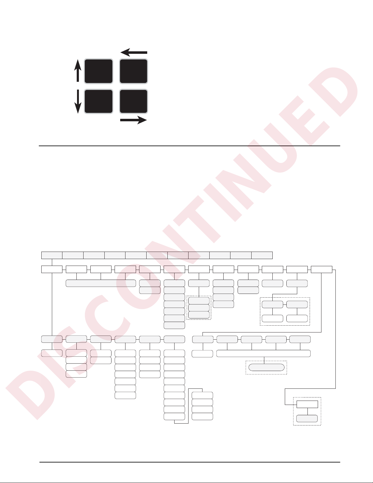
To select a parameter, press SETPOINT or CLEAR
DISCONTINUED
until the desired menu group appears on the display,
DISP
TARE
SET
POINT
then press
level. When moving down through the menus, the
default setting appears first on the display . To change a
default, scroll left or right through the various options
TIME/
DA TE
CLEAR
for that level. When the desired option appears on the
display , press
move back up one level. For parameters requiring a
numerical entry, key in the number, press
scroll up to lock in the number.
Figure 3-3. Menu Navigation Keys
3.2 Menu Structures and Parameter Descriptions
The following sections provide graphic
representations of the IQ plus 800/810 menu
structures (Figures 3-4 through 3-15). In the actual
menu structure, the settings you choose under each
parameter are arranged horizontally. To save page
space, menu choices are shown in vertical columns.
The factory default setting appears at the top of each
column. Settings shown surrounded by a dotted-line
box only appear under the special circumstances
explained under each box.
Most menu diagrams are accompanied by one or more
tables that describe all parameters and parameter
values associated with that menu option. Default
parameter values are shown in bold type.
TIME/DATE to move down to the desired
DISP TARE to lock in your selection and
ENTER, and
3.2.1 Configuration Menu
CONFIG SET ALG
SCALE 1 SCALE 2
same as SCALE 1
ZTRKBNDGRADS
number
OFF
0.5 D
1 D
3 D
1.9%
100%
XXXXXXX CALIBRT XXXXXXXVERSIONXXXXXXXBAR GRFALG OUTDIG INXXXXXXXSERIAL P FORMTSETPNTSFORMATXXXXXXX
1 D
2 D
3 D
5 D
PWRUPMD
GO
DELAY
OVRLOAD
FS + 2%
FS + 1D
FS + 9D
FS
OFF
MODE 1
MODE 2
MODE 3
MODE 4
MODE 5
MODE 6
DIGFLTR
4
8
16
32
64
128
4 RT
8 RT
16 RT
32 RT
OFF BOTH
NORMAL
BI-DIR
AUTO
if PK HOLD is
ON
ACCUM
64 RT
128 RT
SCALE 4SCALE 3
MOTBANDZRANGE
10 D
20 D
OFF
TARE FNPK HOLDTARE200
NO TARE
PB TARE
KEYED
ON
1
2
ROC
LGLMODE
LEGAL
INDUST
access code number
OFF/ON
if OFF
number
PASSWRDPEAK
SP PWDCFG PWD
passwordpassword
if ON
3.13 and later only
FEATUREPASSWRDCONSNUM
OFF
A/B
DEFAULT
RESET
Software versions
Figure 3-4. Configuration Menu
Configuration 15
Page 22

CONFIG Menu
DISCONTINUED
Parameter Choices Description
Level 2 submenus
SCALE 1–4 GRADS
ZTRKBND
ZRANGE
MOTBAND
OVRLOAD
DIGFLTR
PWRUPMD GO
DELAY
TARE200 OFF
MODE 1
MODE 2
MODE 3
MODE 4
MODE 5
MODE 6
PK HOLD OFF
NORMAL
BI-DIR
AUTO
TARE FN BOTH
NO TARE
PB TARE
KEYED
LGLMODE LEGAL
INDUST
CONSNUM 0
number
PASSWRD OFF
CFG PWD
SP PWD
Specifies the analog input channel being configured. See level 3 submenus for
configuration choices.
Power up mode. In GO mode, the scale goes into operation immediately after a brief
power up display test. In DELAY mode, the scale performs a power up display test, then
warms up (WARM UP and standstill symbol displayed). Indicator becomes operational
when no motion is detected for 30 seconds. DELAY mode is used where local regulations
require a warm-up period.
200 ID/Tare Truck In/Truck Out mode. Specifies one of six truck modes. If selected, the
indicator shifts from normal weighing mode to the selected truck mode. See Section 5.3
on page 41 for more information about truck modes.
MODE 1: Auto clear ID, keyed tares, value swapping
MODE 2: Auto clear ID, no keyed tares, value swapping
MODE 3: Stored ID, keyed tares, value swapping
MODE 4: Stored ID, no keyed tares, value swapping
MODE 5: Stored ID, keyed tares, no value swapping
MODE 6: Stored ID, no keyed tares, no value swapping
Peak hold function. Optional feature used to hold display of the highest net weight
achieved during a weighing cycle.
If the peak hold function is enabled, PK HOLD is set on for all channels. The TOTAL
channel peak value is independent of the individual channels; it does not represent the
sum of the channel peak values. See Section 10 for more information about the peak hold
function.
Tare function. Enables or disables push-button and keyed tares. Possible values are:
BOTH: Both push-button and keyed tares are enabled
NO TARE: No tare allowed (gross mode only)
PB TARE: Push-button tares enabled
KEYED: Keyed tares enabled
Legal/industrial mode. Controls whether scale switches to gross or net display when a
tare of zero is entered in gross mode. If LEGAL is selected, scale r eturns to gross mode; if
INDUST is selected, scale switches to net display.
Consecutive numbering. Specifies starting value for sequential numbering used to count
batch sequences or serialize ticket numbers. The consecutive number can be printed on
any print ticket; value is incremented after it is printed. If consecutive number is not
printed, it is effectively disabled. The CONSECNUM EDP command allows you to view or
change consecutive numbers.
Password. Optional feature supports two passwords: one for configuration menus in
setup mode (CFG PWD), one for setpoint configuration using supervisor switch and
SETPOINT key (SP PWD). Passwords can be entered only if feature is enabled (see
FEATURE parameter).
Enter up to seven digits for each password. See Section 9.4 on page 67 for more
information.
Table 3-2. Configuration Menu Parameters
16 IQ plus 800/810 Installation Manual
Page 23

CONFIG Menu
DISCONTINUED
Parameter Choices Description
FEATURE ACCUM
ROC
PEAK
PASSWRD
A/B
DEFAULT RESET Press the down (TIME/DATE) key to reset configuration parameters to default values. This
Level 3 submenus
GRADS number Graduations. Specifies the number of full scale graduations. The value entered should be
ZTRKBND OFF
0.5 D
1 D
3 D
ZRANGE 1.9%
100%
MOTBAND 1D
2 D
3 D
5 D
10 D
20 D
OFF
OVRLOAD FS + 2%
FS + 1D
FS + 9D
FS
Allows you to verify current feature status or to activate a feature. See the Level 3
parameter descriptions on page 18 for information about activating these features.
parameter is available only with software versions 3.13 and later.
NOTE: Indicator must be reconfigured and load cells recalibrated after performing this
function.
consistent with legal requirements and environmental limits on system resolution. Enter a
value with the numeric keypad; exit upward to save the new value.
To calculate GRADS, use the formula, GRADS = Capacity / Display Divisions.
Display divisions for primary and secondary units are specified on the FORMAT menu.
Zero track band. Automatically zeroes the scale when within the range specified, as long
as the input is within the ZRANGE and scale is at standstill. Selections are ± display
divisions. Maximum legal value varies depending on local regulations.
Zero range. Selects the range within which the scale can be zeroed. The 1.9% selection is
± 1.9% around the calibrated zero point, for a total range of 3.8%. Indicator must be in
standstill and in gross weight display mode to zero the scale. Use 1.9% for legal-for-trade
applications
When the ZERO key is pressed while displaying the total channel, the amount on each
individual channel is zeroed off, if possible. If the ZERO is not possible on all channels,
then the ZERO is denied.
Motion band. Sets the level, in display divisions, at which scale motion is detected by
comparing the current display with the previous display. If motion is not detected for 1
second or more, the standstill symbol lights, enabling the scale to process a PRINT
command. Maximum legal value varies depending on local regulations.
If OFF is selected, ZTRKBAND must also be set to OFF. TOTAL channel is considered at
standstill when all individual channels are out of motion.
Overload. Determines the point at which the display blanks and an out-of-range error
message is displayed. Maximum legal value varies depending on local regulations.
When any individual channel is overloaded, the total channel display is also blanked.
Table 3-2. Configuration Menu Parameters (Continued)
Configuration 17
Page 24

CONFIG Menu
DISCONTINUED
Parameter Choices Description
DIGFLT 4
ACCUM
ROC
PEAK
PASSWRD
A/B
8
16
32
64
128
4 RT
8 RT
16 RT
32 RT
64 RT
128 RT
1
2
OFF
ON
Digital filtering. Selects the digital filtering rate used to reduce the effects of mechanical
vibration from the immediate area of the indicator.
Choices indicate the number of A/D conversions per update that are averaged to obtain
the displayed reading. A higher number gives a more accurate display by minimizing the
effect of a few noisy readings, but slows down the settling rate of the indicator.
RATTLETRAP
filtering repeating vibrations caused by mechanical noise from nearby machines but may
increase settling times over standard digital filter selections.
See Section 10.5 on page 89 for more information on digital filtering.
ACCUM is a standard feature and can simply be turned ON or OFF. Use the following
procedure to activate the ROC, PEAK, PASSWRD, and A/B features:
1. From the selected feature (ROC, PEAK, PASSWRD, or A/B), press TIME/DATE to
move down and show the feature status. If OFF, press TIME/DATE again to display a
unique number generated by the indicator. This number is used to calculate the
access code for the feature.
2. Record the generated number, then use the number in the following equation to
calculate the feature access code:
(generated_number
where feature_type is:
For example, if the number generated for the ROC feature is 5000, the access code
would be:
(5000 x 5) + 14 = 25000 + 14 = 25014
3. Use the numeric keypad to enter the calculated access code, then press ENTER. The
display should return to show the changed feature status value (ON).
®
selections (shown with “RT” after the number) are most effective at
x 5) + feature_type
14 for ROC
21 for PEAK
28 for PASSWRD
35 for A/B
The CLEARALLFEATURES EDP command can be used to turn off all active features.
See Section 9.0 for more information about using these features.
Table 3-2. Configuration Menu Parameters (Continued)
18 IQ plus 800/810 Installation Manual
Page 25

3.2.2 Set Analog Menu
DISCONTINUED
CONFIG SET ALG
1 2
1 3
1 3 4
1 2 3 4
1 FAST
OFF
ENABLE
T ONLY
OFF
Available if multiple
channels are selected
OFF
P1>CH3
P>CH3+4
STANDRD
HIGH
60 HZ
50 HZ
Figure 3-5. Set Analog Menu
SET ALG Menu
Parameter Choices Description
Level 2 submenus
CHANS 1
1 2
1 3
1 3 4
1 2 3 4
1 FAST
TOTALS OFF
ENABLE
T ONLY
PULS IN OFF
P1>CH3
P>CH3+4
RESOLUT STANDRD
HIGH
FREQ 60 HZ
50 HZ
ALGFLTR 8 HZ
OFF
2 HZ
Channels. Selects the channels used for analog input to the indicator. The standard unit has
one channel; up to four channels can be specified. If the Jetpak option is installed, channel
1 can be selected as a high-speed channel (1 FAST) with an update rate of 100/second.
TOTALS channel configuration. Possible values are:
OFF: TOTALS channel disabled. This is the default value for all channel configurations.
ENABLE: TOTALS channel enabled. Indicator displays TOTALS with other configured
channels.
T ONLY: Indicator displays only the TOTALS channel
Pulse input. This option is not available at this time.
Resolution. Selects between standard (360 000 grads a t 120V, 60 Hz, 20 updates/sec) and
high resolution (740 000 grads at 120V, 60 Hz, 10 updates/sec). Internal resolution is
increased by 20% with 50 Hz AC power supply.
Frequency. Sets the A/D converter to match AC power supply.
Analog filter. Selects the range used for filtering mechanical and electrical noise. 8 Hz value
has a medium filtering effect; 2 Hz has the greatest effect. Normally, the minimum filter value
that allows a stable display should be selected. If digital filtering is also used, select either 2
Hz or 8 Hz for this parameter. See Section 10.5 on page 89 for more information about
analog filtering.
XXXXXXX CALIBRT XXXXXXXVERSIONXXXXXXXBAR GRFALG OUTDIG INXXXXXXXSERIAL P FORMTSETPNTSFORMATXXXXXXX
ALGFLTRFREQRESOLUTPULS INCHANS TOTALS
8 HZ1
OFF
2 HZ
Table 3-3. Set Analog Menu Parameters
Configuration 19
Page 26

3.2.3 Format Menu
DISCONTINUED
CONFIG SET ALG
PRIMARY SECNDRY RATECHG
DSP DIV UNITSDEC PNT
1
2
5
DSP DIV MULTUNITSDEC PNT
5
1
2
8888888
888888.8
88888.88
8888.888
888.8888
88.88888
8.888888
8888800
8888880
888888.8
88888.88
8888.888
888.8888
8.888888
8888800
8888880
8888888
LB
KG
OZ
TN
GR
G
NONE
KG
OZ
TN
GR
G88.88888
NONE
LB
same as SCALE 1
DSP DIV TIMEMULTDEC PNT
1
2
5
number
8888888
888888.8
88888.88
8888.888
888.8888
88.88888
8.888888
8888800
8888880
SCALE 4SCALE 3SCALE 2SCALE 1
DATEFMT DATESEP
MMDDYY
DDMMYY
TOTAL
SLASH
DASH
SEMI
XXXXXXX CALIBRT XXXXXXXVERSIONXXXXXXXBAR GRFALG OUTDIG INXXXXXXXSERIAL P FORMTSETPNTSFORMATXXXXXXX
SECnumber
MIN
TIMEDATE
LB
KG
OZ
TN
GR
G
NAME 0
name
TIMEFMT TIMESEP
12 HOUR
COLON
COMMA24 HOUR
SPNAMEUNITS
NAME 1 thru NAME 9
same as NAME 0
Figure 3-6. Format Menu
FORMAT Menu
Parameter Choices Description
Level 2 submenus
SCALE 1
SCALE 2
SCALE 3
PRIMARY
SECNDRY
RATECHG
Selects the format for an analog input channel., including primary, secondary, and rate of
change units used to display weight data for each channel.
SCALE 4
TOTAL
DATE DATEFMT
Allows selection of date format and separator character.
DATESEP
TIME TIMEFMT
Allows selection of time format and separator character.
TIMESEP
Table 3-4. Format Menu Parameters
20 IQ plus 800/810 Installation Manual
Page 27

FORMAT Menu
DISCONTINUED
Parameter Choices Description
UNITS unit ID Allows customization of default units identifiers for displayed and printed weights. Default
values (LB=pound; KG=kilogram; OZ=ounce; TN=ton; GR=gram; G=grain) can be
modified using the procedure described for the P FORMT menu. Customized identifiers
are listed in the UNITS subparameter values for primary, secondary, and ROC
parameters.
SPNAME SPNAME0 –
SPNAME9
Level 3 submenus
PRIMARY DSP DIV
DEC PNT
UNITS
SECNDRY DSP DIV
DEC PNT
UNITS
MULT
RATECHG DSP DIV
DEC PNT
MULT
TIME
DATEFMT MMDDYY
DDMMYY
DATESEP SLASH
DASH
SEMI
TIMEFMT 12 HOUR
24 HOUR
TIMESEP COLON
COMMA
Level 4 submenus
Primary Units
DSP DIV 1
2
5
DEC PNT 8888888
888888.8
88888.88
8888.888
888.8888
88.88888
8.888888
8888800
8888880
Allows specification of setpoint names. Use the procedure described under the P FORMT
menu to assign names for SPNAME0 through SPNAME9. Names specified on this
parameter are assigned to setpoints using the NAME parameter on the SETPNTS menu.
Allows selection of display divisions, decimal point location, and units for the primary
units.
Allows selection of display divisions, decimal point location, units, and multiplier for
secondary units.
Allows selection of display divisions, decimal point location, multiplier, and time for the
rate of change (ROC) function. See Section 9.2 on page 65 for more information about
the ROC function.
Date format. Specifies the format in which the date is printed and displayed, either month/
day/year, or day/month/year.
Date separator. Specifies the separator character between the day, month, and year
when the date is printed. The display always uses a period (.) as the date separator.
Time format. Specifies the format in which the time is displayed and printed, either in
12-hour or 24-hour format. The actual setting of time is done through the front panel
TIME/DATE key, and is always entered in 24-hour format.
Time separator. Specifies the separator character between the minutes and hours when
the time is printed. The display always uses a period (.) as the time separator.
Display divisions. Selects the minimum division size for the primary units displayed weight.
Decimal point location. Specifies the location of the decimal point or dummy zeroes in the
primary unit display. Value should be consistent with local legal requirements.
Table 3-4. Format Menu Parameters (Continued)
Configuration 21
Page 28

FORMAT Menu
DISCONTINUED
Parameter Choices Description
UNITS LB
KG
OZ
TN
GR
G
NONE
Secondary Units
DSP DIV 5
1
2
DEC PNT 888888.8
88888.88
8888.888
888.8888
88.88888
8.888888
8888880
8888888
UNITS KG
OZ
TN
GR
G
LB
NONE
MULT 0.453592
Enter other
choices via
keyboard
Rate of Change Units
DSP DIV 1
2
5
DEC PNT 8888888
888888.8
88888.88
8888.888
888.8888
88.88888
8.888888
8888800
8888880
MULT 1.0000
Enter other
choices via
keyboard
TIME SEC
MIN
Specifies primary units for displayed and printed weight. Values are: LB=pound;
KG=kilogram; OZ=ounce; TN=ton; GR=gram; G=grain.
Display divisions. Selects the value of minimum division size of the displayed weight.
Decimal point location. Determines the location of the decimal point or dummy zeros in
the display.
Specifies secondary units for displayed and printed weight. Values are: KG=kilogram;
OZ=ounce; TN=ton; GR=gram; G=grain; LB=pound.
Multiplier. Specifies the conversion factor by which the primary units are multiplied by to
obtain the secondary units. The default is 0.453592, which is the conversion factor for
changing pounds to kilograms. Section 10.4 on page 88 for a list of multipliers.
To toggle between primary and secondary units, press the UNITS key.
Display divisions. Selects the minimum division size for the rate of change units displayed
weight.
Decimal point location. Specifies the location of the decimal point or dummy zeroes in the
primary unit display. Value should be consistent with local legal requirements.
Multiplier. Specifies the conversion factor by which the primary units are multiplied by to
obtain the rate of change units. The default is 1.0000. See Section 10.4 on page 88 for a
list of multipliers.
Specifies time units for the rate of change function.
Table 3-4. Format Menu Parameters (Continued)
22 IQ plus 800/810 Installation Manual
Page 29

3.2.4 Setpoints Menu
DISCONTINUED
See Section 8.0 on page 59 for more information about configuring and using setpoints.
CONFIG SET ALG
OFF GROSSSP %REL SP–REL SP+REL SPNET SP
same as GROSSSP
RELNUM
1 thru 20
DIGOUT
NONE
1 thru 16
VALUE
PSHTARE
Continuous or Batch setpoints
same as GROSSSP
OFF
ON
OFF
ON
WAIT SS
same as +REL SP
HIGHER
LOWER
INBAND
OUTBAND
XXXXXXX CALIBRT XXXXXXXVERSIONXXXXXXXBAR GRFALG OUTDIG INXXXXXXXSERIAL P FORMTSETPNTSFORMATXXXXXXX
BANDVALTRIPPSHPRNT
numbernumber
if TRIP = INBAND or
OUTBAND
BATCHNGSETPT 1 SETPT 2–20 same as SETPT 1
OFF
AUTO
MANUAL
HYSTER
number
ALARM
OFF
ON
continued
at A
OFF
0 thru 4
0 QUIET
thru
4 QUIET
PREACT SOURCEPSHACCM PREVAL BATCH
OFF
ON
LEARN
number
if PREACT = ON
or LEARN
OFF
ON
Figure 3-7. Setpoints Menu (Part 1)
CH 1
CH 2
CH 3
CH 4
TOTAL
ACCESS
ON
OFF
HIDE
NAME
NONE
0 thru 9
Configuration 23
Page 30

Batch setpoints
DISCONTINUED
A
PAUSE DELAY AUTOJOGCOUNTERWAIT SS
same as PAUSE
VALUE same as PAUSE
number
ALARM PSHACCMPSHPRNTPSHTARE
OFF
ON
COZ INMOTON BATCHPR
ACCESS
ON
OFF
HIDE
OFF
ON
WAIT SS HIDE
NAME
NONE
0 thru 9
OFF
ON
DELAY and
WAIT SS
setpoints
only
same as COZ
DIGOUT
NONE
1 thru 16
OFF
0 thru 4
0 QUIET
thru
4 QUIET
Continuous setpoints
–GROSSINRANGE
SOURCE
TOTAL
CH 1
CH 2
CH 3
CH 4
SOURCE
CH 1
CH 2
CH 3
CH 4
TOTAL
–NET
ACCESS
ON
OFF
HIDE
ACCESS
VALUE
number
ON
OFF
VALUE
number
NAME
NONE
0 thru 9
same as COUNTER
ACCESS
ON
OFF
HIDE
NAME
NONE
0 thru 9
TIMER
same as TIMER
START
1 thru 20
DIGOUT
NONE
1 thru 16
NAME
NONE
0 thru 9
DIGOUT
NONE
1 thru 16
CONCUR
END
1 thru 20
DIGOUT
NONE
1 thru 16
ACCESS
ON
OFF
HIDE
NAME
NONE
0 thru 9
DIGOUT
NONE
1 thru 16
Figure 3-8. Setpoints Menu (Part 2)
24 IQ plus 800/810 Installation Manual
Page 31

SETPNTS Menu
DISCONTINUED
Parameter Choices Description
Level 2 submenus
SETPNT 1–20 OFF
GROSSSP
NET SP
+REL SP
–REL SP
% REL SP
Specifies setpoint kind. Some setpoint kinds can be batch or continuous setpoints only.
PAUSE
DELAY
WAIT SS
COUNTER
AUTOJOG
COZ
INMOTON
INRANGE
–GROSS
–NET
BATCHPR
TIMER
CONCUR
BATCHNG OFF
AUTO
MANUAL
Level 3 submenus Continuous or Batch Setpoints
GROSSSP VALUE
PSHTARE
PSHPRNT
TRIP
BANDVAL
HYSTER
ALARM
PSHACCM
PREACT
PREVAL
BATCH
SOURCE
ACCESS
NAME
DIGOUT
NET SP same as
GROSSSP
(Delay can also be called Timer Setpoint)
(Timer can also be called a Watchdog Timer)
Batching enable. If MANUAL or AUTO is selected, allows a batching sequence to be run. This
parameter serves as a software safety lockout for establishing a batch sequence. If this
parameter is OFF, no individual setpoints can be assigned as batch steps.
Gross setpoint. Setpoint value is a gross weight.
To enter a negative setpoint value, press the NEW ID key before entering the number.
Net setpoint. Setpoint value is a net weight.
To enter a negative setpoint value, press the NEW ID key before entering the number.
Table 3-5. Setpoints Menu Parameters
Configuration 25
Page 32

SETPNTS Menu
DISCONTINUED
Parameter Choices Description
+REL SP VALUE
PSHTARE
PSHPRNT
TRIP
BANDVAL
HYSTER
ALARM
PSHACCM
PREACT
PREVAL
BATCH
SOURCE
ACCESS
NAME
DIGOUT
RELNUM
–REL SP same as
+REL SP
%REL SP same as
+REL SP
Level 3 submenus Batch setpoints only
PAUSE PSHTARE
PSHPRNT
PSHACCM
SOURCE
ACCESS
NAME
DIGOUT
DELAY VALUE
PSHTARE
PSHPRNT
ALARM
PSHACCM
SOURCE
ACCESS
NAME
DIGOUT
WAIT SS PSHTARE
PSHPRNT
ALARM
PSHACCM
SOURCE
ACCESS
NAME
DIGOUT
COUNTER VALUE
ACCESS
NAME
DIGOUT
Positive relative setpoint. Trips at a specific value above the referenced setpoint (RELNUM).
Negative relative setpoint. Trips at a specific value below the referenced setpoint (RELNUM).
Percent relative setpoint. Trips at a specific percentage value of the referenced setpoint
(RELNUM).
Pauses the batching sequence. The indicator flashes PAUSE until the batch process is
restarted. A START input is required to continue the operation.
NOTE: Do not use PAUSE as the first step in a batch routine.
Delays the batching sequence for a specified time in 0.1-second increments. For example, a
VALUE of 20 results in a 2.0 second delay time.
Wait until standstill. When active, the batch sequence stops until standstill is achieved.
NOTE: Do not use WAIT SS as the first step in a batch routine.
Sets the number of identical batch sequences to run. When the specified number of
sequences has been run, all processing stops.
Table 3-5. Setpoints Menu Parameters (Continued)
26 IQ plus 800/810 Installation Manual
Page 33

SETPNTS Menu
DISCONTINUED
Parameter Choices Description
AUTOJOG VALUE
ACCESS
NAME
DIGOUT
Level 3 submenus Continuous setpoints only
COZ ACCESS
NAME
DIGOUT
SOURCE
INMOTON Same as COZ In motion. No value need be set for this setpoint. Any time the scale is not in the standstill
INRANGE Same as COZ In range. No value need be set for this setpoint. Any time the displayed weight is valid (not
–GROSS Same as COZ Negative gross weight. No value need be set for this setpoint. Any time the scale registers a
–NET Same as COZ Same as –GROSS, but for net weights.
BATCHPR ACCESS
NAME
DIGOUT
TIMER VALUE
START
END
ACCESS
NAME
DIGOUT
CONCUR Same as
TIMER
Level 4 submenus
DIGOUT NONE
1 – 16
VALUE number Specifies the numeric value compared in setpoint types GROSS SP, NET SP, +REL SP, –REL
PSHTARE OFF
ON
Automatically jogs the previous filling operation. This check weighs the prior NET SP, GROSS
SP, or REL SP setpoint operation to be certain its value is still true in the standstill condition. If
the prior setpoint value is not still true in standstill, the prior operation will jog on for a selected
time value period (units in 0.1 second), or until the prior setpoint value is achieved. This
sequence repeats until the prior setpoint is achieved in standstill.
NOTE: the AUTOJOG digital output should never have the same value as the filling setpoint
digital output.
Center of zero. No value need be set for this setpoint. Any time the scale is in the center of the
zero range, the digital output associated with this setpoint is active.
condition, the digital output associated with this setpoint is active.
over- or underrange), the digital output associated with this setpoint is active.
gross weight less than zero, the digital output associated with this setpoint is active.
Batch processing signal. No value need be set for this setpoint. Any time a batch sequence is
in progress, the digital output associated with this setpoint is active.
The TIMER setpoint tracks the progress of the batch sequence and can be used as an alarm
to alert you that the batch is not progressing in an appropriate time period. If a specified
portion of the sequence is not complete within a given amount of time, a designated digital
output becomes active. This is called a “no-flow alarm”. Selections are defined as follows:
VALUE: Amount of time allowed, in 0.1-second intervals, for the batch sequence to progress
from starting to ending batch step without turning on the digital output.
START: Batch setpoint at which to start timer.
END: Batch setpoint the sequence must reach before the timer expires.
The timer starts when the START setpoint becomes the current batch step. If the timer runs
out before the END setpoint is reached, the digital output will be brought to an active-low.
Allows a digital output to remain active over particular portion of the batch sequence. For
example, you may want to use a digital output to keep a mixer running during bulk and trim fill
cycles.
Digital output. This selection specifies the digital output assigned to this setpoint. The default
setting is NONE.
SP, and %REL SP. If the value is a time unit (AUTOJOG, DELAY, TIMER, and CONCUR
setpoints), units are in 0.1-second intervals. For COUNTER setpoints, value is the number of
consecutive batches to be run.
To enter a negative value, press NEW ID before entering the numeric value.
Push tare. Presses the TARE key when VALUE is reached. This selection automatically enters
the registered weight as a tare and shifts the indicator into net mode.
Table 3-5. Setpoints Menu Parameters (Continued)
Configuration 27
Page 34

SETPNTS Menu
DISCONTINUED
Parameter Choices Description
PSHPRINT OFF
ON
WAIT SS
TRIP HIGHER
LOWER
INBAND
OUTBAND
BANDVAL number Bandwidth value. If the TRIP parameter is set to either INBAND or OUTBAND, this parameter
HYSTER number Hysteresis. Sets a band around the setpoint value that must be exceeded before a setpoint will
ALARM OFF
ON
PSHACCM OFF
0 – 4
0 QUIET –
4 QUIET
PREACT OFF
ON
LEARN
PREVAL number Preact value. Appears only if PREACT is set to ON or LEARN. The value selected adjusts the
BATCH OFF
ON
SOURCE TOTAL
CH 1
CH 2
CH 3
CH 4
Sends the SPFMT print sequence when the setpoint has been satisfied.
If PSHPRINT is set to WAITSS and the setpoint is satisfied, the print is done only when
standstill is achieved. Since the PSHACCUM, and PSHTARE are done after the PSHPRINT,
these functions also wait for standstill. Use of this setting eliminates the need for an additional
setpoint to wait for standstill.
NOTE: The WAITSS setting is valid only for batch steps.
Trips the setpoint when the weight is higher than the setpoint value, lower than the value,
within a band established around the value, or outside of that band. LOWER means the output
is active until you reach weight. If trip is HIGHER, the output is active when the setpoint is met
or exceeded.
If trip is HIGHER in a batch routine, output is active until you reach or exceed setpoint value. If
trip is LOWER in a batch routine, output is active until weight goes below setpoint.
is used to set the bandwidth value. The BANDVAL specified falls equally on both sides of the
setpoint value: VALUE ± BANDVAL.
trip on again once it has shut off.
To enter a negative value, press NEW ID before entering the numeric value.
Flashes an alarm message on the display screen. For batch setpoints, the display flashes until
the setpoint is reached; for continuous setpoints, the display flashes when the setpoint value is
reached. ALARM is best used with continuous setpoints.
Push accumulate. When the setpoint value is reached, this selection adds the actual net value
to the total in the chosen accumulator. To view the register, press the DISP ACCUM key. The
new value is printed after updating the accumulator.
If set to a QUIET setting, the accumulator updates, but does not print.
Preact. Allows a digital output to cut off before the original setpoint value to allow for free fall
material to settle onto the scale. The ON setting adjusts the setpoint value to the original value
plus or minus (depending on the TRIP parameter setting) the PREACT value. The LEARN
setting adjusts the value the same way initially, but then adjusts the preact value in the next
batch by correcting the amount of error by 50% (based upon the accuracy of the current
preact operation) to automatically correct for overfill or underfill. LEARN functions only in
batching mode.
trip values of the setpoint configured with the PREACT parameter.
To enter a negative value, press NEW ID before entering the numeric value.
Batch step enable. When ON, this setpoint is part of any batch sequence established. If OFF,
the setpoint remains a continuously running setpoint. This option is available only for the
setpoint types which can be either continuous or batch setpoints (GROSSSP, NET SP, +REL
SP, –REL SP, %REL SP).
Source channel. Selects the input channel (1 – 4, or TOTAL) from which the indicator obtains
the weight reading.
Selections for the IQ plus 800 are 1, 2, or TOTAL.
Table 3-5. Setpoints Menu Parameters (Continued)
28 IQ plus 800/810 Installation Manual
Page 35

SETPNTS Menu
DISCONTINUED
Parameter Choices Description
ACCESS ON
OFF
HIDE
START 1–20 For TIMER and CONCUR setpoint types, specifies the starting setpoint number. The TIMER or
END 1–20 For TIMER and CONCUR setpoint types, specifies the ending setpoint number. The TIMER or
NAME NONE
0–9
Front panel access. Allows setpoint values to be viewed or changed from the front panel using
the SETPOINT key. Selections are:
ON: Setpoint values can be viewed or changed in operating mode.
OFF: Setpoint value can be viewed in operating mode.
HIDE: Setpoint value can be neither viewed nor changed in operating mode.
NOTE: Software Versions 3.0 and higher allow a batch setpoint or preact value to be changed
only when ACCESS is ON and a batch is not currently running.
CONCUR setpoint begins monitoring when the starting setpoint begins. Do not specify the
number of the TIMER or CONCUR setpoint itself.
CONCUR setpoint stops monitoring when the ending setpoint begins. Do not specify the
number of the TIMER or CONCUR setpoint itself.
Setpoint name. Selects a setpoint name from those assigned as SPNAME numbers 0–9. The
NAME parameter defaults to NONE, which means no name is assigned to the setpoint. You
can assign names using the SPNAME parameter on the CONFIG menu or the SPNAME#x
EDP command, then use this parameter to select the name used for this setpoint. See
Section 8.0 for more information about setpoints.
Table 3-5. Setpoints Menu Parameters (Continued)
Configuration 29
Page 36

3.2.5 Serial Menu
DISCONTINUED
See Section 10.3 on page 87 for information about serial data formats supported by the IQ plus 800/810
indicators.
CONFIG SET ALG
EDP PRINTER
4800
2400
1200
600
300
19200
9600
BITSBAUD
4800
2400
1200
600
300
19200
9600
7 ODD
8 NONE
7 EVEN
BITSBAUD
7 ODD
8 NONE
7 EVEN
CR/LF
CR
OFF
EDP
PRN
AUX
CR/LF
CR
ABSTRMSTREAMAUX
EOL DLYTERMIN
number
ADDRESSEOL DLYTERMIN
numbernumber
OFF
EDP
PRN
AUX
XXXXXXX CALIBRT XXXXXXXVERSIONXXXXXXXBAR GRFALG OUTDIG INXXXXXXXSERIAL P FORMTSETPNTSFORMATXXXXXXX
PRNDEST
EDP
PRN
AUX
ABSTRM shown only if A/B FEATURE enabled on CONFIG menu
BITSBAUD
2400
1200
600
300
9600
4800
7 ODD
8 NONE
7 EVEN
CR/LF
CR
ADDRESSEOL DLYTERMIN
numbernumber
Figure 3-9. Serial Menu
30 IQ plus 800/810 Installation Manual
Page 37

SERIAL Menu
DISCONTINUED
Parameter Choices Description
Level 2 submenus
EDP BAUD
BITS
TERMIN
EOL DLY
ADDRESS
PRINTER BAUD
BITS
TERMIN
EOL DLY
AUX BAUD
BITS
TERMIN
EOL DLY
ADDRESS
STREAM OFF
EDP
PRN
AUX
ABSTRM OFF
EDP
PRN
AUX
PRNDEST EDP
PRN
AUX
Level 3 Submenus EDP Port
BAUD 4800
2400
1200
600
300
19200
9600
BITS 7 ODD
8 NONE
7 EVEN
TERMIN CR/LF
CR
EOL DLY number EDP port end-of-line delay. Sets the delay period, in 0.01-second intervals, from when a
ADDRESS number EDP port address. Specifies the address used for RS-485 communications. Valid addresses are
Specifies settings for baud rate, data bits, termination characters, end-of-line delay, and port
address used by the EDP port.
Specifies settings for baud rate, data bits, termination characters, and end-of-line delay used by
the printer port.
Specifies settings for baud rate, data bits, termination characters, end-of-line delay, and port
address used by the auxiliary port. This parameter is valid only for units with expansion board PN
19629 installed.
Selects the serial port used for continuous transmission. The value AUX is valid only for units with
expansion board PN 19629 installed.
Specifies which port uses the Allen-Bradley Remote I/O data stream. This parameter is valid only
if the Remote I/O option is installed.
Print destination. Selects the port for data transmission when the PRINT key is pressed or the
KPRINT EDP command is sent. The value AUX is valid only for units with expansion board PN
19629 installed.
EDP port baud rate. Selects the transmission speed for the EDP port.
Selects number of data bits and parity of data transmitted from the EDP port.
EDP port termination character. Selects termination character for data sent from the EDP port
formatted line is terminated to the beginning of the next formatted serial output.
01 through 255. An address of 0 turns off the RS-485 mode.
Table 3-6. Serial Menu Parameters
Configuration 31
Page 38

SERIAL Menu
DISCONTINUED
Parameter Choices Description
Level 3 Submenus Printer Port
BAUD 4800
2400
1200
600
300
19200
9600
BITS 7 ODD
8 NONE
7 EVEN
TERMIN CR/LF
CR
EOL DLY number Printer port end-of-line delay. Sets the delay period, in 0.01-second intervals, from when a
Level 3 Submenus Auxiliary Port (Valid only for units with expansion board PN 19629 installed)
BAUD 4800
2400
1200
600
300
19200
9600
BITS 7 ODD
8 NONE
7 EVEN
TERMIN CR/LF
CR
EOL DLY number Auxiliary port end-of-line delay. Sets the delay period, in 0.01-second intervals, from when a
ADDRESS number Auxiliary port address. Specifies the address used for RS-485 communications. Valid addresses
Printer port baud rate. Selects the transmission speed for the printer port.
Selects number of data bits and parity of data transmitted from the printer port.
Printer port termination character. Selects termination character for data sent from the printer
port
formatted line is terminated to the beginning of the next formatted serial output.
Auxiliary port baud rate. Selects the transmission speed for the auxiliary port.
Selects number of data bits and parity of data transmitted from the auxiliary port.
Auxiliary port termination character. Selects termination character for data sent from the auxiliary
port
formatted line is terminated to the beginning of the next formatted serial output.
are 01 through 255. An address of 0 turns off the RS-485 mode.
Table 3-6. Serial Menu Parameters (Continued)
32 IQ plus 800/810 Installation Manual
Page 39

3.2.6 Print Format Menu
DISCONTINUED
See Section 7.0 on page 54 for information about custom print formatting.
CONFIG SET ALG
View character
string / edit active
character
View / edit active
character and
ASCII value
SET
POINT
CLEAR
SET
POINT
CLEAR
Use SETPOINT and CLEAR keys
to scroll left or right in character
string. Active character flashes;
active blank character shown as
a flashing hyphen (–).
Use DISP ACCUM and DISP ROC keys to
DISP ACCUM decrements ASCII value;
A
Use SETPOINT and CLEAR keys to
increment/decrement ASCII value of
active character. Display shows both
character and ASCII value.
SETPOINT decrements ASCII value;
CLEAR increments ASCII value.
Z
XXXXXXX CALIBRT XXXXXXXVERSIONXXXXXXXBAR GRFALG OUTDIG INXXXXXXXSERIAL P FORMTSETPNTSFORMATXXXXXXX
DISP
ACCUM
DISP
ROC
edit active character.
DISP ROC increments ASCII value.
same as GFMT
A
Z
SPFMTTRWOUTTRWIN GFMT NFMT
123
456
789
0
Use numeric keypad to edit ASCII
value of active character. Enter
ASCII value then press ENTER to
replace active character.
Press ENTER to insert blank
characters after active character.
Press decimal point (.) to delete
active character.
ENTER
Edit ASCII value of
active character
SET
POINT
CLEAR
Use SETPOINT and CLEAR keys to
increment/decrement ASCII character value
or
Use numeric keypad to enter ASCII value
directly, then press ENTER change character.
Display shows ASCII value only. SETPOINT
increments ASCII value; CLEAR decrements
ASCII value.
Figure 3-10. Print Format Menu
123
456
789
0
ENTER
Configuration 33
Page 40

3.2.7 Digital Input Menu
DISCONTINUED
CONFIG SET ALG
BATSTRT
BATPAUS
ACCUM
CLR CN
OFF
ZERO
TARE
NT/GRS
UNITS
DSPTARE
PRINT
BATRUN
Figure 3-11. Digital Input Menu
DIG IN Menu
Parameter Choices Description
Level 2 submenus
DIGIN 1
DIGIN 2
DIGIN 3
BATSTRT
BATPAUS
ACCUM
CLR CN
OFF
ZERO
TARE
NT/GRS
UNITS
DSPTARE
PRINT
BATRUN
Digital inputs are activated by a momentary contact closure (logic low). Default values for
DIGINs 1, 2, and 3 are as follows:
DIGIN1: BATSTRT
DIGIN2: BATRUN
DIGIN3: OFF
• BATSTRT starts a batch routine. If a digital input is also assigned to BATRUN, the BATRUN
input can be used to enable or disable BATSTRT. If the BATRUN input is low (on), a
momentary contact closure on BATSTRT starts the batch routine; if the BATRUN input is high
(off), a momentary contact closure on BATSTRT aborts the batch.
• BATPAUS pauses a batch routine.
• ACCUM updates the accumulator.
• CLR CN resets the consecutive number to zero.
• OFF sets the digital input off.
• ZERO, TARE, NT/GRS (net/gross mode toggle), UNITS. DSPTARE, and PRINT provide the
same functions as the front panel keys.
• BATRUN allows a batch routine to be started and run when held at a logical low (on). When
held high (off), BATRUN allows a batch to be aborted. See BATSTRT value description.
XXXXXXX CALIBRT XXXXXXXVERSIONXXXXXXXBAR GRFALG OUTDIG INXXXXXXXSERIAL P FORMTSETPNTSFORMATXXXXXXX
BATRUN
BATSTRT
BATPAUS
ACCUM
CLR CN
OFF
ZERO
TARE
NT/GRS
UNITS
DSPTARE
PRINT
DIGIN 3 DIGIN 1 DIGIN 2
OFF
ZERO
TARE
NT/GRS
UNITS
DSPTARE
PRINT
BATRUN
BATSTRT
BATPAUS
ACCUM
CLR CN
Table 3-7. Digital Input Menu Parameters
34 IQ plus 800/810 Installation Manual
Page 41

3.2.8 Analog Output Menu
DISCONTINUED
See Section 9.11 on page 73 for information about installing, configuring, and calibrating the analog output
option.
CONFIG SET ALG
ZEROSOURCE
TOT G
TOT N
CH1 G
CH1 N
CH2 G
CH2 N
CH3 G
CH3 N
CH4 G
CH4 N
Figure 3-12. Analog Output Menu
ALG OUT Menu
Parameter Choices Description
Level 2 submenus
ALGOUT1
ALGOUT2
Level 3 submenus
SOURCE TOT G
ZERO number Zero calibration value. Use keypad to enter zero value. See page 75 for calibration instructions.
SPAN number Span calibration value. Use keypad to enter span value. See page 75 for calibration
SOURCE
ZERO
SPAN
TOT N
CH1 G
CH1 N
CH2 G
CH2 N
CH3 G
CH3 N
CH4 G
CH4 N
Specifies the level 3 parameter being set for Analog Output 1 or 2.
Specifies the source channel tracked by the analog output. Either gross or net values can be
selected.
instructions.
number number
XXXXXXX CALIBRT XXXXXXXVERSIONXXXXXXXBAR GRFALG OUTDIG INXXXXXXXSERIAL P FORMTSETPNTSFORMATXXXXXXX
ALGOUT1 ALGOUT2
SPAN
same as ALGOUT1
Table 3-8. Analog Output Menu Parameters
Configuration 35
Page 42

3.2.9 Bar Graph Menu
DISCONTINUED
See Section 9.7 on page 69 for information about installing and configuring the bar graph option.
CONFIG SET ALG
OFF TWNKL
Figure 3-13. Bar Graph Menu
BAR GRF Menu
Parameter Choices Description
Level 2 submenus
OFF — The bar graph is turned off and disabled.
TWINKL — The TWINKL mode allows visual monitoring of active setpoints by lighting up bar graph
segments for up to 16 setpoints. The 48 bar graph segments are divided into 16 3-segment
sections, with each section assigned to one of the first 16 setpoints (batch steps). SP1 is
assigned the 3 segments on the far left of the graph, SP2 lights the next three segments, and
so on until SP16 lights the three segments on the far right. Both continuous and batch type
setpoints light the bar graph sections, but in different ways.
Continuous setpoints are constantly scanned by the indicator. Bar graph sections for
continuous setpoints are always illuminated in the TWINKL mode.
Batch setpoints are scanned only while active and until tripped; bar graph segments
representing batch setpoints are lit only while the setpoint is active. Once the batch setpoint is
tripped, the bar graph section goes off, and the section representing the next batch setpoint
lights.
DIGOUTS — Digital output mode. Displays the logic state of all digital outputs. The corresponding segments
are lit for active digital outputs, off for inactive digital outputs.
GRAPH — Graph mode monitors increasing or decreasing weight value for a selected setpoint. Setpoint
is selected on the SP REF parameter (see below). The bar graph monitors weight change in a
band established around the setpoint value (see BAND parameter description) with each of the
48 bar graph segments representing approximately 2% of the band value. The graph lights
when the weight is within the band
The bar graph lights from the left as weight increases from the bottom of the band. When the
weight reaches the setpoint value, the graph is totally lit. As the setpoint value is exceeded,
graph segments go off from the left until all segments are off at the top of the band.
GRPHALL — Graph All mode. Similar to the GRAPH mode, GRAPHALL graphs every batch step as it
occurs. Bar graph segments show the progress of each of the batch setpoints of type
GROSSSP, NETSP, %RELSP, +RELSP, or –RELSP. Setpoints are graphed from the current
GROSS or NET value on the source channel.
SP REF SP1 – SP20 Setpoint reference. Specifies the setpoint monitored by the bar graph.
BAND number Specifies one-half of the band width around the setpoint value. Total band width is the value of
the setpoint specified on the SP REF parameter ± the BAND value.
For example, if a setpoint value is 1000 and BAND is set to 100, the graph begins to light (left
to right) at 900. It is totally lit at 1000 (setpoint value). Increasing weight beyond 1000 causes
graph segments to go off (left to right) until all segments are off at 1100.
XXXXXXX CALIBRT XXXXXXXVERSIONXXXXXXXBAR GRFALG OUTDIG INXXXXXXXSERIAL P FORMTSETPNTSFORMATXXXXXXX
DIGOUTS GRPHALL
GRAPH
SP REF
SP1 – SP20 number
BAND
Table 3-9. Bar Graph Menu Parameters
36 IQ plus 800/810 Installation Manual
Page 43

3.2.10 Calibration Menu
DISCONTINUED
See Section 4.0 on page 38 for calibration procedures.
CONFIG SET ALG
Clear scale
and press
ENTER
Enter test
weight
value
WEIGHT
W SPANW VALW ZERO
Place test
weight on
scale and
press
ENTER
CAUTION! DO NOT CHANGE FACTORY VOLTAGE CALIBRATION
VOLTS
Enter 0
volts or
press
ENTER to
calculate
Enter cal
weight
value and
press
ENTER
Figure 3-14. Calibration Menu
CALIBRT Menu
Parameter Choices Description
Level 2 submenus
CHAN 1
CHAN 2
CHAN 3
CHAN 4
Level 3 submenus
WEIGHT W ZERO
VOLTS V ZERO
WEIGHT
VOLTS
W VAL
W SPAN
V VAL
V SPAN
Specifies channel (1–4) for weight or volts calibration.
See weight calibration procedure on page 38.
DO NOT CHANGE FACTORY VOLTAGE CALIBRATION VALUES!
Voltage calibration should be done only when replacing A/D converters on indicators
manufactured before July 1996. See Section 4.0 for more information.
XXXXXXX CALIBRT XXXXXXXVERSIONXXXXXXXBAR GRFALG OUTDIG INXXXXXXXSERIAL P FORMTSETPNTSFORMATXXXXXXX
CHAN 4CHAN 3CHAN 1 CHAN 2
same as CHAN 1
V SPANV VALV ZERO
Enter span
volts or
press
ENTER to
calculate
Table 3-10. Calibration Menu Parameters
3.2.11 Version Menu
The Version menu is used to check the software version installed in the indicator. There are no parameters
associated with the Version menu: when selected, the indicator displays the installed software version number.
XXXXXXX CALIBRT XXXXXXXVERSIONXXXXXXXBAR GRFALG OUTDIG INXXXXXXXSERIAL P FORMTSETPNTSFORMATXXXXXXXCONFIG SET ALG
Software
Version
Figure 3-15. Version Menu
Configuration 37
Page 44

4.0 Calibration
DISCONTINUED
Before beginning weight calibration
Caution
Continuous setpoints (with weight values equal to or
lower than the test weights) may be tripped when test
weights are loaded and unloaded onto the scale during
the calibration procedure.
with test weights, turn off AC power to
all equipment controlled by setpoints
or their associated digital outputs.
The IQ plus 800/810 stores calibration values in
nonvolatile memory on the CPU board. You access
these values through the CALIBRT menu. If the IQ
plus 800/810 has multiple scale inputs, you must
calibrate each channel.
CONFIG SET ALG
WEIGHT
W SPANW VALW ZERO
The procedures described in this section use the front
panel keys shown below to navigate through the
Calibration menu, shown in Figure 4-1.
VOLTS
DISP
TARE
TIME/
DATE
XXXXXXX CALIBRT XXXXXXXVERSIONXXXXXXXBAR GRFALG OUTDIG INXXXXXXXSERIAL P FORMTSETPNTSFORMATXXXXXXX
V SPANV VALV ZERO
SET
POINT
CLEAR
same as CHAN 1
CHAN 4CHAN 3CHAN 1 CHAN 2
Clear scale
and press
ENTER
Enter test
weight
value
Place test
weight on
scale and
press
ENTER
CAUTION! DO NOT CHANGE FACTORY VOLTAGE CALIBRATION
Figure 4-1. Calibration Menu
4.1 Front Panel Calibration
Use the following procedure to calibrate the IQ plus
800/810 indicator. Use Table 4-1 on page 39 to record
calibration values.
1. Power up the unit for approximately 15
minutes before beginning calibration. Place
the indicator in setup mode by sliding the
setup switch on the CPU board so the display
reads
CONFIG. Press SETPOINT until the
display reads CALIBRT.
2. Press
3. Press
TIME/DATE to show CHAN 1. Press
TIME/DATE again to show WEIGHT. Press
again to show
W ZERO. If W VAL or W SPAN
appears, press the SETPOINT or CLEAR key
until the display reads W ZERO. Remove all
load and allow time for the scale to settle.
TIME/DATE again to display current
Enter 0
volts or
press
ENTER to
calculate
Enter cal
weight
value and
press
ENTER
default value. Press
Enter span
volts or
press
ENTER to
calculate
ENTER and wait until a
value reappears on the display. Record this
value as the W ZERO value for channel 1 in
Table 4-1 on page 39. Repeat a few times to
verify that the results are similar each time.
This is a numerical constant, not a weight
value.
4. Press
DISP TARE to show W ZERO. Press
CLEAR to display W VAL. Press TIME/DATE
to display current default value. Enter the test
weight value and press the ENTER key.
Record this value as the W VAL value for
channel 1.
5. Press
DISP TARE to show W VAL, then press
CLEAR to show W SPAN. Press TIME/DATE
to display the current default value. Place test
weight on scale and allow time for the scale to
settle. Press ENTER and wait until a value
38 IQ plus 800/810 Installation Manual
Page 45

reappears on the display. Repeat to verify that
DISCONTINUED
the results are similar. Record this value as
W SPAN for channel 1 in Table 4-1. This is a
calibration number, not a weight value.
Remove the test weight.
6. Press
WEIGHT Calibration W ZERO W VAL W SPAN
CHANNEL 1
CHANNEL 2
CHANNEL 3
CHANNEL 4
Table 4-1. Weight Calibration Values. Use this table to record weight calibration values for your indicator. All weight
calibration values should be recorded for future reference. These values allow you to swap indicators in the field without
using test weights to recalibrate the replacement indicator.
Voltage Calibration (for Units Manufactured Prior to July 1996)
IQ plus 800/810 CPU boards manufactured prior to
July, 1996 had separate A/D converters bolted to
standoffs on their CPU boards. These replaceable A/D
converters were matched to their CPU boards by a set
of voltage calibration numbers. These voltage
calibration values appeared under a separate VOLTS
submenu in the CALIBRT menu.
When replacing an A/D converter on one of these
older units, it is necessary to go into the VOLTS
submenu and replace the existing voltage calibration
numbers with the new ones found on the replacement
converter. This step will match the new A/D converter
to the existing board.
DISP TARE to return to the channel
selection level of the calibration menu. Repeat
the above steps for additional scale channels,
Current CPU boards are built with integral,
non-replaceable A/D converters. With these models,
there is no need to enter the VOLTS submenu during
calibration except as noted at left.
NOTE: Do not change any VOLTS calibration values
while calibrating the indicator. Do not press ENTER while
viewing values.
if necessary, or press
time to exit calibration and return to the
first-level menus.
7. Press
settings.
8. Slide the setup switch on the CPU board back
to the previous position to exit setup mode.
DISP TARE to lock in calibration
DISP TARE a second
VOLTAGE Calibration V ZERO V VAL V SPAN
CHANNEL 1
CHANNEL 2
CHANNEL 3
CHANNEL 4
Table 4-2. Voltage Calibration Values. Use this table to record voltage calibration v alues for indicators manufactured prior to
July 1996. These values allow you to swap indicators in the field without using test weights to recalibrate the replacement
indicator.
Calibration 39
Page 46

4.2 EDP Command Calibration
DISCONTINUED
To calibrate the indicator using EDP commands, the
indicator EDP port must be connected to a terminal or
personal computer. See Section 2.5 on page 9 for EDP
port pin assignments; see Section 6.0 on page 45 for
more information about using EDP commands.
Once the indicator is connected to the sending device,
use the KDOWNARROW, KLEFTARROW, and
KRIGHTARROW, and KENTER EDP commands to
navigate through the calibration menu shown in
Figure 4-1 on page 38. When calibration is complete,
use the KUPARROW command to exit the calibration
menu, then slide the setup switch to the run (normal
mode) position.
4.3 Revolution™ Calibration
To calibrate the indicator using the Revolution
configuration utility, the indicator EDP port must be
connected to a PC running the Revolution
configuration utility.
Use the following procedure to calibrate the indicator:
1. Select
2. On the Indicator Calibration display, select
Revolution uploads calibration data from the indicator
then presents the information in a display like that
shown in Figure 4-2.
Calibrate Indicator from the Revolution
main menu.
the indicator model (
communications port then click OK.
IQ+800/810) and
Figure 4-3. Indicator Weight Calibration Display
5. When zero calibration is complete, the Span
Calibration dialog box prompts you to place
test weights on the scale for span calibration.
Place tests weights on the scale then click OK.
6. When calibration is complete, the
Settings fields of the Indicator Calibration
display are filled in (see Figure 4-3). Click
Exit to save the new values and return to the
Revolution main menu; to restore the pre vious
calibration values, click Restore Settings.
New
Figure 4-2. Revolution Calibration Display
3. Enter the Value of Test Weight to be used for
span calibration on the Indicator Weight
Calibration display then click OK.
4. The Zero Calibration dialog box prompts you
to remove all weight from the scale. Clear the
scale and click
OK to begin zero calibration.
4.4 Adjusting Final Calibration
Calibration may be affected by environmental factors
including wind, vibration, and angular loading. For
example, if the scale is calibrated with 1000 lb, a
strain test may determine that at 2000 lb the
calibration is 3 lb high. In this case, final calibration
can be adjusted by tweaking W VAL to 998.5 lb. This
adjustment provides a linear correction of 1.5 lb per
1000 lb.
To adjust the final calibration, return to the
prompt and press TIME/DATE to show the test weight
value. Enter the desired value, then press
save the value. Use the
CALIBRT menu.
NOTE: Entering setup mode erases any pushbutton zero
values.
DISP TARE key to return to the
W VAL
ENTER to
40 IQ plus 800/810 Installation Manual
Page 47

5.0 Operating Modes
DISCONTINUED
5.1 Setup Mode
Setup mode lets you access the configuration and
calibration parameters described in Sections 3.0 and
4.0.
The setup switch is near the middle of the board, at the
edge. When you move it to the setup position,
appears on the display and normal weighing functions
are disabled.
When a legal-for-trade scale is configured, calibrated,
and inspected, the case is closed with a legal seal.
Therefore, only normal and truck in/out mode
functions are available without breaking the seal. See
also Section 9.5 on page 67 for details on installing a
remote supervisor switch.
CONFIG
5.2 Normal Mode
In normal mode, the indicator displays gross weight.
You can toggle between gross and net weight displays
by pressing
weight.
weights by two methods:
5.2.1 Push-Button Tares
When you press TARE, the indicator tares the current
weight on the scale and automatically displays the net
weight (initially zero). As you load the scale, the
indicator continues to show net weight. You can toggle
back to the gross weight display at any time by
pressing
pushbutton tare weight is in memory.
5.2.2 Keyed Tares
You can use the numeric keys to enter a tare weight.
While the indicator is displaying gross weight, key in
a numeric value for the tare weight and press
The indicator automatically changes to display the net
weight.
weight is in memory.
When you press
gross-tare-net ticket to the printer. If you press
when a tare is not in memory, the gross weight prints
on a single line.
NOTE: When the display is showing gross weight,
you can press
variations from the display at zero. However, pressing
ZERO does not tare the weight.
G/N. G appears on the display for gross
NET appears for net weight. You can enter tare
G/N. T is shown on the display when a
TARE.
pT is shown on the display when a keyed tare
PRINT, the indicator sends a
PRINT
ZERO to remove small weight
5.3 Truck Modes
The truck in/out modes handle multiple truck ID
numbers and tare weights. There are six modes which
allow you to combine features in various ways:
Value
Mode Stored IDs Keyed Tares
MODE1 NO YES YES
MODE2 NO NO YES
MODE3 YES YES YES
MODE4 YES NO YES
MODE5 YES YES NO
MODE6 YES NO NO
OFF
Table 5-1. Truck Mode Features
Stored IDs let you keep a database of truck IDs and
tare weights in the indicator’s memory. The indicator
can automatically store up to 200 truck IDs and tares;
or it can clear the information after printing a
weigh-out ticket. For example, if the same truck
seldom crosses the scale, it may not be practical to
save its ID number and tare weight. However, if that
same truck crosses the scale many times each day, it’s
much more convenient to store the information in the
indicator’s memory, so you can simply recall it when
needed. Stored IDs and tare weights are available in
Modes 3, 4, 5, and 6.
Keyed tares allow you to manually enter the tare
weight from the keyboard. Ke yed tares are a v ailable in
Modes 1, 3, and 5.
require the tare weight to be read from the scale. If so,
don’t use the keyed tares feature.
NOTE: Some local regulations
Swapping
Operating Modes 41
Page 48

Value swapping ensures that the lowest of two
DISCONTINUED
weight values associated with a particular ID number
is entered as the tare weight. For example, if a truck
crosses the scale fully loaded at weigh-in, then
unloads and crosses the scale empty at weigh-out, the
indicator automatically assigns the lesser (empty
truck) weight as the tare. Value swapping is available
in Modes 1, 2, 3, and 4.
CONFIG
TARE200
Figure 5-1. TARE200 Truck Mode Selections
5.3.1 Using the Truck Modes
All the truck in/out modes let you quickly search the
memory for a specific ID number. To do this, key in
the ID number and press
in memory, it remains on the display. Otherwise, the
indicator displays
between the ID number and tare weight. To delete the
displayed ID number, press
To scroll through all the stored ID numbers, key in any
number and press
DISP TARE, the next number appears on the
press
display.
To print all the stored ID numbers and their associated
tare weights, press
the screen.
Modes 1 and 2
In modes 1 and 2, the indicator erases truck ID
numbers and tare weights from memory after the
transaction.
1. The truck moves onto the scale for weigh-in.
2. If keyed tares are enabled (Mode 1), key in
the desired tare weight and press TARE.
3. Key in an ID number (up to 7 digits) and press
NEW ID. This information remains in memory
until the weigh-out ticket is printed.
4. The indicator prints the weigh-in ticket shown
below for the driver:
ID. NO. 304812
GROSS 15000. LB STORED
5/4/98 10:24 AM
5. The loaded truck moves onto the scale for
weigh-out.
DISP TARE. If the number is
NO ID. Use ENTER to toggle
CLEAR twice.
DISP TARE. Then, each time you
PRINT when an ID number is on
To select a truck in/out mode, move the setup switch
to the CONFIG position. Press
drop to the next level, then press
until the display reads TARE200. Press
again and use CLEAR to scroll to the desired mode.
Finally, press
move the setup switch back to its normal position.
Figure 5-1 shows the structure of the TARE200
submenu.
6. Key in the ID number (from the weigh-in
ticket) and press
the following weigh-out ticket and
automatically clears the information from
memory: If it was a keyed tare, KEYED prints
after RECALLED on the tare line.
ID. NO. 304812
GROSS 100000. LB
TARE 15000. LB RECALLED
NET 85000. LB
5/4/98 10:55 AM
Modes 3, 4, 5, and 6
In modes 3–6, the indicator stores the tare weights and
ID numbers in memory until you manually erase
them.
1. The truck moves onto the scale for weigh-in.
2. If keyed tares are enabled (Modes 3, 5), you
may key in the desired tare weight, then press
TARE.
If a tare is not keyed in, the truck weight is
stored as an inbound weight when the ID is
entered. When weighing out, this stored
weight is used as the tare weight unless value
swapping is enabled and the outbound weight
is lighter.
3. Key in an ID number (up to 7 digits) and press
NEW ID. This information remains in memory
until manually deleted. Truck leaves.
4. The loaded truck moves back onto the scale
for weigh-out.
5. Key in the ID number and press
indicator prints the weigh-out ticket. If value
swapping is enabled (modes 3 and 4), the
DISP TARE to lock in your selection
PRINT. The indicator prints
TIME/DATE once to
CLEAR several times
TIME/DATE
MODE 6MODE 5MODE 4MODE 3MODE 2MODE 1OFF
PRINT. The
42 IQ plus 800/810 Installation Manual
Page 49

lower weight is always printed as the tare
DISCONTINUED
weight.
5.3.2 Single-Transaction Tare Weights and IDs
Version 3.1 supports temporary tare weights for
indicators configured to use stored IDs (TARE200
modes 3–6). This function allows one-time weighing
of trucks without adding the truck ID and tare weight
to the indicator database.
To use this function, follow the procedure described
above for modes 3–6, but insert a decimal point in the
ID number. When the transaction is complete, the
truck ID and tare weight are erased from the indicator
database.
5.3.3 Multiple Scales
If you use more than one scale with the truck in/out
modes, the indicator can print tickets indicating either
an individual scale’s total or a combined total for all
scales.
For an individual scale total, press
the scale before printing a ticket. If more than one
scale exists, the scale number also appears on the
ticket.
For a combined total of all scales, press
select all active scales before printing a ticket.
prints on the ticket after the ID number.
TOTAL
If you are using only a single scale setup on channel 1,
either no scale number or SCALE # 1 will appear on
the ticket.
SCALE # to select
SCALE # to
SCALE
5.4 Individual Scale Setup
The IQ plus 810 offers up to four scale inputs with the
flexibility to define different graduation sizes for all
the individual scales. Many of the parameters defining
the functionality of the channel can be defined
individually for each channel.
Under the CONFIG menu, the following parameters
are available to allow independent settings for each
scale: grads, zero band, zero range, motion band,
overload, and digital filter. Under the FORMAT menu,
display divisions, decimal point location, and units
can be defined for each separate channel for both
primary and secondary units. By setting these
parameters independently, you can configure different
graduation sizes for each channel and the total.
NOTE: If you intend to use different grad sizes for the
individual channels, the total channel could be
meaningless. For example, if scale #1 counts by 50 lb
and scale #2 counts by 1/10 lb, you probably will not
want to view the total. The TOTAL parameter on the
SET ALG menu allows you to disable the total
channel.
5.5 Using the TOTAL Channel
The TOTAL parameter allows the indicator to use, or
not use, the summing capability for multiple-channel
setups.
OFF The total channel is disabled and cannot
be viewed on the indicator. This is the default value,
regardless of the number of channels available.
ENABLE The total channel is enabled and can be
viewed on the indicator.
TONLY The total channel is the only channel that
can be viewed on the indicator.
The TONLY setting is useful for customers who are
only interested in the sum of several scales, a truck
scale for example. The OFF setting is for the user who
does not want to view the TOTAL.
Suppose you want to set up the individual channels
with different grad sizes and the total channel has
been enabled. The total channel is calculated by
rounding the individual channels using the total
channel grad size and summing the results. In this
instance the total channel will not equal the sum of the
individual channels as they are displayed. The number
of grads on the total channel is equal to the sum of the
full capacities of the individual scales divided by the
graduation size on the total channel.
If the scales have the following settings:
SCALE#1:
GRADS=2000
DEC PNT=8888880
DSP DIV=5
COUNT BY 50
SCALE#2:
GRADS=10000
DEC PNT=888888.8
DSP DIV=1
COUNT BY .1
TOTAL:
GRADS=11000
DEC PNT=8888888
DSP DIV=5
COUNT BY 1
The number of grads for the total channel is calculated
as follows:
((GRADS#1 x COUNTBY#1) +
(GRADS#2 x COUNTBY#2) / COUNTBY_TOTAL)
Which is:
((2000 x 50) + (10000 x .1))/1 = 11000
NOTE: The number of grads for the total channel is
not user-selectable.
Operating Modes 43
Page 50

Suppose the user has the following actual data:
DISCONTINUED
SCALE#1: 2527.6 (2550 displayed)
SCALE#2: 1658.1 (1658.1 displayed)
The total channel display is calculated by rounding
scale #1’s actual data to the nearest pound (2528),
rounding scale #2’s actual data to the nearest pound
(1658), and summing the two.
2528 + 1658 = 4186
TOTAL = 4186
The grad size differs for the individual channels and
the total channel. Therefore, the total grad size
functions like a master unit and is used for all the
channels in calculating the total display weight.
The Rate of Change (ROC) feature is configurable for
each individual channel and for the total channel. With
rate of change enabled, you can press the
key repeatedly to view the ROC for the different
active channels, based on how ROC is defined for
each channel.
DISP ROC
Other total channel settings are as follows:
MOTION BAND When all the individual channels
are out of motion the total channel is out of motion.
ZERO BAND Zero tracking is done for the
individual channels even when displaying the total
channel. No specific zero track band exists for the
total but the total reflects the zero tracking done on the
individual channels.
ZERO RANGE If ZERO is possible on all channels,
when the
total channel, the amount on each individual channel
is zeroed off. If the ZERO is not possible on all
channels, then the ZERO is denied.
OVERLOAD When any individual channel is above
OVERLOAD or below UNDERLOAD, the total
channel display is also blanked.
PKHOLD If the peak hold feature is enabled,
PKHOLD is set globally for all channels. The peak
value for a channel is only being calculated while the
channel is being displayed. The TOTAL channel peak
value is independent of the individual channels and
the TOTAL value does not reflect the sum of the peak
values.
ZERO key is pressed while displaying the
See Section 9.0 for more information about
configuring the ROC and peak hold features.
44 IQ plus 800/810 Installation Manual
Page 51

6.0 EDP Commands
DISCONTINUED
The IQ plus 800/810 indicators can be controlled by a
personal computer or remote keyboard connected to
the indicator EDP port. Control is provided by a set of
EDP commands that can simulate front panel key
press functions, display and change setup parameters,
and perform reporting functions. The EDP port
provides the capability to print setpoint and
configuration data, to save that data to an attached
personal computer, or to transfer configuration data
from one indicator to another. This section describes
the EDP command set and procedures for printing,
saving, and transferring data using the EDP port.
6.1 The EDP Command Set
The EDP command set can be divided into five
groups: key press commands, reporting commands,
special function commands, parameter setting
commands, and transmit weight data commands. The
following sections list the commands and command
syntax used for each of these groups.
6.1.1 Key Press Commands
Key press EDP commands (see Table 6-1) simulate
pressing the keys on the front panel of the indicator.
They can be used in both setup and operating mode.
Several of the commands serve as “pseudo” keys,
providing functions that are not represented by a key
on the front panel.
After the indicator receives a key press command, it
responds with the message OK. The OK response
verifies that the command was received. Note that this
response does not confirm that a requested action was
completed. For example, the indicator will respond
OK even after it disallows a ZERO function.
with
An example of using the EDP commands is as
follows: To enter a 15-pound tare weight using EDP
commands:
1. Type K1 and press
2. Type K5 and press
3. Type KTARE and press
4. The indicator shows the
symbol and switches to net mode.
Command Function
KZERO Press the ZERO key
KGROSSNET Press the G/N key
KGROSS Go to Gross mode (pseudo key)
KNET Go to Net mode (pseudo key)
Table 6-1. EDP Key Press Commands
ENTER (or RETURN).
ENTER.
ENTER.
pT (keyboard tare)
Command Function
KTARE Press the TARE key
KUNITS Press the UNITS key
KPRIM Go to primary units (pseudo key)
KSEC Go to secondary units (pseudo key)
KPRINT Press the PRINT key
KCLR Press the CLEAR key
KNEWID Press the NEWID key
KSETPOINT Press the SETPOINT key
KBASE Press the SCALE# key
KTOTAL Display the TOTAL channel (pseudo
key)
KDISPTARE Press the DISP TARE key
KDISPACCUM Press the DSIP ACCUM key
KDISPROC Press the DISP ROC key
KTIMEDATE Press the TIME/DATE key
KDATE Display the date (pseudo key)
KTIME Display the time (pseudo key)
KLEFTARROW In setup mode, move right in the
menu; in weighing mode, press the
SETPOINT key
KRIGHTARROW In setup mode, move left in the menu;
in weighing mode, press the CLEAR
key
KUPARROW In setup mode, move up in the menu;
in weighing mode, press the DISP
TARE key
KDOWNARROW In setup mode, move down in the
menu; in weighing mode, press the
TIME/DATE key
K0 Press number 0 (zero)
K1 Press number 1
K2 Press number 2
K3 Press number 3
K4 Press number 4
K5 Press number 5
K6 Press number 6
K7 Press number 7
K8 Press number 8
K9 Press number 9
KDOT Press the decimal point (.)
KENTER Press the ENTER key
Table 6-1. EDP Key Press Commands (Continued)
EDP Commands 45
Page 52

6.1.2 Reporting Commands
DISCONTINUED
Reporting commands (see Table 6-2) cause the
indicator to send specific information to the EDP port.
These commands are accessible in both setup mode
and normal operating mode.
Command Function
DUMPALL List all parameter values
SPDUMP List setpoint parameter values
VERSION
PWrite whatever is currently displayed
SWrite one frame of stream format
OPT List active optional software features
6.1.3 Special Function Commands
Table 6-3 lists the special function commands:
? Print list of all parameter setting
DToggle debug mode
RESETCONFIGURATION Reset all parameters to default
CLEARALLFEATURES Turn off all special software
NOTES:
• The indicator must be in setup mode to use
Write IQ plus 800/810 software version
Table 6-2. EDP Reporting Commands
Command Function
commands
values. Active software features
are saved, but calibration
settings are erased.
features
Table 6-3. EDP Special Function Commands
the RESETCONFIGURATION and CLEARALLFEATURES commands. RESETCON-
FIGURATION clears all calibration values
and provides no OK response.
• When the debug mode is on, more
information is printed as a batch sequence is
running. The user is informed when a batch
reset occurs and when the current batch step
and batch sequence is complete.
6.1.4 Parameter Setting Commands
Parameter setting commands allow you to display or
change the current value for a particular setup
parameter (Tables 6-4 through 6-14).
Current setup parameter settings can be displayed in
either setup mode or operating mode using the
following syntax:
command <RETURN>
Most parameter values can be changed in setup mode
only; the
following command syntax when changing parameter
values:
where value is either a number or a specific submenu
parameter. Use no spaces before or after the equal (=)
sign. If you type an incorrect command, the display
reads
parameters do not take effect until you exit the setup
mode.
For example, to set the motion band parameter to 5,
type
You can view the choices available for any command
by substituting a question mark (?) in place of the
value. For example, to see which choices are available
for the peak hold parameter, type
press
NOTES on page 50 list exceptions. Use the
command=value <RETURN>
?Unknown Command. Changes to the
MOTBAND=5 and press ENTER (or RETURN).
PKHOLD=? and
ENTER.
Command Description Values
GRADS#x Graduations number
ZTRKBND#x Zero track band OFF, 0.5, 1, 3
ZRANGE#x Zero range 1.9%, 100%
MOTBAND#x Motion band 1, 2, 3, 5, 10, 20, OFF
OVRLOAD#x Overload FS+2%, FS+1D, FS+9D, FS
DIGFLTR#x Digital filtering 1, 2, 4, 8, 16, 32, 64, 128, 4RT, 8RT, 16RT, 32RT, 64RT, 128RT
PWRUPMD Power up mode GO, DELAY
TARE200 200 ID/tare truck In/Out mode OFF, MODE1, MODE2, MODE3, MODE4, MODE5, MODE6
PKHOLD Peak hold function OFF, NORMAL, BI-DIR, AUTO
TAREFN Tare function BOTH, NOTARE, PBTARE, KEYED
CONSECNUM Consecutive number number
Table 6-4. EDP CONFIG Commands
46 IQ plus 800/810 Installation Manual
Page 53

Command Description Values
DISCONTINUED
LOCKON Lock indicator front panel in operating
mode
LOCKOFF Unlock indicator front panel in operating
mode
For commands ending with “#x”, x is the channel number (1–4). Omitting the “#x” channel identifier causes the command to run
against the current display channel.
Table 6-4. EDP CONFIG Commands (Continued)
Command Description Values
PRI.DSPDIV#x Primary display divisions 1, 2, 5
PRI.DECPNT#x Primary decimal point location 8888888, 888888.8, 88888.88, 8888.888, 888.8888, 88.88888,
PRI.UNITS#x Primary units LB, KG, OZ, TN, GR, G, NONE
SEC.DSPDIV#x Secondary display divisions 5, 2, 1
SEC.DECPNT#x Secondary decimal point location 8888888, 888888.8, 88888.88, 8888.888, 888.8888, 88.88888,
SEC.UNITS#x Secondary units KG, OZ, TN, GR, G, NONE, LB
SEC.MULT#x Secondary multiplier number
ROC.DSPDIV#x Rate of change display divisions 1, 2, 5
ROC.DECPNT#x Rate of change decimal point
location
ROC.TIME#x Rate of change time SEC, MIN
ROC.MULT#x Rate of change multiplier number
DATEFMT Date format MMDDYY, DDMMYY
DATESEP Date separator SLASH, DASH, SEMI
TIMEFMT Time format 12HOUR, 24HOUR
TIMESEP Time separator COLON, COMMA
SPNAME#x Setpoint name name (1–7 characters)
For the SPNAME#x command, x is the number of the name assigned to the setpoint on the NAME command (see SETPNTS
EDP Commands). For all other commands ending with “#x”, x is the channel number (1–4, or 0 for total channel). Omitting the
“#x” channel identifier causes the command to run against the current display channel.
—
—
8.888888, 8888800, 8888880
8.888888, 8888800, 8888880
8888888, 888888.8, 88888.88, 8888.888, 888.8888, 88.88888,
8.888888, 8888800, 8888880
Table 6-5. EDP FORMAT Commands
Command Description Values
CHANS Selects channels for analog input 1, 12, 13, 134, 1234, 1FAST
TOTALS Total channel enable/disable OFF, ENABLE, TONLY
PULSEIN Pulse input feature OFF, P1>CH3, P>CH3+4
RESOLUT Resolution STANDRD, HIGH
FREQ Frequency of AC power source 60HZ, 50HZ
ALGFLTR Analog filtering OFF, 2HZ, 8HZ
Table 6-6. EDP SET ALG Commands
EDP Commands 47
Page 54

Command Description Values
DISCONTINUED
BATCHNG Batching OFF, AUTO MANUAL
SETPOINT Setpoint number number (1–20)
KIND Setpoint type OFF, GROSSSP, NETSP, +RELSP, –RELSP, %RELSP, PAUSE,
DELAY, WAITSS, COUNTER, AUTOJOG, COZ, INMOTON,
INRANGE, –GROSS, –NET, BATCHPR, TIMER, CONCUR
VALUE Value number
BANDVAL Bandwidth value number
HYSTER Hysteresis number
PREACT Preact OFF, ON, LEARN
PREVAL Preact value number
BATCH Batch step enable OFF, ON
SOURCE Source channel CH1, CH2, CH3, CH4, TOTAL
DIGOUT Digital output NONE, number (1–16)
RELNUM Relative value number (1–20)
PSHTARE Push tare OFF, ON
PSHPRINT Push print OFF, ON, WAITSS
ALARM Alarm OFF, ON
PSHACCM Push accumulator OFF, 0–4, 0QUIET–4QUIET
TRIP Trip condition HIGHER, LOWER, INBAND, OUTBAND
ACCESS Front panel access ON, OFF, HIDE
START Start batch step, timer number (1–20)
END End batch step number (1–20)
NAME Setpoint name NONE, number (0–9)
Table 6-7. EDP SETPNTS Commands
Command Description
DON#nn Set digital output nn on
DOFF#nn Set digital output nn off
DOFF#0 Set all digital outputs off
For commands ending with “#nn”, nn is the digital output
(01–16) being set on or off.
Table 6-8. EDP DIG OUT Commands
Command Description Values
EDP.BAUD EDP port baud rate 300, 600, 1200, 2400, 4800, 9600, 19200
EDP.BITS EDP port data and parity bits 7ODD, 8NONE, 7EVEN
Table 6-10. EDP SERIAL Commands
Command Description Values
GFMT Gross demand print
format string
NFMT Net demand print format
string
SPFMT Setpoint print format
string
TRWIN Truck weigh-in print
format string
TRWOUT Truck weigh-out print
format string
Table 6-9. EDP P FORMT Commands
See
Section 7.1.1 on
page 54 for
detailed
description
48 IQ plus 800/810 Installation Manual
Page 55

Command Description Values
DISCONTINUED
EDP.TERMIN EDP port line termination characters CR/LF, CR
EDP.EOLDLY EDP port end-of-line delay number
EDP.ADDRESS EDP port address number
PRN.BAUD Printer port baud rate 300, 600, 1200, 2400, 4800, 9600, 19200
PRN.BITS Printer port data and parity bits 7ODD, 8NONE, 7EVEN
PRN.TERMIN Printer port line termination characters CR/LF, CR
PRN.EOLDLY Printer port end-of-line delay number
AUX.BAUD Auxiliary port baud rate 300, 600, 1200, 2400, 4800, 9600
AUX.BITS Auxiliary port data and parity bits 7ODD, 8NONE, 7EVEN
AUX.TERMIN Auxiliary port line termination characters CR/LF, CR
AUX.EOLDLY Auxiliary port end-of-line delay number
AUX.ADDRESS Auxiliary port address number
PRNDEST Print destination port EDP, PRN, AUX
STREAM Continuous stream serial port OFF, EDP, PRN, AUX
Table 6-10. EDP SERIAL Commands
Command Description Values
DIGIN1 Digital input 1 function OFF, ZERO, TARE, NT/GRS, UNITS, DSPTARE, PRINT, BATRUN,
DIGIN2 Digital input 2 function
DIGIN3 Digital input 3 function
BATSTRT, BATPAUS, ACCUM, CLRCN
Table 6-11. EDP DIG IN Commands
Command Description Values
SOURCE1 Source for analog output 1 TOT.G, TOT.N, CH1.G, CH1.N, CH2.G, CH2.N, CH3.G, CH3.N,
CH4.G, CH4.N
ZERO1 Zero calibration value for analog
output 1
SPAN1 Span value for analog output 1 number
SOURCE2 Source for analog output 2 TOT.G, TOT.N, CH1.G, CH1.N, CH2.G, CH2.N, CH3.G, CH3.N,
ZERO2 Zero calibration value for analog
output 2
SPAN2 Span value for analog output 2 number
Table 6-12. EDP ALG OUT Commands
Command Description Values
BARGRF Bar graph mode OFF, TWNKL, DIGOUTS, GRAPH, GRPHALL
BARREF Graph mode setpoint reference setpoint number (1–20)
BARBAND Graph mode band value number
Table 6-13. EDP BAR GRF Commands
number
CH4.G, CH4.N
number
EDP Commands 49
Page 56

Command Description Values
DISCONTINUED
WZERO#x Zero weight calibration actual value
WSPAN#x Span weight calibration actual value
WVAL#x Weight value calibration actual value
VZERO#x Zero volts calibration (see NOTE) number
VSPAN#x Span volts calibration (see NOTE) number
VVAL#x Volts value calibration (see NOTE) 2, 3 (mV/V)
For commands ending with “#x”, x is the channel number (1–4). Omitting the “#x” channel identifier causes the command to run
against the current display channel.
NOTE: Voltage calibration applies only to indicators with replaceable A/D converters manufactured prior to July 1996. Do not
attempt voltage calibration on later indicators! See Section 4 for more information.
Table 6-14. EDP CALIBRT Commands
NOTES:
• SETPNTS and BAR GRF EDP commands
can be run in either setup mode or operating
mode.
• The STREAM command on the SERIAL
submenu can be run in either setup mode or
operating mode.
6.1.5 Transmit Weight Data Commands
The serial transmit weight data commands transmit
data to the EDP port on demand. These commands are
used to request weight data from any of the active
channels. The transmit weight data commands are
valid only in normal operating mode.
Command Description
XG#x Transmit gross weight for channel
XN#x Transmit net weight for channel
XT#x Transmit tare weight for channel
XA#x Transmit accumulator for channel
XPEAK#x Transmit peak value for channel
XROC#x Transmit rate of change data for channel
For commands ending with “#x”, x is the channel number
(1–4, or 0 for total channel). Omitting the “#x” channel
identifier causes the command to run against the current
display channel. If requested data cannot be displayed,
indicator responds with “??”.
XA, XROC, and XPEAK commands are valid only if the
feature associated with the command (Accumulator, Rate of
Change, or Peak Hold) is enabled.
6.1.6 Batching Control Commands
The commands listed in Table 6-16 provide batching
control through the EDP port. See next page for a
detailed description of the BATSTATUS command.
Command Description
BATSTART Start batch program
BATRUN digital input must be on or not
assigned.
BATRESET Reset batch program
BATRESET stops the program and resets
the program to first batch step.
BATPAUSE Pause batch program
BATPAUSE stops the program at the
current batch step; all digital outputs set
on by the current step are set off.
BATSTART can be used to restart the
batch at the current step.
BATSTATUS Batch status
Provides status data including batch
status, current batch step, continuous
setpoint status, digital input and output
status.
Table 6-16. EDP Batching Control Commands
Table 6-15. EDP Transmit Weight Data Commands
50 IQ plus 800/810 Installation Manual
Page 57

BATSTATUS Command
DISCONTINUED
The BATSTATUS command is used to check the current status of various setpoint and batching conditions.
BA TSTATUS returns 14 bytes of status data as described in Table 6-17. BATSTATUS is principally used to
provide status information to a controlling batch program when using the Remote I/O Interface option.
Status information returned in bytes 3–12 is coded as ASCII characters @ (hex 40) through O (hex 4F); only the
low order bits of these characters are significant. Table 6-17 shows the low order bit assignments for bytes 3–12.
Use Table 6-18 on page 52 to interpret the status of the low order bits for a given ASCII character.
Batch Status Data Byte Values
Batch Status
Current Batch Step
Continuous Setpoint Status
Low order bits of bytes 3–7 are set on
to indicate continuous setpoints for
which conditions are being met. Bits
are assigned to setpoint numbers as
shown at right.
Digital Output Status
Low order bits of bytes 8–11 are set
on to indicate active digital outputs.
Bits are assigned to digital outputs as
shown at right.
Digital Input / Alarm Status
Low order bits of byte 12 are set on
to indicate active digital inputs and
setpoint alarm status. Bits are
assigned as shown at right.
Carriage Return
0 “S” = stopped
“R” = running
“P” = paused
1 – 2 00 – 20
Low Order Bit Assignments for Bytes 3 – 12 ASCII Values
3 – 7
3 SP 1 SP 2 SP 3 SP 4
4 SP 5 SP 6 SP 7 SP 8
5 SP 9 SP 10 SP 11 SP 12
6 SP 13 SP 14 SP 15 SP 16
7 SP 17 SP 18 SP 19 SP 20
8 – 11
8 DIGOUT 1 DIGOUT 2 DIGOUT 3 DIGOUT 4
9 DIGOUT 5 DIGOUT 6 DIGOUT 7 DIGOUT 8
10 DIGOUT 9 DIGOUT 10 DIGOUT 11 DIGOUT 12
11 DIGOUT 13 DIGOUT 14 DIGOUT 15 DIGOUT 16
12 DIGIN 1 DIGIN 2 DIGIN 3 Alarm @ – O
13 N/A (CR)
Bit 3 Bit 2 Bit 1 Bit 0 @@@@@ – OOOOO
Bit 3 Bit 2 Bit 1 Bit 0 @@@@ – OOOO
Table 6-17. BATSTATUS Command Structure
EDP Commands 51
Page 58

Translating ASCII Status Data ASCII Value Bit 3 Bit 2 Bit 1 Bit 0
DISCONTINUED
Use the table at right to evaluate the ASCII
character output for bytes 3 – 12 and determine
which of the low order bits are set on.
For example, if the Digital Output Status returned in
bytes 8 – 11 is H@@N, the table at right can be
used with the bit assignments described above to
determine that digital outputs 1, 13, 14, and 15 are
active:
• H (byte 8) indicates that bit 3 is on (DIGOUT 1)
• @ in bytes 9 and 10 indicates that DIGOUTs 5
through12 are all off;
• N (byte 11) indicates that bits 3, 2, and 1 are on.
These bits represent DIGOUTs 13–15.
Table 6-18. ASCII Translation Table for BATSTATUS Data
@ 0000
A 0001
B 0010
C 0011
D 0100
E 0101
F 0110
G 0111
H 1000
I 1001
J 1010
K 1011
L 1100
M 1101
N 1110
O 1111
6.2 Saving and Transferring Data
The EDP port gives you many options for saving and
transferring configuration data:
• Print configuration and setpoint data
•Save configuration and setpoint data to a
personal computer
•Download configuration data from PC to
indicator
•Transfer configuration data from one
indicator to another
The following sections describe the procedures for
these save and transfer operations.
6.2.1 Printing Configuration and Setpoint Data
Configuration and setpoint data can be printed directly
to a printer connected to the EDP port. See Section 2.5
on page 9 for information about serial
communications wiring and EDP port pin
assignments.
When configuring the indicator, ensure that the values
set for the BAUD and BITS parameters on the
SERIAL menu match the baud rate, bits, and parity
settings configured for the printer. Set the PRNDEST
parameter to EDP.
To print all configuration data, place the indicator in
setup mode and press
configuration parameters, including calibration
values, to the printer as ASCII-formatted text. This
procedure is equivalent to using the DUMPALL EDP
command.
If a supervisor switch is installed, place the indicator
in supervisor mode and press the
all setpoint data. This procedure is equivalent to using
the SPDUMP EDP command.
See Section 9.5 on page 67 for information about the
supervisor switch.
6.2.2 Saving Indicator Data to a Personal Computer
Configuration and setpoint data can be saved to a
personal computer connected to the EDP port. The PC
must be running a communications program such as
PROCOMMPLUS
information about serial communications wiring and
EDP port pin assignments.
When configuring the indicator, ensure that the values
set for the BAUD and BITS parameters on the
SERIAL menu match the baud rate, bits, and parity
settings configured for the serial port on the personal
computer. Set the PRNDEST parameter to EDP.
To save all configuration data, place the indicator in
setup mode and press
configuration parameters, including calibration
values, to the PC as ASCII-formatted text.
PRINT. The indicator sends all
PRINT key to print
®
. See Section 2.5 on page 9 for
PRINT. The indicator sends all
52 IQ plus 800/810 Installation Manual
Page 59

If a supervisor switch is installed, place the indicator
DISCONTINUED
in supervisor mode and press the
all setpoint data.
See Section 9.5 on page 67 for information about the
supervisor switch.
6.2.3 Downloading Configuration Data from PC to
Indicator
Configuration data saved on a PC or floppy disk (see
Section 6.2.2 on page 52) can be downloaded from the
PC to an indicator. This procedure is useful when a
number of indicators with similar configurations are
set up.
NOTE: Always record the calibration values for the
receiving indicator before transferring configuration data.
Calibration data for the receiving indicator is overwritten
during transfer and must be re-entered before using the
indicator.
To download configuration data, connect the PC to the
EDP port as described in Section 6.2.2. Place the
indicator in setup mode and use the PC communications
software to send the saved configuration data to the
indicator. When transfer is complete, re-enter the
calibration values for the receiving indicator.
NOTES:
• When using a PC with a Pentium® processor, specify a
short end-of-line delay value to avoid overflowing the
indicator buffer.
• When downloading configurations that include
changed serial communications settings, edit the data
file to place the serial communications changes at the
end of the file. Communication between the PC and
indicator will be lost once the indicator receives
settings for baud rate (BAUD parameter) or data bits
and parity (BITS parameter) that do not match those
configured for the PC.
PRINT key to save
6.2.4 Transferring Configuration Data from One
Configuration data can be transferred from one
indicator to another. Lik e do wnloading from a PC, this
procedure is useful when a number of indicators with
similar configurations are set up.
NOTE: Always record the calibration values for the
receiving indicator before transferring configuration data.
Calibration data for the receiving indicator is overwritten
during transfer and must be re-entered before using the
indicator.
To transfer configuration data, connect the EDP ports
of the indicators as shown below:
Place both indicators in setup mode, then press
on the sending indicator. When transfer is complete,
re-enter calibration values for the receiving indicator.
Indicator to Another
Sending Indicator Receiving Indicator
Function J7 Pin J7 Pin Function
RS-232 TxD 11 9 RS-232 RxD
RS-232 GND 12 12 RS-232 GND
RS-232 RxD 9 11 RS-232 TxD
Table 6-19. Pin Connections for Transferring Data
PRINT
EDP Commands 53
Page 60

7.0 Print Formatting
DISCONTINUED
The IQ plus 800/810 has a formattable print function
available as a standard feature. This feature allows the
demand print serial output to be customized to meet
the needs of the user.
With this feature, the IQ plus 800/810 can be
configured to print special information such as
company name and address, scale identification
information, etc. This feature also allows the user to
customize the format of the printed weight ticket.
The following is a list of user-definable print tickets
and the name of the corresponding format string:
• Gross demand format (GFMT)
• Net demand format (NFMT)
•Truck weigh-in format (TRWIN)
•Truck weigh-out format (TRWOUT)
• Setpoint push print format (SPFMT)
NOTE: Accumulator print tickets generated from the
front panel or the setpoint push accumulator
(PSHACCM) function cannot be formatted.
The GFMT, NFMT, TRWIN, TRWOUT, and SPFMT
format strings can include text and special commands.
Commands are used to place the weight information
on the ticket. Each of the format strings can be up to
300 characters long. The GFMT and NFMT formats
have separate 300 character buffers to allow the
installer to set up different printouts for the gross
weight and the net weight printouts.
7.1 Customizing Print Formats
The following sections describe procedures for
customizing print formats using the EDP port, the
front panel (P FORMT menu), and the Revolution
configuration utility.
7.1.1 Using the EDP Port
The formattable print option can modified through the
EDP port. This requires the installer to use a terminal
or PC to enter the new print format into the indicator.
Print formats can include numbers, upper and lower
case letters, punctuation marks, and special control
characters. Commands must be enclosed between <
and > delimiters. Any characters outside of the
delimiters are printed as text on the ticket.
The current printout configuration can be checked or
changed after establishing bidirectional
communications with the IQ plus 800/810. This can
be accomplished with the use of a terminal or PC
running a terminal emulation program. When setting
up to communicate with the IQ plus 800/810, you
must match the baud rate, data bits and parity of both
devices so that they can understand each other.
To view the current setting of a format string, enter the
name of the string (GFMT, NFMT, TRWIN,
TRWOUT, or SPFMT) and press
RETURN). The current string is displayed.
For example, to check the current configuration of the
gross demand printout, you can enter GFMT then
press
ENTER (or RETURN). The IQ plus 800/810
responds by sending the current configuration for the
demand gross printout which will look something like
this:
GFMT=SCALE#<S><NL2>GROSS<G><NL2><TD><NL
>
The actual printout is formatted as shown below:
SCALE #1
GROSS 5021 LB
09/14/97 12:37 PM
To change the string—for example to add the ID
number to the printout—reenter the string as in the
following example:
GFMT=SCALE#<S><NL2>GROSS<G><NL>ID #
<ID><NL2> <TD><NL>
Similarly, to check the demand net print format you
can enter NFMT then press
The IQ plus 800/810 responds by sending the current
configuration for the demand net printout which will
look something like this:
NFMT=SCALE#<S><NL2>GROSS<G>
<NL>TARE<T><NL>NET<N><NL2><TD><NL>
The actual printout is formatted as shown below:
SCALE #1
GROSS 5021 LB
TARE 500 LB
NET 4521 LB
ENTER.
ENTER (or
09/14/97 12:38 PM
54 IQ plus 800/810 Installation Manual
Page 61

7.1.2 Using the Front Panel
DISCONTINUED
If you have no access to equipment used to communicate through the EDP port or are working at a site where
such equipment cannot be used, you can change print format strings from the front panel of the indicator.
You can access each of the ticket formats in the first level menu PFORMT. Under PFORMT are the submenu
selections for each of the ticket formats: GFMT, NFMT, TRWIN, TR W OUT, and SPFMT. Figure 7-1 shows the
P FORMT menu, including instructions on how to use the front panel keys to edit characters or ASCII values.
See page 85 for an example of a 256-character ASCII character set.
CONFIG SET ALG
View character
string / edit active
character
View / edit active
character and
ASCII value
SET
POINT
CLEAR
SET
POINT
CLEAR
Use SETPOINT and CLEAR keys
to scroll left or right in character
string. Active character flashes;
active blank character shown as
a flashing hyphen (–).
Use DISP ACCUM and DISP ROC keys to
DISP ACCUM decrements ASCII value;
A
Use SETPOINT and CLEAR keys to
increment/decrement ASCII value of
active character. Display shows both
character and ASCII value.
SETPOINT decrements ASCII value;
CLEAR increments ASCII value.
Z
XXXXXXX CALIBRT XXXXXXXVERSIONXXXXXXXBAR GRFALG OUTDIG INXXXXXXXSERIAL P FORMTSETPNTSFORMATXXXXXXX
DISP
ACCUM
DISP
ROC
edit active character.
DISP ROC increments ASCII value.
same as GFMT
A
Z
SPFMTTRWOUTTRWIN GFMT NFMT
123
456
789
0
Use numeric keypad to edit ASCII
value of active character. Enter
ASCII value then press ENTER to
replace active character.
Press ENTER to insert blank
characters after active character.
Press decimal point (.) to delete
active character.
ENTER
Edit ASCII value of
active character
SET
POINT
CLEAR
Use SETPOINT and CLEAR keys to
increment/decrement ASCII character value
or
Use numeric keypad to enter ASCII value
directly, then press ENTER change character.
Display shows ASCII value only. SETPOINT
increments ASCII value; CLEAR decrements
ASCII value.
123
456
789
0
ENTER
Figure 7-1. P FORMT Menu, Showing Alphanumeric Character Entry Procedure
7.1.3 Using Revolution
The Revolution configuration utility provides a print formatting grid with a tool bar. The grid allows you to
construct the print format without the formatting commands (<NL> and <SP>) required by the front panel or
EDP command methods. Using Revolution, you can type text directly into the grid, the select fields (including
weight, scale number, time, and date) from the tool bar and place them where you want them to appear on the
printed ticket.
Print Formatting 55
Page 62

Figure 7-2 shows an example of the Revolution print
DISCONTINUED
formatting grid.
Figure 7-2. Revolution Print Format Grid
7.2 Ticket Formats
The following sections describe the ticket formats
available through the P FORMT menu.
7.2.1 Gross/Net Demand Ticket Format
Table 7-1 lists commands used to format Gross/Net
demand tickets (GFMT/NFMT parameters on the P
FORMT menu). All print formatting commands must
be enclosed in delimiters (< >).
Command Description
<G> Gross weight for active channel
<Gx> Gross weight / x = channel number (1–4,
or 0 for total)
<N> Net weight for active channel
<Nx> Net weight / x = channel number (1–4, or
0 for total)
<T> Tare weight for active channel
<Tx> Tare weight / x = channel number (1–4,
or 0 for total)
<A> Accumulator for active channel
<Ax> Accumulator / x = channel number (1–4,
or 0 for total)
<TD> or <TD4> Time and date (TD4 prints four-digit year)
<TI> Time only
<DA> or <DA4> Date only (DA4 prints four-digit year)
<S> Scale number
<ID> ID number
<CN> Consecutive number
Command Description
<NLn> n = number of termination characters
(<CR> or <CR/LF>)*
<SPn> n = number of spaces*
<SU> Toggle weight data format (formatted/
unformatted)**
* If n is not specified, 1 is assumed.
**After receiving an SU command, the indicator will send
unformatted data until the next SU command is received.
Unformatted data omits decimal points, leading and trailing
characters.
Table 7-1. Demand Ticket Print Format Commands
The ID Number feature supports an ID number not
associated with the truck program or weight storage.
To enter an ID, the user enters a number up to seven
digits long and presses the
saved and can be printed on any formattable print
ticket. The ID entered remains unchanged until the
user enters a new ID number. This ID number cannot
be disabled, but if it is not formatted on any of the
print tickets it is ignored.
For example: If you enter 1234567, press
then the
this:
You can print weight data from any active channel.
Time and date can be printed separately or together.
Accumulator values, ID and consecutive numbers can
be added to the ticket. See Section 7.3 on page 58 for
more information.
Example:
This string will produce the following ticket:
where xxxxxxxx is the current gross weight and
aaaaaaa is the current ID number.
PRINT key. The print ticket might look like
SCALE #1
ID # 1234567
GROSS 3780 LB
5/1/98 8:30 PM
GFMT=SCALE#<S><NL><G>GROSS
<NL>ID#<ID><NL2><TD><NL>
SCALE# 1
xxxxxxxx LB GROSS
ID# aaaaaaa
11:11 02/01/98
NEW ID key. The number is
NEW ID,
Table 7-1. Demand Ticket Print Format Commands
56 IQ plus 800/810 Installation Manual
Page 63

7.2.2 Truck Weigh-in and Weigh-out Tickets
DISCONTINUED
You can use the TR WIN and TRWOUT format strings
to customize the truck weigh-in and weight-out
tickets. The strings are handled the same way the
GFMT/NFMT strings are handled, except the list of
commands includes different data. Table 7-2 lists the
commands you can use to configure truck print
tickets.
Command Description
<TR1> Gross weight for current ticket*
<TR2> Tare weight for current ticket*
<TR3> Net weight for current ticket*
<TD> or <TD4> Time and date (TD4 prints four-digit year)
<TI> Time only
<DA> or <DA4> Date only (DA4 prints four-digit year)
<S> Scale number
<ID> ID number
<CN> Consecutive number
<NLn> n = number of termination characters
(<CR> or <CR/LF>)**
<SPn> n = number of spaces**
* Weight data includes key words (STORED, KEYED,
RECALLED) as applicable.
** If n is not specified, 1 is assumed.
Table 7-2. Truck Ticket Print Format Commands
All the commands listed for GFMT/NFMT will also
be accepted on the truck tickets even though other
pieces of data are not appropriate. The user is
responsible for setting up a legal for trade format.
The default ticket format is as follows:
TRWIN=<NL>ID<ID> SCALE
<S><NL2>GROSS<TR1><NL2><DA><TI><NL>
TRWOUT=<NL6>ID <ID> SCALE
<S><NL2>GROSS<TR1><NL>TARE <TR2><NL>NET
<TR3><NL2><DA><TI><NL>
These strings produce the following tickets:
ID 1 SCALE TOTAL
GROSS 5254 LB STORED
12/01/97 01:46 PM
(6 blank lines)
ID 1 SCALE TOTAL
GROSS 5578 LB
TARE 5254 LB RECALLED
NET 324 LB
12/01/97 01:46 PM
7.2.3 Setpoint Push Print Ticket
When a setpoint push print is set (PSHRPNT
parameter on the level SETPNTS menu), the gross
and tare values from the source channel of the setpoint
achieved will be sav ed and used on the setpoint tick et.
The ticket is scheduled to be printed immediately, but
the ticket is actually printed a fraction of time later
than the setpoint is satisfied. All data items other than
the source channel gross and tare weights retain their
current values at the time of print (values are not
frozen at the time the setpoint is achieved).
Table 7-3 lists commands you can use to configure
setpoint tickets.
Command Description
<SV1> Weight value when setpoint tripped
<SV2> Label for SV1 weight value
<TD> or <TD4> Time and date (TD4 prints four-digit
year)
<TI> Time only
<DA> or <DA4> Date only (DA4 prints four-digit year)
<BN> Current setpoint number
<TV> Current setpoint target value (relative
value for REL setpoints)
<PV> Current setpoint preact value
<NA> Setpoint name in SPFMT format
<NLn> n = number of termination characters
(<CR> or <CR/LF>)*
<SPn> n = number of spaces*
<SU> Toggle weight data format (formatted/
unformatted)**
* If n is not specified, 1 is assumed.
** After receiving an SU command, the indicator will send
unformatted data until the next SU command is received.
Unformatted data omits decimal points, leading and trailing
characters.
Table 7-3. Setpoint PSHPRNT Print Format Commands
Print Formatting 57
Page 64

7.3 Extended Print Format Commands
DISCONTINUED
You can specify the units identifier used to print
demand, truck, and push print tickets as shown in
Table 7-4. Units are specified by adding a slash and
the units identifier after the command.
Default
Print Format Command
GGross /D /D = Display
TTare
N Net
A Accumulator
TR1 Truck 1/Gross
TR2 Truck 2/Tare
TR3 Truck 3/Net
SV1 Setpoint Value /P
Table 7-4. Extended Print Format Command Syntax
For example, the following command prints a gross
weight ticket using secondary units:
Units
Optional Units
/A = Alternate
(not displayed)
/P = Primary
/S = Secondary
<G/S>
7.4 Resetting ID, Consecutive Number, and Accumulator Values for Print Commands
ID, consecutive number, and accumulator values can
be reset by specifying the value directly on the print
format string. The format for these commands is:
<ID=n>
<CN=n>
<A=n>
where n is the number that the ID, consecutive
number, or accumulator is reset to. The values are
reset immediately.
NOTE: The consecutive number is incremented only
when the <CN> command is included in the print
format used for the print operation. In releases prior to
3.1, the consecutive number was incremented with
every print operation.
58 IQ plus 800/810 Installation Manual
Page 65

8.0 Setpoints and Batch Processing
DISCONTINUED
The IQ plus 800/810 indicators provide 20
programmable setpoints, each with 20 unique
parameter selections. These parameters determine
exactly how a setpoint functions. To configure
setpoints, you must enter the setup mode. Once
setpoints are configured, you can change setpoint and
preact values from normal operating mode.
SETPNTS
Continuous or Batch setpoints
OFF GROSSSP %REL SP–REL SP+REL SPNET SP
Batch setpoints
PAUSE DELAY AUTOJOGCOUNTERWAIT SS
Continuous setpoints
See the menu charts and descriptions in Section 3.0
for details on each parameter. See Section 6.0 for
information about configuring setpoints through
commands sent to the EDP port.
Figure 8-1 shows the setpoint menu structure. Each
setpoint is defined as a particular setpoint kind.
Table 8-1 lists the setpoint kinds.
Global parameter
BATCHNGSETPT 1 SETPT 2–20 same as SETPT 1
OFF
AUTO
MANUAL
COZ INMOTON BATCHPR–NET–GROSSINRANGE CONCURTIMER
Figure 8-1. Setpoint Menu Structure
Kind Description
OFF Setpoint turned off/ignored.
GROSSSP Gross setpoint. Trips when the current gross weight matches this value.
NETSP Net setpoint. Trips when the current net weight matches this value.
+RELSP Positive relative setpoint. Trips at a specific value above the referenced setpoint.
–RELSP Negative relative setpoint. Trips at a specific value below the referenced setpoint.
%RELSP Percent relative setpoint. Trips at a specific percentage value of the referenced setpoint.
PAUSE Pauses the batch sequence indefinitely. Operator must activate the START digital input to continue processing.
DELAY Delays the batch sequence for a specified time. The length of the delay (in tenths of a second) is specified on the
Value parameter.
WAITSS Wait for standstill. Pauses the batch sequence until the scale is at standstill.
COUNTER Specifies the number of consecutive batch sequences to perform.
AUTOJOG Automatically jogs the previous filling operation.
COZ Center of zero. The digital output associated with this setpoint is activated when the scale is at center of zero. No
value is required for this setpoint.
INMOTON In motion. The digital output associated with this setpoint is activated when the scale is not at standstill. No value
is required for this setpoint.
Table 8-1. Setpoint Kinds
Setpoints and Batch Processing 59
Page 66

Kind Description
DISCONTINUED
INRANGE In range. The digital output associated with this setpoint is activated when the scale is within capacity range. No
value is required for this setpoint.
–GROSS Negative gross weight. The digital output associated with this setpoint is activated when the gross weight reading
is less than zero. No value is required for this setpoint.
–NET Negative net weight. The digital output associated with this setpoint is activated when the net weight reading is
less than zero. No value is required for this setpoint.
BATCHPR Batch processing signal. The digital output associated with this setpoint is activated whenever a batch sequence
is in progress. No value is required for this setpoint.
TIMER Tracks the progress of a batch sequence based on a timer.
The timer value, specified in tenths of a second on the Value parameter, determines the length of time allowed
between start and end setpoints. The indicator Start and End parameters are used to specify the start and end
setpoints. If the End setpoint is not reached before the timer expires, the digital output associated with this
setpoint is activated.
CONCUR Allows a digital output to remain active over a specified portion of the batch sequence. Two types of Concur
setpoints can be configured:
Type 1: The digital output associated with this setpoint becomes active when the Start setpoint becomes the
current batch step and remains active until the End setpoint becomes the current batch step.
Type 2: The digital output associated with this setpoint becomes active when the Start setpoint becomes the
current batch step and remains active until a timer expires.
The indicator Start and End parameters are used to specify start and end setpoints. The timer value is specified
in tenths of a second on the Value parameter.
Table 8-1. Setpoint Kinds (Continued)
NOTE: If the setpoint KIND is changed, using either the SETPNTS menu or the KIND EDP command, all other
parameters for that setpoint are reset to their default values.
Table 8-2 shows additional setpoint parameters. Some of the listed parameters apply only to certain setpoint
kinds. See Section 3.2.4 on page 23 for detailed descriptions of these parameters.
Parameter Description
DIGOUT Specifies which digital output is activated
VALUE Specifies numerical setpoint value
PSHTARE Presses TARE key when setpoint trips
PSHPRNT Presses PRINT key when setpoint trips
TRIP Defines condition necessary to trip setpoint
BANDVAL Specifies the band value for inband and outband trips
HYSTER Defines a dead zone for continuous setpoint reaction
ALARM Displays ALARM briefly when setpoint trips
PSHACCM Accumulates weight values when setpoint trips
PREACT Enables preact feature (see Section 8.3 on page 62)
PREVAL Adjusts the trip values of the configured setpoint
BATCH Defines the setpoint as a batch step when set to ON
SOURCE Specifies which input channel to use
ACCESS Allows viewing, changing, or hiding setpoints from front panel access
NAME Defines a name for a specific setpoint number, 0 – 9 (see Section 8.4.2 on page 63)
Table 8-2. Additional Setpoint Parameters
60 IQ plus 800/810 Installation Manual
Page 67

8.1 Using Continuous Setpoints
SETPNTS
BATCHNGSETPT 1 thru SETPT 16
OFF GROSSSP %REL SP–REL SP+REL SPNET SP
ONOFF
same as GROSSSPBATCH
DISCONTINUED
Continuous setpoints are free-running: the indicator
constantly checks the input channel for the setpoint
value. If the input channel weight reading matches the
setpoint value, the indicator sets the corresponding
digital output on.
Some continuous setpoints do not require a numerical
value. The setpoints COZ, INMOTION, INRANGE,
–GROSS, –NET, and BATCHPR all detect a
particular condition rather than a specific value. For
example, suppose you want to turn on a warning light
whenever the scale is in motion:
1. Enter setup mode and use the right (
or left (SETPOINT) arrow keys to scroll to the
SETPNT menu. Then press time/date (TIME/
DATE
key). In this example, setpoint 1 turns
on a light wired to digital output 1. Scale
input source is channel 1.
2. Scroll to
3. Scroll to
4. Scroll to
5. Scroll to
6. Scroll to
7. Scroll to
8. Exit setup mode.
9. Now, setpoint 1 turns on the light at output 1
whenever the scale on channel 1 is in motion.
SP 1 and press TIME/DATE.
INMOTON and press TIME/DATE.
DIGOUT and press TIME/DATE.
1 and press the DISP TARE key.
SOURCE and press TIME/DATE.
CH 1 and press DISP TARE.
CLEAR)
Other continuous setpoints, such as GROSSSP, NET
SP, +REL SP, –REL SP, %REL SP, TIMER, and
CONCUR require that you enter a numerical value to
determine the trip point. For example, to enable an
output whenever the gross weight is at least 125
pounds on input channel 2:
1. Enter setup mode and scroll right or left to the
SETPNT menu, then press
this example, setpoint 2 turns on digital
output 2. Scale input source is channel 2.
2. Scroll to
3. Scroll to
4. Scroll to
5. Use the numeric keys to type 125. Press
ENTER, then press DISP TARE.
6. Scroll to
7. Scroll to
8. Exit setup mode.
9. Now, setpoint 2 activates digital output 2
whenever the scale on channel 2 reaches 125
pounds.
The GROSSSP, NET SP, +REL SP, –REL SP, and
%REL SP setpoint kinds have other parameters that
give you even more control over continuous setpoints.
See Section 3.2.4 on page 23 for more information on
setpoint parameters.
SETPNT 2 and press TIME/DATE.
GROSSSP and press TIME/DATE.
VALUE and press TIME/DATE.
SOURCE and press TIME/DATE.
CH 2 and press DISP TARE.
TIME/DATE. In
8.2 Using Batch Setpoints
Batch setpoints are active one at a time, in an ordered
sequence. The IQ plus 800/810 can control up to 20
separate batch processing steps or operations. When a
batch setpoint is active, the corresponding digital
output turns ON for the duration of the setpoint (batch
step). When the next setpoint in the sequence is acti v e,
it turns ON and the previous one turns OFF.
To configure and use batch setpoints, you must
activate the BATCHNG global parameter on the
SETPNTS menu. This parameter defines whether a
batch sequence is automatic or manual. AUTO
sequences repeat continuously, while MANUAL
sequences require a digital input signal (BATSTRT)
before restarting.
SETPNTS
BATCHNG
AUTOOFF MANUAL
Figure 8-2. Setpoint BATCHNG Parameter
When working with batch setpoints, remember that
GROSSSP, NET SP, +REL SP, –REL SP, and %REL
SP can be either continuous or batch setpoints.
In addition to the BATCHNG parameter , each setpoint
has a BATCH parameter (see Figure 8-3) which must
be set on for batch processing. If the setpoint is
defined but BATCH is off, the setpoint operates as a
continuous setpoint, even during batch sequences.
Figure 8-3. Setpoint BATCH Parameter
Setpoints and Batch Processing 61
Page 68

Batch Status Messages
DISCONTINUED
Table 8-3 shows the status messages used to indicate interrupted batches.
Batch sequence stopped
BATPAUS DIGIN set low HELD BATPAUSE DIGIN set high
PAUSE setpoint PAUSED BATSTRT DIGIN or BATSTART EDP command
BATPAUSE EDP command STOPPED
Emergency stop switch
COUNTER setpoint
Indicator in setup mode *
* Indicator flashes STOPPED status message when returned to operating mode
by…
Status message Batch sequence restarted by…
Table 8-3. Batch Status Messages
8.3 Front Panel Preact Value Access
Values for the PREACT setpoint parameter can be
viewed on the front panel in the normal operating
mode if the PREACT parameter is turned on. The
SETPOINT key function allows you to access the
PREACT value if the ACCESS parameter is set to on
and PREACT is not off.
After pressing
prompt, where x is the setpoint number. The display
then shows the setpoint target value. While viewing
SP x prompt or the target value, you can press the
the
SETPOINT key again to view the preact value. The
display reads
value.
SETPOINT, the display shows the SP x
P xxxxxx, where xxxxxx is the PREACT
The PREACT value can be up to 6 digits long; the
preact value decimal places are truncated to fit on the
indicator display.
You can change the PREACT value if the ACCESS
parameter is set to on. With the PREACT value
displayed, enter a new value from the keypad and
press the
press
ENTER key. To clear the PREACT value,
0, then press ENTER.
8.4 Setpoint Names
You can customize the prompts given to the operator
when the
names. The default prompt is
setpoint number.
To use setpoint names, two steps are required:
The assigned name can be included on a setpoint push
print ticket by including the <NA> print format
command.
62 IQ plus 800/810 Installation Manual
SETPOINT key is used by defining setpoint
SP x, where x is the
1. Define the setpoint names
Use either the SPNAME#x EDP command or
the SPNAME parameter on the FORMAT
menu to define up to ten setpoint names of up
to seven characters each.
2. Assign one of the defined names to the
setpoint
Use either the NAME EDP command or the
NAME parameter on the SETPNTS menu to
assign one of the defined names to the
setpoint being configured.
Figure 8-4 on page 63 shows the configuration menu
parameters used to define setpoint names and to
assign the names to particular setpoints.
Page 69

FORMAT
DISCONTINUED
…
SETPNTS
SPNAME
NAME 0 NAME 9
PEAS
• Specify up to ten ingredient names on the FORMAT menu SPNAME parameter
• Use the setpoint NAME parameter to select the NAME x value used for the setpoint
• In the example above, NAME=0 means that the ingredient name for SETPT 1 is defined under NAME 0
Figure 8-4. Setpoint Naming Parameters on FORMAT on SETPNTS Menus
8.4.1 Defining Setpoint Names
You can define up to ten names, with up to 7
characters each. You can define setpoint names using
either the FORMAT menu (see Figure 8-4, above) or
by using the following EDP command:
SPNAME#x=aaaaaaa
where x is the name number 0, 1, 2, 3,... or 9 and
aaaaaaa is the assigned name.
Uppercase letters are recommended for the setpoint
names because many of the lowercase letters are not
legible on the 14-segment display. Table 8-4 shows
the default names for setpoint names 0 – 9.
Name Default
SPNAME#0 INGRED1
SPNAME#1 INGRED2
SPNAME#2 INGRED3
SPNAME#3 INGRED4
SPNAME#4 INGRED5
SPNAME#5 INGRED6
SPNAME#6 INGRED7
SPNAME#7 INGRED8
SPNAME#8 INGRED9
SPNAME#9 INGRD10
Table 8-4. Default Setpoint Names
…
SETPT 1
NAME NAME
8.4.2 Assigning Names to Setpoints
Each setpoint includes a NAME parameter used to
associate the setpoint with one of the defined
SPNAME values. NAME is set to a value, 0–9,
representing the SPNAME parameter containing the
name to be used for the setpoint. The NAME
parameter defaults to NONE, meaning that no name is
assigned to the setpoint.
You can assign names to setpoints using either the
SETPNTS menu (see Figure 8-4, above) or by using
the NAME EDP command.
For example, with the following setpoint names
defined:
SPNAME#0=CORN
SPNAME#1=PEAS
SPNAME#2=CARROTS
SPNAME#3=BEANS
Use the SETPOINT and NAME EDP commands to
assign names to setpoints 1 and 2:
SETPOINT=1
NAME=1
SETPOINT=2
NAME=3
When you press the SETPOINT key to access setpoint
1, the indicator reads
SETPOINT key to access setpoint 3, the indicator
BEANS.
reads
…
SETPT 20
…
0
PEAS. When you press the
Setpoints and Batch Processing 63
Page 70

9.0 Optional and Advanced Features
DISCONTINUED
9.1 Accumulate Function
The accumulate function is used to add weight data to
a register for later access by the user. The accumulator
can keep a running total of weights entered, either
automatically using setpoints, or manually pressing
PRINT key when the accumulate function is activ e.
the
To verify that the accumulate function is
DISP
ACCUM
With either the automatic or the manual entry method,
if no tare is entered into the system, the register
accumulates gross weight values. If a tare has been
entered (indicated by the
lit), the accumulator adds net weight to the register.
In normal operating mode with accumulate active and
a weight value displayed, you can do the following:
• Press the
• Press the
When
displayed register, that value is not accumulated in the
register. In other words, the register does not
accumulate itself when printed. The display returns to
the current weight reading automatically after five
seconds, or you can press the
current weight display immediately.
To clear the accumulator, press the
to display the accumulated weight, then press the
CLEAR key. The display will then prompt the operator
CLR ACn (where n is the accumulator number,
with
0–4). Press the
To cancel the clear operation, press the
key is pressed, the display returns to the current
weight reading after five seconds.
installed, press the
present, the ACCUM annunciator on the
left side of the display is lit.
PRINT key to add the displayed
value to the accumulator and print the
accumulated weight. (NOTE: If PSHACCM
is set to 0QUIET–4QUIET, the accumulator is
updated but is not printed.)
DISP ACCUM key to display the
accumulated weight. The ACCUM
annunciator lights and the accumulator value
is displayed. With the accumulator displayed,
press the PRINT key to print the accumulated
weight to the serial port configured for
demand mode.
PRINT is used as above to print out the
CLEAR key again to clear the register.
DISP ACCUM key. If
T or pT annunciator being
G/N key to return to the
DISP ACCUM key
G/N key. If no
Five accumulators are available with the accumulator
software feature. One accumulator is provided for
each channel, including the total channel. When the
PRINT key is pressed, the accumulator corresponding
to the current display channel is updated. To allow
maximum flexibility, you can access all five of the
accumulators regardless of which channel is being
displayed or how many channels are active.
The automatic accumulator can be tied to setpoints for
automatic operation. The automatic accumulate
function can be tripped immediately when the setpoint
value is reached, or after the value is reached and the
scale is at standstill.
Parameters used to configure the setpoint-activated
accumulate functions are found on the SETPNTS
menu, PSHACCM parameter (see Section 3.2.4 on
page 23).
9.1.1 Front Panel Access
You can add to any accumulator from the front panel
by pressing the accumulator number, followed by the
PRINT key. For example, if you are displaying
channel 1 and press
be updated. To add to the total accumulator, you can
0 and press PRINT. If you are displaying channel
enter
1 and press
updated.
To view the accumulators, press the
key. A prompt informs you which accumulator is
being displayed. To view a different accumulator,
enter the accumulator number on the front panel then
press the
accumulator, press
ACCUM repeatedly to cycle through and view all of
the accumulators. If an invalid number is entered
before the
updated and no ticket is printed.
The total accumulator is handled the same as the other
accumulators. If the total channel is the current
display channel and the
PRINT is entered, the total accumulator is updated.
The total accumulator is not meant to reflect the total
of the other accumulators.
To clear an accumulator, you display the accumulator
value and press the
prompt
CLR AC0. You then press CLEAR again to clear the
accumulator. Each of the accumulators is cleared
independently.
DISP ACCUM key. To view the total
PRINT key is pressed, no accumulator is
CLR AC1, CLR AC2, CLR AC3, CLR AC4, or
3, then PRINT, accumulator 3 will
PRINT only, accumulator 1 will be
DISP ACCUM
0 and DISP ACCUM. Press DISP
PRINT key is pressed or “0”
CLEAR key. The indicator will
64 IQ plus 800/810 Installation Manual
Page 71

To print an accumulator you display the accumulator
DISCONTINUED
value and press the
will be sent out the print destination port:
ACCUM #x aaaaaaa LB
01/01/98 92:16 AM
where x is the accumulator number and aaaaaaa is the
current accumulated value. This is not a formattable
ticket.
9.1.2 Setpoint Access
To access the accumulators from the setpoints, the
PSHACCM parameter can be set to 1, 2, 3, 4, and 0.
When the PSHACCM parameter is set, the
appropriate accumulator will be updated and the new
value will be printed as follows:
ACCUM #x aaaaaaa LB
01/01/98 09:20 AM
PRINT key. The following ticket
9.2 Rate of Change Function
The Rate of Change (ROC) function displays change
in weight over a set period of time. The rate of change
function is configured using the RATECHG submenu,
under the FORMAT menu. Figure 9-1 shows the
RATECHG submenu.
FORMAT
TOTAL
PRIMARY SECNDRY RATECHG
DSP DIV TIMEMULTDEC PNT
where x is the accumulator number and aaaaaaa is the
updated accumulator value.
The ticket produced by the setpoint PSHACCM is not
formattable. Some customers do not want this
information printed so the following parameter
settings for PSHACCM have been added: 1 QUIET, 2
QUIET, 3 QUIET, 4 QUIET, and 0 QUIET. By setting
the PSHACCM setpoint parameter to one of these
settings, the corresponding accumulator will be
updated but the accumulator print ticket will be
suppressed.
For example, if pounds (lb) are the primary unit and
want to view the ROC of gallons of gasoline, you
must know that one gallon of gasoline weighs 6 lbs
See Section 10.4 on page 88 for information about
conversion factors. With DSP DIV and DEC PNT set
the same as PRIMARY, the MULT setting should be
entered as 6. This causes the ROC units to increment
every time the scale changes weight by six pounds.
The TIME parameter is used to set the time
increments. You can choose between seconds or
minutes. The display shows MIN for minutes and SEC
for seconds. In the normal operating mode, you can
press the
display. When selected, the ROC is active for 7–8
seconds, then times out.
DISP ROC key to select a Rate of Change
Figure 9-1. Rate of Change Submenu
ROC configuration is similar to
DISP
ROC
If the ROC units are the same as the primary units,
display divisions and decimal point location are the
same under RATECHG as those settings under
primary units. If the ROC units differ from the
primary units, display divisions, decimal point
location, and multiplier are changed to reflect the new
units.
secondary units configuration. ROC
units are defined under the FORMAT
menu and the display is accessed in
operating mode by pressing the
ROC
key.
DISP
Optional and Advanced Features 65
Page 72

9.3 Peak Hold Function
DISCONTINUED
The peak hold function is used to determine, display, and print the greatest net weight read during a weighing
cycle. Peak hold tracks only net weight and operates independently of the display. Other analog inputs or gross
weight can be shown during peak hold function cycles; the peak hold value is displayed only in net mode. The
weighing cycle ends when a print command is issued, or when the peak value is manually cleared by pressing the
CLEAR key.
CONFIG
SCALE 4SCALE 3SCALE 1 SCALE 2
Figure 9-2. Peak Hold Submenu
For example, if the indicator is displaying gross
weight, but AUTO peak hold is active, the display
remains in gross mode but the net peak weight is
automatically printed when standstill is achieved at
zero.
The peak hold function is enabled by setting the
following parameters on the CONFIG menu:
• Set the PK HOLD parameter on and choose
the peak hold mode (NORMAL BI-DIR, or
AUTO). See Figure 9-2.
• Set the PEAK parameter (under the
FEATURE submenu) on.
NORMAL (Positive Peak, Manual Reset)
In NORMAL peak hold mode, the greatest net weight
applied to the scale is held in memory until the weight
is removed from the scale and the
pressed. If the display is in gross mode, press the
key to display the peak value.
CLEAR key is
G/N
PWRUPMD
ON
NORMAL
AUTO (Positive Peak, Auto Print, Auto Reset)
Same as NORMAL except that an automatic print
command is sent when the scale achieves standstill
and the scale load is reduced to 0 ±10 display
divisions. Following the print command, the peak
value is cleared and reset automatically. The current
peak hold value can also be cleared by pressing the
CLEAR or PRINT key.
BI-DIR
If PEAK HOLD is ON
PK HOLDTARE200
OFF
AUTO
BI-DIR (Bi-Directional Peak, Manual Reset)
Same as NORMAL except that the peak value can be
positive or negative (representing the absolute value of
the weight reading). If a positive peak is displayed, a
negative weight value of greater absolute value can
update the peak information in the same cycle.
66 IQ plus 800/810 Installation Manual
Page 73

9.4 Passwords
DISCONTINUED
The password feature supports two passwords: one for
the entire configuration menu in setup mode and one
for setpoint configuration from the supervisor switch
and from the
Entering Passwords
The passwords can be entered as parameters under the
first level menu CONFIG (from the submenu
PASSWORD) if the password feature is turned ON.
The indicator reads PASSWORD. Move down in the
menu and the indicator will read
CONFIG password and
password. Move down again and enter up to seven
digits for each password. This is the only place either
password can be entered/changed.
Configuration Password
When you are in normal operating mode and switch
the CONFIG switch, the indicator prompts
You can then enter the numeric password. As each
digit is entered a “
indicator. You must then press the
password is incorrect, the indicator displays
and returns to the CONF ID prompt. There is no
penalty for entering an incorrect password. You can
attempt to enter the password as many times as you
wish. Once a correct password is entered, the indicator
displays
menu.
SETPOINT key.
CFG PWD for the
SP PWD for the setpoint
CONF ID.
*” appears from left to right on the
ENTER key. If the
REJECT
ACCEPT and then moves into the CONFIG
9.5 Supervisor Setup Switch
With the supervisor setup switch, a modified setup
mode can be accessed without entering the case or
breaking the legal weights and measures seal. This
mode allows access to all setpoint parameters. The
supervisor setup switch must be unlocked with a
key—normally carried by a supervisor—which
prevents tampering with setpoint parameters by
unauthorized operators.
The wiring for the switch is connected to the two
terminals on J8 (main board) closest to the SW1
switch. The two terminals farthest from SW1 is
jumpered at the factory as shown at below. Remove
that existing jumper. Connect the supervisor switch
wires to the two terminals closest to SW1 using
appropriate connectors. The supervisor switch body
can be mounted in a hole drilled in the enclosure for
that purpose, or can be mounted remotely.
Factory-Installed
Jumper
SW1
J8
Setpoint Password
The setpoint password works the same as the
configuration password. When you press the
SETPOINT key or enter supervisor mode, the
indicator prompts
setpoint password and press
REJECT appears, then STPT ID again. If correct, you
can continue to view or change the setpoint
parameters. The setpoint password cannot be changed
from the setpoint submenu.
Disabling Passwords
Either or both of the CONFIG or SETPOINT
passwords can be disabled by entering a 0 (zero) for
the password in the CONFIG menu. Because
passwords are saved on the EEPROM, the loss of
battery backup does not disable the passwords.
Backdoor Password
If you forget the CONFIG password and have no way
to enter the CONFIG menu, call Rice Lake Weighing
Systems. We can help you find a unique “back-door”
password to enter the CONFIG menu.
STPT ID. You then enter the numeric
ENTER. If incorrect,
Supervisor Switch
Wire Terminals
SW1
J8
Optional and Advanced Features 67
Page 74

9.6 Batching Switch
DISCONTINUED
The batching switch option comes as a complete unit
with legend plate, locking stop button, and
run/start/abort 3-way switch.
ABORT START
IN-STOP OUT-RUN
RUN
EMERGENCY
STOP
Both switches are wired into the indicator's digital I/O
terminal strip as shown in the wiring diagram below.
Each switch uses a separate digital input, leaving the
third digital input available for other use.
After the switches are mounted and wired, the
indicator must be configured for the correct digital
input functions. Configuration instructions are listed
on the following page.
ABORT/RUN/START SWITCH
RED
A
B
O
NO NO
R
34
T
NO NC NC
34
STOP/START MUSHROOM SWITCH
Figure 9-3. Batching Switch Wiring Diagram
BLACK
3
4
1
1
2
2
For SS and HE models, the
unit can be mounted directly
on the face of the case by
drilling 7/8" holes for the two
switches. Desktop models
have insufficient room for
switches on the case; a special
FRP case is available for
mounting the switch unit
remotely. The remote
mounting kit includes case, 5
feet of cable, O-ring, and cord
grip for sealing the cable
connection to the indicator.
Either mounting method is
waterproof and maintains a
NEMA 4X rating.
S
T
A
R
T
J4-MAIN BOARD
1 2 3 4 5 6 7 8 9 10
WHITE
RED
BLACK
DIG OUT 1
DIG OUT 2
DIG OUT 3
DIG OUT 4
DIG IN 3
DIG IN 2
DIG IN 1
GND
GND
5 VDC
The following items describe the operation of the
batching switch for indicators running Release 3.0 and
Release 3.1 software:
When correctly configured (see the
WARNING below)
the red STOP button must be in the OUT position to
allow the batch process to run. To begin a batch
process, the 3-way switch is momentarily turned to
START. If the STOP button is pushed during the batch
process, the process halts and the button locks in the
IN position. The 3-way switch is ignored while the
STOP button is locked in the IN position: The STOP
button must be turned counterclockwise to unlock it,
then released into the OUT position to enable the
3-way switch.
To restart an interrupted batch from the step where it
left off, do the following:
1. Unlock STOP button (OUT position)
2. Turn 3-way switch to START
For indicators using Release 3.0
Caution
from the first batch step using the procedure below. You
cannot resume the batch from the point of the power
failure.
software, if a power failure occurs
during a batch sequence, the
sequence must be reset and restarted
To restart an interrupted batch from the first batch
step, do the following:
1. Turn 3-way switch to ABORT
2. Unlock STOP button (OUT position)
3. Turn 3-way switch to START
NOTE: Anytime setpoint configuration is changed, the
batch sequence must be reset as described above to
initialize the new batch routine.
Configuring the Batching Switch Option
Once cables and switches have been connected to the
indicator, use the setup switch to place the indicator in
setup mode.
•For indicators using Release 3.0 software, go
to the DIG IN menu, move to DIGIN 1 and
select BATSTRT as digital input 1. Then
move to DIGIN 2 and select BATRUN as
digital input 2. See Figure 9-4 on page 69.
•For indicators using Release 3.1 software, the
default values for DIGIN 1 and DIGIN 2 are
BATSTRT and BATRUN, respectively. Use
the procedure described above to verify the
digital input assignments.
In Release 3.1, if no digital input is
Warning
BATRUN, the batch will start when the 3-way switch is
turned to RUN, but the STOP mushroom button will not
function.
assigned to BATRUN, batching
proceeds as if BATRUN were always
on: If DIGIN 2 is not assigned to
68 IQ plus 800/810 Installation Manual
Page 75

NOTE: In Release 3.0, the default value for DIGINs 1
DISCONTINUED
and 2 is OFF; in Release 3.1, the default values are
BATSTRT (DIGIN 1) and BATRUN (DIGIN 2).
Always verify the digital input assignments before
using the batching switch.
DIG IN
DIGIN 3 DIGIN 1 DIGIN 2
same as DIGIN 1
When configuration is complete, use the setup switch
to place the indicator back in weighing mode.
Initialize the batch by turning the 3-way switch to
ABORT, then unlock the STOP button. The batching
switch is now ready to use.
DSPTARE
PRINT
BATSTRT
Figure 9-4. Digital Input Menu
UNITSNT/GRSTAREZEROOFF
BATRUNBATPAUSACCUMCLR CN
9.7 Bar Graph
The Bar Graph is an optional hardware feature that is recommended for all setpoint applications. The Bar Graph
feature can be mounted on the front side of the display board in any of the IQ plus 800/810 models as shown in
Figure 9-5.
Nylon Insulating Washers
Display/Power Supply Board
Figure 9-5. Bar Graph Option Installed on Display Board
The bar graph feature hardware uses 48 LED
segments that can be scaled to represent weight,
speed, or batch step progress. It can be used to
monitor the progress of batch steps in a batching
sequence, with assigned segments lighting when a
particular batch step is active. The bar graph can also
be used as a visual graph to monitor individual
setpoint operations like a filling operation, with
segments progressively lighting as the fill weight
increases until all 48 are lit when the setpoint weight
is achieved.
The bar graph can also be set up around a band, rather
than a single setpoint value. In this case, the segments
begin to light at the bottom of the band value and are
entirely lit at the middle of the band. Then they
progressively extinguish until all are off at the top end
of the band.
Optional and Advanced Features 69
Page 76

Figure 9-6 shows the BAR GRF menu used to configure the bar graph feature. See Section 3.2.9 on page 36 for
DISCONTINUED
more information about configuring this feature.
XXXXXXXBAR GRF
OFF TWNKL
Figure 9-6. Bar Graph Submenu
During a batching operation where the setpoints are
configured as steps in a batching sequence, the bar
graph can be programmed to illuminate the
appropriate three segments in the sequence while a
particular setpoint (batch step) is active. This is the
TWNKL selection mode shown in Figure 9-6.
TWNKL provides a visual indication of which
setpoint is active during a batch process. Continuous
setpoints that are not part of the batch process are
shown as continuously on by the bar graph.
Another use of the bar graph is to monitor the active
weight value of a setpoint during a filling operation.
This gives the operator a visual indication of the level
of completion of a particular setpoint. This is the
GRAPH selection mode. If the band width (BAND) is
set to equal the setpoint value, each of the 48 segments
is equal to approximately 2 percent of the total set
point value. When the ingredient begins to fill, all of
the bar graph segments are off. The segments begin
lighting from left to right as the weight value increases
to meet the setpoint value.
DIGOUTS GRPHALL
GRAPH
SP REF
SP1 – SP20 number
Another popular use for the bar graph in GRAPH
mode is as an over/under indicator. In this application
the low level is set at one end of a band width and the
high level is set at the other end. The difference
between the low and high points becomes the “accept”
band. When the weight on the scale is below the
accept band, all segments of the bar graph (except the
last segment on the left) are dark. When the weight
reaches the low level point, the bar graph segments
begin to light from left to right. When the weight is
halfway between the high and low points, all of the
bar graph segments will be lit. As the weight increases
from this point the segments will begin to turn off
from left to right. When the weight exceeds the high
point of the band, all of the segments will be turned
off, except the last one on the right. This segment
remains on to show that the upper range of the band
has been exceeded.
The bar graph can also be configured to display a
particular load cell channel. For example, the weight
value of scale 1 can be displayed digitally, while the
weight value of scale 2 can be displayed graphically
on the bar graph.
BAND
70 IQ plus 800/810 Installation Manual
Page 77

9.8 Expanded Serial Communications
DISCONTINUED
The expanded serial communications options provide
duplex 20 mA current loop or RS-485
communications for the IQ plus 800/810.
To install either option, disconnect power to the
indicator and open the enclosure. Follow the
instructions below for installation on the main or
expansion board. Once the chip is installed and the
cabling complete, reassemble the enclosure, connect
power, and place the indicator in setup mode. Use the
SERIAL menu to configure the EDP port as described
in Section 3.2.5 on page 30.
JP2
JP1
1234567
(1st Load Cell Term)
(2nd Load Cell Term)
J2
A/D Converter
J1
J10
J9
(Factory Use Only)
(J7) Serial Communications
U22
U24
(J4) Digital I/O Wiring
J5
Load Cell Connector
(Terminal Screws on Back)
SW1
J8
J6
EPROM
9.8.1 Duplex 20 mA Current Loop
The standard EDP port supports duplex RS-232 serial
and simultaneous output-only (simplex) 20 mA
current loop communications. To upgrade to 20 mA
duplex operation, verify that socket U24 is empty (no
RS-485 chip) and install the 20 mA chip in socket
U22 (see Figure 9-7). Connect communications cable
as described for 20 mA current loop in Table 9-1.
9.8.2 RS-485 Communications
The EDP port can be configured to operate as an
RS-485 transceiver on a multi-drop, twisted-pair line.
To enable RS-485 operation, verify that socket U22 is
empty (no 20 mA chip) and install the RS-485 chip in
socket U24 (see Figure 9-7). Connect
communications cable as described for RS-485 in
Table 9-1.
20 mA
J7 Pin RS-232
7
8
9 RxD
10 –20 mA OUT
11 TxD
12 GND +20 mA OUT
Table 9-1. EDP Port/J7 Pin Assignments
Current Loop
+20 mA IN 485-A
–20 mA IN 485-B
RS-485
Figure 9-7. Location of Chips U22 and U24 on CPU Board
9.9 IQ plus 810 Expansion Board
The IQ plus 810 expansion board is a separate
hardware board that supports the addition of other
options to the system. The expansion board mounts on
standoffs directly in back of the main board; ribbon
cables connect the expansion board to the main and
display boards. See Figures 9-8 and 9-9 on page 72.
Expansion board PN 35765 provides load cell
connections and A/D conversion for two additional
scale channels (channels 3 and 4). Expansion board
PN 35767 provides a connector for attaching a remote
keyboard to the indicator. Both expansion boards
support an optional analog output module.
NOTE: If the expansion board is mounted in the IQ
plus 810 Desktop model, the unit cannot
accommodate any relay rack options. SS and HE
models will accommodate either one or two 4-channel
racks, or one 16-channel rack, in addition to the
expansion board.
To install the expansion board, disconnect power to
the indicator and open the enclosure. If adding an
analog output module, assemble the analog output to
the expansion board before mounting the expansion
board on the standoffs.
Once the expansion board is installed and cabling
complete, reassemble the enclosure, connect power,
and place the indicator in setup mode. Use the menus
to configure additional channels and analog output, as
required.
Optional and Advanced Features 71
Page 78

MAIN CPU BOARD EXPANSION BOARD
DISCONTINUED
Table 9-2 shows the pin assignments for load cell
connections on the expansion boards.
Channel J10 Pin Signal
31–EXCITATION
2 +EXCITATION
3 SHIELD
4 –SENSE
5 +SENSE
6 –SIGNAL
7 +SIGNAL
41–EXCITATION
2 +EXCITATION
3 SHIELD
4 –SENSE
5 +SENSE
6 –SIGNAL
7 +SIGNAL
Figure 9-8. Installed Expansion Board, Side View
LOAD CELL INPUTS
WALLMOUNT HE/SS
EXPANSION BOARD
(connectors on A/D side of board)
7654321
C38
JP1
JP2
R124
R126
R170
R169
R123
R125
L2
R5
J1
LOGIC CONNECTION TO MAIN BOARD
1
J2
TO MAIN BOARD
POWER CONNECTION
A/D CONVERTER
CHANNEL 3
CHANNEL 4
7654321
CHANNELS 3 & 4
JP3
JP4
R226
R225
Table 9-2. Channel 3 & 4 Load Cell Pin Assignments
7654321
CHANNEL 3
CHANNEL 4
7654321
DESKTOP UNIT
C6
U5
R38
R39
C7
U6
R40
C8
U7
R42
C9
R43
U8
R44
R45
EXPANSION BOARD
LOAD CELL INPUTS
(connectors on back
of board)
R34
R35
R36
R37
R10
R11
R12
R13
RN2
R14
R15
R16
R17
R41
R26
R27
R28
R29
RN4
R33
R32
R31
R30
R6
R7
R8
R9
RN1
J3
R25
R24
R23
R22
RN3
R18
R19
R20
R21
C1
U1
C3
R1
R2
REMOTE KEYBOARD CONNECTOR
C4
U4
C2
U2
ANALOG OUTPUT
CONNECTOR
C5
U3
J4
R3
R4
C39
R224
R168
R167
R223
L1
Figure 9-9. IQ plus 810 Expansion Board
72 IQ plus 800/810 Installation Manual
Page 79

9.10 Remote Keyboard
DISCONTINUED
The remote keyboard connector provides a means of
connecting a remote keyboard to the IQ plus 810
indicator. The front panel keyboard on the indicator
remains active with the remote keyboard attached.
All inputs to the remote keyboard connector are active
low with pullups to +5V. Front panel keyboard
functions are activated by shorting the appropriate
remote keyboard input to ground with hard-contact
switches, or by setting TTL logic-low levels.
Table 9-3 lists the inputs for the remote keyboard
connector, J3.
J3 Pin Description J3 Pin Description
1 GND 20 GND
2 (spare) 21 (spare)
3 (spare) 22 CLEAR (Right)
4 PRINT 23 NEW ID
Table 9-3. Remote Keyboard J5 Pin Assignments
9.11 Analog Output
The IQ plus 800 supports one analog output module
installed on its main board. The IQ plus 810 can
accommodate two analog output modules—one on the
main board, the second on the optional expansion
board. Outputs can be set up for 0–10 volt or 4–20 mA
analog output. IQ plus 810 models with two analog
output modules installed can configure each module
for either 10V or 20 mA operation. Each module has
separate calibration parameters in the ALG OUT
configuration menu.
A single analog output module is installed on the back
of the main board, immediately behind the setup
switch. A second module (IQ plus 810 models only)
can be installed on the back of the expansion board.
The J1 connector on the analog output module is used
to connect the analog output to the receiving device.
Analog Output Module Installation
To install or replace the analog output module, ensure
power to the indicator is disconnected, then place the
indicator face-down on an antistatic work mat and
open the enclosure. Loosen all in-use cord grips
before separating the enclosure halves.
Use a wrist strap to ground yourself and
Caution
protect components from electrostatic
discharge (ESD) when working inside
the indicator enclosure.
J3 Pin Description J3 Pin Description
5 SETPOINT (Left) 24 SCALE #
6 ZERO 25 GROSS/NET
7TARE 26 UNITS
8 DISP TARE (Up) 27 1
9 GND 28 GND
10 GND 29 2
11 3 30 DISP ACCUM
12 4 31 5
13 6 32 DISP ROC
14 7 33 8
15 9 34 TIME/DATE (Down)
16 . (decimal point) 35 0
17 ENTER 36 GND
18 GND 37 NC
19 NC
Table 9-3. Remote Keyboard J5 Pin Assignments
CPU Board Installation
Mount the analog output module on its standoffs in
the location shown in Figure 9-10 and plug the
module input into connector J6 on the CPU board.
Expansion Board Installation
Mount the analog output module on its standoffs in
the location shown in Figure 9-11 and plug the
module input into connector J4 on the expansion
board.
NOTE: Ensure jumpers JP1 and JP2 are installed in
position 2 (POS2, pins 2 and 3) as shown in Figures 9-10
and 9-11.
Route the output cable through a cord grip on the
indicator backplate, then connect the output cable to
the analog output module as shown in Table 9-4. For
the IQ plus 800, see “Installing the IQ plus 800
Replacement Setup Switch” on page 74. For the IQ
plus 810, reassemble the enclosure, then configure and
calibrate the indicator and analog output as described
on page 75.
Pin Signal
1+ Current Out
2– Current Out
3+ Voltage Out
4– Voltage Out
Table 9-4. Analog Output Module Pin Assignments
Optional and Advanced Features 73
Page 80

SETUP SWITCH
DISCONTINUED
4321
J1
SW1
LOAD CELL INPUTS
JP2
JP1
J8
CH-1
CH-2
J10B
J10C
R5
J10A
4321
J1
ANALOG OUTPUT
MODULE
A/D CONVERTER
JP2
ANALOG OUTPUT
EPROM
POS2POS1
J6
JP1
POS1POS2
Figure 9-10. Analog Output Installed on CPU Board
J1
A/D CONVERTER
LOGIC CONNECTION TO MAIN BOARD
1
J2
TO MAIN BOARD
POWER CONNECTION
CHANNELS 3 & 4
Figure 9-11. Analog Output Installed on Expansion Board
J3
ANALOG OUTPUT
MODULE
REMOTE KEYBOARD CONNECTOR
JP1
POS1POS2
ANALOG OUTPUT
J4
J4
JP2
POS2POS1
Installing the IQ plus 800 Replacement Setup Switch
The analog output option includes a replacement setup switch for the IQ plus 800. The replacement toggle switch
mounts on the backplate U-bracket to allow access to setup mode without opening the enclosure when the analog
output option is installed.
To install the replacement switch, follow the procedure shown in Figure 9-12. When done, reassemble the
enclosure, and follow the configuration and calibration instructions on page 75.
3 Set original slide setup switch
to the CONFIG position
2 Solder toggle switch wires to pads
under setup switch on main board
1 Assemble toggle switch
to backplate U-bracket
Figure 9-12. IQ plus 800 Replacement Setup Switch Installation
74 IQ plus 800/810 Installation Manual
Page 81

Analog Output Calibration
DISCONTINUED
The following calibration procedure requires a
multimeter to measure voltage or current output from
the analog output module.
After the IQ plus 800/810 is configured and calibrated
to the scale, calibrate the analog output. Enter setup
mode and go to the analog output (ALG OUT) menu
(see Figure 9-13). Move down to the ALGOUT1
prompt to calibrate a single analog output module. If
calibrating a second analog output, go to ALGOUT2.
NOTE: The analog output must be calibrated after the
indicator itself has been configured and calibrated.
XXXXXXXALG OUT
ALGOUT1 ALGOUT2
ZEROSOURCE
number number
TOT G
Figure 9-13. Analog Output Menu
Next, choose the source that the analog output will
track. The SOURCE parameter allows selection of
gross or net input from channel 1, 2, 3, 4, or the total
channel. For calibration, set the SOURCE input to a
channel gross input to avoid working with tare values.
You can reconfigure the SOURCE input to track a net
value when calibration is complete. After making your
selection, move up one level, then move horizontally
to the ZERO parameter to begin entering coarse zero
and span values.
Entering Coarse Zero and Span Values
The coarse zero and span values give the indicator a
starting point from which to begin calibration. These
values must be entered before final calibration.
Coarse Zero Value: To enter the coarse zero value,
move down from the ZERO prompt. If you are using
0–10 V output, enter 7.5 for the coarse zero value; if
you are using 4–20 mA output, enter 3100. After
entering the appropriate value, press
Coarse Span Value: Next, the coarse span value is
calculated. The calculation is based on the type of
output and the weight value of the full span output.
SPAN
same as ALGOUT1
CH2 GCH1 NCH1 GTOT N
CH4 NCH4 GCH3 NCH3 GCH2 N
ENTER.
The following values are used as constants, depending
on the type of output:
• 15300 For 0–10 V output
• 12400 For 4–20 mA output
To calculate the coarse span value, divide the
appropriate constant value from above by the full span
weight value. For example, to calculate the coarse
span value for a 0–10 V output at 5000 lb, divide
15300 (0–10 volt output constant) by the full scale
output of 5000:
15300/5000 = 3.06
This calculation results in a coarse span value of 3.06.
Enter this value under the SPAN prompt, then press
ENTER.
Final Zero and Span Calibration
To perform final zero and span calibration, the
receiving device must be connected to the indicator.
Use the setup switch to return to normal weighing
mode. Verify that the scale reads zero with no weight
applied and shows the correct span value with the test
weight. When the indicator reads correctly, use the
setup switch to return to setup mode. Remain in setup
mode for the following steps.
NOTE: You may prefer to use a digital multimeter for the
following steps.
Final Zero Calibration: With the scale cleared of
weight, check that the value on the receiving device
reads zero. If the receiving device is showing zero,
continue to the final span calibration. If the receiving
device reads slightly less than zero, enter a slightly
larger coarse zero value for the ZERO parameter. You
may need to make several adjustments before the
receiving device reads zero. If the receiving device
reads slightly above zero, enter a slightly smaller
number for the ZERO parameter, then check the
receiving device again. Continue adjusting the coarse
zero value until the receiving device reads zero.
Final Span Calibration: Put the calibration test weight
back on the scale, then check the value returned to the
receiving device. Remember that if the test weight is
only 50% of the full span value, the analog output
should be adjusted to only 50% of its span value. If
the value is not correct, adjust the SPAN parameter by
entering a slightly smaller or larger value as described
for final zero calibration.
When final span calibration is complete, verify the
zero and span output readings at the receiving device.
When done, return the indicator to normal weighing
mode. Calibration is now complete.
Optional and Advanced Features 75
Page 82

9.12 Multiple Scale Inputs
DISCONTINUED
The standard IQ plus 800/810 has a single analog
input channel. The 800 can be expanded to 2 channels,
and the 810 to 2, 3, or 4. This feature is represented by
the CHANS submenu, under the SET ALG menu. The
parameter settings (or channel selections enabling
multiple channel inputs) are accessible from the
CHANS submenu (see Figure 9-22 on page 82).
The channels can be selected and processed
individually or as a total by pressing the
The red annunciators for the appropriate scales light to
indicate the active source channels. A separate option
allows channel 1 to be selected as a high-speed
channel, weighing at 100 updates per second. The
indicator power supply will support up to 32 700Ω
load cells or 16 350Ω load cells, all on one channel or
split between multiple channels.
Notice that only the specified channels are operational
with the various multichannel setups. For example,
channel 2 is not operational with the 1, 3 channel or
the 1, 3, 4 channel setup.
The most common use of multiple channel weight
indicators is in axle weighing truck scales. In this
application two, three, or four truck scales are placed
end to end. In a three-scale system, the front scale
weighs the front axle of the truck. The second scale
weighs the drive axles of the truck, and the third
weighs the trailer axles. The IQ plus 810 indicator
could display each axle weight individually or display
the sum of all scales.
It is also possible to do multiple “loss in weight” steps
or filling applications using one indicator. There are
20 setpoints available on the IQ plus 800/810. Each
setpoint step can be assigned to any one of the load
cell input channels. The only restrictions are that the
application not require high-speed display updates and
that the weights in each tank not be simultaneously
displayed. It is possible, however, to monitor two
tanks at once—one channel can be watched on the bar
graph, while monitoring the other channel on the
digital display.
It is important to note that channels are processing
information, whether or not those channels are
displayed to the operator. Setpoint functions in Net
mode on channel 2, for example, can run
automatically even though the display may be
showing gross weight on channel 1.
Each channel has its own individual setup parameter
for graduations, display divisions, decimal point
location, and units.
SCALE # key.
The hardware choices necessary to add multiple
channels allow several possible combinations of
multiple channels. Either a single or a dual-channel
input module can be mounted on the main board and a
dual-channel module on the expansion board. Both
modules plug into female connectors already installed
on the boards. The only external difference between
the single-channel and dual-channel module is the
activation of the second terminal strip for wiring the
second scale). The second-channel sense jumpers
(JP3, JP4) only appear on the dual-channel modules.
NOTE: Consult factory when upgrading to 3- or
4-channel capability. An alternative load cell connector is
required to install the expansion board in the 810SS
enclosure, and may be desirable in the other IQ plus 810
models.
The software choices under the SET ALG main menu
allow the following combinations:
• Single-channel module on main board
(CHANS = 1)
• Dual-channel module on main board
(CHANS = 1, 2)
• Single-channel module on main board and
single-channel module on expansion board
(CHANS = 1, 3)
modules on the expansion board are no longer
available.
• Single-channel module on main board, and
dual-channel module on expansion board
(CHANS = 1, 3, 4)
operational with this setup.
• Dual-channel on both main and expansion
boards (CHANS = 1, 2, 3, 4)
NOTE: Single-channel
NOTE: Channel 2 is not
9.13 2- and 4-Channel Relay Boards (IQ plus 800)
2-channel and 4-channel relay boards are available for
mounting inside the IQ plus 800 enclosure. The
drawing below shows an installed IQ plus 800 relay
board.
Relay
Board
76 IQ plus 800/810 Installation Manual
Page 83

9.13.1 2-Channel Relay Board
DISCONTINUED
This compact (2.5" x 3.0") output board allows two digital outputs to control 115 VAC or DC services that
operate other equipment. Both outputs can be wired for normally-open (N.O.) or normally-closed (N.C.)
operation. Relays activate on a logic low state. Relay outputs are rated at 3 amps at 115 VAC and 0.5 amps at 50
VDC.
+
Output 2 N.O.
Output 2 Com
Output 2 N.C.
Output 1 N.O.
Output 1 Com
Output 1 N.C.
115 VAC Outputs
9.13.2 4-Channel Relay Board
TB2
OUT
1
2
3
4
5
6
Figure 9-14. IQ plus 800 2-Channel Relay Board, PN 30549
Q2
LED2
LED1
Q1
TB1
IN
4
+5 VDC
Input 2
3
Input 1
2
1
Ground
TTL Compatible Inputs
This 3.0" x 4.0" input/output board allows up to four digital outputs to operate 115 VAC or DC service.
Two of the channels have a normally-open contact output. The remaining two output channels are selectable for
either normally-open or normally-closed. Relay outputs K1 and K2 can be selected as normally-open or
normally-closed by placing their jumpers to the NO or NC position.
Relay outputs are rated at 3 amps at 115 VAC and 0.5 amps at 50 VDC. The output contact is fused with a 4 amp
fuse. Up to three AC inputs from equipment in the field can also be wired to the board to feed into the indicator’s
TTL-level digital inputs. Inputs are normally-open in a +5 VDC logic-high off condition. When AC voltage is
present, the outputs go to an on logic-low state.
F1
RELAY 1
RELAY 3
+++
AC OUTPUTS
AC INPUTS
NEUTRAL
K1
K2
K3
K4
IN1
IN2
IN3
L2
L2
L2
Figure 9-15. IQ plus 800 4-Channel Relay Board, PN 36080
F2
F3
F4
RELAY 2
RELAY 4
NC
K1
NO
NC
K2
NO
LED1
LED2
LED3
LED4
J1
1
2
3
4
5
6
7
8
9
Optional and Advanced Features 77
DIG OUT 4
DIG OUT 3
DIG OUT 2
DIG OUT 1
GROUND
+5 VDC
DIG IN 3
DIG IN 2
DIG IN 1
Page 84

9.14 Setpoint Digital Output Expander
DISCONTINUED
There are four standard digital outputs on the main
board designed primarily to be switch-closure outputs
for controlling relays. The setpoint expander board
adds 12 additional digital output terminals, bringing
the total to 16. Like the original digital outputs, each
of these is an open-collector circuit capable of sinking
250 mA when on and withstanding +40 VDC when
off. In addition, resistor pull-ups to +5V are provided,
making the outputs capable of driving TTL or 5V
CMOS logic directly, without the need for any
additional circuitry. The logic levels are active-low.
For example, a TTL low level indicates the output is
on, and a high level indicates the output is off.
The setpoint digital output expander board mounts on
standoffs on the component side of the main board
(see Figure 9-16). An 8-pin male terminal (J5 on the
main board), plugs into a socket on the setpoint
expander board as it is being mounted on the
standoffs. With the HE or SS models, it is necessary to
temporarily remove the main board from its mounted
position to gain enough clearance to install the
setpoint expander board. The main board can then be
reattached in its original position. With the desktop
model, the setpoint digital output expander can be
mounted with the main board in place.
NOTE: When assigning setpoints to the digital output
terminals, remember that digital outputs 1–4 remain
on the J4 terminal of the main board, and 5–16 are on
the J1 terminal of the setpoint expander board.
SW1
J5
1 Digital Output 16
2 Digital Output 15
3 Digital Output 14
4 Digital Output 13
5 Digital Output 12
6 Digital Output 11
7 Ground
8 Digital Output 10
9 Digital Output 9
10 Digital Output 8
11 Digital Output 7
12 Digital Output 6
13 Digital Output 5
14 Ground
1
2
3
4
5
6
7
8
9
10
11
12
13
14
J1
SETPOINT
OUTPUT
EXPANDER
BOARD
Figure 9-16. Setpoint Digital Output Expansion Board
SW1
MAIN CPU BOARD
78 IQ plus 800/810 Installation Manual
Page 85

9.15 IQ plus 810 4- and 16-Channel Relay Racks
DISCONTINUED
Relay racks can be mounted on standoffs or bolted to
the main mounting panel on IQ plus 810 models to
allow 5 VDC indicator signals to operate AC or DC
working voltages. This allows the indicator to control
(or receive input from) peripheral equipment
operating at various voltages.
Individually fused input and output relays are
designed to plug into either the 4-channel rack or the
16-channel rack. The AC output relays are rated at 3 A
working voltage, with a 4A fuse. Both input and
output relays are available in either AC or DC voltage
configuration. Each rack has a fuse tester for
troubleshooting and one spare fuse.
A single 4-channel rack can be mounted in any of the
IQ plus 810 models:
• On the SS and HE models, the relay board is
mounted in pre-drilled holes in the panel
holding the main CPU board (see
Figure 9-17). For an 8-channel system, two
4-channel racks can be mounted side by side
in the SS or HE models as shown in
Figure 9-17.
J4
J7
CPU Board
SW1
A/D
Converter
J10
J1
J2
If more relays are needed, use the optional 12 TTL
Setpoint Output Expander Board, PN 19362.
The 16-channel rack mounts in same outer holes as
those used for the 4-channel racks in the IQ plus 810
SS and HE models. The desktop model will not
accommodate the 16-channel rack.
Wiring connections vary according to particular
combinations of input and output relays chosen for the
application. Sample wiring diagrams in Figures 9-19
through 9-21 on the following pages show the general
wiring principles.
• On the desktop models, the relay rack is
mounted on a pre-drilled plate which is
installed behind the CPU board using the
supplied standoffs (see Figure 9-18).
RELAY
DISPLAY
BOARD
BOARD
Figure 9-18. Installed 810 4-Channel Relay Board
MAIN
SETUP
SWITCH
PLATE
RELAY
BOARD
AC POWER
123456789
TESTER
FUSE
G4PB4
FUSE
SPARE
Mounting holes for 16-channel relay rack
OPTO 22
FIELD CONTROL
23456789
Mounting holes for
second 4-channel
relay rack
Figure 9-17. SS/HE Panel-Mounted 4-Channel Relay Rack
Optional and Advanced Features 79
Page 86

AC OUTPUT 4
DISCONTINUED
TO EQUIPMENT
AC OUTPUT 3
TO EQUIPMENT
AC OUTPUT 2
TO EQUIPMENT
AC OUTPUT 1
TO EQUIPMENT
AC WIRING TO CONTROLLED EQUIPMENT IN FIELD
115 VAC
HOT IN
SPARE
FUSE
FUSE
TESTER
OAC5 OUT
OAC5 OUT
OAC5 OUT
23456789
OAC5 OUT
OPTO 22
G4PB4
FIELD CONTROL
Figure 9-19. Relay Wiring for 4 AC Outputs
J4 CONNECTOR
ON MAIN BOARD
1
DIGOUT 1
2
DIGOUT 2
3
DIGOUT 3
4
DIGOUT 4
5
DIGIN 3
6
DIGIN 2
7
DIGIN 1
8
GND
9
GND
123456789
10
5VDC
DC CONTROL WIRING FROM INDICATOR
AC INPUT
TO DIGIN 1
AC OUTPUT 3
TO EQUIPMENT
AC OUTPUT 2
TO EQUIPMENT
AC OUTPUT 1
TO EQUIPMENT
AC WIRING TO CONTROLLED EQUIPMENT IN FIELD
115 VAC
NEUTRAL
SPARE
FUSE
FUSE
TESTER
OAC5 IN
OAC5 OUT
OAC5 OUT
23456789
OAC5 OUT
OPTO 22
115 VAC
HOT IN
FIELD CONTROL
G4PB4
Figure 9-20. Relay Wiring for Three AC Outputs, One Input
J4 CONNECTOR
ON MAIN BOARD
1
DIGOUT 1
2
DIGOUT 2
3
DIGOUT 3
4
DIGOUT 4
5
DIGIN 3
6
DIGIN 2
7
DIGIN 1
8
GND
9
GND
123456789
10
5VDC
DC CONTROL WIRING FROM INDICATOR
80 IQ plus 800/810 Installation Manual
Page 87

AC OUTPUT #16 TO EQUIPMENT
DISCONTINUED
AC OUTPUT #15 TO EQUIPMENT
AC OUTPUT #14 TO EQUIPMENT
AC OUTPUT #13 TO EQUIPMENT
AC OUTPUT #12 TO EQUIPMENT
AC OUTPUT #11 TO EQUIPMENT
AC OUTPUT #10 TO EQUIPMENT
AC OUTPUT #9 TO EQUIPMENT
AC OUTPUT #8 TO EQUIPMENT
AC OUTPUT #7 TO EQUIPMENT
AC OUTPUT #6 TO EQUIPMENT
AC OUTPUT #5 TO EQUIPMENT
AC OUTPUT #4 TO EQUIPMENT
AC OUTPUT #3 TO EQUIPMENT
AC OUTPUT #2 TO EQUIPMENT
AC OUTPUT #1 TO EQUIPMENT
AC WIRING TO CONTROLLED EQUIPMENT IN FIELD
115 VAC HOT IN
32
31
30
OAC5 OUT
29
OAC5 OUT
28
27
26
OAC5 OUT
25
24
OAC5 OUT
23
22
OAC5 OUT
21
20
OAC5 OUT
19
18
OAC5 OUT
17
16
OAC5 OUT
15
14
OAC5 OUT
13
12
OAC5 OUT
11
10
OAC5 OUT
9
8
OAC5 OUT
7
6
OAC5 OUT
5
4
OAC5 OUT
3
2
OAC5 OUT
1
OPTO 22
G4PB16T
FIELD CONTROL
32
31
30
29
28
27
26
25
24
23
22
21
20
19
18
17
16
15
14
13
12
11
10
9
8
7
6
5
4
3
2
1
5 VDC GROUND
–
-
+5 VDC
+
DC DIGOUT #16
DC DIGOUT #15
DC DIGOUT #14
DC DIGOUT #13
DC DIGOUT #12
DC DIGOUT #11
DC DIGOUT #10
DC DIGOUT #9
DC DIGOUT #8
DC DIGOUT #7
DC DIGOUT #6
FROM DIGITAL OUTPUT EXPANSION BOARD OPTION ON INDICATOR
DC DIGOUT #5
DC DIGOUT #4
DC DIGOUT #3
DC CONTROL WIRING FROM INDICATOR
DC DIGOUT #2
DC DIGOUT #1
FROM J4 ON INDICATOR
TO J4-8 or J4-9
TO J4-10
Figure 9-21. 16-Channel Relay Rack
Optional and Advanced Features 81
Page 88

9.16 Jetpak™ High Speed Option
DISCONTINUED
The Jetpak version of the IQ plus 800/810 features an
update rate of 100 updates per second. This option can
be added after purchase to modify an existing unit, but
it is best that it be initially ordered as a high-speed
unit. The necessary hardware—a dedicated,
single-channel 100 Hz A/D converter—should be
installed at the factory. High-speed Jetpak units are
identified by a special label on the A/D converter, and
the letter “X” in the model number tag.
XXXXXXX
SET ALG
CHANS
Software indicators also designate the unit as a
high-speed version. At startup, the unit runs through a
lamp test, then displays the word
seconds. When setup is completed and the unit exits
setup mode, the word
display.
FAST again flashes on the
FAST for two
1 1 2
Figure 9-22. Channels Submenu: Select 1 FAST for JetPak Option
The Jetpak version of the IQ plus 800/810 is a
dedicated single-channel, high-speed indicator. As
such, the high-speed A/D precludes the use of
multiple input channels. When setting up the unit, use
the first level SET ALG menu, then move down to the
submenu CHANS. The only selection available under
the CHANS parameter is 1 FAST. Any other menu
selections involving multiple channel choices will be
either disabled or limited to single-channel choices.
All other features of the standard IQ plus 800/810
system are compatible with the Jetpak option.
Maximizing Operating Speed
Operating more than two continuously-running
setpoints requires intensive work from the
microprocessor and typically slows the actual update
rate to less than 100 per second. Batch setpoints,
however, do not affect the update rate and can run at
100 updates per second.
1 3
1 3 4 1 2 3 4 1 FAST
Operations that depend heavily on serial
communications will not affect the A/D converter rate,
but will slow down the capabilities of the overall
system. The practical limit for serial transmission is
approximately only 50 readings per second, even
though the A/D is updating at 100 per second.
Continuous streaming format, end-of-line delays, and
extensive EDP serial port commands all act to slow
down the overall system performance. Slow baud rate
selections will further reduce the capabilities of the
system. A special high-speed data streaming v ersion is
available. However, several standard options such as
setpoints are not available when high-speed data
streaming is used. Consult the factory for
specifications and limitations.
Inappropriate settings, such as filtering selections that
require long settling times, will also slow down the
overall speed of the weighing system.
82 IQ plus 800/810 Installation Manual
Page 89

9.17 Allen-Bradley Remote I/O Interface
DISCONTINUED
The Remote I/O Interface allows IQ plus 800/810
indicators to communicate with PLC
controllers using the Allen-Bradley
network.
The Remote I/O Interface returns weight and status
information streamed from the indicator to the PLC
controller and provides full control of indicator
function to the PLC programmer.
Figure 9-23 shows an example of the Remote I/O
Interface used to connect an IQ plus 810 indicator to
an SLC controller on an Allen-Bradley network.
®
and SLC™
®
Remote I/O
The Remote I/O Interface is housed in a NEMA 4X
stainless steel enclosure to permit use in washdown
environments. RS-232 communications between the
Remote I/O Interface and the indicator is standard; a
20mA current loop interface option is also available.
Instructions for connecting and configuring the IQ
plus 800/810 indicators to communicate with the
Remote I/O Interface are included in the Remote I/O
Interface Installation and Programming Manual, PN
36254.
Contact Rice Lake Weighing Systems for the latest
technical updates to the Remote I/O interface.
PLC or SLC Controller
Remote I/O Interface
Figure 9-23. Allen-Bradley Remote I/O Interface Sample Application
9.18 Profibus Indicator Interface
The Profibus Indicator Interface allows IQ plus
800/810 indicators to communicate with a Profibus
master device using the Profibus-DP communications
standard.
The Profibus Indicator Interface provides full control
of indicator functions to the PLC programmer and
allows indicator weight and status data to be returned
to the Profibus DP network. A diskette containing the
GSD file used to configure the master device is
supplied with the Profibus Indicator Interface.
IQ plus 810
GROSS
TARE
ZERO
UNITS PRINT
NET
3
2
1
DISP
TIME/
DATE
®
The Profibus Indicator Interface is housed inside the
SET
POINT
NEW
DISP
L.D.
ACCUM
6
5
4
SCALE
DISP
CLEAR
9
8
7
#
ROC
ENTER
0
.
Scale Platform
NEMA 4X stainless steel indicator enclosure to
permit use in washdown environments. RS-232
communications between the Remote I/O Interface
and the indicator is standard; a 20mA current loop
interface option is also available.
Instructions for connecting and configuring the IQ
plus 800/810 indicators to communicate with the
Profibus Indicator Interface are included in the
®
Profibus
DP Indicator Interface Installation and
Programming Manual, PN 50955.
Contact Rice Lake Weighing Systems for the latest
technical updates to the Profibus Indicator Interface.
9.19 Dual Range Option
The IQ plus 800/810 dual range option software allows separate configuration of display divisions and decimal
point location for low and high weight ranges.
The low and high ranges are established by configuring a split point. When the gross weight e xceeds the specified
split point value, the indicator automatically switches from the low range display division and decimal point
location values to the high range values. The indicator switches back to the low range settings when the gross
weight returns to center of zero.
Configuration menus, EDP commands, and operating instructions for the dual range option are provided in the
Dual Range Option addendum, PN 53709.
Optional and Advanced Features 83
Page 90

10.0 Appendix
DISCONTINUED
10.1 Error Messages
If an error code appears on the display, use the information in Table 10-1 as a troubleshooting guide. If you
cannot clear the error, call RLWS Service for assistance.
Be sure to check the software version (VERSION menu). In older versions with multiple scale applications, the
display blanks when any scale goes over or under range.
Error Display Description Solution
Over range • Check load cell wiring, including sense jumpers.
-–-----
Under range
CCCCCCC
A/D out of range
• Check configuration, including number of grads, channel
selection, display divisions.
• Check calibration, including W ZERO and W SPAN
values.
• Check for scale binding or damage.
• Check for proper excitation voltage.
• Call RLWS Service for assistance.
-–-----
-–-----
Indicator reset In Version 3.13 and later, the indicator displays the message
RESET at power-up when EEROM values are reset to their
RESET
EEROM Check Changed configuration parameters are written to the EEROM
EEROMCK
default values.The indicator must be reconfigured and
recalibrated when these values are reset.
To clear the
then back on, or press the
only when the indicator exits setup mode. If the indicator is
powered off before exiting setup mode, changed parameters
and all setpoint definitions are lost.
In Version 3.13 and later, the indicator tests the latest
configuration parameters against a stored checksum value to
ensure that the values stored in EEROM are current. If the
checksum test fails, the indicator displays the message
EEROMCK.
If the EEROMCK message is displayed, do one of the
following:
•To write the latest parameter values to EEROM, move
the setup switch to setup mode (CONFIGURE), then
back to normal mode (RUN).
•To reinitialize configuration parameters and setpoint
definitions, leave the indicator in normal mode and
power it off, then back on.
RESET message, turn the indicator power off
CLEAR key.
Table 10-1. IQ plus 800/810 Error Messages
84 IQ plus 800/810 Installation Manual
Page 91

10.2 ASCII Character Chart
DISCONTINUED
Use the decimal values for ASCII characters listed in Tables 10-2 and 10-3 when specifying print format strings
on the P FORMT menu. The actual character printed depends on the character mapping used by the output
device.
The IQ plus 800/810 can send or receive any ASCII character value (decimal 0–255), but the characters that can
be shown on the indicator are limited by the 14-segment display. Text strings formatted for display on the
indicator should be limited to upper-case, unaccented characters to ensure legibility.
Control ASCII Dec Hex ASCII Dec Hex ASCII Dec Hex ASCII Dec Hex
Ctrl-@ NUL 00 00 space 32 20 @ 64 40 ` 96 60
Ctrl-A SOH 01 01 ! 33 21 A 65 41 a 97 61
Ctrl-B STX 02 02 “ 34 22 B 66 42 b 98 62
Ctrl-C ETX 03 03 # 35 23 C 67 43 c 99 63
Ctrl-D EOT 04 04 $ 36 24 D 68 44 d 100 64
Ctrl-E ENQ 05 05 % 37 25 E 69 45 e 101 65
Ctrl-F ACK 06 06 & 38 26 F 70 46 f 102 66
Ctrl-G BEL 07 07 ’ 39 27 G 71 47 g 103 67
Ctrl-H BS 08 08 ( 40 28 H 72 48 h 104 68
Ctrl-I HT 09 09 ) 41 29 I 73 49 i 105 69
Ctrl-J LF 10 0A * 42 2A J 74 4A j 106 6A
Ctrl-K VT 11 0B + 43 2B K 75 4B k 107 6B
Ctrl-L FF 12 0C , 44 2C L 76 4C l 108 6C
Ctrl-M CR 13 0D - 45 2D M 77 4D m 109 6D
Ctrl-N SO 14 0E . 46 2E N 78 4E n 110 6E
Ctrl-O SI 15 0F / 47 2F O 79 4F o 111 6F
Ctrl-P DLE 16 10 0 48 30 P 80 50 p 112 70
Ctrl-Q DC1 17 11 1 49 31 Q 81 51 q 113 71
Ctrl-R DC2 18 12 2 50 32 R 82 52 r 114 72
Ctrl-S DC3 19 13 3 51 33 S 83 53 s 115 73
Ctrl-T DC4 20 14 4 52 34 T 84 54 t 116 74
Ctrl-U NAK 21 15 5 53 35 U 85 55 u 117 75
Ctrl-V SYN 22 16 6 54 36 V 86 56 v 118 76
Ctrl-W ETB 23 17 7 55 37 W 87 57 w 119 77
Ctrl-X CAN 24 18 8 56 38 X 88 58 x 120 78
Ctrl-Y EM 25 19 9 57 39 Y 89 59 y 121 79
Ctrl-Z SUB 26 1A : 58 3A Z 90 5A z 122 7A
Ctrl-[ ESC 27 1B ; 59 3B [ 91 5B { 123 7B
Ctrl-\ FS 28 1C < 60 3C \ 92 5C | 124 7C
Ctrl-] GS 29 1D = 61 3D ] 93 5D } 125 7D
Ctrl-^ RS 30 1E > 62 3E ^ 94 5E ~ 126 7E
Ctrl-_ US 31 1F ? 63 3F _ 95 5F DEL 127 7F
Table 10-2. ASCII Character Chart (Part 1)
Appendix 85
Page 92

ASCII Dec Hex ASCII Dec Hex ASCII Dec Hex ASCII Dec Hex
DISCONTINUED
Ç 128 80 á 160 A0 192 C0 α 224 E0
ü 129 81 í 161 A1 193 C1 β 225 E1
é 130 82 ó 162 A2 194 C2 Γ 226 E2
â 131 83 ú 163 A3 195 C3 π 227 E3
ä 132 84 ñ 164 A4 196 C4 Σ 228 E4
à 133 85 Ñ 165 A5 197 C5 σ 229 E5
å 134 86 ª 166 A6 198 C6 µ 230 E6
ç 135 87 º 167 A7 199 C7 τ 231 E7
ê 136 88 ¿ 168 A8 200 C8 Φ 232 E8
ë 137 89 169 A9 201 C9 Θ 233 E9
è 138 8A ¬ 170 AA 202 CA Ω 234 EA
ï 139 8B 1/2 171 AB 203 CB δ 235 EB
î 140 8C 1/4 172 AC 204 CC ∞ 236 EC
ì 141 8D ¡ 173 AD 205 CD φ 237 ED
Ä 142 8E « 174 AE 206 CE ∈ 238 EE
Å 143 8F » 175 AF 207 CF ∩ 239 EF
É 144 90 176 B0 208 D0 ≡ 240 F0
æ 145 91 177 B1 209 D1 ± 241 F1
Æ 146 92 178 B2 210 D2 ≥ 242 F2
ô 147 93 179 B3 211 D3 ≤ 243 F3
ö 148 94 180 B4 212 D4 ⌠ 244 F4
ò 149 95 181 B5 213 D5 ⌡ 245 F5
û 150 96 182 B6 214 D6 ÷ 246 F6
ù 151 97 183 B7 215 D7 ≈ 247 F7
ÿ 152 98 184 B8 216 D8 ° 248 F8
Ö 153 99 185 B9 217 D9 • 249 F9
Ü 154 9A 186 BA 218 DA 250 FA
¢ 155 9B 187 BB 219 DB 251 FB
£ 156 9C 188 BC 220 DC 252 FC
¥ 157 9D 189 BD 221 DD
Pts 158 9E 190 BE 222 DE 254 FE
ƒ 159 9F 191 BF 223 DF 255 FF
2
253 FD
Table 10-3. ASCII Character Chart (Part 2)
86 IQ plus 800/810 Installation Manual
Page 93

10.3 Data Formats
<STX> <ADDRESS> <DEMAND DATA> <ETX> <CR>
ASCII 02
decimal
Address of the
transmitting indicator
Response commands from
indicator:
<first line> <EOL>
<additional lines> <EOL>
<last line> <EOL>
where EOL = <CR> or <CR> <LF>
(set by TERMIN parameter on the
SERIAL menu)
ASCII 13
decimal
ASCII 03
decimal
Response commands from
indicator:
<STX> <POL> <wwwwwww>
<L/K> <G/N> <S> <EOL>
NOTE : This is the Consolidated
Controls continuous data format
<STX> <ADDRESS> <STREAM DATA> <ETX> <CR>
ASCII 02
decimal
Address of the
transmitting indicator
ASCII 13
decimal
ASCII 03
decimal
DISCONTINUED
10.3.1 Continuous Output Serial Data Format
If continuous transmission is configured for the EDP
or printer port (STREAM parameter on the SERIAL
menu), the IQ plus 800/810 sends data using the
Consolidated Controls serial data format shown in
Figure 10-1:
<STX> <POL> <wwwwwww> <UNIT> <G/N> <S> <TERM>
If the initiating device address matches the port
address of an IQ plus 800/810 listening on the RS-485
network, that indicator responds. For example, with
demand outputs, or in response to a KPRINT
command, the responding indicator uses the format
shown in Figure 2-10:
ASCII 02
decimal
Polarity:
<space> = Positive
<–> = Negative
Weight: 7 digits, right-justified, dummy
zeroes, decimal point with no leading
zeroes except for leading zero immediately
preceding the decimal point. Leading
zeroes transmitted as spaces.
L = pounds
K = kilograms
T = tons
G = grains
<space> = grams
O = ounces
G = Gross
N = Net
<CR> <LF>
or <CR>
Status:
<space> = valid
I = Invalid
M = Motion
O = Over/under range
Figure 10-1. Continuous Output Serial Data Format
10.3.2 Demand Output Serial Data Format
When demand mode is configured for the EDP or
printer port in the setup menus (PRNDEST on the
SERIAL menu), the IQ plus 800/810 uses a data string
formatted for a basic ticket printout. The particular
ticket format printed depends on the indicator
configuration.
You can use the EDP port or keypad to fully
customize the ticket to work with a wide variety of
printers, scoreboard displays, and other remote
equipment. See Section 7.0 on page 54 for more
information on custom print formats.
10.3.3 RS-485 Data Formats
The IQ plus 800/810 has a built-in RS-485 software
protocol which is enabled when you assign an address
to the indicator. The address is specified on the
ADDRESS parameter on the SERIAL menu. The
address is a non-zero ASCII decimal value; we
recommend addresses of 65 or higher.
All remote commands are initiated using the data
format shown in Figure 2-9:
Figure 10-3. RS-485 Respond Data Format
For example, to send the remote print command,
KPRINT, from an ASCII terminal to an indicator at
address 65 on the RS-485 network. After consulting
an ASCII chart, you determine that the keyboard
equivalent for the start-of-text (
CONTROL-B. The address (65) corresponds to the
capital letter “A” and the CR character is
Therefore, from the terminal you type:
A, K, P, R, I, N, T,
ENTER.
STX) character is
ENTER.
CONTROL-B,
The indicator responds with:
<STX> A SCALE #1 <EOL>
GROSS 1699 LB<EOL>
04/20/87 10:05 AM<EOL>
<ETX> <CR>
If continuous transmission is configured for the EDP
port (STREAM parameter on the SERIAL menu), the
IQ plus 800/810 sends data using the data format
shown in Figure 10-4:
<STX> <ADDRESS> <COMMAND> <CR>
ASCII 02
decimal
receiving indicator
Address of the
EDP serial command
NOTE: Host must send <CR>, not
<CR> <LF>. Failure to use <CR>
renders all indicators unable to
respond to serial commands
Figure 10-2. RS-485 Send Data Format
ASCII
13 decimal
Figure 10-4. RS-485 Continuous Data Format
Appendix 87
Page 94

10.4 Conversion Factors for Secondary Units
DISCONTINUED
The IQ plus 800/810 has the capability to
mathematically convert a weight into many different
types of units and instantly display those results with a
press of the
Secondary units can be specified on the FORMAT
menu using the SECNDRY parameter, or by using
EDP commands.
•To configure secondary units using the front
•To configure secondary units using EDP
• Long tons and metric tons units listed in
NOTE: Ensure that the secondary decimal point
position is set appropriately for the scale capacity in
the secondary units. If the converted value requires
more digits than are available, the indicator will
display an overflow message. For example, if the
primary units are short tons, secondary units are
pounds, and the secondary decimal point is set to
8888.888, the indicator will overflow if 5 tons or more
are applied to the scale. With 5 tons applied, and a
conversion factor of 2000, the secondary units display
needs five digits to the left of the decimal point to
display the 10000 lb secondary units value.
UNITS key.
panel menus, use Table 10-4 to find the
conversion multiplier for the MULT
parameter. For example, if the primary unit is
pounds and the secondary unit is short tons,
set the MULT parameter to 0.000500.
commands, use Table 10-4 to find the
conversion multiplier for the SEC.MULT#x
command. For example, if the primary unit
for the current channel is pounds and the
secondary unit is short tons, send the EDP
command SEC.MULT=0.0005<CR> to set
the multiplier for the secondary units.
Table 10-4 cannot be directly specified as
primary or secondary units on the IQ plus
800/810 indicators. For these or other unlisted
units of weight, specify NONE on the UNITS
parameter.
Primary Unit x Multiplier Secondary Unit
grains 0.064799 grams
0.002286 ounces
0.000143 pounds
0.000065 kilograms
ounces 437.500 grains
28.3495 grams
0.06250 pounds
0.02835 kilograms
pounds 7000.00 grains
453.592 grams
16.0000 ounces
0.453592 kilograms
0.000500 short tons
0.000446 long tons
0.000453 metric tons
short tons 2000.00 pounds
907.185 kilograms
0.892857 long tons
0.907185 metric tons
grams 15.4324 grains
0.035274 ounces
0.002205 pounds
0.001000 kilograms
kilograms 15432.4 grains
35.2740 ounces
1000.00 grams
2.20462 pounds
0.001102 short tons
0.000984 long tons
0.001000 metric tons
metric tons 2204.62 pounds
1000.00 kilograms
1.10231 short tons
0.984207 long tons
long tons 2240.00 pounds
1016.05 kilograms
1.12000 short tons
1.01605 metric tons
Table 10-4. Conversion Factors
88 IQ plus 800/810 Installation Manual
Page 95

10.5 Filtering
1286432
1684
DIGFLTR
4 RT 8 RT 16 RT
32 RT 64 RT 128 RT
1 2
SCALE 1
CONFIG
DISCONTINUED
Finding the right filter settings takes both patience and
experimentation. The following subsections will help
you understand how filtering works.
10.5.1 Analog Filtering
Analog filtering uses electrical components (usually
special capacitors and other “voltage smoothing”
elements) to make the DC voltage from the load cell
to the A/D converter as free of surges and fluctuations
as possible. These capacitors have a tendency toward
smoothing out the major, high-frequency voltage
bumps, while easily tracking the smaller,
low-frequency changes. Analog filtering is generally
more effective than digital filtering in preventing
voltage fluctuations caused by electrical or radio
frequency interference. Voltage fluctuation caused by
such electrical interference usually shows as a regular
rolling up and down of the display.
In Table 10-5, notice that settings for increased
filtering effect that screen out more electrical noise,
also tend to increase settling time, therefore slowing
down the display in achieving standstill. Generally,
use the lowest filtering effect which yields a quiet or
stable display.
Advanced RATTLETRAP® digital filtering
(selections shown with RT after the number in
Figure 10-5) indicate a mode that can be viewed as a
hybrid combination of the best features of analog and
digital filtering. RATTLETRAP® uses a
vibration-dampening algorithm developed in actual
industrial applications with extreme vibration present.
This filtering mode evaluates the frequency of a
repeating vibration, then derives a composite
displayed weight equal to the actual weight on the
scale less the vibration-induced flaws. It is particularly
effective for eliminating repeating vibration or
mechanical interference from nearby machinery. RT
selections eliminate much more mechanical vibration
than standard digital filtering, but usually also
increase settling time over standard digital filtering.
Approximate Settling
ALGFLTR Value Filtering Effect
NONE Low / > 25 Hz 64 ms
8 HZ Medium / > 8 Hz 200 ms
2 HZ High / > 2 Hz 800 ms
Table 10-5. Analog Filter Values
It is generally the best practice to attempt to clear
interference first with just the analog filter so the
signal will be clear entering the A/D converter. When
testing the effect of the analog filter in this manner , set
the digital filter at its lowest setting, 1. If the highest
rate of analog filtering does not stabilize the display,
leave the analog filter on at 8 Hz or 2 Hz, and begin
increasing the digital filter settings.
10.5.2 Digital Filtering
Standard digital filtering is basically a software
function. It uses mathematical averaging to try to
eliminate the variant digital readings that the A/D
converter sends periodically because of external
vibration. Digital filtering does not effect the
indicator's measurement rate, but does affect the
settling time. The selections from 1 to 128 reflect the
number of readings averaged per update period. When
a reading is encountered that is outside a
predetermined band, the averaging is overridden, and
the display jumps directly to the new value.
Time
Figure 10-5. Digital Filtering Submenu
Digital filtering is most effectiv e in eliminating effects
of mechanical noise and vibrations when combined
with analog filtering. Mechanical noise usually shows
on the display as a random changing of the
least-significant digit. The trade-off with using a high
number of averages (and therefore a very accurate
reading) is that the settling time increases as the
number of averages increases. So even though the
higher-numbered selections give a more accurate
reading, if speed of display is important use the lowest
selection which gives a stable display.
When using digital filtering, analog filtering is usually
set to high (2 Hz). When testing the effect of the
analog filter, set the digital filter to 1.
Appendix 89
Page 96

10.6 Software Revision History
DISCONTINUED
Version 3.1 software for the IQ plus 800/810 is based
on Version 3.0, which is documented in the previous
version of this manual, PN 30262.
The following list summarizes software changes made
for V ersion 3.1.
Front Panel Keys and LEDs
The following changes were made to the front panel
key and LED functions for Version 3.1:
• Lb/Kg LED functions changed to better
reflect actual units displayed.
SETPOINT key now displays only defined
•
setpoints. Setpoints set off at the front panel
using the SETPOINT and CLEAR keys can
now be set on using the
TARE key function changed to put the
•
indicator in gross mode and clear the tare
when a keyed tare of zero is entered.
• Alphanumeric character entry changed to
simplify character editing. See the description
of the P FORMT menu on for more
information.
Configuration Menus
The following changes were made to the configuration
menus for Version 3.1:
CONFIG Menu
•PWRUP parameter name changed to
PWRUPMD
• 200TARE parameter name changed to
TARE200
• LGLMODE parameter added
• A/B value added under FEATURE parameter
• DEFAULT parameter added (Revision 3.13)
SET ALG Menu
Default for TOTALS parameter changed to OFF,
regardless of number of channels configured.
FORMAT Menu
•TOT AL parameter moved between SCALE4
and DATE. SCALE1 now the first
second-level parameter under FORMAT
• UNITS and SPNAME parameters added
SERIAL Menu
• ABSTRM optional parameter added for
Remote I/O data streaming
P FORMT Menu
Changed to allow character editing at the first level.
DIGIN Menu
Default values for DIGIN 1 and DIGIN 2 changed to
BA TSTRT and BATRUN, respectively.
ENTER key.
Setpoint Processing
• Automatic reset for COUNTER setpoints
• No limit to number of TIMER and CONCUR
setpoints
• Front panel entry of setpoint names supported
on SPNAME parameter
• Changing setpoint KIND resets all setpoint
values
• DIGOUTS changed for continuous setpoints
using TRIP parameter with INBAND/
OUTBAND specified
•BATSTRT DIGIN dependency on BATRUN
removed
• ALARM and HYSTER parameters for batch
setpoints
• Enhanced batch status messages
• Batching automatically stopped when
indicator placed in setup mode
• When batch setpoint trips, subsequent
setpoints are evaluated immediately
Truck Modes
• Accumulator function for truck program
• Single-transaction tare weights and IDs
supported in stored-ID truck modes
Print Formatting
New P FORMT menu structure allows editing of print
formats on the first menu level. Extended print format
commands added for print formats using displayed,
alternate, primary, and secondary units.
Consecutive number handling changed to increment
value only when print format includes <CN> format
command.
DA4 and TD4 print formatting commands added to
support printing of four-digit year (Revision 3.13).
EDP Commands
Several new EDP commands were added for Version
3.1 for EDP port control of keyboard lockout, digital
outputs, and batching.
• LOCKON/LOCKOFF commands added
• DON/DOFF commands added
•BATSTART, BATRESET, BATPAUSE, and
BATSTATUS batching control commands
added
Error Messages
Two new display messages were added to Version
EEROMCK and RESET. These messages are
3.13,
described in Section 10.1 on page 84.
90 IQ plus 800/810 Installation Manual
Page 97

10.7 Specifications
DISCONTINUED
Power
Line Voltages 115 or 230 VAC (+10%/–15%)
Frequency 50 or 60 Hz
Power Consumption 12 VA with minimum configuration, 30
Fusing 115 VAC operation: 0.25 A Slo-Blo radial lead
subminiature fuse (PN 35993)
230 VAC operation: 0.125 A Slo-Blo radial lead
subminiature fuse (PN 35994)
Analog Specifications
Full Scale Input Signal 5 – 39 mV including deadload
Analog Signal Input 0.6 mV/V – 3.9 mV/V
Analog Signal Sensitivity
Input Impedance > 10 MΩ
Noise (ref to input) 0.3 µV p-p with 2 Hz analog filter,
Internal Resolution Selectable: 300,000–740,000 counts
Display Resolution >100,000 dd, limited only by internal
Measurement Rate 20 meas/sec, nominal
Input Sensitivity Normally 130 nV per internal count,
System Linearity Within 0.01% of FS
Zero Stability 140 nV/°C maximum; 10 nV/°C typical
Span Stability 3.5 ppm/°C maximum
Calibration Method Software through front panel, voltage
Common Mode Voltage
Common Mode Rejection1
Normal Mode Rejection
Input Overload ± 12 V continuous, static discharge
Excitation Voltage 10 ± 0.5 V DC, 16 x 350 Ω load cells
Analog Filter Software selectable: Off, 2, 8 Hz
Digital Filter Software selectable: Off, 1, 2, 4, 8, 16,
Sense Amplifier Differential amplifier with 6-wire
RFI Protection Signal, excitation, and sense lines
VA with all options
0.3 µV/graduation minimum,
1.0 µV/grad recommended
digital filter 4
resolution and system noise
<60 nV with expanded resolution or
digital filtering
and weight constants stored in
EEPROM
± 4 V, referred to earth
40 dB minimum @ 50 or 60 Hz with 2
Hz or 8 Hz analog filter, digital filter 4
90 dB minimum @ 50 or 60 Hz with 2
Hz analog filter
80 dB minimum @ 50 or 60 Hz with 8
Hz analog filter
protected
32, 64, 128
Enhanced vibration capability available
through Rattletrap
filtering
sensing
protected by capacitor bypass
®
hybrid digital
Analog Output Optional: fully isolated, voltage or current
output,14-bit resolution.
Voltage output: 0 –10 VDC
Load resistance:1kΩ minimum
Current output: 4–20 mA
External loop resistance: 500Ω maximum
Digital Specifications
Microcomputer NEC µPD75216A display processor,
Hitachi 64180 main processor
Program memory: 128K x 8; RAM: 32K x
8; EEROM: 128 x 16, 93C66
Digital Inputs 3 inputs, TTL or switch closure,
active-low; special-purpose setpoint
supervisor input
Digital Outputs 4 outputs, open collector with TTL pullup,
250 mA sink, 40 V withstand
Digital Output Expander
Optional: 12 additional 250 mA sink, 40
VDC withstand
Serial Communications
EDP Port 19200, 9600, 4800, 2400, 1200, 600, 300 bps.
Full duplex RS-232, simplex 20 mA current loop.
Optional duplex 20 mA, RS-485
Printer Port 19200, 9600, 4800, 2400, 1200, 600, 300 bps.
Simplex RS-232, or simplex 20 mA current loop
Both Ports RS-232 or 20 mA current loop standard; 7 or 8
data bits; even, odd, or no parity
Operator Interface
Display 14 mm (0.55 inch), 14-segment
vacuum fluorescent, 7 full digit display .
Decimal point available at each digit. 8
LED annunciators
Additional Symbols Tare, entered tare, tare in system,
standstill, net, gross, center of zero,
minus sign, lb, kg, entry mode
Keyboard 25-key flat membrane panel
Bar Graph Optional: 48-segment display tracks
setpoint, net or gross weight
Environmental
Operating Temperature–10 to +40°C (legal range)
–10 to +50°C (industrial range)
Storage Temperature –25 to +70°C, limited by battery life
Mechanical
Overall Dimensions:
800 10.0" W, 7.75" H, 6.0" D
810 11" W, 8.5" H, 8.5" D
810 HE 16" W, 17.5" H, 8" D
810 SS 12.6" W, 15.5" H, 6.3" D
Weight:
800 12.0 lb
810 15.0 lb
810 HE 17.3 lb
810 SS 24.0 lb
Appendix 91
Page 98

Enclosure Classification:
DISCONTINUED
800 NEMA 4X
810 NEMA 4
810 HE/SS NEMA 4X
Enclosure Materials:
800 Stainless steel
810 Die-cast zinc
810 HE Fiberglass Reinforced Polyester (FRP)
810 SS Stainless steel
Certifications and Approvals
O
C
N
F
L
A
N
O
I
T
A
N
•
O
N
W
E
I
G
H
T
S
A
NTEP
E
R
E
N
C
E
CoC Number: 92-013
•
S
E
Accuracy Class: III/III L
R
U
S
A
E
M
D
N
n
: 10 000
max
Measurement Canada
Approval: AM-4840
Accuracy Class:
III n
IIIHD n
: 10 000
max
: 20 000
max
UL
U
®
File Number: E207758
L
Requires control panel approval
LISTED
92 IQ plus 800/810 Installation Manual
Page 99

IQ plus 800/810 Limited Warranty
DISCONTINUED
Rice Lake Weighing Systems (RLWS) warrants that all RLWS equipment and systems properly installed by a
Distributor or Original Equipment Manufacturer (OEM) will operate per written specifications as confirmed by
the Distributor/OEM and accepted by RLWS. All systems and components are warranted against defects in
materials and workmanship for two years.
RLWS warrants that the equipment sold hereunder will conform to the current written specifications authorized
by RLWS. RLWS warrants the equipment against faulty workmanship and defective materials. If any equipment
fails to conform to these warranties, RLWS will, at its option, repair or replace such goods returned within the
warranty period subject to the following conditions:
• Upon discovery by Buyer of such nonconformity, RLWS will be given prompt written notice with a
detailed explanation of the alleged deficiencies.
• Individual electronic components returned to RLWS for warranty purposes must be packaged to
prevent electrostatic discharge (ESD) damage in shipment. Packaging requirements are listed in a
publication, Protecting Your Components From Static Damage in Shipment, available from RLWS
Equipment Return Department.
• Examination of such equipment by RLWS confirms that the nonconformity actually exists, and was
not caused by accident, misuse, neglect, alteration, improper installation, improper repair or
improper testing; RLWS shall be the sole judge of all alleged non-conformities.
• Such equipment has not been modified, altered, or changed by any person other than RLWS or its
duly authorized repair agents.
•RLWS will ha ve a reasonable time to repair or replace the defective equipment. Buyer is responsible
for shipping charges both ways.
• In no event will RLWS be responsible for travel time or on-location repairs, including assembly or
disassembly of equipment, nor will RLWS be liable for the cost of any repairs made by others.
HESE WARRANTIES EXCLUDE ALL OTHER WARRANTIES, EXPRESSED OR IMPLIED, INCLUDING WITHOUT
T
LIMITATION
RLWS NOR DISTRIBUTOR WILL, IN ANY EVENT, BE LIABLE FOR INCIDENTAL OR CONSEQUENTIAL DAMAGES.
RLWS
REPAIR
ALL
OTHER CLAIMS TO WARRANTY.
S
HOULD THE SELLER BE OTHER THAN RLWS, THE BUYER AGREES TO LOOK ONLY TO THE SELLER FOR
WARRANTY
N
O TERMS, CONDITIONS, UNDERSTANDING, OR AGREEMENTS PURPORTING TO MODIFY THE TERMS OF THIS
WARRANTY
OFFICER
WARRANTIES OF MERCHANTABILITY OR FITNESS FOR A PARTICULAR PURPOSE. NEITHER
AND BUYER AGREE THAT RLWS’S SOLE AND EXCLUSIVE LIABILITY HEREUNDER IS LIMITED TO
OR REPLACEMENT OF SUCH GOODS. IN ACCEPTING THIS WARRANTY, THE BUYER WAIVES ANY AND
CLAIMS.
SHALL HAVE ANY LEGAL EFFECT UNLESS MADE IN WRITING AND SIGNED BY A CORPORATE
OF RLWS AND THE BUYER.
© 2002 Rice Lake Weighing Systems, Inc. Rice Lake, WI USA. All Rights Reserved.
RICE LAKE WEIGHING SYSTEMS • 230 WEST COLEMAN STREET • RICE LAKE, WISCONSIN 54868 • USA
Appendix 93
 Loading...