

Page 1

EVOLUTION SC
INK JET PRINTERS
INSTALLATION AND OPERATION MANUAL
digital design inc.
67 Sand Park Road
Cedar Grove, NJ 07009
(973)
www.evolutioninkjet.com
This manual is for use in operating and maintaining the EVOLUTION 1 Ink Jet
Printer. This includes various optional features, which may not be included in
your basic model printer. For basic start-up instructions, please refer to PART 1
Installation Procedures.
All rights reserved. No part of this document may be reproduced, stored on a
retrieval system, or transmitted in any form, or by any means electronic,
mechanical, photocopying, recording or otherwise, without the prior permission of
Digital Design Inc.
Digital Design Inc. has a policy of continual product improvement. The Company
therefore reserves the right to modify the information contained in this manual
without prior notice.
857-9500
Trend Marking Systems
PO Box 1311
Castle Hill, NSW, 1765, AUSTRALIA
(+61) 02-96299535
www.trendmarking.com.au
ALL PRINT CARTRIDGES SUPPLIED BY DIGITAL DESIGN INC.
ARE FACTORY TESTED AND PROFILED TO PRODUCE AN
OPTIMUM AND CONSISTANT CODE. USING OTHER THAN
AUTHORIZED
RESULTS.
EACH FLASH DATA CARD IS PROFILED EXPLICITELY FOR ITS’
INTENDED
USE IN OTHER THAN THE ORIGINAL PRINTER FOR WHICH IT
WAS PURCHASED. KEEP ALL UPGRADE CARDS IN A SECURE
PLACE.
EVOLUTION
PROGRAMMING CAPABILITIES. OPTIONAL SOFTWARE MAY
BE ADDED TO A BASIC UNIT AND IS COVERED IN THIS
MANUAL.
i
CARTRIDGES WILL CAUSE UNDESIRABLE
PRINTER, AND IS SECURITY LOCKED PROHIBITING
1 IS A BASIC MODEL WITH NO VARIABLE FIELD
EVOLUTION 1
SYSTEM MANUAL Issue 1.4 16 May 2006
Page 2

INSTALLATION AND OPERATION MANUAL
TABLE OF CONTENTS
PART 1 INSTALLATION PROCEDURES 1-1
PART 2 OPERATION PROCEDURES 2-1
PART 3 MAINTENANCE PROCEDURES 3-1
PART 4 TROUBLESHOOTING AND REPAIRS 4-1
PART 5 PARTS LIST AND OPTIONS
PART 6 COMMUNICATIONS PROTOCOL 6-1
PART 7 JUMPER SETTINGS 7-1
PART 8 SPECIFICATIONS 8-1
PART 9 MSDS 9-1
AMENDMENT RECORD
Amendment Date
All Pages at First Issue 1.0
Second Issue 1.1
Third Issue 1.2
Fourth Issue 1.3
Fifth Issue 1.4
1 Dec 2004
18 Mar 2005
5 April 2005
8 June 2005
16 May 2006
5-1
Page 3

PART 1: INSTALLATION PROCEDURES
CONTENTS
INSTALLING THE SYSTEM 1-2
Mounting on production line 1-2
Ground Strap Installation 1-3
Input Power Connection and Modification 1-3
Installing the Print CARTRIDGE 1-4
CONNECTING THE CONTROLLER TO THE CARRIAGE 1-5
CONFIGURING THE PRINTING SYSTEM 1-6
System Reset 1-6
MULTIPLE PRINT HEADS 1-7
EVOLUTION 1 QUICK START
Changing Language Prompts 1-8
Enabling Print Mode 1-8
Head Select Mode 1-8
Entering a Message 1-9
Saving a Message 1-10
Loading a Message 1-11
EVOLUTION 1 SYSTEM QUICK SETUP
1-8
1-12
1 EVOLUTION 1 SYSTEM MANUAL Issue 1.4 16 May 2006
Page 4

INSTALLING THE EVOLUTION 1 PRINTING SYSTEM
Caution should be taken while installing the EVOLUTION 1 printing system on your
equipment. Digital Design Inc. has taken every precaution to ensure a safe and
accurate instruction set to guide the installer through the installation process.
Follow the operational guidelines in the installation procedures.
VERIFY THAT YOUR EQUIPMENT IS IN PROPER OPERATING
CONDITION.
LOCATE A CONVENIENT POSITION ON YOUR EQUIPMENT.
EVOLUTION 1 REQUIRES 4-1/2" OF SPACE ON THE PRODUCTION
LINE.
FOLLOW THE INSTALLATION PROCEDURES.
READ CAREFULLY ALL INSTALLATION PROCEDURES BEFORE
PROCEEDING.
INSTALL THE PRINTING SYSTEM ON YOUR EQUIPMENT.
THERE IS NO EXTRA HARDWARE REQUIRED OTHER THEN
THAT SUPPLIED IN THE INSTALLATION KIT.
MOUNTING ON PRODUCTION LINE
Locate the supplied mounting template
and affix in a convenient location on the
production line. Spot and drill both
mounting holes for a 5/16” bolt. NOTE:
the user may also thread the side of the
conveyer using a 5/16” tap.
Fasten the mounting bracket to the
conveyer using the supplied mounting
hardware and ensuring that the supplied
ground strap is located securely beneath
either of the two mounting bolts, and that
conductivity to earth ground is less than 1 ohm. This ensures a proper path for
static discharge, should the need arise.
2 EVOLUTION 1 SYSTEM MANUAL Issue 1.4 16 May 2006
Page 5
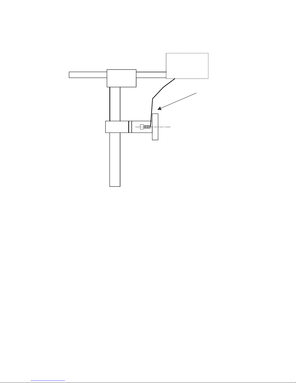
GROUNDING STRAP INSTALLATION
INSTALL STRAP
UNDER 5/16”
SCREW. E
CONDUCTIVITY TO
EARTH GROUND IS
LESS THAN 1 OHM
NSURE
INPUT POWER CONNECTION AND MODIFICATION
Insert the power plug to the available power source. The supplied power supply
will is universal and will auto detect 100/240 VAC 50-60hZ.
No other adjustments are necessary.
3 EVOLUTION 1 SYSTEM MANUAL Issue 1.4 16 May 2006
Page 6
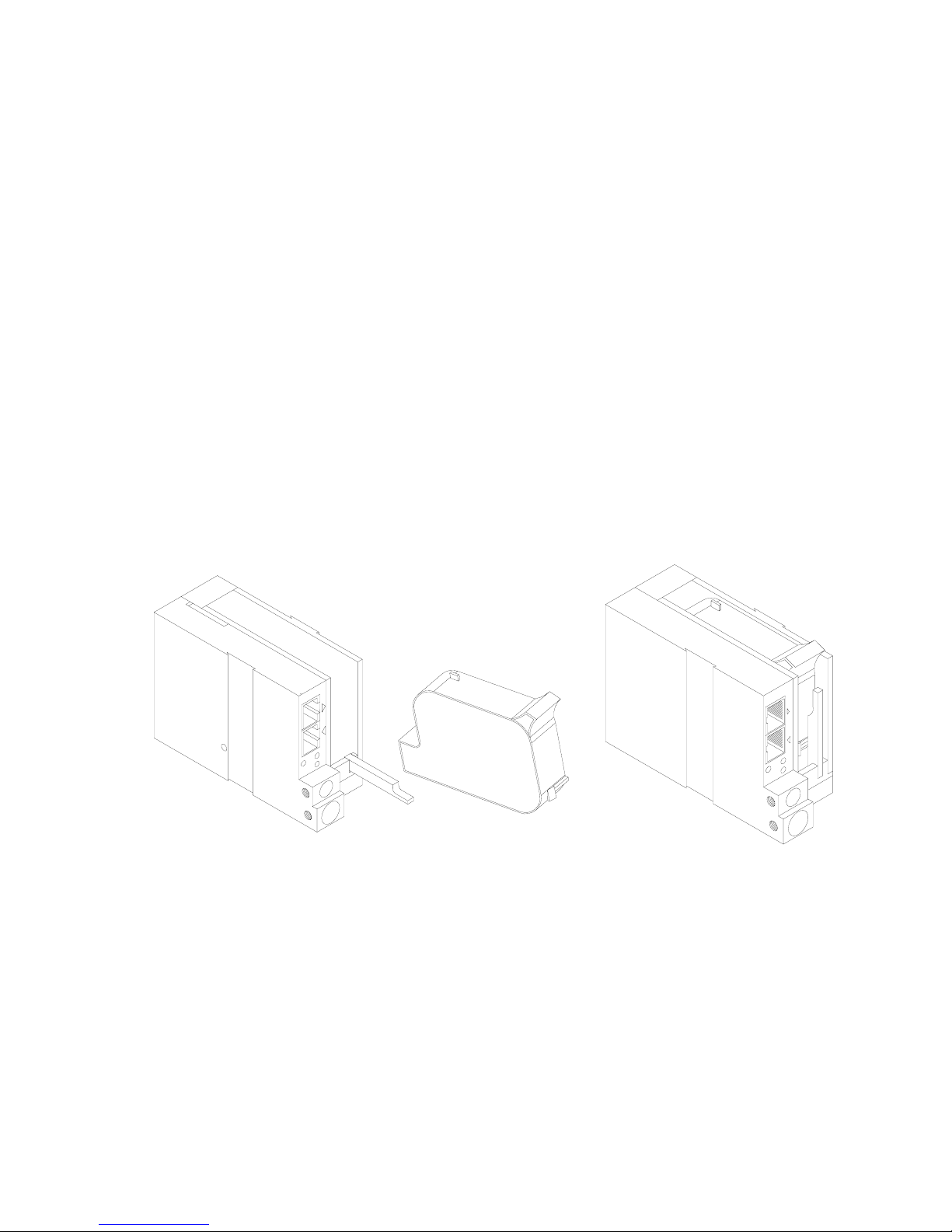
INSTALLING THE PRINT CARTRIDGE
Remove the protective film from the face of the print head and retain the film.
This protective film may be re-applied to store partially used cartridges. If it is
necessary to remove the print head and store for a long period of time, it is best
to re-apply the plastic film, and place the cartridge in a closeable plastic bag.
Rotate the Print Head Release mechanism to the rear of the print head so that it
is free for insertion of the print cartridge. Push the print cartridge in and down to
insert it into the print carriage. Gently lift the locking arm and press forward
against the print cartridge. A snap will be felt as the locking mechanism presses
the cartridge into the correct position.
NOTE: EACH PRINT CARTRIDGE HAS BEEN PROFILED
AT THE FACTORY. THIS PROCEDURE DETERMINES
THE OPTIMAL OPERATING CHARACTERISTECS FOR
EACH INDIVIDUAL CARTRIDGE. USING ANY OTHER
PRINT CARTRIDGE WILL HAVE UNDESIRABLE
RESULTS.
NOTE: WHEN A NEW CARTRIDGE IS INSTALLED,
BOTH THE RED AND GREEN LIGHT WILL FLASH
TWICE INDICATING A CORRECT INSTALLATION.
THE USER MUST REMEMBER TO RESET THE INK
LEVEL UNDER THE F4 FUNCTION KEY.
4 EVOLUTION 1 SYSTEM MANUAL Issue 1.4 16 May 2006
Page 7
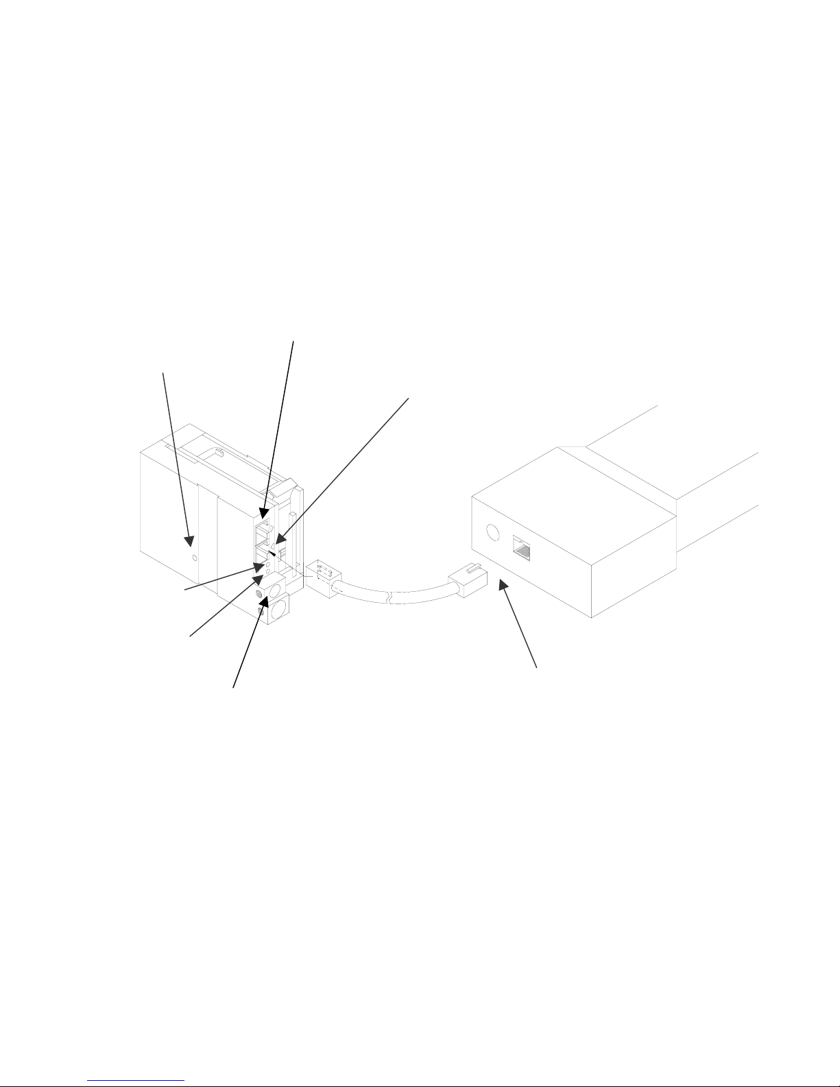
CONNECTING THE CONTROLLER TO THE CARRIAGE
Connect the Controller to the print carriage using the supplied 3 FT (.9 mm)
interconnect cable C21008-3 supplied with the Printing System. The cable is a
standard RJ50 (10 conductor). Longer cables are available as required.
Connect either end of the cable to the Carriage Assembly and securely lock in
place. NOTE: THE CONNECTOR MUST BE PLUGGED INTO THE INPUT RJ50
CONNECTOR LOCATED ADJACENT TO THE LED’S AND MARKED WITH
AN ARROW POINTING TO THE CONNECTOR. A click will be heard when the
connector is in the appropriate position. Connect the free end to the Controller
Assembly and ensure connector is securely seated.
PRINT CARRIAGE RJ50
RESET
SWITCH
ACCESS
HOLE
OUTPUT CONNECTOR
PRINT CARRIAGE RJ50
INPUT CONNECTOR
GREEN
CYCLE LED
RED PRINT
ENABLE LED
CONTROLLER RJ50
POWER INPUT
+12VDC @1.5A
CONNECTOR
CAUTION:
NOTE ORIENTATION OF THE CONNECTORS. DO NOT FORCE
CONNECTORS INTO POSITION SECURELY LATCH (CLICK) INTO
POSITION.
CONTROLLER MUST PLUG INTO THE PRINT CARRIAGE RJ50 INPUT
CONNECTOR FOR PROPER OPERATION. THE PRINT CARRIAGE RJ50
OUTPUT CONNECTOR IS USED EITHER FOR CONNECTION TO THE NEXT
PRINTER ON A NETWORK OR FOR EXTERNAL PRODUCT OR EXTERNAL
ENCODER INPUT.
THE POWER INPUT CONNECTOR MUST BE SECURELY INSERTED INTO
THE PRINT CARRIAGE. UPON PROPER INSERTION BOTH THE RED AND
GREEN LED’S WILL FLASH INDICATING PROPER CONNECTION.
5 EVOLUTION 1 SYSTEM MANUAL Issue 1.4 16 May 2006
Page 8

CONFIGURING THE PRINTER
To verify the current operating software press the STOP PRINT
key.
Press the V key
CONTROLLER 7.08
PRINTER 2.08J
PRINTER SN XXXXXX
EXIT ANY KEY
The first line indicates the version of the controller software
The second line numerics indicate printer software version and the letter is the
firmware version of the printer. The ‘+’ (s) following indicate options installed:
+ _ _ _ = Option 1
_ _ + _ = Option 1.5
+ _ + _ = Option 1 and Option 1.5
+++ _ = Option 2
++++ = Option 3
The third line indicates the serial number of the printer
SYSTEM RESET
There are two types of resets available in the Evolution printing system. The first
type of reset is a SOFT RESET.
ERASE STORED
MESSAGES
YES OR NO Y/N
RESET PRINT HEAD
YES OR NO Y/N
ALL HEADS
WILL BE RESET
CONTINUE = X KEY
ANY OTHER EXITS
Depressing the R key while applying power to the
unit will display the reset command mode
CAUTION: A response of Y will delete all stored
messages.
The next screen to appear prompts the user to
determine if a print head is to be restored to its
default value.
CAUTION: ALL PRINT HEADS CONNECTED
TO THE CONTROLLER WILL BE RESET TO
FACTORY DEFAULT CONDITIONS. THIS
INCLUDES RESETING EACH UNIT ADDRESS
TO 1. TO PREVENT THIS REMOVE ALL
INTERCONNECTED PRINT HEADS EXCEPT
FOR THE UNIT TO BE RESET FROM THE
DATA LINK.
6 EVOLUTION 1 SYSTEM MANUAL Issue 1.4 16 May 2006
Page 9
The second reset is a hard reset. Disconnect the power cable. Insert a standard
paper clip into the hole on the female dovetail side of the cabinet, and while
holding the paper clip in place (a light click will be felt) re-apply the power
connector.
This operation will reset the print carriage assembly to the factory default settings
and clear any current message.
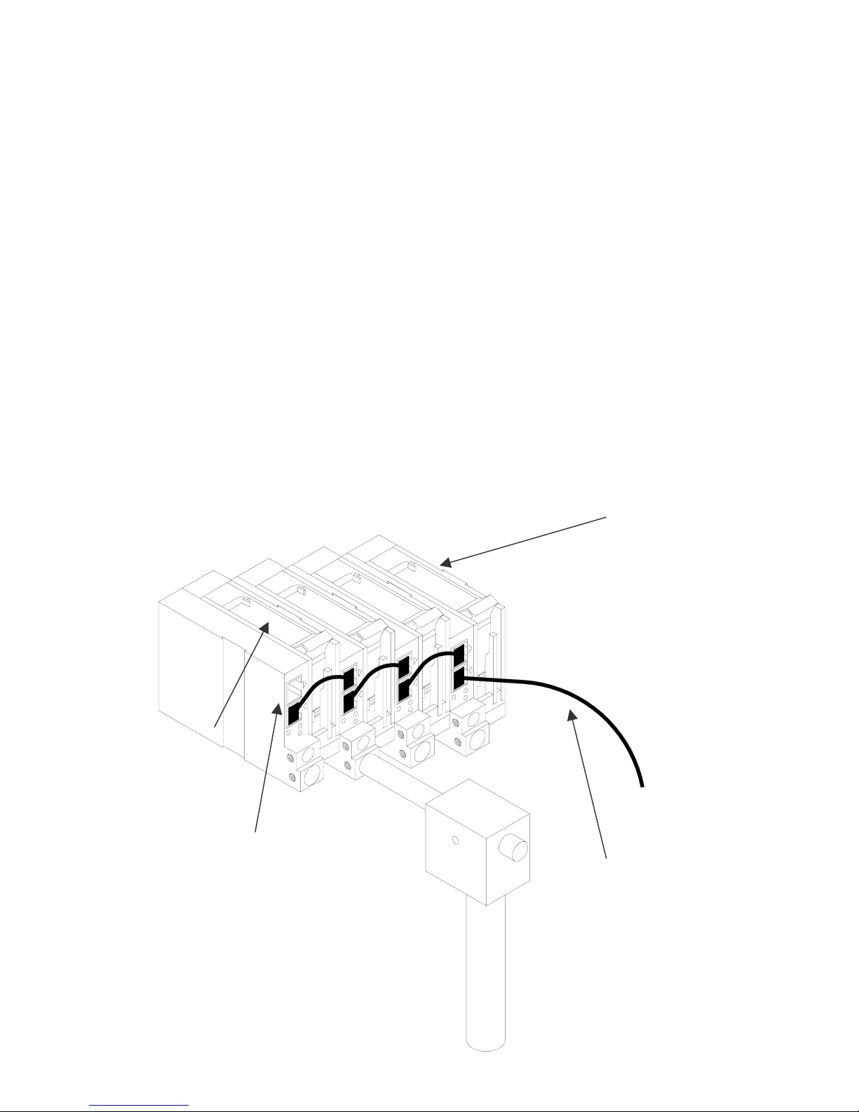
MULTIPLE PRINT HEADS
EVOLUTION 1 printing systems have the ability to reside on a network. The
network may contain from 1 to 32 print carriages connected via RJ50 cables.
These cables are available in varying lengths depending on the application.
Each mounting bracket can support up to 4 print carriages and would typically
interconnect with a 6” RJ50 data cable.
NOTE: Please address each unit individually as per page 2-17 prior to daisy
chaining the printers. Special care must be taken to connect the output of the
first print carriage to the input of the next print carriage.
When connecting multiple print carriages place no more than 2 stations on a side
of the mounting bracket as shown.
PRINT CARRIAGE
ADDRESS 4
PRINT CARRIAGE
LOCKING SET
SCREW
PRINT CARRIAGE
ADDRESS 1
TO
CONTROLLER
OR COMPUTER
DATA LINK
7 EVOLUTION 1 SYSTEM MANUAL Issue 1.4 16 May 2006
Page 10
EVOLUTION 1 QUICK START
Connect the printer carriage to the appropriate
STOPPED
HD 1- - >SPEED=120
EVOLUTION 1
power source.
Connect the controller to the carriage assembly.
The controller derives power from the carriage.
On startup the LCD will display as pictured.
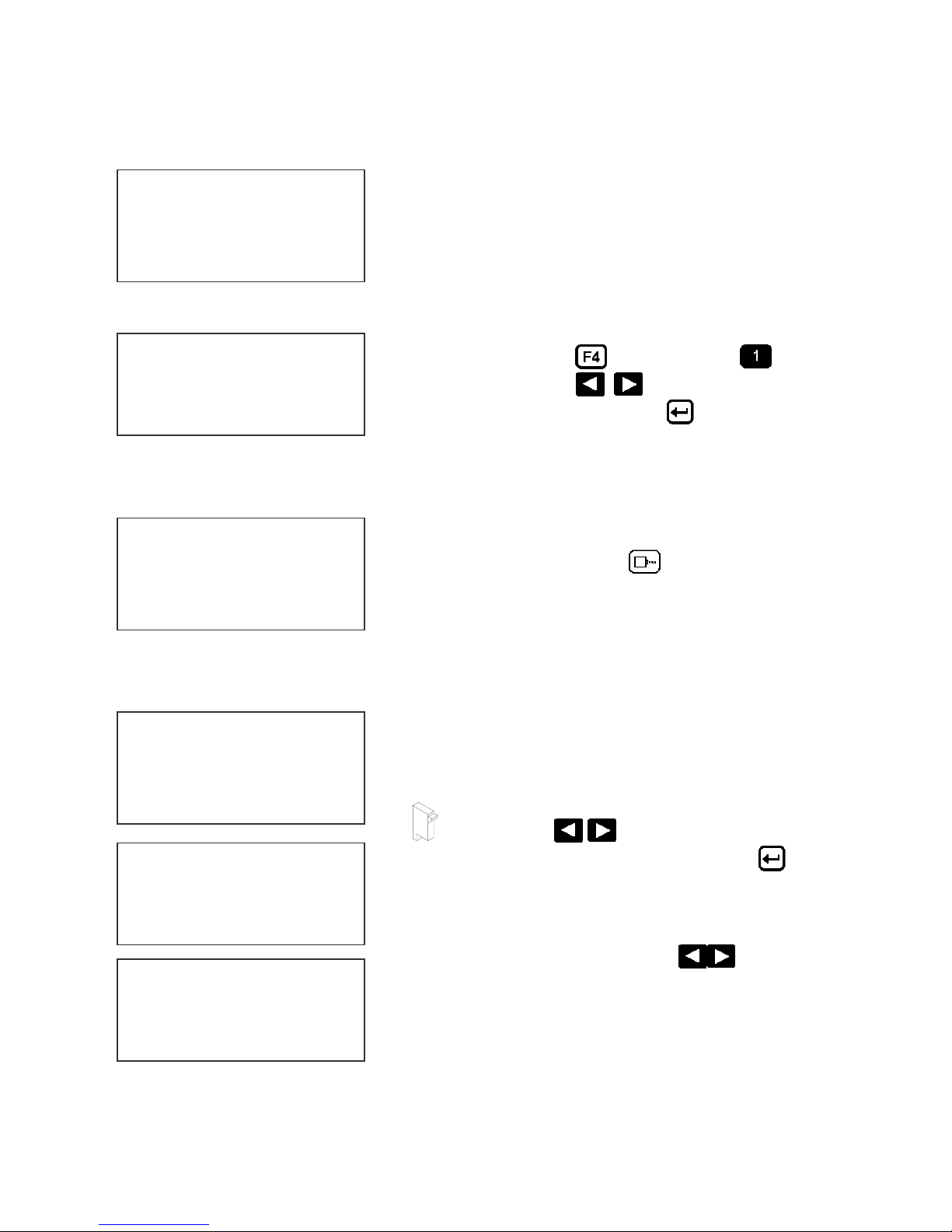
CHANGING LANGUAGE PROMPTS
< - - SELECT - - >
ENGLISH
Press the F4 key
LANGUAGE. Use the
desired language and press the
language.
ENABLING PRINT MODE
PRINTING
HD 1- - >SPEED=120
EVOLUTION 1
Press the GREEN PRINT key to start printing
HEAD SELECT MODE
STOPPED
HD 1- - >SPEED=120
The hand held controller can program up to 32 print
carriages on an RS485 data link. The factory default
sets each print carriage to ADDRESS 1. Selection
of another print head other than ADDRESS 1, press
EVOLUTION 1
and select for
keys to select the
to select the
< - - SELECT - - >
WHICH HEAD = 1
NO RESPONSE
ANY KEY TO EXIT
8 EVOLUTION 1 SYSTEM MANUAL Issue 1.4 16 May 2006
the
alternate print carriage number and press the
key. The print carriage whose address was selected
will respond with the current message and
appropriate parameters.
As an added convenience using the
scan to find the next available head connected to
the environment
Accessing an address not associated with any print
carriage will result in a no response message.
key. Use the keys to select the
will auto
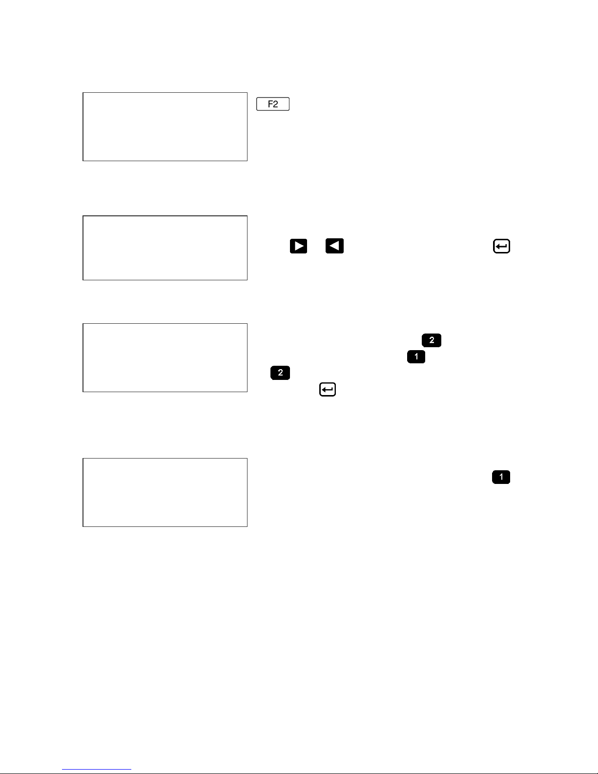
Page 11

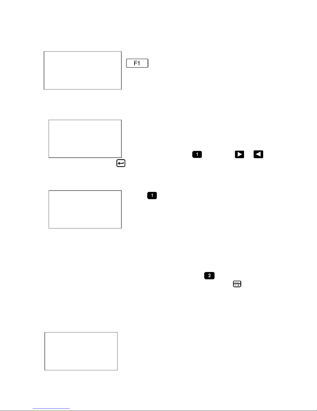
ENTERING A MESSAGE
STOPPED
HD 1- - >SPEED=120
EVOLUTION 1
MESSAGE ENTRY
FONT 1 LINE
EVOLUTION 1
MESSAGE ENTRY
FONT 1 LINE
MESSAGE ENTRY
FONT 1 LINE
EXP 12/10/04
PRINTING
HD 1- - >SPEED=120
EXP 12/10/04
Press the GREEN PRINT key
The LCD display will change from PRINTING to
STOPPED.
Press the GREEN EDIT key
Press the BLUE F3 key
message
Press the BLUE FONT key to select
the desired font size and enter the text EXP
12/10/04
Press the ENTER key
EDIT mode
Press the GREEN print enable key to enter
the print mode
to end the MESSAGE
to delete the entire
9 EVOLUTION 1 SYSTEM MANUAL Issue 1.4 16 May 2006
Page 12
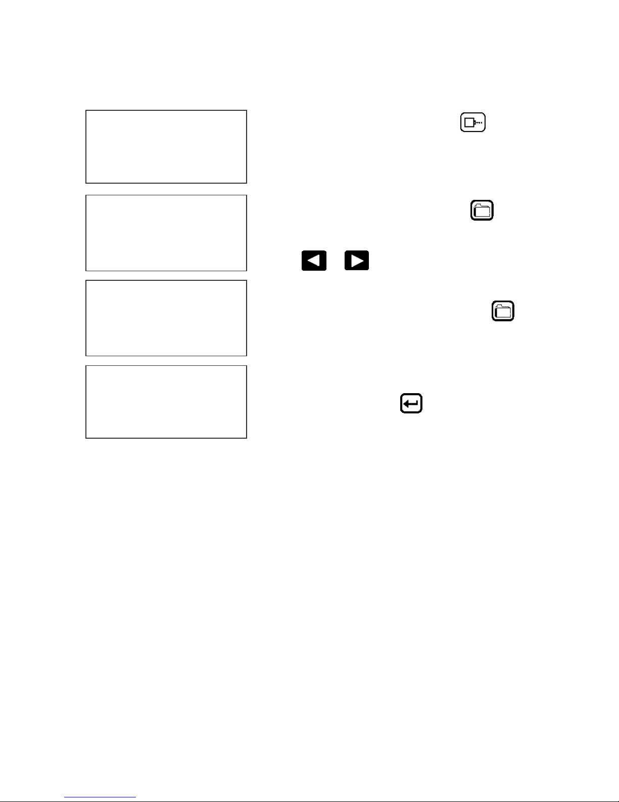
STORING A MESSAGE (OPTION PACK 1, 1.5, 2 OR 3)
STOPPED
HD 1- - >SPEED=120
EXP 12/10/04
MESSAGE # 1
PLEASE WAIT
MESSAGE # 1
MESSAGE STORED
EXP 12/10/04
STOPPED
HD 1- - >SPEED=120
EXP 12/10/04
Press the GREEN STOP PRINT KEY
Note: In option pack 1 there is a
maximum of 50 messages stored.
Option pack 1.5 increases message
storage to 99 messages.
Press the RED MESSAGE STORE key
The LCD display will display the message storage
screen
Use the
location
Press the RED MESSAGE STORE KEY
second time and the current message appears in
the selected location and is stored.
Press the ENTER key
command prompt.
or to select the desired storage
a
to return to the
10 EVOLUTION 1 SYSTEM MANUAL Issue 1.4 16 May 2006
Page 13
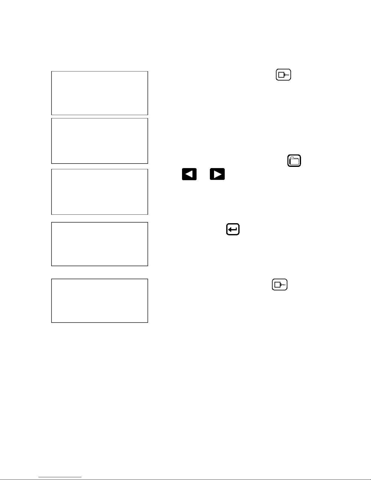
LOADING A MESSAGE ((OPTION PACK 1, 1.5, 2 OR 3)
STOPPED
HD 1- - >SPEED=120
EVOLUTION 1
MESSAGE # 1
PLEASE WAIT
MESSAGE # 1
EXP 12/10/04
STOPPED
HD 1- - >SPEED=120
EXP 12/10/04
Press the GREEN STOP PRINT KEY
Note: In option pack 1 there is a
maximum of 50 messages stored.
Option pack 1.5 increases message
storage to 99 messages.
Press the RED MESSAGE STORE key
use the or keys to select the desired
message
and press the ENTER
key
and
PRINTING
HD 1- - >SPEED=120
EXP 12/10/04
Press the GREEN print enable key
the print mode
to enter
11 EVOLUTION 1 SYSTEM MANUAL Issue 1.4 16 May 2006
Page 14
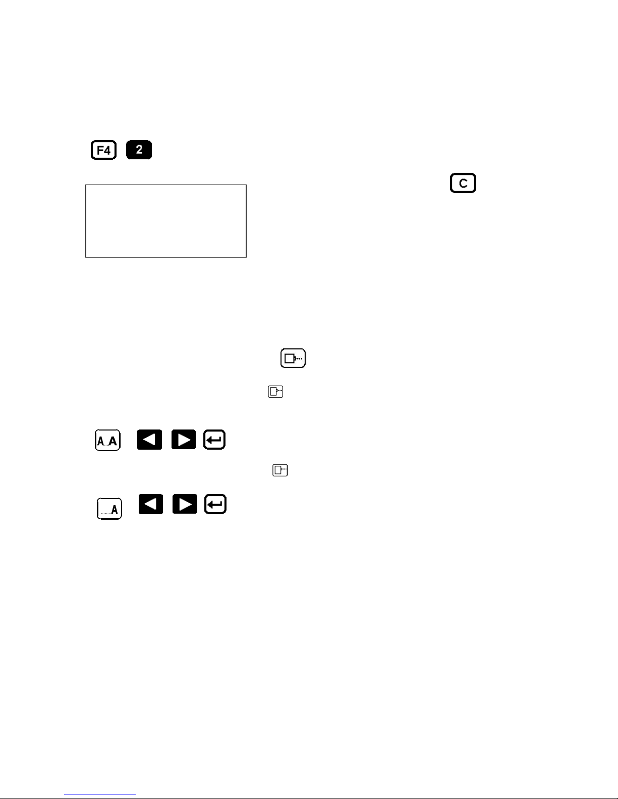
EVOLUTION 1 QUICK SETUP
Install a new cartridge. Press the following keys in order:
REMAINING INK
100 %
C NEW CARTRIDGE
OTHER KEY EXIT
Each time a new print cartridge is installed the system automatically profiles the
correct operating parameters for the new cartridge. These parameters set the
required voltage and on time to produce consistent results without user
intervention..
NOTE: USING OTHER THAN AUTHORIZED CARTRIDGES MAY CAUSE
UNDESIRABLE RESULTS.
Press the GREEN print enable key
To set the LINE SPEED, press to put the system in the Printing mode. Set
character width by
To set the PRINT DELAY press: to put the system in the Printing mode. Set
print delay by
To reset the ink level detector press
to enter the print mode
. NOTE: Each increment or decrement changes the delay by the pre-defined
amount.
You may continue to experiment with line speed and print delay until the desired
code registration on the product is achieved.
12 EVOLUTION 1 SYSTEM MANUAL Issue 1.4 16 May 2006
Page 15

PART 2: OPERATION PROCEDURES
CONTENTS
OVERVIEW 2-2
Controller and LCD 2-2
Keypad Key Descriptions 2-3
Turning on the Print Station for the First Time 2-4
Checking System and Font information 2-4
Changing System Time and Date (OPTION PACK 2) 2-5
PROGRAMMING 2-6
Definitions and Modes of Operation 2-6
Menu Structure 2-7
F1 Menu 2-8
Character Spacing 2-8
External Encoder 2-8
Date Offset (OPTION PACK 3) 2-8
F2 Menu 2-9
Direction 2-9
Print Inverse 2-9
Product Detect 2-9
Auto Repeat (OPTION PACK 1 OR 2) 2-10
F3 Menu 2-11
Product Counter (OPTION PACK 3) 2-11
Shift Code (OPTION PACK 3) 2-12
Format Date (OPTION PACK 2) 2-13
Format Time (OPTION PACK 2) 2-14
F4 Menu 2-15
Change Language 2-15
Ink Supply 2-15
Set Unit Address 2-16
Load Card Fonts-Logos-Optional Software 2-17
SETTING UP LINE SPEED AND PRINT DELAY 2-20
Setting Line Speed 2-20
Setting Print Delay 2-21
INPUT, EDIT AND DELETE MESSAGES 2-22
Editing Messages 2-22
PASSWORD PROTECTION (OPTION PACK 1 OR 2) 2-24
MESSAGE STORAGE (OPTION PACK 1, 1.5 OR 2) 2-25
Storing a Message 2-25
Recalling A Stored Message 2-25
1 EVOLUTION 1 SYSTEM MANUAL Issue 1.4 16 May 2006
Page 16
OVERVIEW
CONTROLLER AND LCD
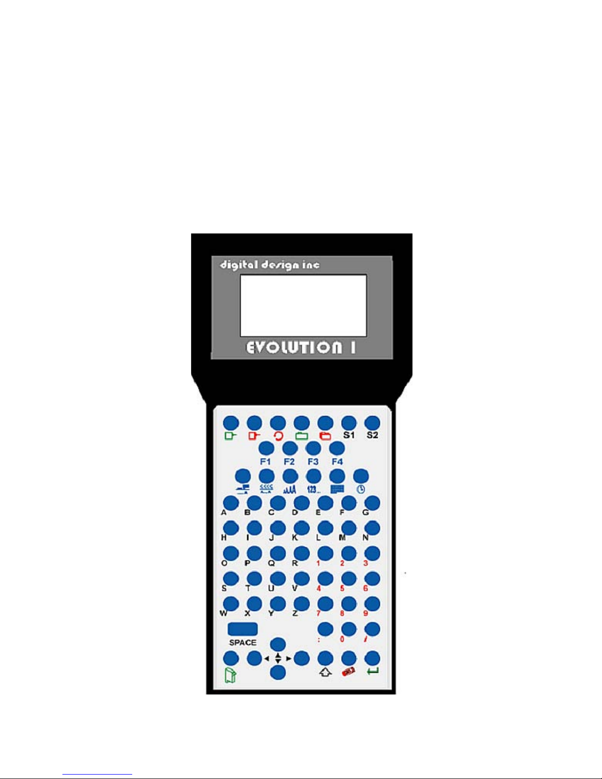
The keypad on the print station, pictured here, contains 64 keys. The LCD will
display various messages to assist in programming on the upper half of the
display. The lower half of the display will show up to two lines of the entered
print message.
The 4 keys on the top row are the function keys F1 through F4. They each
consist of submenus for modifying various printer functions. Their specific
menus are detailed later in this section.
.
STOPPED
HD 1 - ->SPEED= 120
EVOLUTION 1
2 EVOLUTION 1 SYSTEM MANUAL Issue 1.4 16 May 2006
Page 17
KEYPAD KEY DESCRIPTIONS
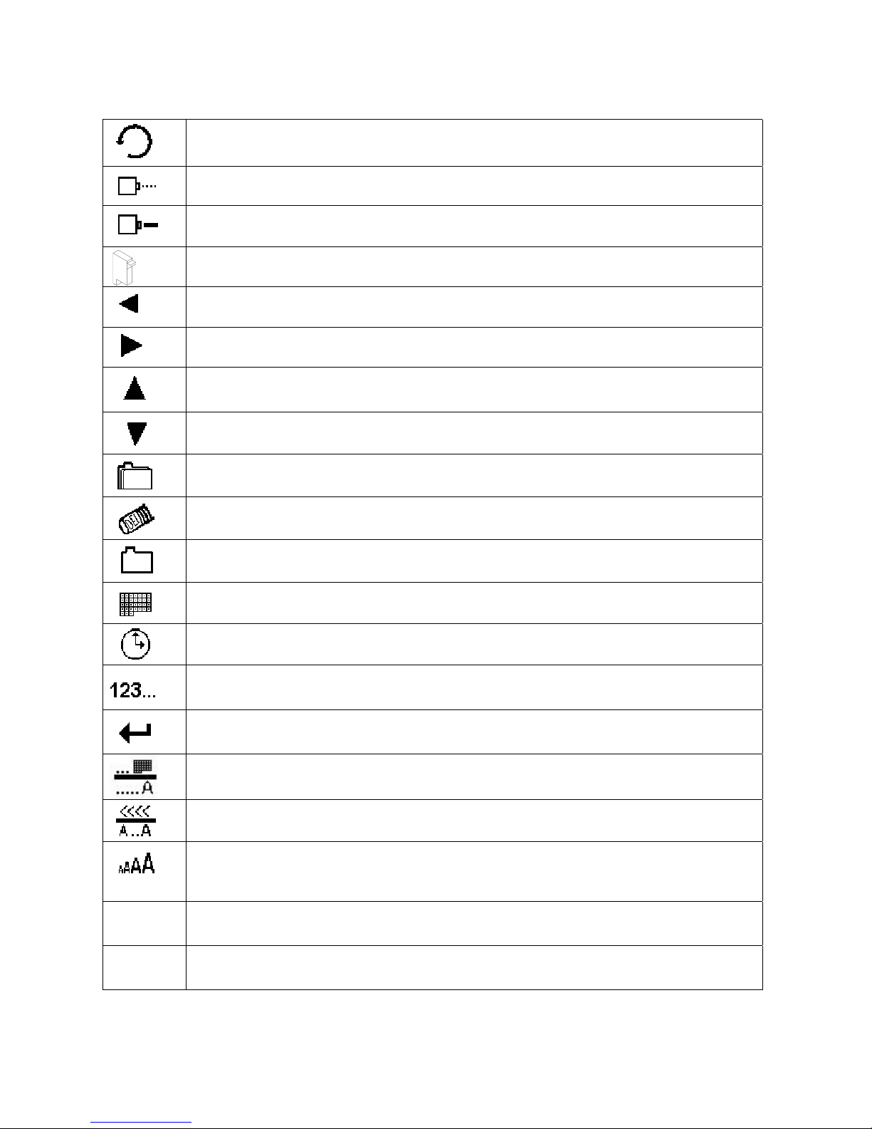
This is the manual cycle key. When in the Stopped mode, pressing this
key causes the printer to print one code
.
This is the Print key. Use it to place the unit in the Print mode
This is the Purge key. Use it to purge ink for maintenance purposes. The
unit must be in the Command mode to use this key.
This is the Head Select key. Use it to select the address of the head to be
S1
communicated with.
Use this arrow to decrease values, and use it to move the cursor in the
message line while editing the message.
Use this arrow to increase values and use it to move the cursor in the
message line while editing the message.
Use this arrow to move the cursor between the message lines while in
Edit mode and building a message.
Use this arrow to move the cursor between the message lines while in
Edit mode and building a message.
This key is the Message Storage key. Use it to store and to recall
individual codes.
This is the Delete key. Use it to backspace to delete a character when
mistyped as well as to exit from certain menus.
This is the Message Entry key. Use this key to enter the Message Entry
mode, to input a code or to edit a code.
This is the Date key. Use this key to enter the Date in Message Entry
Mode. (OPTION PACK 2). Change Date in STOPPED mode.
This is the Time key. Use this key to enter the Time in Message Entry
Mode. (OPTION PACK 2). Change Time in STOPPED mode.
This is the Sequence Number key. Use this key to enter the Sequence
Number in Message Entry Mode. (OPTION PACK 2)
This is the Enter or Return key. When pressed, the unit will accept input
and exit certain menus.
This key selects the Print Delay in COMMAND mode and Offset Date in
EDIT mode (OPTION PACK 3)
This key selects the Line Speed in COMMAND mode and the shift code in
the EDIT mode (OPTION PACK 3)
This key selects the Font size in the EDIT mode.
In the COMMAND mode pressing this key displays the current fonts
loaded in the print head.
Pressing this key while in the Message Entry mode accesses special
characters
S2
3 EVOLUTION 1 SYSTEM MANUAL Issue 1.4 16 May 2006
This key is reserved for special customer Logos
Page 18

TURNING ON THE PRINT STATION FOR THE FIRST TIME
To turn the print station on insert the power jack into
STOPPED
HD1- - >SPEED=120
EVOLUTION 1
information regarding the system:
The Top line indicates the operating mode of the unit: “STOPPED” when in
Command mode, “ PRINTING” when in Print mode, and “MESSAGE ENTRY
when in message entry.
The 2
product and the programmed SPEED.
The lower half two lines of the display shows the message entered for printing.
This may represent one or two lines of code.
nd
line shows the print head currently selected, the direction of travel for the
the DC power connector.
There is no on/off switch.
The first time the print station is turned on, as
received from the factory, the LCD will look like the
illustration on the left. Each line gives important
CHECKING SYSTEM INFORMATION
CONTROLLER 7.08
PRINTER 2.08J +++
PRINTER SN284955
ANY KEY TO EXIT
pack 1, the second + indicates option pack 1.5 and the last + indicates option
pack 2.
Verify system information by pressing the V key
on the hand held controller keyboard. The LCD
screen will display the software, firmware, serial
number and options enabled. Enabled options
are indicated on the second line as a series of +
characters where the first + indicates option
CHECKING LOADED FONTS
ACTIVE FONTS
2 LINE fontname
1 LINE fontname
ANY KEY TO EXIT
Press the FONT key in the COMMAND
mode to check what fonts are currently loaded
in the print head.
4 EVOLUTION 1 SYSTEM MANUAL Issue 1.4 16 May 2006
Page 19

CHANGING SYSTEM DATE (OPTION PACK 2 INSTALLED)
PRESENT SETTING
ANY CHANGES Y/N
01/04/00
PRESENT SETTING
ANY CHANGES Y/N
01/04/00
ENTER MONTH-
PRESENT SETTING
ANY CHANGES Y/N
04/23/05
When the unit is in the STOPPED mode
pressing the DATE key allows the user to
change the system date. If there are no
changes press the N key to return to the
STOPPED mode.
Press the Y key to change the date.
The system will prompt the user first for the
Month (enter 2 digits), then the Day (2 digits)
and finally the year (2 digits).
After the data is entered the system displays
the currently entered date and pressing the N
key returns the user to the STOPPED mode,
or press Y to the correct the date.
CHANGING SYSTEM TIME (OPTION PACK 2 INSTALLED)
Select the N key if the time is correct and
PRESENT SETTING
ANY CHANGES Y/N
23:05
PRESENT SETTING
ANY CHANGES Y/N
23:05
ENTER HOURS -
PRESENT SETTING
return to the STOPPED mode.
Press the Y key to change to the correct time.
Enter the correct hours (2 digits) followed by
the correct minutes (2 digits). The screen
displays the corrected time. Press the Y key to
make further changes or N key to return to the
STOPPED mode.
Notice the time is in 24-hour format.
ANY CHANGES Y/N
13:50
5 EVOLUTION 1 SYSTEM MANUAL Issue 1.4 16 May 2006
Page 20

PROGRAMMING
DEFINITIONS
There are two parts to programming the EVOLUTION 1 ink jet printer,
• Setting the operations parameters, (character width, delay, etc.) and
• Building the message.
MODES OF OPERATION
The system operates is 3 basic modes. They are: Print Mode, Command Mode,
and Message Entry Mode.
In Print Mode the majority of the keys on the keypad are disabled to avoid
inadvertent changes. When in Print Mode the Top line of the LCD will display
PRINTING.
The Command Mode is used to change the functions of the printer. When in the
Command Mode the display will show STOPPED on the top line.
The Message Entry Mode is used to create or modify printable codes, when in
this mode the top line of the display will show MESSAGE ENTRY.
PRINT MODE AND STOPPED “COMMAND” MODE
PRINTING
HD1- - >SPEED=120
EVOLUTION 1
STOPPED
HD1- - >SPEED=120
EVOLUTION 1
Mode. To enter Command mode, press
When in the Print mode the screen will look like
the screen on the left. When PRINTING is seen
on the LCD, the unit will print as product passes in
front of the carriage assembly. To enter Print
mode, press
When in the Command Mode the screen looks like
the illustration at left. When STOPPED the printer
will not print when product is moved past the
carriage assembly.
In Command mode, access can be made to the
menus under the function keys, F1 through F4
icon control keys plus access to Message Entry
.
.
6 EVOLUTION 1 SYSTEM MANUAL Issue 1.4 16 May 2006
Page 21
MENU STRUCTURE
In the Command mode, access is allowed to the menu structure for basic
parameters. The menus reside within the function keys, F1 through F4. In order
to select one of the parameters, press the number key that corresponds to the
desired parameter.
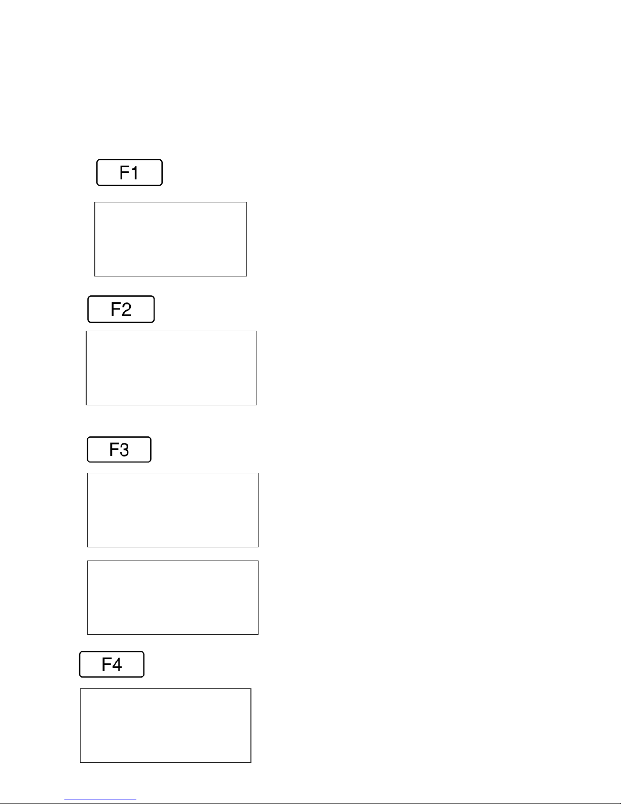
The F1 key, when pressed, brings up the menu as shown below.
1=CHAR. SPACING
2=EXT. ENCODER
3=DATE OFFSET
The F2 key, when pressed, brings up the menu as shown below.
1=DIRECTION
2=PRINT INVERSE
3=PRODUCT DETECT
4=AUTO REPEAT
The F3 key, when pressed, brings up the menu as shown below.
NOT AVAILABLE
ANY KEY TO EXIT
1= PRODOCT COUNT
2= SHIFT CODE
3=DATE FORMAT
4=TIME FORMAT
The F4 key, when pressed, brings up the menu as shown below.
#3 VALID IN OPTION PACK 3 ONLY
SCREEN WITHOUT OPTION PACK 2 OR 3
INSTALLED
#1 VALID IN OPTION PACK 3 ONLY
#2 VALID IN OPTION PACK 3 ONLY
#3 VALID IN OPTION PACK 2 OR 3
#4 VALID IN OPTION PACK 2 OR 3
1=LANGUAGE
2=INK SUPPLY
3=SET UNIT I.D.
4=LOAD CARD
7 EVOLUTION 1 SYSTEM MANUAL Issue 1.4 16 May 2006
Page 22
F1 MENU
1=CHAR. SPACING
2=EXT. ENCODER
3=DATE OFFSET
reserved for future system expansion.
Place the unit in the Command mode and press
. The screen shown to the left is produced.
Press the correct number to make changes to that
parameter. Those selections designated as NOT
AVAILABLE will not respond to selection. They are
1 = CHARACTER SPACING:
< - - SELECT - - >
# OF SPACES- 1
This parameter controls the amount of space
between characters in the code. Spacing can be
varied from 1 to 25 columns. Use this control to
make printed codes more legible when code is
change the value. Press
compressed. Press the
once the desired value is displayed.
then press or to
2 = EXT. ENCODER:
ENCODER
1=INTERNAL
2=EXTERNAL
line. The printer can be set to produce a perfect aspect ratio character (300 dpi
vertical and horizontal) or compressed by setting the print head line speed faster
than the actual line speed, or expanded by changing the internal speed slower
than the actual line speed.
In the event there is an acceleration or deceleration to the production line, or
there is a requirement to guarantee accurate aspect ratio, such in the case of
barcodes, an external encoder is necessary. Press
encoder. While external encoder is selected the LINE SPEED key will adjust
the expansion and compression of the printed message. NOTE: WHEN
PRODUCING BARCODES IT IS NECESSARY TO PRODUCE A PERFECT
ASPECT RATIO CHARACTER.
Press to select internal time base. This
parameter controls the source of the time base used
for printing. Each vertical column printed requires a
signal necessary to produce a character
representative of the line speed of the production
to select external
3 = DATE OFFSET: (OPTION PACK 3 ONLY)
This selection is only available with option pack 3
DATE OFFSET
USE KEYS 0->9
# OF DAYS = 100
installed. This allows the user to preset the number of
days used in the date offset calculation to a maximum
of 999 days. The format of the date offset can be
different than a normal date and may be set with the
F3 #3 option DATE FORMAT.
8 EVOLUTION 1 SYSTEM MANUAL Issue 1.4 16 May 2006
Page 23
F2 MENU
Place the unit in the Command mode and press
1=DIRECTION
2=PRINT INVERSE
3=PRODUCT DETECT
4=AUTO REPEAT
produced. Press the correct number to make
changes to that parameter
NOTE: OPTION 4 ONLY APPEARS IF OPTION
PACK 1 IS INSTALLED
. The screen shown to the left is
1 - DIRECTION:
The arrow shown on the LCD’s third line screen
< - - SELECT - - >
LINE DIRECTION
< - - - -
should agree with the direction of product travel.
Press
for the unit to accept the change.
or to change direction. Press
2 - PRINT INVERSE:
CODE ORIENTATION
1 = NORMAL PRINT
This parameter allows the code to print right side
up or upside down. Pressing
the following screen. Press for normal print
will produce
2 = UPSIDE DOWN
on the imprint.
or
by pressing . Look for the change of direction
for upside down codes. Save the choice
3 – PRODUCT DETECT:
PRODUCT DETECT
1 = INTERNAL
2 = EXTERNAL
a portion of the product not directly in front of the print head then an external
product detect sensor must be used. This setting also allows the EVOLUTION 1 to
be controlled from other sources, like a PLC. When external product detect is
selected the user must also change the jumper option within the print head. Refer
to the OPTION SELECT section for proper use.
This menu selection allows the user to select the
source of the product detect feature. Press
to use the internal product detect sensor located
at the front of the print carriage just below the
print cartridge. If it becomes necessary to sense
9 EVOLUTION 1 SYSTEM MANUAL Issue 1.4 16 May 2006
Page 24

4 - AUTO REPEAT: (OPTION PACK 1, 2 OR 3)
< - - SELECT - - >
REPEAT TIME= 0
time delay adds or subtracts a distance equivalent to the pre-defined setting.
Save your choice by pressing
This option enables the unit to continuously print
repeated codes at specified time intervals along
the entire length of the product. A time of 0
disables the Auto Repeat option. Use
or
to change the repeat time. Each number in the
.
10 EVOLUTION 1 SYSTEM MANUAL Issue 1.4 16 May 2006
Page 25

F3 MENU
This menu is reserved for system expansion.
NOT AVAILABLE
ANY KEY TO EXIT
WITH OPTION PACKS INSTALLED
1 – PRODUCT COUNT: (OPTION PACK 3 ONLY)
1= PRODUCT COUNT
2= SHIFT CODE
3=DATE FORMAT
4=TIME FORMAT
Press F3 to change the product count feature.
Each of the following screens prompts the user
to enter the desired format.
NOTE: this is not a printable field.
PRODUCT COUNT
CHANGES Y / N OR C
08:00 - - > 16:00
COUNT = 000000
Enter Y to change the product count start and
end times or N to abort. If the counter is to be
cleared enter the letter C
PRODUCT COUNT
START TIME
08:00 - - > 16:00
ENTER HOURS-
Selecting Y prompts the user to enter the
desired hours-starting time.
NOTE: all times are entered in military time
PRODUCT COUNT
START TIME
08:00 - - > 16:00
ENTER MINUTES-
The next screen prompts for the start time
minutes.
PRODUCT COUNT
END TIME
08:00 - - > 16:00
ENTER HOURS-
PRODUCT COUNT
START TIME
08:00 - - > 16:00
Next the user enters the ending hours time.
NOTE: all times are in military time.
Finally, the ending time minutes are entered.
The product count feature is a non-printable
value and may only be accessed via this menu
function. It will accumulate product counts each
day until the value is cleared using the C key at
the start of the menu option.
ENTER MINUTES-
11 EVOLUTION 1 SYSTEM MANUAL Issue 1.4 16 May 2006
Page 26

2 – SHIFT CODE: (OPTION PACK 3 ONLY)
1= PRODUCT COUNT
2= SHIFT CODE
3=DATE FORMAT
4=TIME FORMAT
ADJUST SHIFTS
< - - SELECT - - >
SHIFT 1 07:00 A
ANY CHANGES Y/N
The shift code option allows the user to enter 6
different shift times per day. Use the arrow keys
to select a shift and enter a Y to change a shifts
start time.
ADJUST SHIFTS
SHIFT 1
START TIME
ENTER HOURS -
Enter the shift starting hours.
Note: all times are in military format
ADJUST SHIFTS
SHIFT 1
START TIME
ENTER MINUTES -
The next screen prompts for the shift starting
minutes.
ADJUST SHIFTS
SHIFT 1
PRINT CODE -
Finally, enter the desired code required to
represent a shift. This may be any
alpha/numeric field. This field will automatically
increment with each shift change.
NOTE: TO DISABLE A SHIFT ENTER A SPACE CHARACTER IN
THE PRINT CODE FIELD. THE SHIFT TIMES WILL BE
DISPLAYED AS --:-- FOR ALL DISABLED SHIFT TIMES.
12 EVOLUTION 1 SYSTEM MANUAL Issue 1.4 16 May 2006
Page 27

3 – DATE FORMAT: (OPTION PACK 2 OR 3)
Press F3 to change the date formatting. Each of
1= NOT AVAILABLE
2= NOT AVAILABLE
3=DATE FORMAT
4=TIME FORMAT
CHANGE FORMAT
1=CALENDAR DATE
2=OFFSET DATE
MONTH FORMAT
1=NUMERIC
2=LETTERS
DATE FORMAT
D=DAY M=MONTH
Y=YEAR J=JULIAN
dm/dd/dy
DATE FORMAT
D=DAY M=MONTH
Y=YEAR J=JULIAN
jjj
DATE FORMAT
D=DAY M=MONTH
Y=YEAR J=JULIAN
jjjyy
return to the STOPPED mode.
MONTH FORMAT
1=NUMERIC
2=LETTERS
the following screens prompts the user to enter
the desired format for printing.
When option pack 3 is installed the user has the
option of selecting a different date format for the
normal printed calendar date and the printed
date offset. Select 1 or 2 to alter the appropriate
date field.
Selecting the standard numeric format will
prompt the user to enter the format of the date in
standard number format.
The default as shipped from the factory is
dm/dd/dy, and may be modified as required.
If the offset format was selected the word DATE
is replaced with the word OFFSET.
To change the format press the delete key and
the last line on the display will be erased. The
entire format will be erased and must be reentered.
Press either of the designator keys (ie M for
month) and the display will display the correct
code for the item selected. As an example enter
the Julian date and year. Press the J key
followed by the Y key. The code entered will
print the Julian date followed by the 2-digit year.
Notice no delimiters were selected, but may
have been entered by selecting the appropriate
key on the keyboard. Press the Enter key to
Alpha characters may have bee selected by
pressing option 2.
13 EVOLUTION 1 SYSTEM MANUAL Issue 1.4 16 May 2006
Page 28

Delete the current formatting by pressing the
DATE FORMAT
D=DAY M=MONTH
Y=YEAR
jjjyy
DATE FORMAT
D=DAY M=MONTH
Y=YEAR
ddmmmyy
Delete key.
NOTE: DELIMITER CHARACTERS
LIKE A / CODE MAY BE ENTERED TO
SEPARATE FIELDS
Enter the desired Date Format and notice when
the M (month) is selected the display shows
mmm. Select the appropriate key on the
keyboard by entering in the desired code. Press
the Enter key to return to the STOPPED mode.
4 – TIME FORMAT: (OPTION PACK 2 OR 3)
Change the Time Format by selecting option 4.
1= NOT AVAILABLE
2= NOT AVAILABLE
3=DATE FORMAT
4=TIME FORMAT
TIME FORMAT
H=HOURS
M=MINUTES
hh:mm
TIME FORMAT
H=HOURS
M=MINUTES
hh
NOTE: Delimiter characters like a :
code may be entered to separate fields
The factory default for time formatting is hh:mm
and may be changed as required. Press the
Delete key and the last line on the display is
erased.
Enter the desired format by pressing the H and or
M keys, and select delimiters as required. Select
H if only hours are required.
Press the Enter key to return to the STOPPED
mode.
14 EVOLUTION 1 SYSTEM MANUAL Issue 1.4 16 May 2006
Page 29

F4 MENU
1 = LANGUAGE
2 = INK SUPPLY
3 = SET UNIT I.D.
4 = LOAD CARD
Place the unit in the Command mode and press
. The screen shown at left is produced.
Press the number that corresponds to the
parameter you wish to change.
1 - LANGUAGE:
Press and the screen will change like the
< - - SELECT - - >
ENGLISH
mode. Whenever language is chosen, all prompts and commands shown on the
screen will be in that language.
one on the left. The default language is English;
the other choice is Spanish. Scroll through the
choices using either or . Once the
desired language is shown on the screen, press
. This will return the unit to the Command
2 - INK SUPPLY:
The second line of the display shows the
REMAINING INK
100
C
NEW CARTRIDGE
ANY KEY TO EXIT
When a C is entered the system automatically profiles the operating conditions
for the new cartridge.
Each cartridge is tested and profiled at the factory eliminating the burden of
personalizing each cartridge by the user. There are a number of tasks associated
with print cartridge profiling, as each print cartridge differs from another. The
correct drive voltage, pulse width timing and pre-fire pulse warming must be
calculated for optimum operation.
percentage of ink remaining in the print
cartridge.
Each time a new cartridge is installed the user
must reset the system ink gauge by pressing the
C key.
NOTE: USING NON-AUTHORIZED CARTRIDGES MAY
PRODUCE UNDESIRABLE RESULTS
15 EVOLUTION 1 SYSTEM MANUAL Issue 1.4 16 May 2006
Page 30

3 – SET UNIT I.D.:
< - - SELECT - - >
SET HEAD # = 1
when adding multiple print carriages to affix a label indicating the unique
ADDRESS number of the individual carriage. To program a carriage it must be
connected directly to the hand held controller, with no other carriages connected.
Each print carriage can contain a unique address
to distinguish multiple carriages when controlled
by a single hand held controller or computer data
link using an RS485 data link. The default for each
new print carriage module is ADDRESS 1.
Addresses can range from 1 to 32. It is advisable
16 EVOLUTION 1 SYSTEM MANUAL Issue 1.4 16 May 2006
Page 31

4 – LOAD CARD:
LOADING FONTS (MENU SELECT 1)
EXECUTE LOADER
1=LOAD FONTS
2=LOAD LOGOS
3=LOAD OPTIONS
LOAD FONT
1= LOAD DEFAULTS
2= LOAD ALTERNATE
LOAD RESULTS
PLEASE WAIT
MEMORY ERROR
NO FLASH CARD
ANY KEY TO EXIT
LOAD RESULTS
2 LINE fontname
1 LINE fontname
ANY KEY TO EXIT
LOAD RESULTS
2 AF fontname
The user can replace the existing FONT, add up
to six logos, or load optional software from a Data
Flash card, which is plugged into the top of the
print carriage. Select 1 to load a different font to
replace the current system font.
The screen to the left will appear and after a few
seconds a result will be displayed to indicate
NOTHING LOADED or the name of the newly
loaded font, logos or software upgrades.
To load or replace the current LOGOS in the
system press the
FONTS the screen at the left will appear indicating
the load results.
This screen will be displayed if the data flash card
is either not present or cannot be read.
CHECK THAT THE DATA FLASH CARD IS
PROPERLY INSTALLED
A successful load will display the current font
names loaded into the print head. This screen will
be displayed when the default fonts are loaded.
When loading alternate fonts the AF will replace
LINE for the alternate font or fonts loaded.
1 AF fontname
ANY KEY TO EXIT
key. Similar to loading
17 EVOLUTION 1 SYSTEM MANUAL Issue 1.4 16 May 2006
Page 32

LOADING LOGOS (MENU SELECT 2)
EXECUTE LOADER
1=LOAD FONTS
2=LOAD LOGOS
3=LOAD OPTIONS
EXECUTE LOADER
PLEASE WAIT
MEMORY ERROR
NO FLASH CARD
ANY KEY TO EXIT
LOAD RESULTS
2 LINE 1 2 3
1 LINE 1 2 3
ANY KEY TO EXIT
LOADING OPTIONS (menu select 3)
EXECUTE LOADER
1=LOAD FONTS
2=LOAD LOGOS
3=LOAD OPTIONS
NOTE: when optional software is loaded into the system the Data Flash
Card is encoded with the serial number of the unit and is valid only for the
unit in which the software was loaded.
CONTROLLER 7.08
PRINTER 2.08I ++++
PRINTER SN284955
ANY KEY TO EXIT
1, the second + indicates option pack 1.5 the third is option pack 2 and the last +
indicates option pack 3.
The user can replace the existing FONT, add up
to six logos, or load optional software from a Data
Flash card, which is plugged into the top of the
print carriage. Select
print head.
This screen will be displayed if the data flash card
is either not present or cannot be read.
CHECK THAT THE DATA FLASH CARD IS
PROPERLY INSTALLED
Displaying the number of logos as indicated in the
pictorial indicates successful loading.
The display indicates the number of logos loaded
for the 1 line or 2 line mode.
Optional software may be added via Data Flash
Card to the basic unit to add features.
Verify system information by pressing the V key
on the hand held controller keyboard. The LCD
screen will display the software, firmware, serial
number and options enabled. Enabled options are
indicated on the second line as a series of +
characters where the first + indicates option pack
to load logos into the
18 EVOLUTION 1 SYSTEM MANUAL Issue 1.4 16 May 2006
Page 33

NOTE: THE FIGURE BELOW SHOWS THE CORRECT
ORIENTATION FOR INSERTING THE DATA FLASH CARD.
INSERT THE DATA FLASH CARD INTO THE
SLOT PROVIDED AT THE TOP OF THE PRINT
CARRIAGE AS SHOWN. NOTE THE
ORIENTATION OF THE LABEL ON THE CARD.
PRESS THE CARD COMPLETELY INTO THE
SLOT. THE CARD SHOULD BE REMOVED
AFTER USE AND STORED IN A SAFE PLACE.
ONCE LOADED (FONTS & OPTIONS) THE CA
IS SECURITY LOCKED WITH THE SERIAL
NUMBER OF THE PRINTER CARRIAGE AND
WILL NOT OPERATE IN ANOTHER PRINT
CARRIAGE.
RD
NOTE:
There are two fonts loaded into the EVOLUTION printer at
any one time. Loading a new font will overwrite the existing font
or fonts. Print starts at the bottom nozzle of the print head (dot
150 for line 2) and at the middle of the print head (dot 75 line 1).
The printer is shipped with a 1/2” font (FONT1 for a single line of
print) and a 7/32” font (FONT0 for two lines of print). The 1/2”
font may be replaced with other than a 1/2” tall character.
Alternate fonts that are loaded replace the existing fonts.
Inserting a data flash card containing alternate fonts and cycling
the power will temporarily use the alternate fonts on the data
flash card until the card is removed and either the power is
cycled or the print station is set to the STOPPED mode. This
eliminates the need to load the alternate font using the LOAD
CARD option.
19 EVOLUTION 1 SYSTEM MANUAL Issue 1.4 16 May 2006
Page 34

SETTING PRINT DELAY AND LINE SPEED
LINE SPEED – This setting adjusts the width of the printer message on the
product. This setting should be adjusted to produce the desired print on the
product. Line speed can be increased or decreased to stretch or compress the
message to fit the desired print area.
PRINT DELAY – This setting adjusts the location of the printed message on the
product.
STOPPED
HD1- - >SPEED=120
EVOLUTION 1
Access to these parameters is possible when the
unit is in either the STOPPED or PRINTING mode
as shown to the left.
Pressing the delay key allows the user
to determine the amount of print delay. Each
PRINTING
HD1- - >SPEED=120
EVOLUTION 1
count at a normal aspect ratio is
approximately 0.060”. This will vary
according the amount of compression or
expansion used.
SETTING LINE SPEED
Normally, the system will be set to use the internal
< - - SELECT - - >
LINE SPEED = 100
this parameter. Once pressed, a new screen appears, as shown to
the left. Changes can now be made by using
character width is 1 to 200. Once the desired number is chosen, press
save your entry.
< - - SELECT - - >
ENCODER DIV = 4
time base for line speed control. The default value is
100, which creates a normal width character on a
line moving at 100 ft per min. The print can be
narrowed by increasing the number and widened by
decreasing the number. Pressing accesses
or . The range of values for
to
If external encoder is enabled and the unit is in the
PRINTING mode the user has the option of
adjusting the compression ratio of the printer
message. Changes may be made by using
. Once the desired number is chosen, press
to save your entry.
or
20 EVOLUTION 1 SYSTEM MANUAL Issue 1.4 16 May 2006
Page 35

SETTING PRINT DELAY
STOPPED
HD1- - >SPEED=120
EVOLUTION 1
is either in the PRINTING or STOPPED mode
PRINTING
HD1- - >SPEED=120
EVOLUTION 1
< - - SELECT - - >
PRINT DELAY= 100
PERFECT ASPECT RATIO CHARACTER. WHEN PRINTING A COMPRESSED
OR EXPANDED CHARACTER THE ACTUAL DIMENSIONAL NUMBER WILL
BE DIFFERENT BUT CAN BE ESTIMATED BASED ON THE 18 COLUMNS
PER COUNT.
NOTE: Setting the line speed first, then adjusting the print delay may prove
to be the best starting point
Print delay is used to position a message on the
product at a location other than at the leading edge.
Access this parameter by pressing
keypad.
NOTE: This parameter may be set when the unit
To change the value use either
range of values for this parameter is 1 to 255. Each
increment represents 18 columns, approximately
.060” (1.5mm). Therefore, a delay of 255 would
approximate 15.3” (388mm). Once a number is
chosen, press
DIMENSION INDICATED IS WHILE PRINTING A
to save the entry. NOTE: THE
on the
or . The
21 EVOLUTION 1 SYSTEM MANUAL Issue 1.4 16 May 2006
Page 36

INPUT, EDIT OR DELETE MESSAGES
STOPPED
HD1- - >SPEED=120
EVOLUTION 1
MESSAGE ENTRY
FONT 1 LINE
EVOLUTION 1
MESSAGE ENTRY
FONT 1 LINE
MESSAGE ENTRY
FONT 1 LINE
EXP 12/01/2004
MESSAGE ENTRY
FONT 2 LINE
BEST BY
EXP 12/01/2004
STOPPED
HD1- - >SPEED=120
BEST BY
To input, delete or edit a message, the unit must be
in the STOPPED Mode. If the LCD reads
PRINTING, press
similar to the one shown at the left.
Enter the Message Entry mode by pressing
The top portion of the screen will change as shown
on the left.
The user has two options to edit or change a
message. If a new message is to be entered press
the
For example, to produce a single line of 1 LINE.
Press until the 1/2 “ font size is shown, and
enter EXP 12/01/2004.
The message shown to the left would be an
example if the 1 LINE font were used.
To place two lines use the to select 2 LINE
size. Press the
Press the
will be entered on. Enter BEST BY. The pictorial at
the left shows two lines of 2 LINE character size. To
enter and print only 1 line of 2 LINE select the line
and enter data to that line only.
Once the message line(s) is complete, save the
change by pressing
key to delete the entire existing message.
EXP 12/01/2004
. The screen should be
.
to delete the entire message.
to select which line the data
.
22 EVOLUTION 1 SYSTEM MANUAL Issue 1.4 16 May 2006
Page 37

MESSAGE ENTRY
FONT 1 LINE
EXP 12/01/2004
MESSAGE ENTRY
FONT 1 LINE
EXP 12/0
MESSAGE ENTRY
FONT 1 LINE
EXP 12/05/2005
MESSAGE ENTRY
FONT 1 LINE
EXP 12/15/2004
< - - SELECT - - >
!#
$&( )*+=¢ŇẾỖ
STOPPED
HD1- - >SPEED=120
EVOLUTION 1
The second option is to replace characters by using
the key or moving the cursor over a character to
be replaced. When the MESSAGE ENTRY mode is
entered the cursor is placed at the end of the line.
Pressing the key will delete the last character on
the line. Successive
last character on a line.
At the left the characters 4 0 0 2 / 1 were deleted.
Enter the correct data, in this case 5/2005.
The alternative approach if just a few characters are
to change is to use the
over the characters to be changed and retype the
correct characters. In this example the 01 was
changed to 15.
Symbols are inserted by pressing
Message Entry mode, position the cursor where a
symbol is needed and press . The screen will
show a line of symbols as presented on the left.
Position the cursor by pressing
special character to be inserted and press
Continue to build the message or press
to the Command mode.
’s will continue to delete the
or to place the cursor
. When in
or on the
.
to return
23 EVOLUTION 1 SYSTEM MANUAL Issue 1.4 16 May 2006
Page 38

PASSWORD PROTECTION (OPTION PACK 1 OR 2)
The EVOLUTION 1 contains a password function
PASSWORD XXXXX
password (which is 12345). Enter the 12345.
ENABLE PASSWORD
YES OR NO Y/N
PASSWORD XXXXX
password.
If the new password is misplaced or forgotten, reset the unit.
designed to limit access to the edit menu and
prevent unauthorized changing of message lines.
To activate this function, switch the unit off, then
press and hold
The display changes and requests the default
The screen to the left appears and prompts the
operator or ENABLE PASSWORD
A response of N maintains the current
password and disables password protection.
If the response Y is selected the screen at the left
appears to prompt the user to enter a new
password. Enter the new 5 character password
any combination of letters and numbers may be
used. Once this has been completed, the unit will
not allow message editing without the entry of the
while switching the unit on.
24 EVOLUTION 1 SYSTEM MANUAL Issue 1.4 16 May 2006
Page 39

MESSAGE STORAGE (OPTION PACK 1, 1.5 OR 2)
STORING A MESSAGE
All EVOLUTION 1 printers are able to store up to 50
MESSAGE # 1
MESSAGE # 1
PLEASE WAIT
MESSAGE # 1
MESSAGE STORED
EVOLUTION 1
NOTE: Message storage should be used after the product has been coded
satisfactorily. When a message is stored all operating parameters of the
printed code are saved. Once recalled, codes will be printed the same as
they had been before.
Option pack 1 enables the user to store up to 50 messages in the hand held
controller. With option pack 1.5 or 2 the controller is capable of storing up
to 99 messages.
system wide programmed messages and their
associated parameters. Follow these steps to store
a message. Create the message and press
Press
message location number.
Press
into that numeric location for recall at a later time.
Use the same procedure to overwrite an existing
stored message as well.
The LCD display will indicate that the message is
stored.
Press
. Using or , scroll to the desired
a second time. This places the message
to exit.
.
RECALLING A STORED MESSAGE
MESSAGE # 1
EVOLUTION 1
STOPPED
HD1- - >SPEED=120
Place the unit in “Stopped” mode and press .
Use the or to scroll through the stored
messages. Find the desired message and press
. That message is now displayed on the screen
ready for printing.
EVOLUTION 1
25 EVOLUTION 1 SYSTEM MANUAL Issue 1.4 16 May 2006
Page 40

PART 3: MAINTENANCE PROCEDURES
CONTENTS
PERIODS OF SHUT-DOWN 3-2
Short Periods of Shutdown 3-2
Long Periods of Shutdown 3-3
PRINT CARTRIDGE MAINTENANCE 3-4
PRINT CARRIAGE MAINTENANCE 3-5
EXPLODED VIEW OF PRINT CARRIAGE 3-5
1 EVOLUTION 1 SYSTEM MANUAL Issue 1.4 16 May 2006
Page 41

PERIODS OF SHUTDOWN
SHORT PERIODS OF SHUT-DOWN
When the printer has been shut down overnight, the system might require a
purge to clear out dust particles that have settled on the nozzle area during nonuse. This is only necessary if there are missing dots in the printed code on
product.
STOPPED
HD1- - >SPEED=120
EVOLUTION 1
PURGING
HD1- - >SPEED=120
EVOLUTION 1
STOPPED
HD1- - >SPEED=120
EVOLUTION 1
PRINTING
HD1- - >SPEED=120
EVOLUTION 1
To purge be sure that the unit is in the STOPPED
Mode by pressing green
changes to STOPPED as shown to left.
Place a piece of lint free wipe (or absorbant paper)
in front of the print head and press the red
Allow the unit to purge for several seconds. There is
an automatic shut down after 1,000 printed columns
to ensure that the print head will not be damaged. If
ink residue has solidified on the nozzle area a small
drop of water may be applied to the lint free wipe.
When purging is complete the LCD will be returned
to the STOPPED mode.
Press the green
PRINTING, as shown at the left. The unit is ready
to begin coding.
and the screen changes to
key. The screen
.
2 EVOLUTION 1 SYSTEM MANUAL Issue 1.4 16 May 2006
Page 42

LONG PERIODS OF SHUT-DOWN
When the printer is to be shut down for extended periods, or the ink cartridge
needs to be changed to insert a different color cartridge, the ink cartridge should
be removed.
Clean the print head nozzle area with a soft, lint free wipes and insure there is no
ink residue remaining on the nozzle area. Re-apply the sealing tape. The print
cartridge may be stored in a sealable plastic bag.
CAUTION: USE THE ORIGINAL SEALING TAPE SUPPLIED WITH
THE EVOLUTION 1 INK CARTRIDGE. DO NOT USE ANY OTHER
MATERIAL OR ANY ADHESIVE BACKED PRODUCT, AS THIS
WILL DAMAGE THE NOZZLE AREA.
3 EVOLUTION 1 SYSTEM MANUAL Issue 1.4 16 May 2006
Page 43

PRINT CARTRIDGE MAINTENANCE
It is necessary to maintain the EVOLUTION 1 print cartridge free from accumulated
dust and debris. Periodically the cartridge should be removed and cleaned. This
is totally dependent on the operating environment and the average printable life
of the ink cartridge. In extremely dusty environments, this maintenance
procedure may be required regularly.
To clean the cartridge, carefully clean the face of the cartridge with a soft, lint
free wipe. Use caution in wiping the NOZZLE area so as not to scratch the face.
Always wipe in the ARRAY PLATE vertically as indicated.
Clean the CONTACT area in a similar fashion.
DIRECTION OF WIPING
4 EVOLUTION 1 SYSTEM MANUAL Issue 1.4 16 May 2006
NOZZLES
CONTACT AREA
Page 44

PRINT CARRIAGE MAINTENANCE
It is necessary to maintain the print head carriage free from accumulated dust
and debris. Periodically the print head carriage should be inspected and cleaned.
This is totally dependent on the operating environment. In extremely dusty
environments, this maintenance procedure may be required occasionally but on
average every week should be sufficient.
Remove the print cartridge and carefully inspect the print carriage C21001 for
dust and debris.
Re-insert the print cartridge and place the unit into the PRINTING mode by
pressing
.
EXPLODED VIEW OF THE C21002 PRINT CARRIAGE
5 EVOLUTION 1 SYSTEM MANUAL Issue 1.4 16 May 2006
Page 45

PART 4: TROUBLESHOOTING AND REPAIRS
CONTENTS
FAULTS 4-2
LCD remains blank 4-2
Unit does not print, although LCD shows information 4-2
Low ink indicator on with full ink cartridge 4-2
Unit does not purge 4-2
Missing one or more dots from code. 4-2
Unit loses data while printing 4-2
1 EVOLUTION 1 SYSTEM MANUAL Issue 1.4 16 May 2006
Page 46

FAULTS
This chart was created to assist the user in troubleshooting the unit. Find the
problem in the first column; apply the remedy(s) suggested in the third column.
Condition Probable Cause Remedy
LCD remains blank. No power.
Ensure the controller is securely
connected to the correct port on
the print carriage assembly
Unit does not print, although
LCD shows information.
Unit in “COMMAND”
No message in unit Input your message (see pages
2-18).
Press
.
mode.
No ink. Replace ink cartridge; reset ink
volume parameter (press
and follow the sequence.
Low ink indicator on with full
ink cartridge.
Did not reset ink volume
parameter.
Press . Continue key
entry following menu prompts.
Unit does not purge. Out of ink. Replace with full ink cartridge.
Reset ink volume parameter
Unit in “PRINTING” mode
(press
Press Stop Print.
).
Ink cartridge clogged Clean Ink Cartridge Nozzle area
with lint free wipe
Missing one or more dots
from code.
No ink. Clean or Replace cartridge and
purge system (press ).
Long down-time. Follow daily start-up procedure if
your line experienced a long
down time.
Unit loses data while printing Static electricity Eliminate source of static.
Attach ground strap between
print head and low impedance
earth ground.
High levels of radio
frequency.
Move unit to an alternate
location or attach ground strap
as above.
Spikes in electrical line. Use AC line filter
2 EVOLUTION 1 SYSTEM MANUAL Issue 1.4 16 May 2006
Page 47

PART 5: PARTS LIST AND OPTIONS
Part No. Description
C21001-1
SPARE PARTS
EVOLUTION 1 Controller Cabinet
C21001-2
C21001-3
C30238
C21002
C21002-7
C21002-8
C21005
C21000-2
96280-01 Floor stand
C21003 Top Coding Mounting Bracket
C21006 External Product Detect
C21007 External Encoder
C21012 Optional Junction Box
EV1-SW1 Option Pack 1 Password, Message Store, Auto Repeat
EV1-SW1.5 Option Pack 1.5 Expanded Message Length
EVOLUTION 1 Controller LCD Assembly
EVOLUTION 1 Controller PCB Assembly
EVOLUTION 1 Controller Keypad
EVOLUTION 1 Print Head Carriage Assembly
EVOLUTION 1 Print Head Carriage CPU Assembly
EVOLUTION 1 Print Head Carriage POGO Assembly
EVOLUTION 1 Mounting Bracket Assembly
EVOLUTION 1 Power supply
OPTIONS
EV1-SW2 Option Pack 2 (Option Pack 1 & 1.5) & Time, Date, Sequential Number
EV1-SW3 Option Pack 3 (Option Pack 2) & Date Offset, Shift Code, Product Count
EV1-FONT Alternate Font (Specify when ordering)
EV1-LOGO Logo Option (Specify when ordering)
C21008-1
C21008-3
C21008-10
C21008-25
C21008-50
C21008-100
CABLES
EVOLUTION 1 RJ50 Cable 6 INCH
EVOLUTION 1 RJ50 Cable 3 Feet
EVOLUTION 1 RJ50 Cable 10 Feet
EVOLUTION 1 RJ50 Cable 25 Feet
EVOLUTION 1 RJ50 Cable 50 Feet
EVOLUTION 1 RJ50 Cable 100 Feet
EVOLUTION 1 SYSTEM MANUAL Issue 1.4 16 May 2006 1
Page 48

INKS
4500BK6 6 Pack of Black Ink Cartridges
4500RD6 6 Pack of Red Ink Cartridges
4500GR6 6 Pack of Green Ink Cartridges
4500BL6 6 Pack of Blue Ink Cartridges
4500YW6 6 Pack of Yellow Ink Cartridges
4500CY6 6 Pack of Cyan Ink Cartridges
4500UV6 6 Pack of Ultra Violet Ink Cartridges
4600BK6 6 Pack of Black Ink Cartridges (SEMI-POROUS)
EVOLUTION 1 SYSTEM MANUAL Issue 1.4 16 May 2006 2
Page 49

PART 6: COMMUNICATIONS PROTOCOL
CONTENTS
DESCRIPTION 6-2
Data Word Definitions 6-2
Baud Rate 6-2
Definitions 6-2
Cabling 6-2
Hardware Interface 6-2
Physical Connections for RS485 6-2
Protocol Format 6-3
SOFTWARE PROTOCOL 6-4
ERROR CODES 6-4
LIST OF COMMANDS 6-5
1 EVOLUTION 1 SYSTEM MANUAL Issue 1.4 16 May 2006
Page 50

DESCRIPTION
This communication protocol is Version 1.4 and was released NOV 2005 and is
used with all EVOLUTION products. The communications option converses with
a host computer via an RS485 data link.
NOTE: EACH REQUEST OR COMMAND SENT TO A PRINT STATION
RECEIVES A RESPONSE FROM THAT PRINT STATION. COMMUNICATIONS
SOFTWARE MUST WAIT FOR A RESPONSE TO DETERMINE IF THE PRINT
STATION WAS READY TO ACCEPT THE COMMAND, AND THE DATA WAS
VALID AND PROCESSED. NO RESPONSE COULD INDICATE THE DATA
WAS LOST. IF AN ERROR WAS DETECTED IN PROCESSING A NAK WITH
AN ERROR CODE IS RETURNED.
DATA WORD DEFINITION
Full Duplex - 7 Data Bits - 1 Even Parity Bit - 1 Start Bit - 1 Stop Bit
BAUD RATE
115,200 Bits per second
DEFINITIONS
Q=QUERY TO HEAD
R=RESPONSE FROM HEAD
D=DATA UPDATE TO HEAD
X=ACK FROM HEAD
‘!’=ASCII CHARACTER OR CHARACTERS
0x21 HEX DATA EQUIVELENT
ADDRESS= TWO ASCII REPRESENTATIONS OF HEX CHARACTERS
CABLING FOR EVLINK ENVIRONMENT
C20552 RS232C to RS485 converter module
C20551 Cable from PC to RS485 converter module
C21008-xxxx Cable (define length) from EVOLUTION units to RS485 data link
C21009 Termination plug for RS485 data link
HARDWARE INTERFACE
When connecting multiple print carriages via an RS485 link, input and output
connectors are provided on the print station, which allows the cabling to be daisy
chained. NOTE: It is important to remember to set each of the print stations to a
unique address.
PHYSICAL CONNECTIONS RS485 PRINT CARRIAGE
Pin # 4 = Receive +
Pin # 5 = Receive Pin # 6 = Transmit +
Pin # 7 = Transmit Pin # 9 = Ground
2 EVOLUTION 1 SYSTEM MANUAL Issue 1.4 16 May 2006
Page 51

Note: At the end of the data link a termination plug is installed to balance the
RS485 data link.
This termination plug connects pin 4 to pin 5 and pin 6 to pin 7. This adds a 120ohm termination resistor across the data lines.
PROTOCOL FORMAT:
Host request for information;
ESC|Command|SOH|EOT (Single End Host to 1 printer)
Or
ESC|STX|Address|Command|SOH|EOT (Multiple printers)
Host sending new information;
ESC|Command|Data|EOT (Single End Host to 1 printer)
Or
ESC|STX|Address|Command|Data|EOT (Multiple printers)
Evolution Printable Character Set
A B C D E F G H I J K L M N O P Q R S T U V W X Y Z
0 1 2 3 4 5 6 7 8 9
Special Symbols:
ASCII Character
Space (0x20) Space
! (0x21) Hour Glass
# (0x23) #
$ (0x24) $
& (0x26) &
( (0x28) (
) (0x29) )
* (0x2a) *
+ (0x2b) +
- (0x2d) . (0x2e) Period
= (0x3d) =
: (0x3a) :
/ (0x2f) /
" (0x22) Cents
% (0x25) Solid block
; (0x3b) Ň
? (0x3f) Ě
@ (0x40) Ó
{ (0x7b} Logo 1
| (0x7c) Logo 2
} (0x7d} Logo 3
NOTE: ALL OTHER CHARACTERS ARE ILLEGAL AND MUST NOT BE SENT
TO THE PRINT HEAD.
Hexadecimal Prints As
3 EVOLUTION 1 SYSTEM MANUAL Issue 1.4 16 May 2006
Page 52

SOFTWARE PROTOCOL
In the following pages, all references to characters or digits pertain to the
standard ASCII character set. The | (bar) character is used as a field separator
and it is not part of the transferred data. When data is shown in hexadecimal, it
will consist of the hex number followed by an H, for example (1BH). All packets to
and from a print station begin with an ESC (1BH) and terminate with an EOT
(04H).
There are two types of commands:
The first sends information to the print station and the second requests
information from the print station.
To distinguish the two types of commands, a SOH (HEX 01) is placed after the
command byte in a request command string. The following illustrates this
concept:
To download data to print station
ESC/GROUP ADDRESS/UNITADDRESS/COMMAND/DATA/EOT
To request data from the Print Station
ESC/GROUP ADDRESS/UNITADDRESS/COMMAND/SOH/EOT
NOTE: EACH REQUEST OR COMMAND SENT TO A PRINT STATION
RECEIVES A RESPONSE FROM THAT PRINT STATION. COMMUNICATIONS
SOFTWARE MUST WAIT FOR A RESPONSE TO DETERMINE IF THE PRINT
STATION WAS READY TO ACCEPT THE COMMAND, AND THE DATA WAS
VALID AND PROCESSED. NO RESPONSE COULD INDICATE THE DATA
WAS LOST. IF AN ERROR WAS DETECTED IN PROCESSING A NAK WITH
AN ERROR CODE IS RETURNED.
ERROR CODES
Commands to a print station, if completed successfully, return a single byte
response of an ASCII ACK (06H). If the command was not successful, a twobyte response of an ASCII NAK (15H) is returned, followed by an error code.
Below is a list of the returned error codes.
NAK 1 = Transmission Error
NAK 2 = Illegal Command Byte
NAK 3 = Trying to print while in command mode
NAK 4 = Trying to read a write only register
NAK 5 = Trying to write a read only register
NAK 6 = Print station buffer full must print before next download to clear
buffer.
NAK 7 = Print station busy with user interaction through local keyboard (i.e. in
edit mode).
NAK 8 = Print station busy.
4 EVOLUTION 1 SYSTEM MANUAL Issue 1.4 16 May 2006
Page 53

COMMANDS:
'!' 0x21 Software Version (read only)
Q. ESC|STX|Address|`!`|SOH|EOT
R. ESC|STX|Address|`PRINTERxxxxxyyyy`|CR|EOT
Where:
PRINTER= ASCII word PRINTER
xxxxx = Software and Firmware versions
(e.g. 2.02H indicates version 2.02 with Firmware version H)
yyyy = Optional Software loaded
Where:
The first y indicates option pack 1
The second y indicates option pack 2
The third y indicates option pack 1.5
The last y indicates option pack 3
The presence of an option pack is indicated by the character
+ (&h2B)
The absence of an option pack is indicated by an ASCII
SPACE (&h20)
'\' 0x5c Unit Serial Number
Q. ESC|STX|Address|`\`|SOH|EOT
R. ESC|STX|Address|`\`|`serial number`|CR|EOT
'B' 0x42 Set Unit Address (Write Only)
D. ESC|STX|Address|`B`|`xy`|EOT
X. ESC|STX|Address|`B`|ACK|EOT
Where: xy = 8 bit unit address
i.e. x = 31 & y = 35 yields unit address 15
'#' 0x23 Printer Configuration (read only)
Q. ESC|STX|Address|`#`|SOH|EOT
R. ESC|STX|Address|`#`|`xy`|EOT
Where: Byte x Bits 3,2,1,0
Bit 3 = if 1 Cartridge Not Valid
Bit 2 = Not Used
Bits 1,0 = System Type
11 = Evolution 1
10 = Evolution 2
01 = Evolution 3
00 = Evolution 4
Where: Byte y Bits 3,2,1,0
0000 = no options available
0001 = option1 enabled
0010 = option2 enabled
0100 = option3 enabled
5 EVOLUTION 1 SYSTEM MANUAL Issue 1.4 16 May 2006
Page 54

'r' 0x52 Remaining Ink (0 to 99%)
Q. ESC|STX|Address|`r` |SOH|EOT
R. ESC|STX|Address|`r`|`ab`|EOT
Where ‘ab’ is a percentage
ESC|STX|Address|’r’|0|0|EOT Resets the ink level
'1' 0x31 Auto Repeat Inter-print delay (0 - 255) – OP1/2/3
Q. ESC|STX|Address|`1`|SOH|EOT
R. ESC|STX|Address|`1`|`ab`|EOT
D. ESC|STX|Address|`1`|`ab`|EOT
X. ESC|STX|Address|`1`|ACK|EOT
0 = Auto Repeat Disabled and each count provides a delay equal to 18
columns of print.
'8' 0x38 Control Flags
Q. ESC|STX|Address|`8`|SOH|EOT
R. ESC|STX|Address|`8`|`xy`|EOT
Where x bits 7,6,5,4,
y bits 3,2,1,0
Bit 0 1 = Enable print mode
Bit 1 1 = Direction forward
Bit 2 1 = External Product Detect
Bit 3 1 = External Encoder
Bit 4 1 = Head busy purging
Bit 5 1 = Head busy manual cycle
Bit 6 1 = Print image inverted
Bit 7 1 = Head busy printing message
D. ESC|STX|Address|`8`|`xy`|EOT
X. ESC|STX|Address|`8`|ACK|EOT
Bit 0 1 = Enable print mode
Bit 1 1 = Direction forward
Bit 2 1 = External Product Detect
Bit 3 1 = External Encoder
Bit 4 Don't Care
Bit 5 Don't Care
Bit 6 1 = Print image inverted
Bit 7 Don't Care
'&' 0x26 Line Speed (RANGE 10-200)
Q. ESC|STX|Address|`&`|SOH|EOT
R. ESC|STX|Address|`&`|`xy`|EOT
D. ESC|STX|Address|`&`|`xy`|EOT
X. ESC|STX|Address|`&`|ACK|EOT
6 EVOLUTION 1 SYSTEM MANUAL Issue 1.4 16 May 2006
Page 55

'd' 0x64 Encoder Divider (Range 0-7)
Q. ESC|STX|Address|`d`|SOH|EOT
R. ESC|STX|Address|`d`|`ab`|EOT
D. ESC|STX|Address|`d`|`ab`|EOT
X. ESC|STX|Address|`d`|ACK|EOT
'’' 0x27 Product Delay (RANGE 1-255)
Q. ESC|STX|Address|`0x27`|SOH|EOT
R. ESC|STX|Address|`0x27`|`xy`|EOT
D. ESC|STX|Address|`0x27`|`xy'|EOT
X. ESC|STX|Address|`0x27`|ACK|EOT
')' 0x29 Inter-Character spaces (RANGE 1-25)
Q. ESC|STX|Address|`)`|SOH|EOT
R. ESC|STX|Address|`)`|`xy`|EOT
D. ESC|STX|Address|`)`|`xy'|EOT
X. ESC|STX|Address|`)`|ACK|EOT
‘j’ Reset Print Head (Write only)
D. ESC|STX|Address|`j`| 96 |CR|EOT
X. ESC|STX|Address|`j`|ACK|EOT
‘G’ 0x47 Errors
Q. ESC|STX|Address|`G`|SOH||EOT
R. ESC|STX|Address|`G`|'xy'|EOT
Where:
Byte x Bits 3,2,1,0
Bit 3 = UART Overrun Error
Bit 2 = Communication Overrun Error
Bit 1 = UART Framing Error
Bit 0 = UART Parity Error
Where:
Byte y Bits 3,2,1,0
Bit 3 = Font checksum error loading from card to chip
Bit 2 = Font 1 checksum error in Ram
Bit 1 = Font 0 checksum error in Ram
Bit 0 = Real Time Clock Memory error
D. ESC|STX|Address|`G`|'xy'|EOT
same bit positions as above
use only as a mask to clear error bits.
i.e. X = 0001 and y = 0100 clears real time clock memory
error and communications overrun error.
X. ESC|STX|Address|`G`|ACK|EOT
7 EVOLUTION 1 SYSTEM MANUAL Issue 1.4 16 May 2006
Page 56

SPECIAL FIELD OBJECTS
Message Objects define special characteristics about the messages
contained in line 1 or line 2. These may define for example font size, sequence
number, date code, etc. There may be up to 15 Objects (special fields) for each
line in a message with the limitation that there can only be 1 sequence number
imbedded in a message.
'P' 0x50 Message Objects
Q. ESC|STX|Address|`P`|SOH|aabbEOT
R. ESC|STX|Address|`P`|'aabbccddeeffgggghhhh' |EOT
Where: aa = objects for which line 0 or 1
bb = number of objects transmitted. (Max 15)
Each object as defined by bb: (repeat the following for each
object)
cc = Position within message string
dd = Number of characters in object
ee = Attribute of the object
Where: ee= 00 Normal Alpha/Numeric character
ee= 01 Time Hours
ee= 02 Time Minutes
ee= 03 Time Seconds
ee= 04 Date Month
ee= 05 Date Day
ee= 06 Date Year
ee= 07 Date Julian
ee= 08 Sequence Number (only 1 per
message)
ee= 09 Barcode
ee= 0A Shift Code
ee= 0B Expiration Date Month
ee= 0C Alpha Date Code
ee= 0D Expiration Date Year
ee= 0E Expiration Date Julian
ee= 0F Expiration Date Day
ff = font of object
Where: ff= 00 for 2 Line Font
ff= 01 for 1 Line Font
gggg = starting column of object in printed image (reserved
hhhh = starting row of object in printed image
D. ESC|STX|Address|`P`|'aabbccddeeffgggghhhh’ |EOT
X. ESC|STX|Address|`P`|ACK|EOT
8 EVOLUTION 1 SYSTEM MANUAL Issue 1.4 16 May 2006
Page 57

'$' 0x24 Line 1 Message (max 24 characters)
Q. ESC|STX|Address|`$`|SOH|EOT
R. ESC|STX|Address|`$`|`message`|CR|EOT
D. ESC|STX|Address|`$`|`message`|CR|EOT
X. ESC|STX|Address|`$`|ACK|EOT
'%' 0x25 Line 2 Message (max 24 characters)
Q. ESC|STX|Address|`%`|SOH|EOT
R. ESC|STX|Address|`%`|`message`|CR|EOT
D. ESC|STX|Address|`%`|`message`|CR|EOT
X. ESC|STX|Address|`%`|ACK|EOT
':' 0x3A Logo1 Name (read only - max 9 characters)
Q. ESC|STX|Address|`:`|SOH|`xy`|EOT
R. ESC|STX|Address|`:`|`logo name`|CR|EOT
Where: x = don’t care
y = Bit 0 = 0 = Logo Name in Font 0
1 = Logo Name in Font 1
Bit 1 = 0 = Get Name from on board data flash chip
1 = Get Name fro Data Flash card
';' 0x3B Logo2 Name (read only - max 9 characters)
Q. ESC|STX|Address|`;`|SOH|xy|EOT
R. ESC|STX|Address|`;`|` logo name `|CR|EOT
Where: x = don’t care
y = Bit 0 = 0 = Logo Name in Font 0
1 = Logo Name in Font 1
Bit 1 = 0 = Get Name from on board data flash chip
1 = Get Name fro Data Flash card
'<' 0x3C Logo3 Name (read only - max 9 characters)
Q. ESC|STX|Address|`<`|SOH|`xy`|EOT
R. ESC|STX|Address|`<`|` logo name `|CR|EOT
Where: x = don’t care
y = Bit 0 = 0 = Logo Name in Font 0
1 = Logo Name in Font 1
Bit 1 = 0 = Get Name from on board data flash chip
1 = Get Name fro Data Flash card
9 EVOLUTION 1 SYSTEM MANUAL Issue 1.4 16 May 2006
Page 58

'G' 0x47 Error Flags (read only)
Q. ESC|STX|Address|`G`|SOH|EOT
R. ESC|STX|Address|`G`|`xy'|EOT
Where Byte x Bits 3,2,1,0
Bit 3 = Not Used
Bit 2 = Font Load error
Bit 1 = Uart Parity Error
Bit 0 = clock chip memory read/write error
Where Byte y Bits 3,2,1,0
Bit 3 = Not Used
Bit 2 = Not Used
Bit 1 = Not Used
Bit 0 = Not Used
'R' 0x52 Head Status (read only)
Q. ESC|STX|Address|`R`|SOH|EOT
R. ESC|STX|Address|`R`|`xy'|EOT
Where: Byte x Bits 3,2,1,0
Bit 3 = Not Used
Bit 2 = Latched eye active
Bit 1 = Unfiltered eye active
Bit 0 = Product being printed
Where: Byte y Bits 3,2,1,0
Bit 3 = auto repeat print gap active
Bit 2 = Not Used
Bit 1 = Input buffer Line 2 full
Bit 0 = Input buffer Line 1 full
'Q' 0x51 Starting Sequence Number (max. 9 digits) – OP2/3
Q. ESC|STX|Address|`Q`|SOH|EOT
R. ESC|STX|Address|`Q`|`zzzzzzzzz'| CR | EOT
Where: zzzzzzzzz = starting sequence number.
D. ESC|STX|Address|`Q `|`zzzzzzzzz'| CR | EOT
X. ESC|STX|Address|`Q`|ACK|EOT
‘3’ 0X31 Days until Expiration (max 999) – OP3
Q. ESC|STX|Address|`3`|SOH|EOT
R. ESC|STX|Address|`3`|`aaaa`|EOT
Where: aaaa = number of days until expiration in BCD format
D. ESC|STX|Address|`3`|aaaa`|EOT
Where: aaaa = number of days until expiration in BCD format
X. ESC|STX|Address|`3`|ACK|EOT
10 EVOLUTION 1 SYSTEM MANUAL Issue 1.4 16 May 2006
Page 59

‘0’ 0x30 Shift Code – OP3
Q. ESC|STX|Address|`0`|SOH||EOT
R. ESC|STX|Address|`0`|`xxyyzz`|CR|EOT
Where: xx = shift start hours
yy = shift start minutes
zz = shift code to print
D. ESC|STX|Address|`0`|`xxyyzz`|CR|EOT
Where: xx = shift start hours
yy = shift start minutes
zz = shift code to print
X. ESC|STX|Address|`0`|ACK|EOT
'2' 0x32 Date and Time Setting / Reading – OP2/3
Q. ESC|STX|Address|`2`|SOH|EOT
R. ESC|STX|Address|`2`|`aabbccddeeffgg'| EOT
Where: aa= Time of Day Seconds (not used)
bb= Time of Day Minutes
cc= Time of Day Hours
dd= Date Day of Week (not used)
ee= Date Day
ff = Date Month
gg= Date Year
D. ESC|STX|Address|`2`|`aabbccddeeffgg'| CR | EOT
X. ESC|STX|Address|`2`|ACK|EOT
'u' 0x75 Store message into non-volatile memory
D. ESC|STX|Address|`u`| EOT
X. ESC|STX|Address|`u`|ACK|EOT
‘/’ 0x2f Product Counter (6 Digits Max) – OP3
Q. ESC|STX|Address|`/`|SOH|EOT
R. ESC|STX|Address|`/`|`wwxxyyzzcccccc`|CR|EOT
Where: ww = Product counter start hours
xx = Product counter start minutes
yy = Product counter stop hours
zz = Product counter stop minutes
cccccc = counter (6 Digits Max)
D. ESC|STX|Address|`/`|`wwxxyyzzcccccc`|CR|EOT
Where: ww = Product counter start hours
xx = Product counter start minutes
yy = Product counter stop hours
zz = Product counter stop minutes
cccccc = counter
X. ESC|STX|Address|`/`|ACK|EOT
11 EVOLUTION 1 SYSTEM MANUAL Issue 1.4 16 May 2006
Page 60

PART 7: OPTION JUMPERS AND CABLING
CONTENTS
OPTION JUMPER DESCRIPTIONS 7-2
VSEL J7 7-2
ENSEL J9 7-2
PRSEL J10 7-2
JUMPER LOCATIONS 7-3
OPTION CABLING DESCRIPTIONS (EXTERNAL PRODUCT DETECT
AND ENCODER
7-4
1 EVOLUTION 1 SYSTEM MANUAL Issue 1.4 16 May 2006
Page 61

OPTION JUMPER DESCRIPTIONS
Factory default for all jumper settings is in the ON position. To remove a jumper
in the OFF position place the jumper on a single pin for future use
OFF ON
VSEL J7
This jumper when in the ON position supplies a +12vdc source on the RJ50 input
connector. The hand held controller uses this source for power. Removing this
jumper prevents the +12vdc source from exiting on pin 2 and possibly damaging
other external control devices.
ENSEL J9
When this jumper is in the ON position the external encoder signal connected to
the RJ50 output connector is passed through the print carriage to the RJ50 input
connector. This allows the same encoder signal to drive several print carriages. If
this is not desired remove the jumper
PRSEL J10
When this jumper is in the ON position the external product detect signal
connected to the RJ50 output connector is passed through the print carriage to
the RJ50 input connector. This allows the same product detect signal to drive
several print carriages. If this is not desired remove the jumper
2 EVOLUTION 1 SYSTEM MANUAL Issue 1.4 16 May 2006
Page 62

JUMPER LOCATION
EXTERNAL ENCODER
ENSEL J9
ON= PASS THRU
OFF= FLOAT OUTPUT
VOLTAGE SELECT
VSEL J7
ON= +12 OUTPUT
OFF= FLOAT OUTPUT
EXTERNAL PRODUCT
DETECT
PRSEL J10
ON=PASS THRU
=
3 EVOLUTION 1 SYSTEM MANUAL Issue 1.4 16 May 2006
Page 63

OPTION CABLING DESCRIPTIONS
Evolution printers can accept inputs from external sources to control
product detection and timing circuits to track product speed (Encoders). These
device inputs are internally connected to pull-up resistors and drive optically
isolated devices and may be driven by open collector or switch contacts.
ENC
PDET
R?
1K
V3.3
R?
1K
8
7
6
5
U?
PCT218
C1
E1
C2
E2
A1
K1
A2
K2
R?
1K
1
2
3
4
V+
V+V3.3
R?
1K
ENCIN
RDATA+
RDATATDATA+
TDATAXPDETIN
SP1
V+
J?
COMMOUT
1
2
3
4
5
6
7
8
9
10
Each input requires the capability of sinking 12ma to ground as depicted in
the above circuit. Connection to the optional control port requires an RJ50
connector.
Below is an example of the external product detect eye supplied by
DIGITAL DESIGN INC part number C21006.
4 EVOLUTION 1 SYSTEM MANUAL Issue 1.4 16 May 2006
Page 64

For those applications requiring accurate line speed detection an external
encoder is needed.
The external encoder will provide accurate signals eliminating problems in
those applications where moving product has an acceleration or deceleration
component in its motion, and is often mandatory when trying to produce a
reliable printed barcode. Selecting the external encoder should take into
consideration a supply source that will yield the correct aspect ration of printed
height to width.
A vertical printed column contains 150 dots and spans 1/2”. This equates
to 0.00333 between each vertical dot placement, thusly each horizontal dot
placement should be the same to maintain a perfect 300DPI ratio.
Selecting the external encoder, the line speed calculation is replaced by a
scalable encoder setting ranging from 0-7 allowing a printed message to be
compressed or expanded. Ideally, the external encoder should be provided to
use this feature to its maximum advantage.
If the external encoder were selected to provide a resolution of 0.00333
then the external encoder set to 0 would produce the correct aspect ratio and the
message can only be expanded in multiples of 0.00333 thousands of an inch.
This may provide all that is required. Selecting an external encoder source that
provided 0.00111 thousands of an inch would be a better choice.
The above pictorial is an example of the connections for an external
encoder.
If it becomes necessary to supply both external product detect, and
external encoder, both signals can be wired into the same connector, or DIGITAL
DESIGN INC can supply an optional adaptor to allow connection of both cables
(part number C21012)
5 EVOLUTION 1 SYSTEM MANUAL Issue 1.4 16 May 2006
Page 65

PART 8: SPECIFICATIONS
CONTENTS
PRINTER SPECIFICATIONS 8-2
Print Characteristics 8-2
Print Station 8-2
Environmental Conditions 8-2
General 8-2
DEFAULT SETTINGS 8-3
4500BK BLACK POROUS INK MSDS 8-4
4500 COLORED POROUS INKS MSDS 8-10
4600BK SEMI POROUS INK MSDS 8-17
1 EVOLUTION 1 SYSTEM MANUAL Issue 1.4 16 May 2006
Page 66

PRINTER SPECIFICATIONS
PRINT CHARACTERISTICS
Character Set: Full alphanumeric and 20 special symbols
Standard Font: Arial style
Logos: up to 3 resident
Line Speeds: From 10 to 200 fpm
Encoder Ratio: 0 to 7
Print Delay: From 1 to 255 (approx .060 in to 15.0 in)
Character Heights:
1/2” single line of print
7/32” two lines of print
Length: 24 characters (1/2”) 48 characters (7/32”)
Message Storage 50 Messages
Print Head to Product Distance: Up to 1/4" (6.35 mm)
CONTROLLER
Standard Finish: Hi Impact ABS Black
Dimensions: 8.75"H x 4.25"W x 2.7"D (222 mm x 108 mm x 69
mm)
Weight: 1 lbs. (4.5 kg)
Control Panel: Touch Switches and 4x16 Line LCD
PRINT CARRIAGE
Standard Finish: Aluminum Black Anodized
Dimensions: 3.0"H x 1.8"W x 4.0"D (76 mm x 46 mm x 102 mm)
Weight: 1 lbs. (4.5 kg)
ENVIRONMENTAL CONDITIONS
Temperature Range: 40°F - 104°F (5°C - 40°C)
Humidity: up to 90% relative, non-condensing
Electrical Supply: 100-250 VAC; 50-60 Hz; 0.25Amp
GENERAL
Product Detector: IR LED convergent
Communications link RS485 (115KBAUD 7-BITS EVEN PARITY 1 STOP
BIT)
2 EVOLUTION 1 SYSTEM MANUAL Issue 1.4 16 May 2006
Page 67

DEFAULT SETTINGS
FUNCTION DEFAULT SETTING RANGE
DIRECTION
FONTS ARIEL STYLE USER DEFINED
INTER-CHARACTER
SPACING
LANGUAGE ENGLISH ENGLISH / SPANISH
LINE SPEED 100 10 - 200
LOGOS 0 1 - 3
PRINT INVERSE NORMAL NORMAL / INVERSE
PRODUCT DETECT INTERNAL INTERNAL / EXTERNAL
EXTERNAL ENCODER INTERNAL INTERNAL / EXTERNAL
PRINT DELAY 1 1 - 255
ENCODER RATIO 4 0 - 7
MESSAGE STORAGE
(OPTION PACK 1, 1.5, 2, 3)
PASSWORD
(OPTION PACK 1, 1.5, 2, 3)
AUTO REPEAT (OPTION
PACK 1, 2)
DATE (OPTION PACK 2, 3) dd/dm/dy User defined
TIME (OPTION PACK 2, 3) hh:mm User defined
SHIFT CODE (OPTION
PACK 3)
DATE OFFSET (OPTION
PACK 3)
PRODUCT COUNTER
(OPTION PACK 3)
< < >
10 1 - 25
1 1 - 50
12345 5 CHARACTERS USER
DEFINED
0 0 - 255
TIMES AND CODES
SET TO ZERO
OFFSET DAYS SET
TO ZERO
TIMES AND CODES
SET TO ZERO
User defined
User defined
User defined
3 EVOLUTION 1 SYSTEM MANUAL Issue 1.4 16 May 2006
Page 68

MATERIAL SAFETY DATA SHEET
PART I
What is the material and what do I need to know in an emergency?
1. PRODUCT IDENTIFICATION
TRADE NAME (AS LABELED):
SYNONYM/CHEMICAL CLASS:
PRODUCT USE:
MANUFACTURER’S NAME:
ADDRESS:
67 Sand Park Road
Cedar Grove, NJ 07009
MANUFACTURER’S PHONE:
EMERGENCY PHONE:
DATE OF PREPARATION:
2. COMPOSITION, INFORMATION ON HAZARDOUS INGREDIENTS
CHEMICAL FAMILY CAS # % w/w EXPOSURE LIMITS IN AIR (ppm)
ACGIH OSHA OTHER
TLV STEL PEL STEL IDLH
Lactam 872-50-4 < 3 N/L N/L N/L N/L N/L 100
N/L = Not Listed
3. HAZARD IDENTIFICATION
EMERGENCY OVERVIEW: This material presents mild health hazards when used in
the prescribed manner.
POTENTIAL HEALTH EFFECTS FROM ACUTE AND CHRONIC EXPOSURE
Prepared to U.S. OSHA, CMA, ANSI and Canadian WHMIS Standards
4500 Black
Solution of dyes
Ink Jet Printing Ink
Digital Design Inc.
973-857-9500
1-800-255-3925 (Chem-Tel Inc.)
November 17, 2005
HMIS Codes
HEALTH (BLUE)
FLAMMABILITY
(RED)
REACTIVITY
(YELLOW)
1
0
0
Inhalation:
This product produces a low odor and should not cause any respiratory
problems when used in the prescribed manner.
Contact with Skin or Eyes:
discoloration of the skin and may be removed by washing. Contact may also cause
slight irritation of the skin. Contact with the eyes will cause irritation and may impair
vision by staining the eye.
Ingestion:
Ingestion of this material may stain the mouth and esophagus and may cause
irritation of the upper gastrointestinal tract, which can cause difficulty in swallowing.
Minute amounts aspirated into the lungs during ingestion or vomiting may cause
pulmonary injury.
4 EVOLUTION 1 SYSTEM MANUAL Issue 1.4 16 May 2006
Due to the colorant components, skin contact will cause
Page 69

PART II
4. FIRST-AID MEASURES
WHAT DO I DO IF A HAZARDOUS SITUATION OCCURS?
Inhalation: Remove victim to fresh air, and get medical aid
immediately. If breathing has ceased, apply artificial respiration
with oxygen and a suitable mechanical device such as a bag and
a mask. Do NOT use mouth-to-mouth resuscitation.
Eyes:
Flush eyes with plenty of water for at least 15 minutes.
Get medical aid as a precautionary measure. Do NOT allow
victim to rub or keep eyes closed.
Skin:
If spilled on skin or eyes, immediately wash it off with
running water. Remove contaminated clothing, taking care not
to contaminate the eyes. Victims must seek immediate medical
attention if any symptoms of irritation develop
Ingestion:
available and victim is conscious and alert, give two to four cups of milk or water. Do not
induce vomiting.
Victims of chemical exposure should be taken for medical attention if symptoms of
exposure develop. Take copy of label and MSDS to physician or health professional
with victim.
FLASHPOINT C (method):
AUTO-IGNITION TEMPERATURE:
EXPLOSIVE LIMITS (in air by volume %):
Upper:
FIRE EXTINGUISHER MATERIALS AND METHODS:
against electrostatic discharge. Vapors may be ignited by pilot lights, other flames,
sparks, heaters, smoking, electric motors, static discharge, other ignition sources at
locations distant from material handling point. Product can accumulate static charges,
which can cause an incendiary electrical discharge.
Carbon Dioxide:
Alcohol Foam:
SPECIAL FIRE FIGHTING PROCEDURES:
with a full face piece operated in the positive pressure demand mode with appropriate
If chemical is swallowed, seek medical attention. If professional advice is not
5. FIRE-FIGHTING MEASURES
> 100 oC (Seta flash, closed-cup)
>200 oC
Lower: 0.5
8
Take precautionary action
OK Water Spray: OK
OK Dry Chemical: OK
wear a self-contained breathing apparatus
5 EVOLUTION 1 SYSTEM MANUAL Issue 1.4 16 May 2006
Page 70

turn-out gear and chemical resistant personal protective equipment. Refer to the
personal protective equipment section of this MSDS.
UNUSUAL FIRE AND EXPLOSION HAZARDS:
temperatures or burning, this product will emit fumes containing carbon monoxide,
nitrogen oxides and carbon dioxide. Closed containers may rupture (due to build up of
pressure) when exposed to extreme heat.
6. ACCIDENTAL RELEASE MEASURES
SPILL AND LEAK RESPONSE:
as rubber gloves and rubber apron, splash goggles or safety glasses. Trained personnel
that use pre-planned procedures should respond to uncontrolled or large releases.
Proper protective equipment should be used. In case of any spill, clear the affected
area, protect people, and respond with trained personnel. Respiratory protection should
be used to protect against potentially irritating contaminated dust.
Absorb spilled liquid with polypads or other appropriate materials. Avoid splashing or
spraying liquid. Clean area thoroughly by rinsing with water. It may not be possible to
decolorize stains. Place all spill residues in a double plastic bag, in appropriate sealed
container. Dispose of in accordance with Federal, State, and local waste disposal
regulations.
PART III
7. HANDLING AND STORAGE
WORK PRACTICES AND HYGENE PRACTICES:
IN YOU. Wash hands after handling chemicals. Do not eat or drink while handling
chemicals. Avoid breathing mists of this ink.
STORAGE AND HANDLING PRACTICES:
containers in cool location. Avoid oxidizing and reducing agents and alkalies.
PROTECTIVE PRACTICES DURING MAINTENANCE OF CONTAMINATED
EQUIPMENT: Follow practices indicated in Section 6 (Accident Release Measures).
Make certain application equipment is locked and tagged-out safely. Always use this
product in areas where adequate ventilation is provided. Clean equipment with
appropriate flushing solution before maintenance begins. Collect all rinsates and
dispose of according to applicable Federal, State, or local procedures.
8. EXPOSURE CONTROLS – PERSONAL PROTECTION
VENTILATION AND ENGINEERING CONTROLS:
a mechanical fan or vent area to outside.
How can I prevent hazardous situations form occurring?
For incidental spills, use professional equipment such
When subjected to prolonged high
Avoid getting chemicals ON YOU or
Store product in properly labeled, closed,
Use with adequate ventilation. Use
6 EVOLUTION 1 SYSTEM MANUAL Issue 1.4 16 May 2006
Page 71

RESPIRATORY PROTECTION: None required under routine conditions of use. It is
advisable to use respiratory protection during the release response procedures.
EYE PROTECTION:
Splash goggles or safety glasses.
HAND PROTECTION: Use of butyl gloves is recommended.
Check gloves for leaks. Wash hands after removing gloves.
BODY PROTECTION:
aprons, or chemical protective clothing made from natural rubber are generally
acceptable, depending upon the task.
Use body protection appropriate for task. Cover-alls, rubber
9. MATERIAL CHARACTERISTICS
PHYSICAL STATE: Liquid % VOLITILE (by weight): < 90
%
SPECIFIC GRAVITY: 0.90 – 1.1 MELTING POINT: -30 to -10 °C
WATER SOLUBILITY: Miscible BOILING POINT: > 90 °C
APPEARANCE, ODOR AND COLOR:
10. STABILITY AND REACTIVITY
STABILITY:
CONDITIONS TO AVOID:
acrid smoke and hazardous byproducts of carbon monoxide, nitrogen oxides and carbon
dioxide.
HAZARDOUS POLYMERIZATION:
PART IV
CARCINOGENITY:
FEDERAL OSHA 2 LIST, NTP, IARC, CAL/OSHA.
IRRITANCY OF PRODUCT:
may occur after exposure to this product.
MEDICAL CONDITIONS AGGRAVATED BY EXPOSURE:
chemical conditions, which would be aggravated by exposure to this product.
Stable
Extreme heat may cause material to decompose, producing
Is there any other useful information about this material?
11. TOXICOLOGICAL INFORMATION
This product’s ingredients are not found on the following lists:
Listed below are the potential reproductive effects which
Mutagenicity:
Teratogenicity:
While no data exist for the product, this ink is not expected to
cause any fetal toxicity problems related to mutagenicity.
While no data exist for this product, this ink is not expected
to cause any fetal toxicity problems related to teratogenicity.
This ink is a black liquid and has a mild odor.
Will not occur.
There are no known
7 EVOLUTION 1 SYSTEM MANUAL Issue 1.4 16 May 2006
Page 72

TOXICOLOGICALLY SYNERGISTIC PRODUCTS: None known.
RECOMMENDATIONS TO PHYSICIANS:
procedures are available.
12. ECOLOGICAL INFORMATION
ENVIRONMENTAL STABILITY:
which have been reported for this ink, except discoloration. All work practice should be
aimed at eliminating environmental contamination.
EFFECT OF MATERIAL ON PLANTS OR ANIMALS:
this ink indicate that it is a mild skin and eye irritant and moderately toxic by ingestion.
No detailed studies have been performed for environmental effects.
EFFECT OF CHEMICAL ON AQUATIC LIFE:
aquatic life due to exposure to this ink. It is expected that this material will float near the
surface of water and dissipate in a time-frame dependent upon the magnitude of the
release and the movement of the water.
13. DISPOSAL CONSIDERATIONS
Currently, there are no adverse environmental effects,
Treat symptoms. No specific medical
Animal studies on components of
There are no reported adverse effects on
PREPARING WASTES FOR DISPOSAL: Waste disposal must be
in accordance with appropriate Federal, State, and local
regulations. This chemical, if unaltered by handling, may be
disposed of by treatment at a permitted facility or as advised by
your local hazardous waste regulatory authority. Discharge into
a sanitary sewer or storm drain may violate local ordinance.
EPA WASTE NUMBER:
14. REGULATORY INFORMATION
TSCA INVENTORY STATUS:
Inventory.
SARA Title III – Section 313, Emissions Reporting:
50-4)
MARINE POLLUTANT:
designated by the Department of Transportation to be Marine Pollutants in 49 CFR
172.101, Appendix B.
CALIFORNIA PROPOSITION 65:
of consumer products into the State of California to provide a warning statement if the
product contains ingredients for which the state has found to cause cancer, birth defects,
or other reproductive harm. This ink contains N-methyl-2-pyrolidone (CAS 872-50-4)
Not Applicable.
The chemicals in this compound ARE listed on the TSCA
N-methyl-2-pyrrolidone (CAS 872-
This product contains no chemicals which have been
Proposition 65 requires manufacturers or distributors
8 EVOLUTION 1 SYSTEM MANUAL Issue 1.4 16 May 2006
Page 73

CERCLA REPORTABLE QUANTITIES (RO): Not Applicable.
ploy
15. OTHER INFORMATION
PREPARED BY: Digital Design Inc.
67 Sand Park Road
Cedar Grove, NJ 07009
The information contained herein is furnished without warranty of any kind. Users should
consider these data only as a supplement to other information gathered by them and must
make independent determinations of suitability and completeness of information from all other
sources to assure proper use and disposal of these materials and the safety and health of
em
ees and customers and the protection of the environment.
9 EVOLUTION 1 SYSTEM MANUAL Issue 1.4 16 May 2006
Page 74

MATERIAL SAFETY DATA SHEET
PART I
What is the material and what do I need to know in an emergency?
6. PRODUCT IDENTIFICATION
TRADE NAME (AS LABELED):
SYNONYM/CHEMICAL CLASS:
PRODUCT USE:
MANUFACTURER’S NAME:
ADDRESS:
67 Sand Park Road
Cedar Grove, NJ 07009
MANUFACTURER’S PHONE:
EMERGENCY PHONE:
DATE OF PREPARATION:
7. COMPOSITION, INFORMATION ON INGREDIENTS
CHEMICAL NAME CAS # % w/w EXPOSURE LIMITS IN AIR
ACGIH OSHA OTHER
TLV STEL PEL STEL IDLH
mg/m
Polyazo Dyestuff Proprietary
Solubilized Sulfer Dye 1326-86-9
Disazo Dyestuff Proprietary
NE = Not Established
CHEMICAL NAME CAS # % w/w EXPOSURE LIMITS IN AIR
ACGIH OSHA OTHER
TLV STEL PEL STEL IDLH
mg/m
pH Modifier Proprietary
5-Chloro-2-methyl- 26172-55-4
4-isothiazoline-3-one
WATER 7732-18-5
Glycol Proprietary
Prepared to U.S. OSHA, CMA, ANSI and Canadian WHMIS Standards
COLOR INKS
Solution of Dyes
Ink Jet Printing Ink
Digital Design Inc.
973-857-9500
1-800-255-3924 (Chem-Tel Inc.)
November 17, 2005
mg/m
3
< 5.0 NE NE NE NE NE NE
< 2.5 NE NE NE NE NE NE
< 3.3 NE NE NE NE NE NE
mg/m
3
< 2.0 NE NE NE NE NE NE
< 0.1 NE NE NE NE NE NE
> 50 NE NE NE NE NE NE
<20 NE NE NE NE NE NE
mg/m
3
mg/m
3
Hazardous
Material
HEALTH
(BLUE)
Information
FLAMMABILITY
System
(RED)
REACTIVITY
(YELLOW)
mg/m
3
mg/m
3
1
0
0
mg/m
3
3
mg/m
3
3
10 EVOLUTION 1 SYSTEM MANUAL Issue 1.4 16 May 2006
Page 75

8. HAZARD IDENTIFICATION
EMERGENCY OVERVIEW: This is a colored liquid with properties similar to water. It is a
low hazard material which presents only slight health hazards. Though the material is not
flammable, the byproducts of thermal decomposition may include toxic gas (i.e. carbon
monoxide and nitrogen oxides).
SYMPTOMS OF OVER-EXPOSURE BY ROUTE OF EXPOSURE:
generally low risk, when used in the prescribed manner. Health affects expected may
include irritation of the affected part of the body.
Inhalation:
toxicity, and will not normally cause inhalation problems. Inhalation of a mist of this
material may cause respiratory irritation, which shall be relieved upon termination of the
exposure.
Contact with Skin or Eyes:
discoloration of the skin and is not easily removed by washing. Irritation may occur.
Contact with the eyes will cause burning and may impair vision by staining the eye.
Skin Absorption:
While trace components have been reported to absorb, their concentration in this ink is
sufficiently low so that this is not considered a problem.
Ingestion
large amounts will cause gastrointestinal distress. Ingestion will cause irritation of the
upper gastrointestinal tract, causing difficulty in swallowing.
HEALTH EFFECTS OR RISKS FROM EXPOSURE (An explanation in lay terms).
The constituents of this material are of low volatility, low order of acute
Due to the colorant components, skin contact will cause
The major components of this ink do not absorb through the skin.
: Ingestion of this material will stain the mouth and esophagus. Ingestion of
This material is
ACUTE: This ink is generally a low hazard material. The major
acute affect is discoloration of affected tissue and local
irritation. Contact with the eyes will cause irritation and may
impair vision.
CHRONIC: No chronic affects are expected from any of the constituents of this ink at the
concentrations present in the ink.
PART II
9. FIRST-AID MEASURES
WHAT DO I DO IF A HAZARDOUS SITUATION OCCURS?
If spilled on skin or eyes, immediately wash it off with running
water. Remove contaminated clothing, taking care not to
11 EVOLUTION 1 SYSTEM MANUAL Issue 1.4 16 May 2006
Page 76

contaminate the eyes. Victims must seek immediate medical
attention if any symptoms of irritation develop. If the product is
in the eyes, flush under gentle running water for 15 minutes. If
chemical is inhaled and causes irritation, remove victim to fresh
air.
If chemical is swallowed, seek medical attention. If professional advice is not available,
give large quantities of water and induce vomiting if victim is conscious. Never induce
vomiting or give diluents (milk or water) to someone who is unconscious, having
convulsions, or who cannot swallow.
If excessively inhaled, remove to fresh air. If difficulty in breathing, give artificial
respiration.
Victims of chemical exposure should be taken for medical attention if symptoms of
exposure develop. Take copy of label and MSDS to physician or health professional
with victim.
10. FIRE-FIGHTING MEASURES
FLASHPOINT C (method):
IGNITION TEMPERATURE C:
FLAMMABLE LIMITS (in air by volume %):
Upper:
FIRE EXTINGUISHER MATERIALS AND METHODS:
on surrounding materials. This material will not contribute to the intensity of the fire or
the toxicity of the smoke.
Water Spray:
Foam:
SPECIAL FIRE FIGHTING PROCEDURES:
protection. Structural fire fighters must wear self-contained breathing apparatus and full
protective equipment. This ink may discolor run-off water.
UNUSUAL FIRE AND EXPLOSION HAZARDS:
temperatures or burning, this product will emit fumes containing carbon monoxide,
nitrogen oxides and carbon dioxide.
Explosion Sensitivity to Mechanical Impact:
Explosion Sensitivity to Static Discharge:
OK Dry Chemical: OK Halon: OK
OK Carbon Dioxide: OK
9. ACCIDENTAL RELEASE MEASURES
>305 deg F TCC
Not applicable
Lower: Not Applicable
Not Applicable
Fire fighting should concentrate
Incipient fire responders should wear eye
When subjected to prolonged high
Not sensitive.
Not sensitive.
12 EVOLUTION 1 SYSTEM MANUAL Issue 1.4 16 May 2006
Page 77

SPILL AND LEAK RESPONSE: For incidental spills, use professional equipment such
as rubber gloves and rubber apron, splash goggles or safety glasses. Uncontrolled or
large releases should be responded to by trained personnel using pre-planned
procedures. Proper protective equipment should be used. In case of any spill, clear the
affected area, protect people, and respond with trained personnel. Respiratory
protection should be used to protect against potentially irritating contaminated dust.
Absorb spilled liquid with polypads or other appropriate materials. Avoid splashing or
spraying liquid. Decontaminate area thoroughly by rinsing with water. It may not be
possible to decolorize stains. Place all spill residue in a double plastic bag, in
appropriate sealed container. Dispose of in accordance with Federal, State, and local
waste disposal regulations.
PART III
10. HANDLING AND STORAGE
WORK PRACTICES AND HYGENE PRACTICES:
IN YOU. Wash hands after handling chemicals. Do not eat or drink while handling
chemicals. Avoid breathing mists of this ink.
STORAGE AND HANDLING PRACTICES:
containers in cool location.
PROTECTIVE PRACTICES DURING MAINTENANCE OF CONTAMINATED
EQUIPMENT: Follow practices indicated in Section 6 (Accident Release Measures).
Make certain application equipment is locked and tagged-out safely. Always use this
product in areas where adequate ventilation is provided. Decontaminate equipment
using soapy water before maintenance begins. Collect all rinsates and dispose of
according to applicable Federal, State, or local procedures.
11. EXPOSURE CONTROLS – PERSONAL PROTECTION
VENTILATION AND ENGINEERING CONTROLS:
a mechanical fan or vent area to outside.
RESPIRATORY PROTECTION:
proper ventilation. It is advisable to use respiratory protection (NIOSH-Approved) during
prolonged exposure.
EYE PROTECTION:
How can I prevent hazardous situations form occurring?
Avoid getting chemicals ON YOU or
Store product in properly labeled, closed,
Use with adequate ventilation. Use
None required under routine conditions of use and
Splash goggles or safety glasses.
HAND PROTECTION: Use lightweight rubber or plastic gloves.
Check gloves for leaks. Wash hands after removing gloves.
BODY PROTECTION:
aprons, or chemical protective clothing to minimize exposure. Clothing made from
natural rubber are generally acceptable, depending upon the task.
Use body protection appropriate for task. Cover-alls, rubber
13 EVOLUTION 1 SYSTEM MANUAL Issue 1.4 16 May 2006
Page 78

9. MATERIAL CHARACTERISTICS
PHYSICAL STATE:
VAPOR DENSITY:
SPECIFIC GRAVITY:
<15°C
SOLUBILITY IN WATER: Miscible BOILING POINT: >100°C
VAPOR PRESSURE:
ODOR THRESHOLD:
COEFFICENT: NA
APPEARANCE, ODOR AND COLOR:
HOW TO DETECT THIS SUBSTANCE (warning properties):
visible by its color.
10. STABILITY AND REACTIVITY
STABILITY:
CONDITIONS TO AVOID:
acrid smoke and hazardous byproducts of carbon monoxide, nitrogen oxides and carbon
dioxide. This ink is compatible with most chemicals found in the work place. Avoid
strong oxidizing agents.
MATERIALS WITH WHICH SUBSTANCE IS INCOMPATIBLE:
compatible with chemicals generally found in the industrial work place. The product
would not be compatible with water reactive materials.
HAZARDOUS POLYMERIZATION:
HAZARDOUS DECOMPOSITION PRODUCTS:
monoxide during combustion.
PART IV
SUSPECTED CANCER AGENT:
following lists: FEDERAL OSHA 2 LIST, NTP, IARC, CAL/OSHA.
IRRITANCY OF PRODUCT:
may occur after exposure to this product.
Stable
Is there any other useful information about this material?
11. TOXICOLOGICAL INFORMATION
Mutagenicity:
Teratogenicity:
Reproductive Toxicity:
Liquid % VOLATILE : < 9.34 LB/GAL
Not Available EVAPORATION RATE: Not Available
1.0-1.1 MELTING POINT OR RANGE :
Not Available pH: 9.0 – 10.5
Not Established OIL/WATER DISTRIB.
This ink is a colored liquid, having a slight odor.
This ink will be readily
Extreme heat may cause material to decompose, producing
This material is
Will not occur.
Components may form carbon
This product’s ingredients are not found on the
Listed below are the potential reproductive effects which
While no data exist for the product, this ink is not expected to
cause any fetal toxicity problems related to mutagenicity.
While no data exist for this product, this ink is not expected
to cause any fetal toxicity problems related to teratogenicity.
While no data exist for the product, this ink is not
expected to have an adverse effect on the male or female
reproductive system or to cause any fetal toxicity problems.
14 EVOLUTION 1 SYSTEM MANUAL Issue 1.4 16 May 2006
Page 79

MEDICAL CONDITIONS AGGRAVATED BY EXPOSURE: There are no known
chemical conditions which would be aggravated by exposure to this product.
Dermal Exposure: Discolors skin and may cause local irritation.
Acute Dermal LD50 None
Ingestion Exposure: May cause gastrointestinal distress.
Acute Oral LD50 >15 G/KG - Rat
Inhalation Exposure: Not likely to occur, but may cause irritation.
Acute Inhalation LC50 None
RECOMMENDATIONS TO PHYSICIANS:
procedures are available.
13. DISPOSAL CONSIDERATIONS
Treat symptoms. No specific medical
PREPARING WASTES FOR DISPOSAL: Waste disposal must be
in accordance with appropriate Federal, State, and local
regulations. This chemical, if unaltered by handling, may be
disposed of by treatment at a permitted facility or as advised by
your local hazardous waste regulatory authority. Discharge into
a sanitary sewer or storm drain may violate local ordinance for
color or solids.
EPA WASTE NUMBER:
for disposal purposes.
14. TRANSPORTATION INFORMATION
THIS MATERIAL IS NOT
TRANSPORTATION.
PROPER SHIPPING NAME:
HAZARD CLASS NUMBER AND DESCRIPTION:
UN IDENTIFICATION NUMBER:
DOT LABELS REQUIRED:
PACKAGING GROUP:
EMERGENCY RESPONSE GUIDE NUMBER: Not Applicable.
CTC DANGEROUS GOODS CHIPPING REGULATIONS:
15. REGULATORY INFORMATION
Not Applicable. This material is not a RCRA Hazardous Waste
HAZARDOUS BY THE U.S. DEPARTMENT OF
This ink is not regulated by the U.S. Department of
Transportation.
Not Applicable.
Not Applicable.
Not Applicable.
Not Applicable.
THIS MATERIAL IS NOT
CONSIDERED A DANGEROUS GOOD.
15 EVOLUTION 1 SYSTEM MANUAL Issue 1.4 16 May 2006
Page 80

SARA REPORTING REQUIREMENTS: No component in this product is subject to the
reporting requirements of Section 313 of Title III of the Superfund Amendments and
Reauthorization Act.
TSCA INVENTORY STATUS:
The chemicals in this compound ARE listed on the TSCA
Inventory.
MARINE POLLUTANT:
This product contains no chemicals which have been
designated by the Department of Transportation to be Marine Pollutants in 49 CFR
172.101, Appendix B.
CALIFORNIA PROPOSITION 65:
No component of this solution is on the California
Proposition 65 lists.
CERCLA REPORTABLE QUANTITIES (RO):
STATE REGULATORY INFORMATION:
Not Applicable.
The following chemicals in this product are
covered under specific State regulations:
Alaska – Designated Toxic and Hazardous Substance: None. Massachusetts – Substance List: None.
Pennsylvania – Hazardous Substance List: None. Minnesota – List of Hazardous
Substances: None
California – Permissible Exposure Limits: None. Missouri – Employer Information/Toxic
Substance List: None.
Rhode Island – Hazardous Substance List: None. Florida – Substance List: None
Illinois – Toxic Substance List: None. New Jersey – Right to Know Hazardous
Substance List: None.
West Virginia – Hazardous Substance List: None. Kansas – Section 302/313 List: None.
North Dakota – List of Hazardous Chemicals Reportable
Quantities: None
Wisconsin – Toxic and Hazardous Substances: None.
LABELING (Precautionary Statements): CAUTION! This material may cause skin and
eye irritation. Avoid getting the ink on your skin or in your eyes. In case of exposure,
wash thoroughly with water. If irritation occurs, seek medical assistance. This material
will not contribute to the intensity of a fire. The product may discolor runoff water. Store
containers tightly closed in a cool location. Consult Material Safety Data Sheet.
16. OTHER INFORMATION
PREPARED BY: Digital Design Inc.
67 Sand Park Drive
Cedar Grove, NJ 07009
The information contained herein is furnished without warranty of any kind. Users should
consider these data only as a supplement to other information gathered by them and must
make independent determinations of suitability and completeness of information from all other
sources to assure proper use and disposal of these materials and the safety and health of
employees and customers and the protection of the environment.
16 EVOLUTION 1 SYSTEM MANUAL Issue 1.4 16 May 2006
Page 81

MATERIAL SAFETY DATA SHEET
PART I
What is the material and what do I need to know in an emergency?
11. PRODUCT IDENTIFICATION
TRADE NAME (AS LABELED):
SYNONYM/CHEMICAL CLASS:
PRODUCT USE:
MANUFACTURER’S NAME:
ADDRESS:
67 Sand Park Road
Cedar Grove, NJ 07009
BUSINESS PHONE:
EMERGENCY PHONE:
DATE OF PREPARATION:
12. COMPOSITION, INFORMATION ON HAZARDOUS INGREDIENTS
CHEMICAL FAMILY CAS # % w/w EXPOSURE LIMITS IN AIR (ppm)
ACGIH OSHA OTHER
TLV STEL PEL STEL IDLH
Alcohol 64-17-5 < 15 1000 N/L 1000 N/L N/L N/L
N/L = Not Listed
13. HAZARD IDENTIFICATION
This product is not a flammable liquid.
POTENTIAL HEALTH EFFECTS FROM ACUTE AND CHRONIC EXPOSURE
Inhalation:
Inhalation of this material may cause respiratory irritation and can be
prevented by wearing proper respiratory equipment. Vapor concentration should be
limited to 300 ppm (daily TWA). Inhalation of higher concentrations may cause central
nervous system depression – characterized by headache, nausea, and/or vertigo.
Though single exposure to fumes may cause no harmful effects, repeated daily
exposures may cause illness.
Contact with Skin or Eyes:
discoloration of the skin and may be removed by washing. Contact may also cause
slight irritation of the skin. Contact with the eyes will cause irritation and may impair
vision by staining the eye.
Ingestion:
Ingestion of this material may stain the mouth and esophagus and may cause
irritation of the upper gastrointestinal tract, which can cause difficulty in swallowing.
Ingestion may also result in similar effects to those caused by inhalation. Minute
Prepared to U.S. OSHA, CMA, ANSI and Canadian WHMIS Standards
4600 Black
Dispersion of pigments
Ink Jet Printing Ink
Digital Design, Inc.
1-973-857-9500
1-800-255-3925 (Chem-Tel Inc.)
January 9, 2006
Due to the colorant components, skin contact will cause
HMIS Codes
HEALTH (BLUE)
FLAMMABILITY
(RED)
REACTIVITY
(YELLOW)
1
0
0
17 EVOLUTION 1 SYSTEM MANUAL Issue 1.4 16 May 2006
Page 82

amounts aspirated into the lungs during ingestion or vomiting may cause pulmonary
injury.
PART II
14. FIRST-AID MEASURES
WHAT DO I DO IF A HAZARDOUS SITUATION OCCURS?
Inhalation: Remove victim to fresh air, and get medical aid
immediately. If breathing has ceased, apply artificial respiration
with oxygen and a suitable mechanical device such as a bag and
a mask. Do NOT use mouth-to-mouth resuscitation.
Eyes:
Flush eyes with plenty of water for at least 15 minutes.
Get medical aid as a precautionary measure. Do NOT allow
victim to rub or keep eyes closed.
Skin:
If spilled on skin or eyes, immediately wash it off with
running water. Remove contaminated clothing, taking care not
to contaminate the eyes. Victims must seek immediate medical
attention if any symptoms of irritation develop
Ingestion:
available and victim is conscious and alert, give two to four cups of milk or water. Do not
induce vomiting.
Victims of chemical exposure should be taken for medical attention if symptoms of
exposure develop. Take copy of label and MSDS to physician or health professional
with victim.
FLASHPOINT C (method):
AUTO-IGNITION TEMPERATURE:
EXPLOSIVE LIMITS (in air by volume %):
Upper:
FIRE EXTINGUISHER MATERIALS AND METHODS:
against electrostatic discharge. Vapors may be ignited by pilot lights, other flames,
sparks, heaters, smoking, electric motors, static discharge, other ignition sources at
locations distant from material handling point. Product can accumulate static charges,
which can cause an incendiary electrical discharge.
Carbon Dioxide:
Alcohol Foam:
If chemical is swallowed, seek medical attention. If professional advice is not
15. FIRE-FIGHTING MEASURES
89 oC (Seta flash, closed-cup)
>200 oC
Lower: 0.5
8
Take precautionary action
OK Water Spray: OK
OK Dry Chemical: OK
18 EVOLUTION 1 SYSTEM MANUAL Issue 1.4 16 May 2006
Page 83

SPECIAL FIRE FIGHTING PROCEDURES: wear a self-contained breathing apparatus
with a full face piece operated in the positive pressure demand mode with appropriate
turn-out gear and chemical resistant personal protective equipment. Refer to the
personal protective equipment section of this MSDS.
UNUSUAL FIRE AND EXPLOSION HAZARDS:
temperatures or burning, this product will emit fumes containing carbon monoxide,
nitrogen oxides and carbon dioxide. Closed containers may rupture (due to build up of
pressure) when exposed to extreme heat. This product’s vapor is combustion sensitive
to static discharge.
12. ACCIDENTAL RELEASE MEASURES
SPILL AND LEAK RESPONSE:
as rubber gloves and rubber apron, splash goggles or safety glasses. Trained personnel
that use pre-planned procedures should respond to uncontrolled or large releases.
Proper protective equipment should be used. In case of any spill, clear the affected
area, protect people, and respond with trained personnel. Respiratory protection should
be used to protect against potentially irritating contaminated dust.
Absorb spilled liquid with polypads or other appropriate materials. Avoid splashing or
spraying liquid. Clean area thoroughly by rinsing with water. It may not be possible to
decolorize stains. Place all spill residues in a double plastic bag, in appropriate sealed
container. Dispose of in accordance with Federal, State, and local waste disposal
regulations.
PART III
13. HANDLING AND STORAGE
WORK PRACTICES AND HYGENE PRACTICES: Avoid getting chemicals ON YOU or
IN YOU. Wash hands after handling chemicals. Do not eat or drink while handling
chemicals. Avoid breathing mists of this ink.
STORAGE AND HANDLING PRACTICES:
containers in cool location. Avoid oxidizing and reducing agents and alkalies.
PROTECTIVE PRACTICES DURING MAINTENANCE OF CONTAMINATED
EQUIPMENT: Follow practices indicated in Section 6 (Accident Release Measures).
Make certain application equipment is locked and tagged-out safely. Always use this
product in areas where adequate ventilation is provided. Clean equipment with
appropriate flushing solution before maintenance begins. Collect all rinsates and
dispose of according to applicable Federal, State, or local procedures.
14. EXPOSURE CONTROLS – PERSONAL PROTECTION
How can I prevent hazardous situations form occurring?
For incidental spills, use professional equipment such
When subjected to prolonged high
Store product in properly labeled, closed,
19 EVOLUTION 1 SYSTEM MANUAL Issue 1.4 16 May 2006
Page 84

VENTILATION AND ENGINEERING CONTROLS: Use with adequate ventilation. Use
a mechanical fan or vent area to outside.
RESPIRATORY PROTECTION:
advisable to use respiratory protection during the release response procedures.
EYE PROTECTION:
Splash goggles or safety glasses.
None required under routine conditions of use. It is
HAND PROTECTION: Use of butyl gloves is recommended.
Check gloves for leaks. Wash hands after removing gloves.
BODY PROTECTION: Use body protection appropriate for task. Cover-alls, rubber
aprons, or chemical protective clothing made from natural rubber are generally
acceptable, depending upon the task.
9. MATERIAL CHARACTERISTICS
PHYSICAL STATE: Liquid % VOLITILE (by weight): < 90
%
SPECIFIC GRAVITY: 0.90 – 1.1 MELTING POINT: -30 to -10 °C
WATER SOLUBILITY: Miscible BOILING POINT: > 90 °C
APPEARANCE, ODOR AND COLOR:
odor.
10. STABILITY AND REACTIVITY
STABILITY:
CONDITIONS TO AVOID:
acrid smoke and hazardous byproducts of carbon monoxide, nitrogen oxides and carbon
dioxide.
HAZARDOUS POLYMERIZATION:
PART IV
CARCINOGENITY:
FEDERAL OSHA 2 LIST, NTP, IARC, CAL/OSHA.
IRRITANCY OF PRODUCT:
may occur after exposure to this product.
Stable
Extreme heat may cause material to decompose, producing
Is there any other useful information about this material?
11. TOXICOLOGICAL INFORMATION
This product’s ingredients are not found on the following lists:
Listed below are the potential reproductive effects which
Mutagenicity:
While no data exist for the product, this ink is not expected to
cause any fetal toxicity problems related to mutagenicity.
This ink is a black liquid and has a characteristic
Will not occur.
20 EVOLUTION 1 SYSTEM MANUAL Issue 1.4 16 May 2006
Page 85

Teratogenicity: While no data exist for this product, this ink is not expected
to cause any fetal toxicity problems related to teratogenicity.
MEDICAL CONDITIONS AGGRAVATED BY EXPOSURE:
chemical conditions, which would be aggravated by exposure to this product.
There are no known
TOXICOLOGICALLY SYNERGISTIC PRODUCTS: None known.
RECOMMENDATIONS TO PHYSICIANS:
procedures are available.
12. ECOLOGICAL INFORMATION
ENVIRONMENTAL STABILITY:
which have been reported for this ink, except discoloration. All work practice should be
aimed at eliminating environmental contamination.
EFFECT OF MATERIAL ON PLANTS OR ANIMALS:
this ink indicate that it is a mild skin and eye irritant and moderately toxic by ingestion.
No detailed studies have been performed for environmental effects.
EFFECT OF CHEMICAL ON AQUATIC LIFE:
aquatic life due to exposure to this ink. It is expected that this material will float near the
surface of water and dissipate in a time-frame dependent upon the magnitude of the
release and the movement of the water.
13. DISPOSAL CONSIDERATIONS
Currently, there are no adverse environmental effects,
Treat symptoms. No specific medical
Animal studies on components of
There are no reported adverse effects on
PREPARING WASTES FOR DISPOSAL: Waste disposal must be
in accordance with appropriate Federal, State, and local
regulations. This chemical, if unaltered by handling, may be
disposed of by treatment at a permitted facility or as advised by
your local hazardous waste regulatory authority. Discharge into
a sanitary sewer or storm drain may violate local ordinance.
EPA WASTE NUMBER:
14. REGULATORY INFORMATION
TSCA INVENTORY STATUS:
Inventory.
SARA Title III – Section 313, Emissions Reporting:
MARINE POLLUTANT:
designated by the Department of Transportation to be Marine Pollutants in 49 CFR
172.101, Appendix B.
Not Applicable.
The chemicals in this compound ARE listed on the TSCA
Not applicable.
This product contains no chemicals which have been
21 EVOLUTION 1 SYSTEM MANUAL Issue 1.4 16 May 2006
Page 86

CALIFORNIA PROPOSITION 65: Proposition 65 requires manufacturers or distributors
ploy
of consumer products into the State of California to provide a warning statement if the
product contains ingredients for which the state has found to cause cancer, birth defects,
or other reproductive harm. This ink contains no such ingredient.
CERCLA REPORTABLE QUANTITIES (RO):
Not Applicable.
15. OTHER INFORMATION
PREPARED BY: Digital Design, Inc.
67 Sand Park Road
Cedar Grove, NJ 07009
The information contained herein is furnished without warranty of any kind. Users should
consider these data only as a supplement to other information gathered by them and must
make independent determinations of suitability and completeness of information from all other
sources to assure proper use and disposal of these materials and the safety and health of
em
ees and customers and the protection of the environment.
22 EVOLUTION 1 SYSTEM MANUAL Issue 1.4 16 May 2006
 Loading...