

Page 1

FURY5
Original Instructions
EN
DE
FR
JP
NL
TR
Date Published: 18 / 09 / 2013Written in UK English V1
Page 2

Page 3

www.evolutionpowertools.com
ENGLISH
Original Instructions
EN
DE
FR
NL
TR
JP
Page 4

www.evolutionpowertools.com
TABLE OF CONTENTS
English Page 2
Deutsch Seite 30
Français Page 60
日本語 ページ 90
Neatherlands Pagina 124
Türk Sayfa 156
INTRODUCTION
Guarantee Page 5
Machine Specification Page 6
Labels and Symbols Page 7
Vibration Page 7
Intended use of this Power Tool Page 8
Prohibited use of this Power Tool Page 8
SAFETY PRECAUTIONS
Electrical Safety Page 9
Outdoor Use Page 9
General Power Tool Safety Instructions Page 9
Additional Safety Instructions Page 11
GETTING STARTED
Unpacking Page 13
Machine Overview Page 14
Assembly and Preparation Page 16
Operating Instructions Page 21
MAINTENANCE
Environmental Protection Page 26
Parts Diagram Page 27
DECLARATION OF CONFORMITY Page 28
4
Page 5

www.evolutionpowertools.com
EN
1.2 THIS INSTRUCTION MANUAL
WAS ORIGINALLY WRITTEN IN ENGLISH
(1.3) IMPORTANT
Please read these operating and safety
instructions carefully and completely.
For your own safety, if you are uncertain
about any aspect of using this equipment
please access the relevant Technical Helpline,
the number of which can be found on the
Evolution Power Tools website. We operate
several Helplines throughout our worldwide
organization, but Technical help is also
available from your supplier.
WEB
www.evolutionpowertools.com/register
(1.4) Congratulations on your purchase of
an Evolution Power Tools Machine. Please
complete your product registration ‘online’
as explained in the A4 online guarantee
registration leaflet included with this machine.
You can also scan the QR code found on the
A4 leaflet with a Smart Phone. This will enable
you to validate your machine’s guarantee
period via Evolution’s website by entering your
details and thus ensure prompt service if ever
needed. We sincerely thank you for selecting
a product from Evolution Power Tools.
EVOLUTION LIMITED GUARANTEE
Evolution Power Tools reserves the right
to make improvements and modifications
to the product design without prior notice.
Please refer to the guarantee registration
leaflet and/or the packaging for details of
the terms and conditions of the guarantee.
(1.5) Evolution Power Tools will, within
the guarantee period, and from the original
date of purchase, repair or replace any
goods found to be defective in materials or
workmanship. This guarantee is void if the
tool being returned has been used beyond the
recommendations in the Instruction Manual or
if the machine has been damaged by accident,
neglect, or improper service.
This guarantee does not apply to machines
and / or components which have been altered,
changed, or modified in any way, or subjected
to use beyond recommended capacities
and specifications. Electrical components
are subject to respective manufacturers’
warranties. All goods returned defective shall
be returned prepaid freight to Evolution Power
Tools. Evolution Power Tools reserves the right
to optionally repair or replace it with the same
or equivalent item.
There is no warranty – written or verbal –
for consumable accessories such as (following
list not exhaustive) blades, cutters, drills,
chisels or paddles etc. In no event shall
Evolution Power Tools be liable for loss or
damage resulting directly or indirectly from
the use of our merchandise or from any other
cause. Evolution Power Tools is not liable
for any costs incurred on such goods
or consequential damages.
No officer, employee or agent of Evolution
Power Tools is authorized to make oral
representations of fitness or to waive any
of the foregoing terms of sale and none
shall be binding on Evolution Power Tools.
Questions relating to this limited guarantee
should be directed to the company’s head
office, or call the appropriate Helpline number.
DE
FR
JP
NL
TR
5
Page 6

www.evolutionpowertools.com
SPECIFICATIONS
CUTTING CAPACITY METRIC IMPERIAL
Maximum depth of cut at 90
Maximum depth of cut at 45
0
0
Mild Steel Plate – Optimal Cutting Thickness 3mm 1/8”
Mild Steel Box Section – Opt. Wall Thickness 3mm 1/8”
MACHINE METRIC IMPERIAL
Motor (UK) 230v ~ 50/60Hz 1500W (S6 40%) 7A
Table Dimensions 625 x 812mm 24-5/8 x 32”
Riving Knife Thickness 1.8mm 1/8”
Speed No Load 2500min
Weight 28kg 62lbs
BLADE METRIC IMPERIAL
73mm 2-7/8”
54mm 2-1/8”
-1
2500rpm
Diameter 255mm 10”
Bore 25.4mm 1”
Number of Teeth 24 24
Kerf 2mm 1/8”
Max Speed 2750min
-1
2750rpm
NOISE & VIBRATION DATA
Sound Pressure L
Sound Power Level L
Vibration Level (Under Load) 1.39 m/s
A (Under Load) 93dB(A) K=3dB(A)
P
W
A 104.3dB(A) K=3dB(A)
2
K = 1.5 m/s
2
6
Page 7

www.evolutionpowertools.com
EN
(1.6) Note: The vibration measurement
was made under standard conditions in
accordance with: BS EN 61029-1:2009.
The declared vibration total value has been
measured in accordance with a standard test
method and may be used for comparing one
tool with another.
The declared vibration total value may also be
used in a preliminary assessment of exposure.
(1.7) VIBRATION
WARNING: When using this machine the
operator can be exposed to high levels of
vibration transmitted to the hand and arm.
It is possible that the operator could develop
“Vibration white finger disease” (Raynaud
syndrome). This condition can reduce the
sensitivity of the hand to temperature as
well as producing general numbness.
Prolonged or regular users of this machine
should monitor the condition of their hands
and fingers closely. If any of the symptoms
become evident, seek immediate
medical advice.
• The measurement and assessment of
human exposure to hand-transmitted
vibration in the workplace is given in:
BS EN ISO 5349-1:2001 and
BS EN ISO 5349-2:2002.
• Many factors can influence the actual
vibration level during operation e.g. the
work surfaces condition and orientation
and the type and condition of the machine
being used. Before each use, such factors
should be assessed, and where possible
appropriate working practices adopted.
Managing these factors can help reduce the
effects of vibration:
Handling
• Handle the machine with care, allowing
the machine to do the work.
• Avoid using excessive physical effort on
any of the machines controls.
• Consider your security and stability,
and the orientation of the machine
during use.
Work Surface
• Consider the work surface material;
its condition, density, strength,
rigidity and orientation.
WARNING: The vibration emission during
actual use of the power tool can differ from
the declared total value depending on the
ways in which the tool is used.
The need to identify safety measures
and to protect the operator are based on
an estimation of exposure in the actual
conditions of use (taking account of all parts
of the operating cycle, such as the times the
tool is switched off, when it is running idle,
in addition to trigger time).
(1.8) LABELS & SYMBOLS
WARNING: Do not operate this machine
if warning and/or instruction labels are
missing or damaged. Contact Evolution
Power Tools for replacement labels.
Note: All or some of the following symbols
may appear in the manual or on the product.
DE
FR
JP
NL
TR
7
Page 8

www.evolutionpowertools.com
(1.9)
Symbol Description
V
A
Amperes
Hz
-1
Min
~
n
o
Alternating Current
No Load Speed
Wear Safety Goggles
Wear Ear Protection
Wear Dust Protection
Read Instructions
CE certification
Waste electrical and
electronic equipment
Warning
Volts
Hertz
Speed
(1.10) INTENDED USE
OF THIS POWER TOOL
WARNING: This product is a Table Saw and
has been designed to be used with special
Evolution blades. Only use accessories
designed for use in this machine and/or those
recommended specifically by Evolution Power
Tools Ltd.
When fitted with an appropriate blade
this machine can be used to cut:
Mild Steel
Aluminium
Wood
(1.11) PROHIBITED USE
OF THIS POWER TOOL
WARNING: This product is a Table Saw
and must only be used as such. It must not
be modified in any way, or used to power
any other equipment or drive any other
accessories other than those mentioned in this
Instruction Manual.
(1.13) WARNING: This machine is not
intended for use by persons (including
children) with reduced physical, sensory
or mental capabilities, or lack of experience
and knowledge, unless they have been given
supervision or instruction concerning the safe
use of the machine by a person responsible
for their safety and who is competent
in its safe use.
Children should be supervised to ensure
that they do not have access to, and are
not allowed to play with, this machine.
8
Page 9

www.evolutionpowertools.com
EN
(1.14) ELECTRICAL SAFETY
This machine is fitted with the correct
moulded plug and mains lead for the
designated market. If the supply cord is
damaged, it must be replaced by a special
cord or assembly available from the
manufacturers or its service agent.
(1.15) OUTDOOR USE
WARNING: For your protection if this tool is to
be used outdoors it should not be exposed to
rain, or used in damp locations. Do not place
the tool on damp surfaces. Use a clean, dry
workbench if available. For added protection
use a residual current device (R.C.D.) that will
interrupt the supply if the leakage current to
earth exceeds 30mA for 30ms. Always check
the operation of the residual current device
(R.C.D.) before using the machine.
If an extension cable is required it must be a
suitable type for use outdoors and so labelled.
The manufacturers instructions should be
followed when using an extension cable.
(2.1) POWER TOOL GENERAL
SAFETY INSTRUCTIONS
(These General Power Tool Safety Instructions
are as specified in BS EN 60745-1:2009
& EN 61029-1:2009).
WARNING: Read all safety warnings and
instructions. Failure to follow the warnings
and instructions may result in electric shock,
fire and/ or serious injury.
Save all warnings and instructions for
future reference. The term “power tool” in
the warnings refers to your mains-operated
(corded) power tool or battery-operated
(cordless) power tool.
(2.2) 1) General Power Tool
Safety Warnings [Work area safety]
a) Keep work area clean and well lit.
Cluttered or dark areas invite accidents.
b) Do not operate power tools in explosive
atmospheres, such as in the presence of
flammable liquids, gasses or dust. Power
tools create sparks which may ignite the
dust or fumes.
c) Keep children and bystanders away while
operating power tool. Distractions can cause
you to lose control.
(2.3) 2) General Power Tool Safety
Warnings [Electrical Safety]
a) Power tool plugs must match the outlet.
Never modify the plug in any way. Do not use
any adapter plugs with earthed (grounded)
power tools. Unmodified plugs and matching
outlets will reduce the risk of electric shock.
b) Avoid body contact with earthed or
grounded surfaces, such as pipes, radiators,
ranges and refrigerators. There is an
increased risk of electric shock if your body
is earthed or grounded.
c) Do not expose power tools to rain or wet
conditions. Water entering a power tool will
increase the risk of electric shock.
d) Do not abuse the cord. Never use the cord
for carrying, pulling or unplugging the power
tool. Keep cord away from heat, oil, sharp edges
or moving parts. Damaged or entangled cords
increase the risk of electric shock.
e) When operating a power tool outdoors,
use an extension cord suitable for outdoor
use. Use of a cord suitable for outdoor use
reduces the risk of electric shock.
f) If operating a power tool in a damp
location is unavoidable, use a residual
current device (RCD) protected supply.
Use of an RCD reduces the risk of
electric shock.
DE
FR
JP
NL
TR
9
Page 10

www.evolutionpowertools.com
(2.4) 3) General Power Tool Safety
Warnings [Personal Safety].
a) Stay alert, watch what you are doing and
use common sense when operating a power
tool. Do not use a power tool while you are
tired or under the influence of drugs, alcohol
or medication. A moment of inattention while
operating power tools may result in serious
personal injury.
b) Use personal protective equipment.
Always wear eye protection. Protective
equipment such as dust masks, non-skid safety
shoes, hard hat or hearing protection used
for appropriate conditions will reduce
personal injuries.
c) Prevent unintentional starting. Ensure the
switch is in the off-position before connecting
to power source and or battery pack, picking
up or carrying the tool. Carrying power tools
with your finger on the switch or energising
the power tools that have the switch on
invites accidents.
d) Remove any adjusting key or wrench
before turning the power tool on. A wrench
or key left attached to a rotating part of
a power tool may result in personal injury.
e) Do not overreach. Keep proper footing
and balance at all times. This enables better
control of the power tool in unexpected
situations.
f) Dress properly. Do not wear loose clothing
or jewellery. Keep your hair, clothing and
gloves away from moving parts. Loose clothes,
jewellery or long hair can be caught in
moving parts.
g) If devices are provided for the connection
of dust extraction and collection facilities,
ensure that these are connected and
properly used. Use of dust collection
can reduce dust-related hazards.
(2.5) 4) General Power Tool Safety
Warnings [Power tool use and care].
a) Do not force the power tool. Use the
correct power tool for your application. The
correct power tool will do the job better and
safer at a rate for which it was designed.
b) Do not use the power tool if the switch
does not turn it on or off. Any power tool
that cannot be controlled with the switch
is dangerous and must be repaired.
c) Disconnect the power tool from the
power source and/or battery pack from the
power tool before making any adjustments,
changing accessories, or storing power
tools. Such preventative safety measures
reduce the risk of starting the power
tool accidentally.
d) Store idle power tools out of the reach
of children and do not allow persons
unfamiliar with the power tool or these
Instructions to operate the power tool.
Power tools are dangerous in the hands of
untrained users.
e) Maintain power tools. Check for
misalignment or binding of moving parts,
breakage of moving parts and any other
condition that may affect the power tools
operation. If damaged, have the power tool
repaired before use. Many accidents are
caused by poorly maintained power tools.
f) Keep cutting tools sharp and clean.
Properly maintained cutting tools with
sharp cutting edges are less likely to bind
and are easier to control.
g) Use the power tool, accessories and
tool bits etc. in accordance with these
instructions, taking into account the
working conditions and the work to
be performed. Use of the power tool for
operations different from those intended
could result in a hazardous situation.
10
Page 11

www.evolutionpowertools.com
EN
(2.6) 5) General Power Tool
Safety Warnings [Service]
a) Have your power tool serviced by a
qualified repair person using only identical
replacement parts. This will ensure that the
safety of the power tool is maintained.
(2.7) HEALTH ADVICE
WARNING: When using this machine,
dust particles may be produced. In some
instances, depending on the materials you
are working with, this dust can be particularly
harmful. If you suspect that paint on the
surface of material you wish to cut contains
lead, seek professional advice. Lead based
paints should only be removed by
a professional and you should not
attempt to remove it yourself.
Once the dust has been deposited on
surfaces, hand to mouth contact can result
in the ingestion of lead. Exposure to even
low levels of lead can cause irreversible brain
and nervous system damage. The young and
unborn children are particularly vulnerable.
You are advised to consider the risks
associated with the materials you are working
with and to reduce the risk of exposure.
As some materials can produce dust that may
be hazardous to your health, we recommend
the use of an approved face mask with
replaceable filters when using this machine.
(2.8) WARNING: the operation of any power
tool can result in foreign objects being thrown
towards your eyes, which could result in
severe eye damage. Before beginning power
tool operation, always wear safety goggles
or safety glasses with side shield or a full face
shield where necessary.
ADDITIONAL SPECIFIC SAFETY
RULES FOR TABLE SAWS
a) Do not use saw blades which
are damaged or deformed.
b) Replace the table
insert/access plate if worn.
c) Use only blades as recommended in this
manual, which conform to EN 847-1. When
changing the saw blade beware that the width
of the groove cut of the saw blades shall not
be less than and the thickness of the body
of the saw blade shall not be more than the
thickness of the riving knife.
d) Take care that the selection of the saw
blade is suitable for the material to be cut.
e) Wear suitable personal
protective equipment when necessary.
This could include:
• Hearing protection to reduce the risk of
induced hearing loss.
• Respiratory protection to reduce the risk of
inhalation of harmful dust.
• Wear gloves when handling saw blades and
rough material. Saw blades shall be carried
in a holder whenever practicable.
DE
FR
JP
You should always:
• Work in a well-ventilated area.
• Work with approved safety equipment, such
as dust masks that are specially designed to
filter microscopic particles.
f) Never perform any operation freehand.
This means using only your hands to support
or guide the workpiece. Always use either the
fence or mitre gauge to position and guide
the work.
11
NL
TR
Page 12

www.evolutionpowertools.com
WARNING: Freehand cutting
is a major cause of accidents.
g) Never attempt to free a stalled blade
without first turning the saw off. Turn the power
off immediately to prevent damage to the motor.
h) Provide adequate support for long or
wide workpieces.
i) Avoid awkward operations and hand
positions where a slip could cause your
hand to move into the blade.
WARNING: Before using your table saw
it is important that you read and understand
these safety rules. Failure to follow these rules
could result in serious injury to the operator
or damage to the table saw.
a) Always use the blade guard. The blade
guard must always be used in every operation.
b) Hold the work firmly. Against the mitre
gauge or rip fence.
c) Always use push-sticks or push blocks
to feed the workpiece past the saw blade.
d) Keep guards in place and in working
order. Always ensure that the riving knife is
fitted and correctly adjusted. Inspect the riving
knife regularly and replace it if it is worn. Use
only a genuine Evolution riving knife as this is
a dedicated component for this machine.
e) Remove adjusting keys and wrenches.
Form the habit of checking to see that keys
and adjusting wrenches are removed from
the machine before turning it on.
f) Do not use in dangerous environment.
Do not use power tools in damp or wet
locations, or expose them to rain. Keep work
area well lit. Keep the area well ventilated.
g) Keep children away. All children and
visitors should be kept at a safe distance from
the work area.
h) Do not use High Speed Steel
(HSS) blades. Use only saw blades for
which the maximum possible speed is
not less than the maximum spindle speed
of the tool and the material to be cut.
i) The push stick or push block should
always be stored with the machine when
not in use.
j) Connect the saw to a dust collection
device when sawing wood. The operator
should be informed of the factors that
influence exposure to dust e.g. type of
material being cut and the importance of local
extraction (capture or source) and the proper
adjustment hoods/baffles/chutes.
k) Use proper extension cord. Make sure
any extension cord is in good condition.
When using an extension cord, be sure to use
one heavy enough to carry the current your
machine will draw. An undersized cord will
cause a drop in line voltage resulting in loss
of power and possible overheating.
l) Always use safety glasses. Also use a
face or dust mask if the cutting operation is
dusty. Everyday eyeglasses only have impact
resistant lenses, they are NOT safety glasses.
m) Maintain tools with care. Keep tools sharp
and clean for best and safest performance.
Follow instructions for lubricating and
changing accessories.
n) Disconnect from the power supply before
servicing, cleaning or and when changing
accessories, such as blades.
o) Use recommended accessories. Only use
genuine Evolution accessories.
p) Check for damaged parts. Before
further use of the tool, a guard or other part
that is damaged should be carefully checked
to determine that it will operate properly
and perform its intended function - check for
alignment of moving parts, binding of moving
parts, breakage of parts, mounting, and any
other conditions that may affect its operation.
A guard or other part that is damaged should
be properly repaired or replaced.
q) Keep hands out of the
path of the saw blade.
r) Never reach around the saw blade.
s) Turn off machine and wait for
saw blade to stop before making
any fence adjustments.
t) Never pull or carry the tool by the power
cord. Carrying or pulling the tool by the power
cord could cause damage to the insulation
or the wire connections resulting in the
possibility of electric shock or fire.
12
Page 13

www.evolutionpowertools.com
EN
u) When transporting the machine use a
transportation device. Never use the guards
for handling or transportation.
v) During transportation the upper part of
the saw blade must be lowered fully and
covered by the guard.
w) All operators using this machine must
read the instructions and familiarize
themselves with the machines workings.
x) Never leave the saw running and
unattended. Do not leave the saw until the
saw has been switched OFF, and the blade has
come to a complete halt.
y) Rebating or grooving should
not be carried out unless suitable
guarding, such as a tunnel guard,
is fitted above the saw table.
z) Saws shall not be used for slotting
(stopped groove).
(4.1) GETTING STARTED - UNPACKING
Caution: This packaging contains sharp
objects. Take care when unpacking. Remove
the machine, together with the accessories
supplied from the packaging. Check carefully
to ensure that the machine is in good
condition and account for all the accessories
listed in this manual. Also make sure that all
the accessories are complete.
If any parts are found to be missing, the
machine and its accessories should be
returned together in their original packaging
to the retailer.
Do not throw the packaging away;
keep it safe throughout the guarantee
period. Dispose of the packaging in an
environmentally responsible manner.
Recycle if possible.
(4.2) ITEMS SUPPLIED
Description Quantity
Instruction Manual 1
Multipurpose Blade 1
Table Extensions 2
Extension Table
Support Struts
Blade Changing Tool 2
Mitre Gauge 1
Anti-bounce device 1
Adjustable Rip Fence 1
Rear Cantilever Braces 2
Push Stick 1
Fence Rail 2
Table Saw Stand
(When Assembled)
Allen Key 1
Spanner 1
Fence Locating Bar 1
4.3 ADDITIONAL ACCESSORIES
In addition to the standard items supplied
with this machine the following accessories
are also available from the Evolution online
shop at www.evolutionpowertools.com
or from your local retailer.
(4.4)
Description Part No
Multipurpose Blade FURY
4
1
255
DE
FR
JP
NL
Do not let children play with empty plastic
bags due to the risk of suffocation.
TR
13
Page 14

MACHINE OVERVIEW
14
www.evolutionpowertools.com
4
9
3
2
8
1
5
7
6
13
11
1. ON/OFF SWITCH
2. BLADE
3. RIVING KNIFE
4. BLADE GUARD
5. RIP FENCE
6. RIP FENCE LOCKING HANDLE
7. RIP FENCE SCALE MAGNIFIER
10
12
8. SLIDING MITRE FENCE
9. ANTI-BOUNCE DEVICE
10. RISE & FALL ADJUSTMENT HANDLE
11. BEVEL LOCKING LEVER
12. BEVEL ADJUSTMENT WHEEL
13. PUSH STICK
14. REAR CANTILEVER
BRACES ASSEMBLY
14
Page 15
www.evolutionpowertools.com
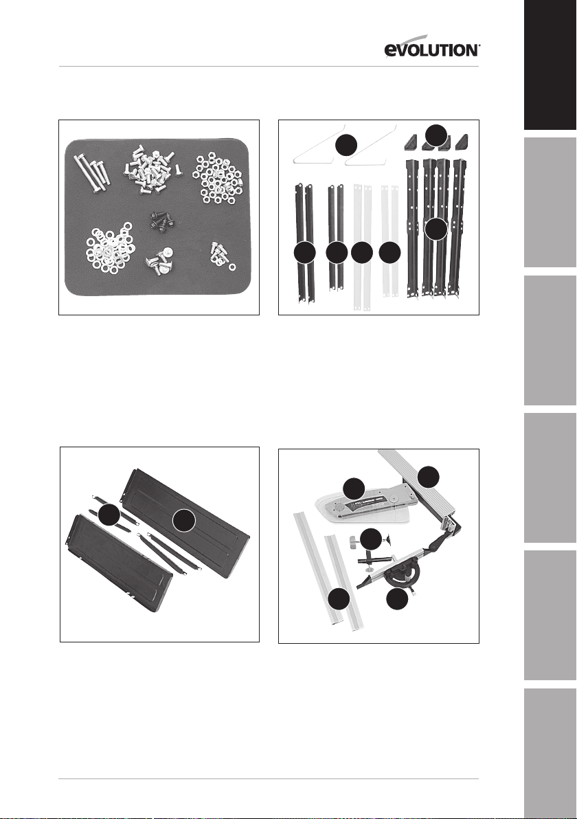
MACHINE OVERVIEW
EN
1. FIXINGS GROUPED IN SETS
B
A
G
C D E F
2.THE STAND COMPONENTS
A: 4 X BLACK CORNER LEGS
B: 4 X RUBBER FEET
C: 2 X BLACK TOP CROSSPIECES LONG
D: 2 X BLACK TOP CROSSPIECES SHORT
E: 2 X GREEN CROSSPIECES LONG
F: 2 X GREEN CROSSPIECES SHORT
G: 2 X REAR CANTILEVER BRACES
A
B
B
A
C
DE
FR
JP
3. TABLE EXTENSIONS AND STRUTS ETC
A: 2 X SIDE TABLE EXTENSIONS
B: 4 X SIDE TABLE SUPPORT STRUTS
DE
NL
4. OTHER PARTS
A: BLADE GUARD
B: ANTIBOUNCE DEVICE
C: RIP FENCE
D: MITRE GAUGE
E: FENCE RAIL 2 PIECE
TR
15
Page 16

Fig 1
Fig 2
www.evolutionpowertools.com
1. ASSEMBLY OF THE TABLE STAND
Note: This process can be considerably aided by studying the
images of an assembled machine as found on the original box
packaging.
Eight cross-pieces are supplied (See Fig 1). The black crosspieces are for the top of the stand, the green ones are for mid
way fixing. The cross-pieces are paired, with two long and two
short of each colour.
Identify all parts before proceeding with assembly.
1. Fit the flexible rubber feet to the four legs. The two
turned over metal tabs should be guided into the two
25mm slots in the base of the rubber foot which can
then be moulded around the base of the leg.
2. Select two legs, a long top cross-piece and a long green
cross-piece. Fit the top cross-piece to each leg using one
6mm hex bolt, ensuring that the locating lug on the cross-piece
engages into the rectangular slot in the top of the leg. Fit the
green cross-piece using four 6mm hex bolts. This cross-piece
has sloped ends to accommodate the splay of the legs. Ensure
it is fitted correctly with slope facing upwards. Do not fully
tighten any of the bolts at this stage. This assemblage will
become a side of the stand and should resemble a flat
topped letter ‘A’. See Fig 2.
Fig 3
Fig 4
3. Repeat the above to produce a second side.
4. Using the remaining two top cross-pieces and two green
cross-pieces, join the sides together to form the rectangular
base of the table stand.
Ensure that the mounting holes formed by the top cross-pieces
at each corner of the stand are in alignment. The machine
mounting bolts can be loosely fitted in place as an aid to
alignment. (Front ø6mm x 30mm, rear ø6mm x 55mm)
5. Fit the two cantilever braces to a narrow side. This will
become the rear of the stand. These will provide extra
stability and safety when the saw is in use See Fig 3.
When finally satisfied with the construction, tighten all nuts
and bolts securely, and remove the mounting bolts from the
corner holes. See Fig 4.
16
Page 17

www.evolutionpowertools.com
2. ATTACHING THE MAIN BODY TO THE STAND
WARNING: This machine is heavy, enlist competent
help when fastening this machine to its base.
The main body of the saw can now be attached to the stand
using the four bolts, washers and nuts provided. Ensure that the
saw is attached to the stand the correct way round. The bolts
fasten through the machines four corner mounting holes, and
through the four corner holes in the stand. See Fig 5.
3. TABLE EXTENSIONS
Note: The pressed steel table extensions are not handed
and can fit on either side of the machine. However the
single hole in the end of the extensions should be to
the front of the saw table.
1. Attach the four bracing struts to the table extensions using
6mm hex bolts with a washer under the head of the bolt as well
as the nut. Position the front strut in the first slot. Position the
rear strut in the single slot to the rear of the extension. Tighten
both struts in the middle of their respective slots. See Fig 6.
2. Captive nuts are incorporated into the RH and LH edges of
the table. Attach the table extensions (single hole to the front)
to the table top using the ø5mm socket headed screws and
washers.
EN
DE
Fig 5
FR
Fig 6
JP
3. Ensure that the saw table edge and extension table edge
are flush and level with each other. Tighten the ø5mm socket
screws. See Fig 7.
4. Using a straight edge or similar placed across the table and
extension to ensure alignment, position each bracing strut to its
body mounting turret. Use the hex headed self tapping screw
to secure each bracing strut to its turret. The screw will cut its
own thread into the turret slot. See Fig 8.
5. Final micro adjustment and alignment of the table
extensions is possible by repositioning the relevant fixing
screw in their slots.
17
Fig 7
NL
Fig 8
TR
Page 18
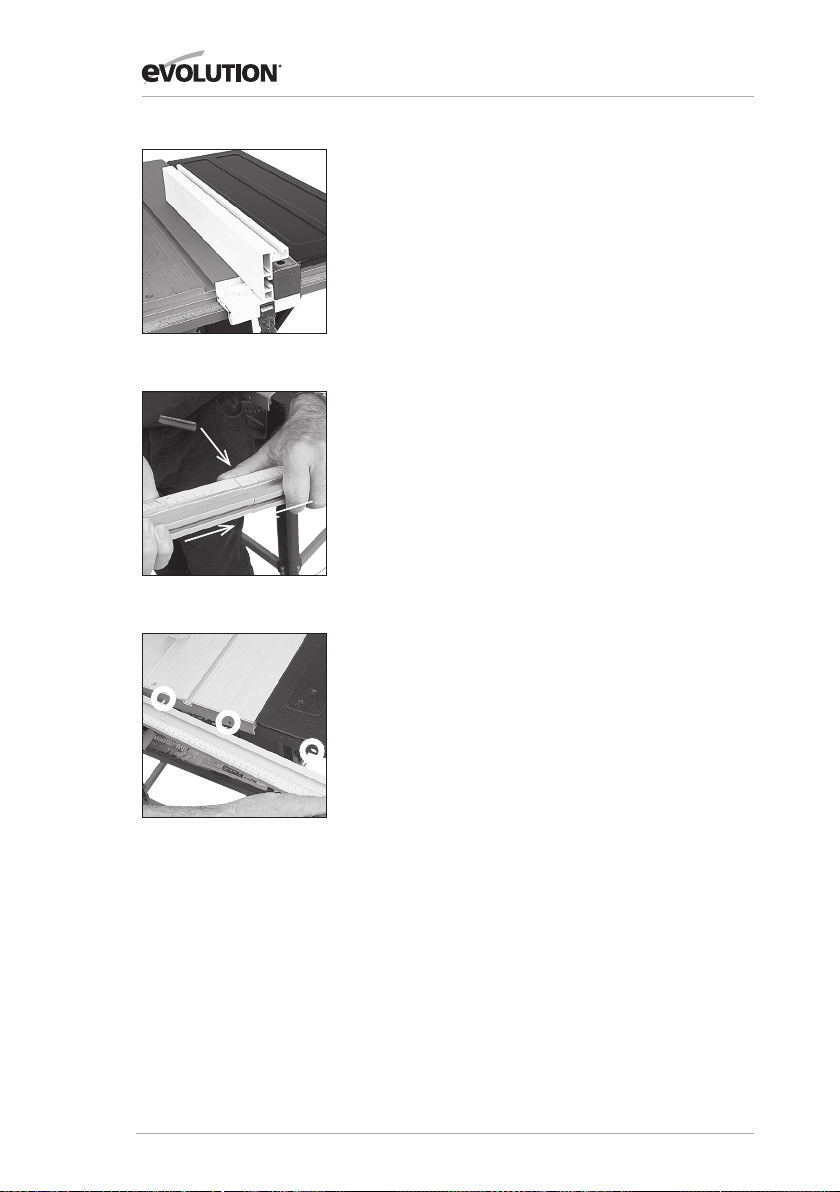
Fig 9
Fig 10
www.evolutionpowertools.com
4. ASSEMBLING THE RIP FENCE
The rip fence guide has an adjustable aluminium faceplate.
For normal use this should be attached to the steel carrier
of the rip fence with the deep (60mm) side in the vertical
position and on the LH side of the carrier. See Fig 9.
1. Place the two ø6mm x 60mm dome headed coach-bolts into
the two through holes in the carrier, dome heads to the LH side.
2. Put washers and the finger nuts (by only
a couple of threads) onto the RH side of the carrier.
3. Slide the aluminium faceplate onto the bolt heads.
4. Tighten the two finger nuts.
Note: The magnifier in the Rip Fence clamp should be visible.
5. THE FENCE RAIL
Note: The Fence Rail is supplied in two pieces which slot
together. The metal locating bar should be inserted into the
rectangular voids of the two extrusions to bridge both parts
of the fence rail. The bar should be equally located in either
side of the fence rail. See Fig 10. The six ø6mm x 15mm
domed headed coach bolts should be slid into the channel
at the back of the Fence Rail.
Fig 11
1. Offer the Fence Rail up to the front of the machine.
2. Position the six bolts to align with the six holes (one in each
extension and four in the main aluminium table). See Fig 11.
3. Attach the Fence Rail to the machine using
washers and ø6mm nuts. Hand tighten only.
ADJUSTING
WARNING: The machine must not be connected to its
mains supply when carrying out the following procedure.
The Fence Rail needs to be positioned correctly
for its scale to read accurately.
18
Page 19

www.evolutionpowertools.com
1. Locate the Rip Fence in the Fence
Rail to the RH side of the Blade.
2. Raise the saw blade (see Operation Controls 2)
3. Slide the Rip Fence along the Fence Rail
until it rests against the raised saw blade.
4. Look through the Rip Fence magnifier, and gently move the
Fence Rail to the right or left until the ‘0’ position on the scale
coincides with the datum line in the magnifier. See Fig 12.
5. Check, and when satisfied that calibration has been
achieved, tighten the six Fence Rail nuts securely.
6. Lower the Blade.
Note: The Rip Fence simply slots into the Fence Rail, and can
be locked into position anywhere along the rails length, and at
either side of the machine by pressing the locking lever down.
6. CHECKING/ADJUSTING THE RIP FENCE
When the Fence Rail and Rip Fence have been attached
to the machine, the Rip Fence should be checked to
ensure that it lies parallel to the blade.
EN
DE
Fig 12
FR
1. Raise the blade to its full height.
2. Rest a straight-edge or similar against the blade.
3. Bring the Rip Fence up to the
straight-edge and check for parallelism.
4. If adjustment is needed, gain access to the two socket headed
screws through the two holes in the steel carrier. See Fig 13.
5. Loosen these screws using the correct sized
allen key, and adjust the fence as required.
6. Tighten and re-check the Rip Fence when
correct alignment has been achieved.
7. Lower the blade.
7. SLIDING MITRE GAUGE
Note: The sliding mitre gauge fits in either
of the inverted ‘T’ slots in the machine table.
The adjustable aluminium faceplate is held in the plastic
protractor base of the mitre gauge by two ø6mm domed
headed screws and thumb nuts. The anti-bounce device can be
fitted into the socket incorporated into the mitre gauge base.
See Fig 14. Turning the locking handle anti-clockwise allows
the mitre gauge angle to be adjusted. Use the protractor scale
and pointer and set the gauge to the desired angle. Tighten the
vertical handle when the required angle has been set.
19
Fig 13
JP
Fig 14
NL
TR
Page 20

Fig 15
Fig 16
Fig 17A
www.evolutionpowertools.com
Note: It is recommended that the anti-bounce device is fitted
only when needed (e.g. when cutting thin sheet material or
thin walled metal tube etc). At other times store away off the
machine for future use.
The pillar of the anti-bounce device fits into the socket
in the mitre gauge base, and is held in place by a set screw.
See Fig 15. To attach or remove the pillar the mitre gauge
faceplate will have to be removed to gain access
to the set screw.
8. TOP BLADE GUARD
The top blade guard must be fitted to the machines riving knife.
The ‘split’ line along the top of the guard indicates the cutting
line of the saw blade below. Graphics on the guard further
reinforce the cutting line of the saw blade.
WARNING: The machine must be disconnected from
the mains supply when installing the blade guard.
1. Raise the blade to its full height to fully reveal the riving knife.
2. The guards locating pin should be positioned through the
hole in the riving knife and the washer and wing nut fitted to
one side. The blade guard must move up and down easily and
smoothly, so do not over-tighten this wing nut. See Fig 16.
3. Check the operation of the blade guard. Ensure that it is
working efficiently and covers the blade entirely at the sides as
well as the crown.
4. Lower the blade a little and recheck that the blade guard
operation.
5. When satisfied that the blade guard works throughout the
blades height adjustment range, check that when the blade is
fully lowered, the blade guard and side covers are in contact
with the table top. See Fig 17A.
Note: Guard Setting for Bevel, Mitre & Compound Cuts
When bevel, mitre or compound cutting it may be necessary
to remove the left or both blade side covers. See Fig 17B.
Fig 17B
Use a crosshead screwdriver to remove the side cover
attachment screws and their plate washers. Securely store
the side covers, screws and washers for future use.
20
Page 21

www.evolutionpowertools.com
The guard should be secured to the riving knife by tightening
the locating pin wingnut. The guard should be positioned
so that the workpiece just slides under it, with the maximum
number of teeth possible shielded by the guard. Return the
guard to the original configuration when bevel, mitre or
compound cutting is completed. Recheck the operation
of the blade guard.
OPERATION
EN
DE
Controls
1. On/Off Safety Switch
WARNING: Before turning on the switch make sure that the
blade guard is correctly installed and operating properly.
To start the machine, press the tabs on either side of the red
safety button and lift it and the switch cover plate upwards to
reveal the on and off buttons. Push the ‘ON’ button to start the
machine and the ‘OFF’ button to stop the machine. See Fig 18.
WARNING: Never start the machine until all safety
checks and procedures have been carried out.
2. Raising/Lowering the blade
WARNING: Only make adjustments to the machine when the
machine is switched OFF and the blade is stationary.
The raising and lowering handle is used to raise or lower the
blade. Turn clockwise to lower the blade and counter-clockwise
to raise the blade. See Fig 19.
3. Tilting the Blade
The blade can be tilted up to 45
0
to the left. To tilt the blade
loosen the tilt locking lever and turn the tilt adjusting wheel
until the desired angle is achieved. Tighten the tilt locking lever
before using the machine. See Fig 20 (A) and Fig 20 (B).
Fig 18
FR
Fig 19
JP
Fig 20A
NL
4. Rip Fence Guide
The rip fence can be positioned either side of the blade and is
locked in position by using the locking lever. Push down to lock,
and pull up to unlock.
Note: The rip fence guide incorporates a magnifier to aid
reading the measurement scale found on the fence rail.
21
Fig 20B
TR
Page 22

Fig 21
Fig 22
www.evolutionpowertools.com
Forwards and backwards adjustment of the rip fence is possible.
Loosen the two finger nuts and slide the aluminium extrusion
to the desired position. Tighten the finger nuts securely.
Note: We recommend that normally the rip fence be adjusted
so that the rear of the guide is level with the rear of the blade
where it emerges from the table. See Fig 21.
Note: If the rip fence is used on the LH side of the blade
the aluminium extrusion will have to be repositioned to
the RH side of the steel box-section carrier.
Undo the two wing nuts and remove the aluminium extrusion
with its bolts in place. Reposition the extrusion on the RH side
of the steel carrier and re-attach the wing nuts. See Fig 22.
Adjust as above.
Remember to return to the original configuration when the rip
fence is in the normal (RH) operating position.
5. Mitre Gauge
The mitre gauge can be used on either side of the table and
runs in two inverted T slots in the table top.
Turn the vertical handle counter-clockwise to unlock
the mitre gauge, and adjust to the required angle.
Turn the handle clockwise to lock the mitre gauge
at the chosen angle. See Fig 23.
Fig 23
Fig 24
Note: The extruded aluminium face plate of the mitre
gauge should be adjusted so that it is close to, but does not
foul the blade guard. Adjust by loosening the two wing nuts
and sliding the faceplate to the required position. Securely
tighten the wing nuts.
6. ANTIBOUNCE DEVICE
If required, when cutting thin sheet or thin walled box-section
material (maximum 3mm thickness applies when Steel cutting),
the anti-bounce device can be employed. See Fig 24. Adjust
using the adjustable handle and knob for best position.
Note: Adjust the anti-bounce device so that the head does
not quite touch the material to be cut. You can achieve this by
gently clamping the material to be cut with the anti-bounce
device, and then backing off the head by 1/4 to1/2 a turn.
22
Page 23

www.evolutionpowertools.com
BASIC TABLE SAW OPERATIONS
WARNING: Never attempt freehand cuts on this machine.
Always use the appropriate guide or fence to minimise the
possibility of the blade binding and kickback. We recommend
that the saw blade protrudes through the material to be cut
by approximately 3mm. Adjust the height of the blade as
previously described. This machine is not suitable for cutting
rebates or stopped grooves. A vacuum cleaner or workshop
dust extraction device can be connected to the extraction port
found at the rear of the machine if required. See Fig 25.
Note: Adjust the blade guard for mitre, bevel
or compound cutting as detailed in Assembly 8.
EN
DE
Fig 25
1. Crosscutting
Set the mitre gauge to 0
0
and tighten using the vertical handle.
Position in the desired ‘T’ slot and adjust the mitre face plate as
previously described. Index the material to be cut against the
mitre gauge faceplate. Switch on the saw and allow to reach
full operating speed before making your cut. See Fig 26.
Note: Adjust the blade guard for mitre, bevel or compound
cutting as detailed in Assembly 8.
2. Mitre crosscutting
Mitre crosscutting is cutting the material at an angle other
0
than 90
. Set the mitre gauge to the desired angle, tighten
and proceed as crosscutting above.
3. Bevel crosscutting
Bevel crosscutting is the same as crosscutting but with the
blade tilted at an angle. Tilt the blade to the desired angle as
previously described, and ensure that it is locked in place. Set
the mitre gauge to 0
0
and adjust the faceplate so that it does
not touch or foul the saw blade as it passes. Index the material
against the mitre gauge and make your cut. See Fig 27.
4. Compound mitre cutting
Compound mitre cutting is a combination of mitre cutting and
bevel crosscutting. Adjust the mitre gauge and the blade to the
desired angles. Lock both in place. Check that the mitre gauge
will pass the saw blade without fouling. Adjust the mitre gauge
faceplate if necessary. See Fig 28. Index the material against
the mitre gauge and make your cut.
FR
Fig 26
JP
Fig 27
NL
23
Fig 28
TR
Page 24

www.evolutionpowertools.com
5. Repetitive crosscutting
Repetitive cutting is cutting a number of pieces to the same
length without having to mark out each piece.
Note: We recommend that repetitive cross-cutting is carried
out with the mitre gauge positioned on the LH side of the
machine, with the rip fence on the RH side of the machine.
See Fig 29. The rip fence can be used as a length stop
if it is properly set and adjusted.
Fig 29
Fig 30
Fig 31
Note: Align the back of the fence with the front of the saw
blade. This will allow clearance for the material as it passes
through the saw blade.
Index the material to be cut against the mitre gauge and the rip
fence. Hold the material and mitre gauge with your left hand.
Gently push the workpiece through the saw. Use a push stick,
if necessary, in your right hand to guide the workpiece on the
RH side of the blade.
6. Rip cutting
Rip cutting is cutting along the length of a piece of material
rather than across it. See Fig 30. Rip cutting should always be
done with the rip fence set to the desired width and normally
on the RH side of the machines table. The mitre gauge is not
required for this operation, and should be stored safely off the
machine for future use.
Note: Check that the rip fence is locked in position and is
parallel to the saw blade. Check that the riving knife is properly
aligned with the saw blade.
When ripping small section material a push stick should be
used to feed/guide the final 300mm of the material past the
blade. A push stick should always be used when making cuts
of less than 300mm. See Fig 31.
When ripping long boards or large panels always use a work
support. Feed the workpiece through the saw keeping it
indexed against the rip fence. Use smooth, steady pressure
and employ a push stick if necessary.
24
Page 25

www.evolutionpowertools.com
When the ripping width is greater than 300mm, and with care,
both hands can be used to guide/feed the material through the
saw. The operators left hand will be to the LH side of the saw
blade. The operators right hand will be close to the rip fence on
the RH side of the saw blade. Hands should never be in line with
the blade.
EN
7. Bevel ripping
When bevel ripping material 150mm or narrower use the rip
fence on the RH side of the blade only. See Fig 32.
MAINTENANCE
WARNING: Ensure that the machine is disconnected
from the mains supply before any maintenance tasks
or adjustments are attempted.
Changing the Blade
Note: We recommend that the operator considers
wearing protective gloves when handling or changing
the machines blade.
1. Disconnect the machine from the power supply.
2. Remove the blade guard. (see Assembly 7).
3. Remove the table access plate by removing the two
countersunk head screws from either end of the access plate.
Lift the plate away and carefully store it and its fixing screws for
future use. See Fig 33.
4. Raise the blade to its highest position.
5. Use the two blade changing tools provided. One to hold the
motor arbor, and the other to loosen the arbor nut. See Fig 34.
6. Remove the nut, outer flange and blade.
7. Fit the new blade. Ensure that the teeth are facing to the front
of the saw, and that the arrow on the blade is in line with the
motor direction.
8. Replace the outer flange and nut and tighten securely with
the spanners provided. Check that both blade flanges are in
contact with the blade.
9. Replace the table access plate and its fixing screws. Ensure
that the fixing screws are correctly seated.
10. Replace the blade guard.
DE
Fig 32
FR
Fig 33
JP
Fig 34
NL
25
TR
Page 26

www.evolutionpowertools.com
Cleaning
After each use the machine should be cleaned. Remove
all sawdust etc from the visible parts of the machine with
a vacuum cleaner. A vacuum cleaner can also be connected
to the machine dust extraction port at the rear of the machine.
This should remove debris from the inside of the machine.
Never use solvents to clean plastic parts, as solvents can
damage them. Clean only with a soft damp cloth.
Fig 35
Fig 36
Riving Knife
The riving knife is a very important component and comes
factory fitted and correctly aligned and adjusted. The riving
knife prevents the work from binding as it passes through the
blade. Inspect the riving knife at regular intervals and replace
it if it is worn or damaged.
Note: Use only a genuine Evolution Riving Knife, as this
is a dedicated component for this machine. Non genuine
parts could be dangerous. If in any doubt, please contact
the Helpline.
Push Stick
A plastic push stick is provided with the machine and has its
own dedicated storage brackets to the RH side of the machines
main body. See Fig 35. When not in use store the push stick
on the machine.
Note: If the push stick becomes damaged it should be replaced.
If the operator makes their own push stick, we recommend that
it follows the same pattern as that supplied. Replacement push
sticks are available from Evolution Power Tools.
Blade Storage
A blade storage facility is available at the rear of the machine.
See Fig 36. Undo the centre hand nut and place any spare
blades onto the ø25.4mm metal flange. Secure the blades
with the centre hand nut.
(6.4) ENVIRONMENTAL PROTECTION
Waste electrical products should not be disposed of with
household waste. Please recycle where facilities exist. Check
with your Local Authority or retailer for recycling advice
26
Page 27

www.evolutionpowertools.com
PARTS DIAGRAM
EN
DE
FR
27
JP
NL
TR
Page 28

www.evolutionpowertools.com
EC DECLARATION OF CONFORMITY
In accordance with EN ISO 17050-1:2004
The manufacturer of the product covered by this Declaration is:
Evolution Power Tools, Venture One, Longacre Close, Holbrook Industrial Estate, Sheffield, S20 3FR.
The manufacturer hereby declares that the machine as detailed in this declaration fulfils all the
relevant provisions of the Machinery Directive and other appropriate directives as detailed below.
The manufacture further declares that the machine as detailed in this declaration, where
applicable, fulfils the relevant provisions of the Essential Health and Safety requirements.
The Directives covered by this Declaration are as detailed below:
2006/42/EC. Machinery Directive.
2004/108/EC. Electromagnetic Compatibility Directive.
93/68/EC. The CE Marking Directive.
2011/65/EU. The Restriction of the Use of certain Hazardous
Substances in Electrical Equipment (RoHS) Directive.
2002/96/EC as The Waste Electrical and Electronic Equipment (WEEE) Directive.
amended by
2003/108/EC .
And is in conformity with the applicable requirements of the following documents:
EN61029-1:2009 • EN61029-2-1:2010 • EN55014-1:2006
EN 55014-2:1997+A1 • EN61000-3-2:2006 • EN61000-3-3:1995+A1+A2
Product Details
Description: FURY5 255mm (10”) MULTIPURPOSE TABLE SAW
Evolution Model No: FURY52552 / FURY52552EU
Brand Name: EVOLUTION
Voltage: 230V
Input: 50Hz
The technical documentation required to demonstrate that the product meets the requirements
of directive has been compiled and is available for inspection by the relevant enforcement
authorities, and verifies that our technical file contains the documents listed above
and that they are the correct standards for the product as detailed above.
Name and address of technical documentation holder.
Signed: Print: Steven Bulloss: Operations Director.
Signed: Print: Lettie Lui: Product Manager.
Date: 01/06/2010
28
Page 29

www.evolutionpowertools.com
NOTES
EN
DE
FR
29
JP
NL
TR
Page 30

UK
Evolution Power Tools Ltd
Venture One
Longacre Close
Holbrook Industrial Estate
Sheffield
S20 3FR
US
Evolution Power Tools LLC
8363 Research Drive
Davenport
Iowa
52806
+44 (0)114 251 1022
JP
エ ボ リュ ー シ ョン
パワーツール株式会社
〒544-0031
大阪府大阪市生野区
鶴 橋 5 丁 目 21-19
0120-051-415
866-EVO-TOOL
EU
Evolution Power Tools Ltd
61 Avenue Lafontaine
33560
Carbon-Blanc
Bordeaux
+ 33 (0)5 57 30 61 89
Discover Evolution Power Tools
Visit: www.evolutionpowertools.com or download
the QR Reader App on your smart phone and scan
the QR code (Right).
 Loading...