

Page 1

255 mm TCT Multi Purpose Sliding Compound Mitre Saw
Original
Instructions
Read instructions before operating this tool.
www.evolutionfury.com
®
21.10.10_V2
Page 2

2
www.evolutionfury.com
TABLE OF CONTENTS
EC - Declaration of Conformity 02
Important Information 03
12 Month Limited Warranty 03
General Safety Rules 03
Safety Instructions for all Saws 05
Additional Specific Safety Rules 06
Symbols and Labels 08
Specification 08
Machine Overview 10
Assembly 11
Operation 13
Maintenance 18
Environmental Protection 18
Service Parts Lists 19
EC - DECLARATION OF CONFORMITY
We, manufacturer and importer
Evolution Power Tools Ltd.
Venture One
Sheffield
S20 3FR
Declare that the product
Part numbers:
Part numbers: FURY32552, FURY32552EU
Evolution: FURY 3 XL Multi Purpose Sliding
Compound Mitre Saw
Complies with the essential requirements
of the following European Directives:
2006/42/EC – Machine Directive
2006/95/EC – Low Voltage Directive
2004/108/EC – EMC Directive
2002/95/EC – Restriction of the use of
Certain Hazardous Substances in Electrical
and Electric equipment.
The following standards have been applied:
EN 61029-1:2009
EN 61029-2-9:2002
EN 55014-1:2006+A1:2009
EN 55014-2:1997+A1:2001+A2:2008
EN 61000-3-2:2006+A1:2009+A2:2009
EN 61000-3-3:2008
EN 60825-1:2007
Authorised by
Mr Matthew J Gavins
Managing Director
1st June 2010
®
EC - DECLARATION OF CONFORMITY
GB
Page 3

3
www.evolutionfury.com
All documentation is held on file at
the above address and is available, on
request for review.
IMPORTANT
Please read these operating and safety
instructions carefully and completely. For your
own safety, before using this equipment check
that the voltage is correct and that all handles
and parts are firmly secured. If you are uncertain
about any aspect of using this equipment,
please contact our Technical Helpline.
Helpline.
Technical Helpline UK 0870 609 2297
Technical Helpline USA 1-866-EVO-TOOL
EVOLUTION 255mm FURY 3XL
Multipurpose Sliding Compound Mitre Saw
Congratulations on your purchase of an
Evolution Power Tool’s 255mm Multi Purpose
Compound Mitre Saw. Please complete your
product registration on line to validate your
machine’s warranty period and ensure prompt
service if needed. We sincerely thank you for
selecting a product from Evolution Power Tools.
12 MONTH LIMITED WARRANTY
Evolution Power Tools reserves the right to
make improvements and modifications to
design without prior notice.
Evolution Power Tools will, within twelve (12)
months from the original date of purchase,
repair or replace any goods found to be
defective in materials or workmanship. This
warranty is void if the tool being returned
has been used to cut materials beyond
the recommendations in the Instruction
Manual or if the saw has been damaged by
accident, neglect, or improper service. This
warranty does not apply to machines and
/ or components which have been altered,
changed, or modified in any way, or subjected
to use beyond recommended capacities
and specifications. Electrical components
are subject to respective manufacturers’
warranties. All goods returned defective shall
be returned prepaid freight to Evolution Power
Tools. Evolution Power Tools reserves the
right to optionally repair or replace it with the
same or equivalent item. There is no warranty
– written or verbal – for saw blades. In no
event shall Evolution Power Tools be liable for
loss or damage resulting directly or indirectly
from the use of our merchandise or from any
other cause. Evolution Power Tools is not
liable for any costs incurred on such goods or
consequential damages. No officer, employee
or agent of Evolution Power Tools is authorised
to make oral representations of fitness or to
waive any of the foregoing terms of sale and
none shall be binding on Evolution Power Tools.
Questions relating to this limited warranty
should be directed to the company’s head
office, or call the appropriate Helpline number.
IMPORTANT SAFETY INSTRUCTIONS
To reduce the risk of electric shock, this
equipment is fitted with an approved cord
and plug for its intended country of use.
Do not change the cord or plug in any way.
GENERAL SAFETY RULES
WARNING!
When using electric tools, basic safety
precautions should always be followed to
reduce the risk of fire, electric shock and
personal injury.
Please read all of these instructions before
attempting to operate this machine. Save
this manual for future reference.
1. Keep work area clear. Cluttered work
areas invite accidents.
2. Consider work area environment. Do
not expose tools to rain. Do not use tools
in damp or wet locations. Keep work area
well lit. Never use tools near flammable
liquids or gases.
3. Protect yourself against electric shock.
Avoid body contact with earthed or
grounded surfaces.
4. Keep other people away. Do not let others,
especially children, come close to the work,
and touch the tool or the extension lead.
Keep them away from the work area.
IMPORTANT INFORMATION
GB
12 MONTH LIMITED WARRANTY
GB
GENERAL SAFETY RULES
GB
Page 4

4
www.evolutionfury.com
5. Store idle tools. When not in use, tools
should be stored in a dry locked-up place,
out of children’s reach.
6. Never force the tools. Your tools will be
more efficient and safer when used at the
rate for which they were intended.
7. Use the right tool. Do not force small
tools to do the job of a heavy duty
tool. Do not use tools for purposes not
intended; for example do not use circular
saws to cut tree limbs or logs.
8. Dress properly. Do not wear loose
clothing or jewellery which may get
caught in moving parts. Non-skid
footwear is recommended when working
outdoors. If you have long hair, tie it back
and wear protective hair covering.
9. Use protective equipment. Use safety
glasses. Use face or dust mask if cutting
operations create dust.
10. Connect dust extraction equipment.
If the machines have a connection for
dust extraction equipment, ensure these
are connected and properly used.
11. Do not damage the cable. Never
pull the power cable to disconnect the
machine. Keep the cable away from heat,
oil and sharp edges.
12. Secure workpiece. Where possible,
use clamps or a vice to hold the workpiece.
It’s much safer than using your hands.
13. Don’t over reach. Keep proper footing
and balance at all times.
14. Maintain tools in good working
condition. Keep cutting tools sharp and
clean for better performance and optimum
safety. Follow instructions for lubricating
and changing accessories. Inspect power
cables regularly and, if damaged, have
them replaced by an authorised service
centre. Inspect extension cables regularly
and replace immediately if damaged. Keep
handles dry, clean and free from oil and
grease at all times.
15. Disconnect tools. Disconnect tools
from the power supply when not in use,
before any maintenance operation and
when changing accessories such as
blades, bits, cutters, etc.
16. Remove adjusting keys and spanners.
Get into the habit of checking that adjusting
keys and spanners have been removed
from the machine before turning it on.
17. Avoid unintentional starting. Ensure
switch is in “off” position before plugging
in the machine.
18. Use proper extension leads. When the
tool is used outdoors, use only extension
leads intended for outdoor use and
labelled as such.
19. Stay alert. Concentrate on what you
are doing, use common sense and do not
operate the tool when you are tired.
20. Check that no part is damaged. Before
using a tool, make sure that it is in good
working order. Check the alignment and
condition of moving parts, mounting
and any other aspect that may affect its
operation. A guard or other part that is
damaged should be properly repaired
or replaced by an authorised service
centre unless otherwise indicated in this
instruction manual. Do not use the tool
if the switch does not turn on and off.
21. Warning. The use of any accessory or
attachment other than one recommended
in this instruction manual may present a
risk of personal injury.
22. Have your tool repaired at an authorised
service centre. This electric tool complies
with current safety rules. Repairs should
only be carried out by an authorised service
centre using original spare parts. Failing
this, the user could expose themselves to
considerable danger.
®
Page 5

5
www.evolutionfury.com
HEALTH ADVICE
Warning!
When drilling, sanding, sawing or grinding,
dust particles will be produced. In some
instances, depending on the materials you
are working with, this dust can be particularly
harmful to you (e.g. lead from old gloss
paint).You are advised to consider the risks
associated with the materials you are working
with and to reduce the risk of exposure.
You should:
-Work in a well-ventilated area.
-Work with approved safety equipment,
such as dust masks that are specially
designed to filter microscopic particles.
SAFETY INSTRUCTIONS FOR ALL SAWS
a) DANGER: Keep hands away from
cutting area and the blade. Keep your
second hand on the auxiliary handle, or
motor housing. If both hands are holding
the saw, they cannot be cut by the blade.
b) Do not reach underneath the
workpiece. The guard cannot protect you
from the blade below the workpiece.
c) Adjust the cutting depth to the
thickness of the workpiece. Less than a
full tooth of the blade teeth should be visible
below the workpiece.
d) Never hold piece being cut in your hands
or across your leg. Secure the workpiece to
a stable platform. It is important to support
the work properly to minimize body exposure,
blade binding, or loss of control.
e) Hold power tool by insulated gripping
surfaces when performing an operation
where the cutting tool may contact
hidden wiring or its own cord. Contact
with a “live” wire will also make exposed
metal parts of the power tool “live” and
shock the operator.
f) When ripping always use a rip fence
or straight edge guide. This improves the
accuracy of cut and reduces the chance of
blade binding.
g) Always use blades with correct size
and shape (diamond versus round) of
arbor holes. Blades that do not match the
mounting hardware of the saw will run
eccentrically, causing loss of control.
h) Never use damaged or incorrect blade
washers or bolt. The blade washers and
bolt were specially designed for your saw, for
optimum performance and safety of operation.
Further safety instructions for all saws
Causes and operator prevention of kickback:
Kickback is a sudden reaction to a pinched,
bound or misaligned saw blade, causing an
uncontrolled saw to lift up and out of the
workpiece toward the operator:
1. When the blade is pinched or bound
tightly by the kerf closing down, the blade
stalls and the motor reaction drives the unit
rapidly back toward the operator;
2. If the blade becomes twisted or misaligned
in the cut, the teeth at the back edge of the
blade can dig into the top surface of the
workpiece causing the blade to climb out of
the kerf and jump back towards the operator.
Kickback is the result of saw misuse and/
or incorrect operating procedures or
conditions and can be avoided by taking
proper precautions as given below.
a) Maintain a firm grip with both hands
on the saw and position your arms to
resist kickback forces. Position your body
to either side of the blade, but not in line
with the blade. Kickback could cause the
saw to jump backwards, but kickback forces
can be controlled by the operator, if proper
precautions are taken.
b) If the blades are binding, or when
interrupting a cut for any reason, release
the trigger and hold the saw motionless
in the material until the blades come to a
complete stop. Never attempt to remove
the saw from the work or pull the saw
backward while the blades are in motion
or kickback may occur. Investigate and take
corrective actions to eliminate the cause of
blade binding.
SAFETY INSTRUCTIONS FOR ALL SAWS
GB
Page 6

6
www.evolutionfury.com
c) When restarting a saw in the
workpiece, centre the saw blade in the
kerf and check that saw teeth are not
engaged into the material. If saw blade is
binding, it may walk up or kickback from the
workpiece as the saw is restarted.
d) Support large panels to minimise
the risk of blade pinching and kickback.
Large panels tend to sag under their own
weight. Supports must be placed under the
panel on both sides, near the line of cut and
near the edge of the panel.
e) Blade depth and bevel adjusting locking
levers must be tight and secure before
making a cut. If blade adjustment shifts while
cutting. it may cause binding and kickback.
f) Do not use dull or damaged blades.
Unsharpened or improperly set blades
produce a narrow kerf causing excessive
friction, blade binding and kickback.
g) Use extra caution when making a
“plunge cut” into existing walls or other
blind areas. The protruding blade may cut
objects that can cause kickback.
Safety instructions for saws
a) Check lower guard for proper closing
before each use. Do not operate the saw
if lower guard does not move freely and
close instantly. Never clamp or tie the
lower guard into the open position. If
saw is accidentally dropped, lower guard
may be bent. Raise the lower guard with the
retracting handle and make sure it moves
freely and does not touch the blade or any
other part, in all angles and depths of cut.
b) Check the operation of the lower guard
spring. If the guard and the spring are not
operating properly, they must be serviced
before use. Lower guard may operate
sluggishly due to damaged parts, gummy
deposits, or a build-up of debris.
c) Lower guard may be retracted
manually only for special cuts such as
“plunge cuts” and “compound cuts.”
Raise lower guard by retracting handle
and as soon as blade enters the material,
the lower guard must be released. For
all other sawing, the lower guard should
operate automatically.
d) Always observe that the lower guard
is covering the blade before placing saw
down on bench or floor. An unprotected,
coasting blade will cause the saw to walk
backwards, cutting whatever is in its path.
Be aware of the time it takes for the blade
to stop after switch is released.
ADDITIONAL SAFETY INSTRUCTIONS
Warning: Be sure to read and understand all
instructions. Failure to follow all instructions
listed below may result in electric shock, fire
and/or serious personal injury.
a) Keep guards in place and in working order.
b) Remove adjusting keys and wrenches.
Form the habit of checking to see that keys
and adjusting wrenches are removed from
tool before turning it on.
c) Keep work area clean. Cluttered areas
and benches invite accidents.
d) Do not use in a dangerous environment.
Do not use power tools in damp or wet
locations, or expose them to rain. Keep work
area well lit.
e) Keep children away. All visitors should
be kept a safe distance from work area.
f) Do not force the tool. It will do the job
better and safer if used at the rate for which
it was designed.
g) Use proper extension cord. Make sure
your extension cord is in good condition.
When using an extension cord, be sure to
use one heavy enough to carry the current
your product will draw. An undersized cord
will cause a drop in line voltage resulting in
loss of power and overheating.
h) Wear proper apparel. Do not wear
loose clothing, gloves, neckties, rings,
bracelets, or other jewellery which may get
caught in moving parts. Nonslip footwear
recommended. Wear protective hair
covering to contain long hair.
i) Always use safety glasses. Also use face
or dust mask if cutting operation is dusty.
Everyday eyeglasses only have impact
resistant lenses, they are NOT safety glasses.
®
ADDITIONAL SPECIFIC SAFETY RULES
GB
Page 7

7
www.evolutionfury.com
j) Secure work. Use clamps to hold work
when practical. It’s safer than using your
hand and it frees both hands to operate tool.
k) Do not overreach. Keep proper footing
and balance at all times.
l) Maintain tools with care. Keep tools
sharp and clean for best and safest
performance. Follow instructions for
lubricating and changing accessories. Do not
use High Speed Steel (HSS) saw blades, or
blades that are damaged or deformed.
m) Disconnect tools before servicing and
when changing accessories, such as blades.
n) Reduce the risk of unintentional
starting. Make sure switch is in off position
before plugging in.
o) Use recommended accessories.
Only use genuine Evolution accessories.
When fitted with the correct blade (Fury
3 Multi-purpose TCT Blade) this saw is
recommended to cut Mild Steel, Aluminium
and Wood.
p) Never stand on tool. Serious injury could
occur if the tool is tipped or if the cutting tool
is unintentionally contacted.
q) Check damaged parts. Before further
use of the tool, a guard or other part that
is damaged should be carefully checked to
determine that it will operate properly and
perform its intended function - check for
alignment of moving parts, binding of moving
parts, breakage of parts, mounting, and any
other conditions that may affect its operation.
A guard or other part that is damaged should
be properly repaired or replaced.
r). Keep hands out of path of saw blade.
s) Never reach around saw blade.
t) Turn off tool and wait for saw blade
to stop before moving workpiece or
changing settings.
u) Disconnect power before changing
blade, servicing or cleaning.
v) To reduce the risk of injury, return
carriage to the full rear position after
each crosscut operation.
CARRYING YOUR MITRE SAW
Safety Advice
1. Although compact, this saw is heavy. To
reduce the risk of back injury, get competent
help whenever you have to lift the saw.
2. To reduce the risk of back injury, hold the
tool close to your body when lifting. Bending
your knees so you can lift with your legs, not
your back. Lift by using the handhold areas
at each side of the bottom of the base.
3. Never carry the mitre saw by the power
cord or the trigger grip of the handle.
Carrying the tool by the power cord could
cause damage to the insulation or the wire
connections resulting in electric shock or fire.
4. Before moving the saw tighten the slide
lock knob to guard against sudden movement.
WARNING!
Do not use the blade guard as a ‘lifting point’.
The power cord must be removed from the
power supply before attempting to move
the machine.
• Lockdowntheheadusingthehead
locking pin.
• Movethecuttingheadtoitsoutermost
position and lock in place by tightening the
slide lock knob.
• Loosenthemitreanglelockknob.Pullup
the mitre angle lever and rotate the table
to either of its maximum settings.
• Lockthetableinpositionusingthe
locking knob.
• Usethetwocarryhandlecut-outs
machined into either end of the machine
base, to transport the machine.
Place the saw on a secure stationary
work surface and check the saw over
carefully. Check particularly the operation
of all the machines safety features before
commissioning or operating the machine.
Page 8

8
www.evolutionfury.com
SAFETY LABELS & SYMBOLS
WARNING!
Do not operate machine if warning and
/ or instruction labels are missing or
damaged. Contact Evolution Power Tools for
replacement labels.
Symbol Description
V Volts
A Amperes
Hz Hertz
Min
-1
Speed
~ Alternating Current
n0
No Load Speed
Double Insulated
Wear Safety
Goggles
Wear Ear Protection
Do Not Touch
Wear Dust Protection
Restriction
of Hazardous
Substances Directive
CE certification
Waste electrical and
electronic equipment
Only use genuine Evolution replacement
saw blades. Unauthorized blades may be
dangerous! Keep saw blades securely
fastened. Check the blade flanges for debris
before installing any new blade. Do not use
dull, broken or damaged blades. Check the
blade regularly for condition and wear. A
damaged or worn blade should be replaced
immediately. Beware of ejecting chips as
they may be HOT. Always make provision for
the safe handling of excess material. Keep
machine base and rotary table free from dirt
and other debris.
To obtain an additional copy of your manual,
please contact Evolution Power Tools at:
UK 0870 609 2297
USA 1-866-EVO-TOOL
WEB www.evolutionpowertools.com
ADDITIONAL SAFETY INSTRUCTIONS
FOR YOUR MITRE SAW
FURY 3 XL SPECIFICATION
Designed to cut:
Mild Steel Plate -
Max Thickness 3mm
Mild Steel Box Section -
Max Wall Thickness 3mm
Aluminium
Wood –
Max section 75mm x 300mm
Technical Data
Motor (230v ~ or 110v ~ 50/60 Hz) (Watts):
2000W (Soft Start)
RPM No Load (min
-1
):
2500
Recommended Maximum Duty Cycle
(Minutes):
30mins
Blade Dimensions
Diameter: (10”) 255mm
Number of Teeth: 24
Bore Diameter: (1”) 25.4mm
Thickness: 2mm
Maximum Cutting Capacity (Wood)
At 900 mitre x 900 bevel
300mm x 75mm
At 450 mitre x 900 bevel
210mm x 75mm
At 450 mitre x 450 bevel
210mm x 40mm
®
SYMBOLS AND LABELS
GB
SPECIFICATION
GB
Page 9

9
www.evolutionfury.com
Noise and Vibration Data
Sound pressure level: 88.1dB(A) K=3dB(A)
Sound power level: 99.8dB(A) K=3dB(A)
Vibration level: 1.059 m/s2 K =1.5dB(A)
The declared vibration total value has been
measured in accordance with a standard test
method and may be used for comparing one
tool with another.
The declared vibration total value may also be
used in a preliminary assessment of exposure.
WARNING: The vibration emission during
actual use of the power tool can differ from
the declared total value depending on the
ways in which the tool is used. The need
to identify safety measures and to protect
the operator are based on an estimation of
exposure in the actual conditions of use (taking
account of all parts of the operating cycle, such
as the times the tool is switched off, when it is
running idle, in addition to trigger time).
ADDITIONAL ACCESSORIES
In addition to the standard accessories
supplied with this machine, other accessories
are available to improve its performance,
these include the following items:
1. Clamping System – the design of this
machine allows for the use of a front clamp
which can be fitted either side of the blade
in the sockets incorporated into the machine
base.
2. Diamond Blade – Convert this machine to
a ‘Tile Cutter’. By replacing the standard TCT
Blade with the optional Diamond Blade, this
machine becomes a tile cutter – suitable for
most ceramic / porcelain tiles.
Additional accessories can be obtained by
contacting your local dealer (or Evolution
Power Tools).
ITEM QUANTITY
Instruction Manual 1
Allen Key 1
Top Clamp 1
Multipurpose Blade 1 FURY3-XL
Support Bars 2
End Stop 1
Page 10
10
www.evolutionfury.com
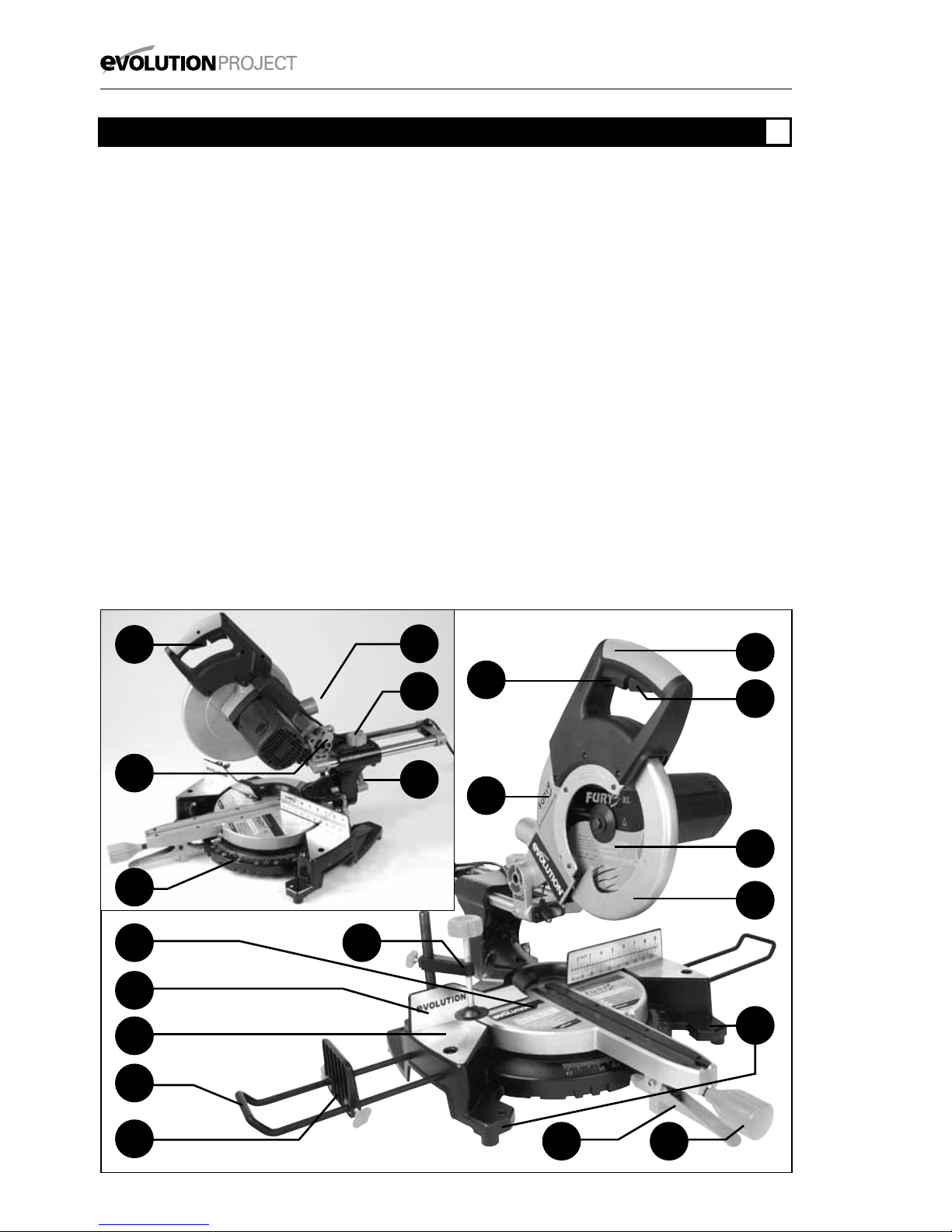
1. ON/OFF TRIGGER SWITCH
2. BLADE GUARD LOCKING TRIGGER
3. CUTTING HANDLE
4. DUST BAG EXTRACTION PORT
5. ROTARY TABLE
6. TABLE TOP
7. LOWER BLADE GUARD
8. UPPER BLADE GUARD
9. BLADE
10. SLIDE LOCKING KNOB
11. BEVEL LOCK LEVER
12. MITRE HANDLE
13. MITRE ANGLE SCALE
14. POSITIVE STOP LOCKING LEVER
15. WORKPIECE SUPPORT
16. REPEAT STOP
17. FENCE
18. TOP CLAMP
19. HEAD LATCHING PIN
20. MOUNTING HOLE
®
MACHINE OVERVIEW
GB
2
4
2
19
11
15
6
17
5
14
7
9
3
8
12
20
1
13
10
16
18
Page 11
11
www.evolutionfury.com
GETTING STARTED
CAUTION! ALWAYS DISCONNECT THE SAW FROM THE
POWER SOURCE BEFORE MAKING ANY ADJUSTMENTS.
Refer to the “Service Parts List Drawing”. Install a blade as
detailed in the “Installing or Removing the Blade” section.
1. Mounting the Mitre Saw
WARNING: To reduce the risk of injury from unexpected
saw movement, place the saw in the desired location either
on a workbench or other recommended leg set. The base
of the saw has four holes to mount the mitre saw. If the
saw is to be used in one location, permanently fasten it to
the workbench or leg set using appropriate bolts with lock
washers and nuts.
1. Tighten the slide, mitre and bevel locks.
2. Position the saw so other people cannot stand behind it.
Thrown debris could injure people in its path.
3. Place the saw on a firm, level surface where there is plenty
of room for handling and properly supporting the workpiece.
4. Support the saw so that the table is level and the saw
does not rock.
5. Bolt or clamp the saw to its support.
2. Installing or removing the blade
WARNING! Only use genuine Evolution blades which are
designed for this machine. Ensure that the maximum speed
of the blade is compatible with the machine. Only carry
out this operation with the machine disconnected from the
mains supply.
NOTE: It is recommended that the operator considers
wearing protective gloves when handling the blade during
installation or when changing the machines blade.
1. Ensure the cutting head is up.
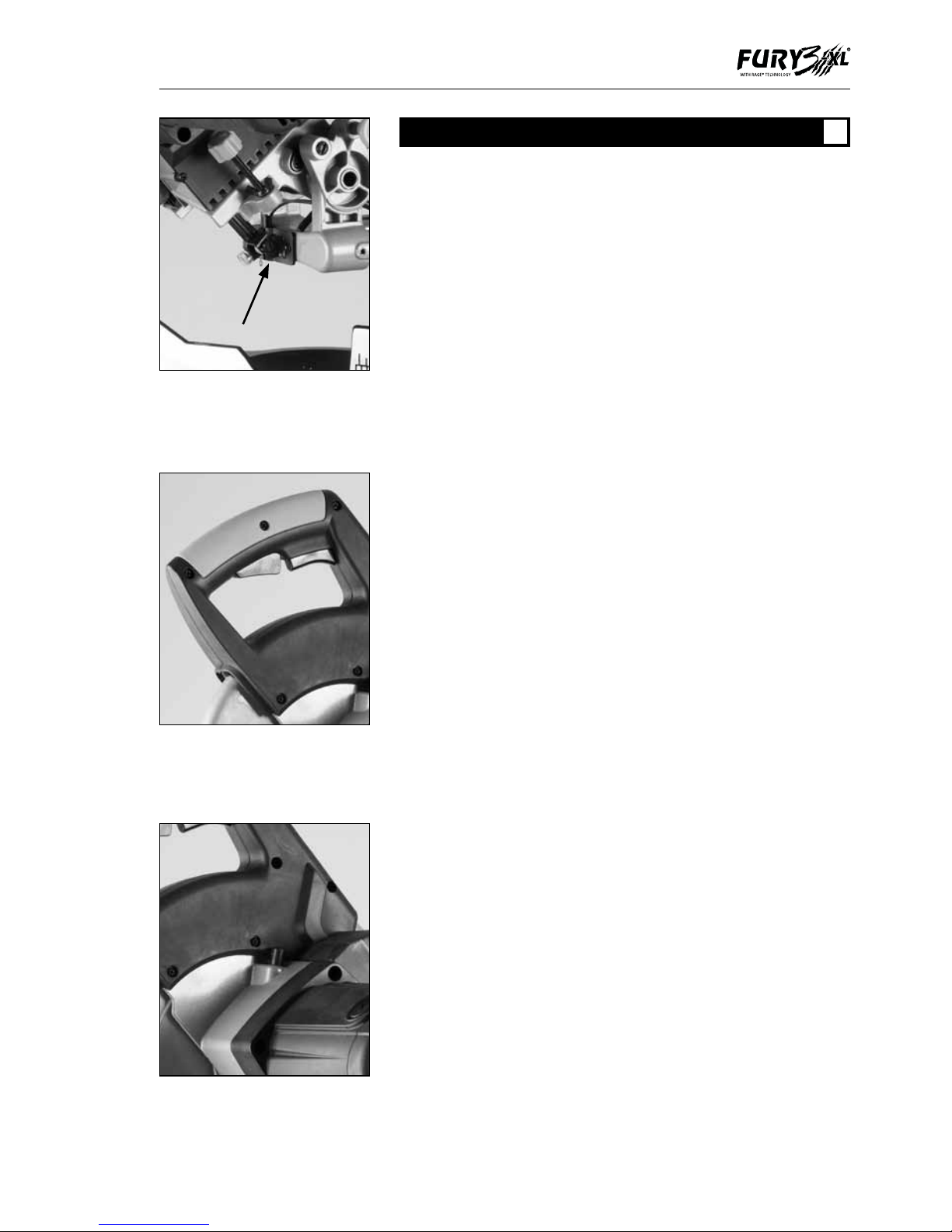
2. Remove the guard operating arm retaining clip (Fig. 1).
Release the guard operating arm from its pivot.
3. Press the lower blade guard locking trigger and lift up the
lower blade guard. (Fig. 2)
4. Press the black arbor lock button to lock the arbor. (Fig. 3)
5. Using the supplied Allen Key, release the arbor screw to
remove the blade. (Fig. 4)
Note: The arbor screw has a LH thread.
Fig 1
Fig 2
Fig 3
ASSEMBLY
GB
Page 12

12
www.evolutionfury.com
6. Install the new 255 mm (10”) blade. Make sure the
rotation arrow on the blade matches the clockwise rotation
arrow on the upper guard.
NOTE: The blade teeth should always point downward at the
front of the saw.
7. Install the blade washer and arbor screw.
8. Lock the arbor and tighten the arbor screw using moderate
force, but do not overtighten.
9. Replace the guard operating arm and its retaining clip.
(Fig. 1)
10. Ensure the Allen Key is removed and the arbor lock has
released before operating.
11. Ensure the blade guard is fully functional before using
the machine.
NOTE: Spacers and spindle rings should not be used with
this machine and/or blade.
3. Debris collection bag
The Debris Collection Bag should be attached at the debris
extraction port.
1. Slide the frame of the collection bag on to the outlet of the
extraction port, ensuring that it is firmly connected.
2. To release the bag, slide the frame in the opposite direction.
NOTE: To ensure optimal dust collection, empty the dust bag
when it becomes approximately 2/3 full.
WARNING: Before cutting metal materials, the collection
bag should be removed and replaced with a blanking plug.
Reinstate the dust bag when cutting wood.
4. Fitting the Repeat Stop
1. Loosen the repeat stop thumb screws sufficiently to allow
the arms of the workpiece support to slide through the holes
in the repeat stop.
2. Tighten the thumb screws firmly to minimize movement
on the workpiece support. Position the repeat stop
approximately half way along the workpiece support.
3. Attach the workpiece support to the machine base as
detailed below.
NOTE: By loosening the thumb screws the repeat stop can
be adjusted to the required distance from the saw blade
for repetitive cutting operations etc. The repeat stop should
normally be positioned to the RH side of the blade.
Fig 4
®
Page 13
13
www.evolutionfury.com
5. Fitting the Workpiece Support (Fig.5)
Workpiece supports can be fitted to both sides of the
machine base if required.
1. Right Hand side. Loosen the support retaining screw
located in the top front of the machines base.
2. Insert the workpiece supports into the retaining holes in
the base. Ensure positive location.
NOTE: Approximately 70mm of the Workpiece Support
should slide into the base to provide positive location.
3. Tighten the retaining screw.
4. Repeat above for the LH side.
6. Fitting the Upper Workpiece Clamp (Fig.6)
Two sockets (one either side) are incorporated into the rear
of the machines fence.
1. Fit the clamp to the retaining socket that best suits the
cutting application, ensuring that it is fully pushed down.
2. Tighten the fence thumbscrew to lock the pillar into the socket.
3. Put the workpiece to be cut onto the saw bed.
4. Adjust the clamp using the thumbscrew and hand-wheel
so that it securely holds the workpiece to the saw bed.
Ensure that the clamp does not foul the blade.
OPERATING INSTRUCTIONS
CAUTION: The Mitre Saw should be inspected (particularly
for the correct functioning of the safety guards) before each
use. Do not connect the saw to the power supply until a
safety inspection has been carried out.
Ensure that the operator is adequately trained in the use,
adjustment and maintenance of the machine, before
connecting to the power supply and operating the saw.
WARNING: To reduce the risk of injury, always unplug the
saw before changing or adjusting any of the machines parts.
Compare the direction of the rotation arrow on the guard
to the direction arrow on the blade. The blade teeth should
always point downward at the front of the saw. Check the
tightness of the arbor screw.
Laser Guide
This saw is equipped with a laser cutting guide. This allows
the operator to preview the path of the blade through the
workpiece. The ON/OFF switch for the Laser Guide is
positioned on the top of the motor housing. (Fig 7)
Avoid direct eye contact, and do not use on material that
could reflect the laser beam.
Fig 5
Fig 6
Fig 7
OPERATION
GB
Page 14

14
www.evolutionfury.com
WARNING: Do not stare directly at the laser beam. A hazard
may exist if you deliberately stare into the beam, please
observe all safety rules as follows.
• Thelaserbeamshallnotbedeliberatelyaimedat
personnel and shall be prevented from being directed
towards the eyes of a person.
• Alwaysensurethelaserbeamisonlyaimedatworkpieces
without reflective surfaces, i.e. wood or rough coated
surfaces are acceptable.
• Donotchangethelasermoduleassemblywithadifferent
type.
• Repairstothelasermodulemustonlybeconductedby
Evolution Power Tools or their authorized agent.
Body and Hand Position
1. Never place hands near the cutting area and keep hands
away from the path of blade.
2. Hold the workpiece firmly to the fence to prevent
movement toward the blade. Use a clamp if necessary but
check that it is positioned so that it does not foul the blade.
3. Before making a cut. Make a dry run with the power off so
you can see the path of the blade.
4. Keep hands in position until the ON/OFF trigger has been
released and the blade has completely stopped.
1. Releasing the saw head
a) Gently press down on the cutting handle.
b) Pull out the head latching pin and allow the head to rise to
its upper position.
NOTE: We recommend that when the machine is not in
use the cutting head is locked in its down position, and the
latching pin fully engaged in its socket.
2. Starting the Machine
Connect the machine to a mains power supply. Make sure
that the mains cable cannot become entangled in any part
of the machine and is clear of the blade and machine table.
Press the lower guard locking trigger and squeeze the On/Off
trigger switch to turn the saw ON. Release the trigger switch
to turn the saw OFF.
Always allow the motor to reach full speed before attempting
to make a cut.
3. Preparing to make a cut
Caution: NEVER pull the saw toward you during a cut. The
blade can suddenly climb up on top of the workpiece and
force itself toward you.
•Avoidawkwardoperations&handpositionswhereasudden
slip could cause fingers or hand to move into the blade.
®
Page 15

15
www.evolutionfury.com
•Cutonlyoneworkpieceatatime.
•Cleareverythingexcepttheworkpieceandrelatedsupport
devices away from the blade before turning the mitre saw on.
•Secureworkpieceusingclampstoholdtheworkpiece
securely.
4. Slide Cutting
This saw is equipped with a sliding carriage system.
Loosening the slide lock knob will release the slide and
allow the cutting head to move forwards and backwards.
The saw blade is lowered into the workpiece and then
pushed to the rear of the saw to complete the cut.
This type of cut can be used for cutting wide pieces.
1. Put workpiece against fence and secure with clamps as
appropriate.
2. Loosen the slide lock knob.
3. Grasp the saw handle and pull the cutting head until the arbor
(centre of saw blade) is over the front edge of the workpiece.
4. Press the lower blade guard locking trigger for cutting
head release.
5. Switch on the saw and allow the saw to reach full speed.
6. Push the saw handle all the way down and cut through the
leading edge of the workpiece.
7. Gently push the saw handle towards the fence completing
the cut.
8. Push the cutting head to the full rear position after each cut.
9. Release the trigger to switch off the saw. Allow the blade
to come to a complete halt before moving hands or removing
the workpiece.
5. Chop Cutting - The slide lock knob is tightened to lock
the cutting head at its rearmost position. The saw handle is
pushed down to cut through the workpiece. This type of cut
is used mainly for narrow pieces.
1. Slide the cutting head to the rear as far as it will go.
2. Tighten the slide lock knob.
3. Place the workpiece on the table and against the fence
and secure with clamps as appropriate.
4. Grasp the saw handle.
5. Turn on saw and allow the saw to reach full speed.
6. Press the lower guard locking trigger for saw head release.
7. Push the saw handle down and cut through the workpiece.
8. After the cut is completed turn off the saw and allow the
blade to come to a complete halt before moving hands or
removing the workpiece.
WARNING: For your convenient use, the saw has a blade
brake. Never rely on it to replace proper use of the guard
on your saw.
Page 16
16
www.evolutionfury.com
6. Mitre Cut (Fig. 8)
An angle of up to 450 to the left or right can be obtained.
Positive stops are provided at 150, 22.50, 300 and 450 right
and left.
1. Loosen the slide locking knob, and push the cutting head
back as far as it will go and lock the slide.
2. Loosen the mitre angle lock knob.
3. Pull up the positive stop locking lever.
4. Turn the rotary table to the desired angle as indicated by
the mitre angle pointer.
5. Tighten the mitre angle lock knob to hold the desired angle.
6. If necessary unlock the cutting head by loosening the
slide locking knob. This will allow the cutting head to move
backwards and forwards (required when cutting wide boards).
7. Start the saw and allow it to reach full speed before
commencing operations.
7. Bevel Cut Left (Fig. 9)
1. Lock the cutting head down with the head latching pin.
2. Loosen the bevel lock lever.
3. Tilt the cutting head to the required angle. A protractor
scale and pointer is provided to aid setting. This is found just
behind the bevel lock lever.
4. Tighten the bevel lock.
5. Unlatch the cutting head.
6. Release the slide (if necessary) to cut wide workpieces.
7. Stand to the left side of the handle to make the cut
8. Compound Cut
A compound cut is a combination of a mitre and bevel cut.
When a compound cut is required, select the desired bevel
and mitre positions as previously explained.
9. Depth Stop (Fig.10)
Use of the depth stop allows the operator to cut slots in the
workpiece. The downward travel of the saw head can be set
so that the saw blade does not completely cut through the
workpiece.
Note: It is advisable that the depth of cut is checked using a
scrap piece of timber to ensure that the slot cut is correct.
By making a cut in the workpiece, and then repeating the
cut but with the workpiece slightly repositioned to the left or
right, it is possible to perform trenching cuts.
To use the depth stop:
1. Loosen the locking wing nut.
2. Adjust the thumb knob to limit the saw heads travel to the
required depth.
3. Once set to the desired depth, tighten the wing nut
against the retaining bracket to lock the depth stop and
Fig 9
Fig 10
®
Fig 8
Page 17
17
www.evolutionfury.com
ensure that there is no movement.
4. When cutting is complete re-adjust the depth stop so that
the cutting head can be locked in the down position by the
head latching pin.
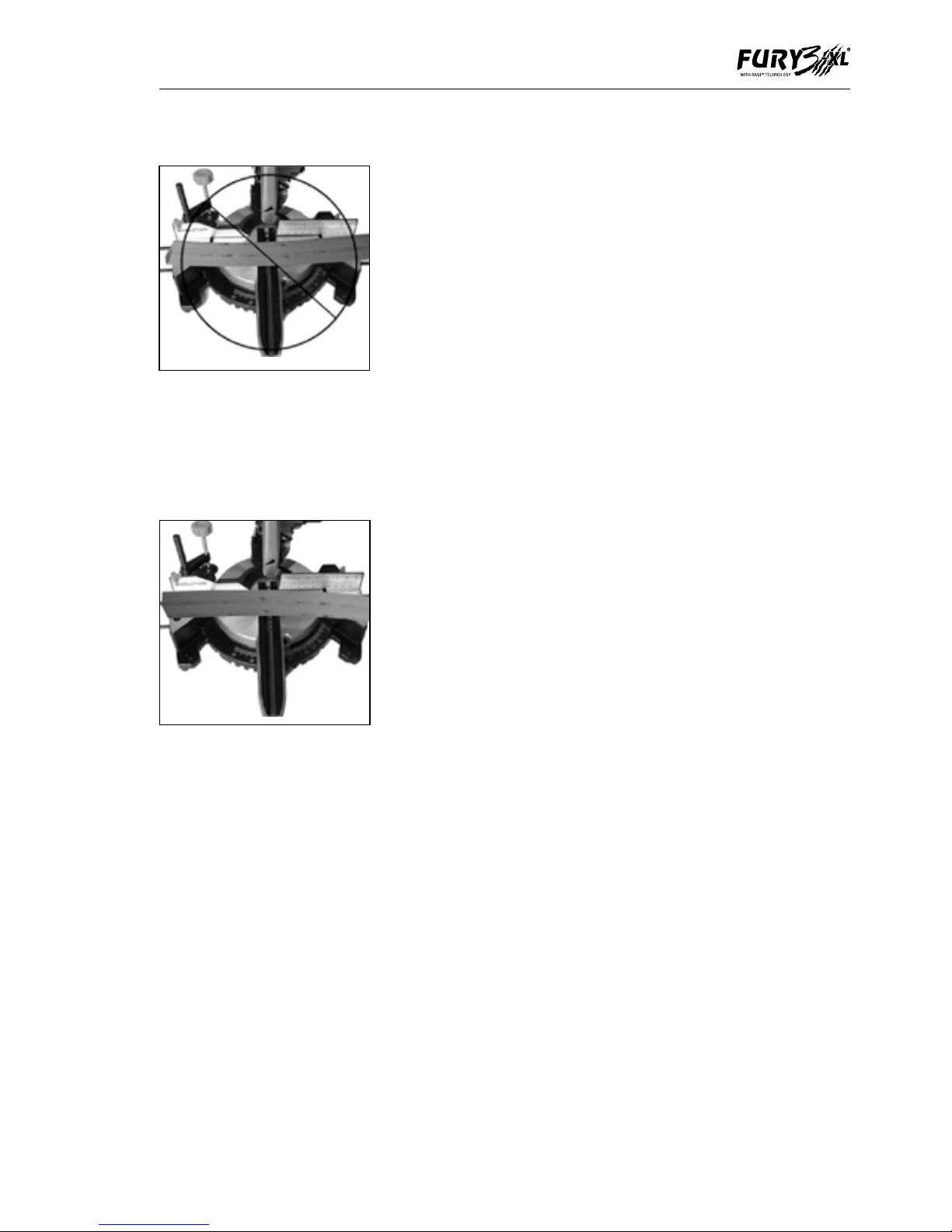
10. Cutting Bowed Material
Before cutting any workpiece, check to see if it is bowed.
If it is bowed the workpiece must be positioned and cut as
shown. See Figs 11 & 12
Do not position the workpiece incorrectly or cut the
workpiece without the support of the fence.
11. Clearing Jammed Material
1. Turn mitre saw “OFF” by releasing the trigger switch.
2. Allow the blade to come to a complete halt.
3. Unplug the mitre saw from the mains supply.
4. Remove any jammed material from the unit.
12. Transporting
When transporting the saw between locations make sure that:
1. The saw head is locked in the down position.
2. The rotary table mitre handle, the bevel locking lever and
the slide locking knob are all securely tightened.
3. The machines power cord is safely stored.
4. Use the transportation handle cut-outs on either side of
the machine base to lift the saw. Do not lift the saw by the
switch handle alone.
NOTE: Although compact this saw is quite heavy, Enlist
competent help, if necessary, when transporting this saw.
Fig 11
Fig 12
Page 18

18
www.evolutionfury.com
MAINTENANCE
Note
Any maintenance must be carried out with
the machine switched off and disconnected
from the mains power supply.
All motor bearings in this machine are
lubricated for life.
No further lubrication is required.
Apply light machine oil to the machines pivot
points and lower blade operating arm. Avoid
excessive oil, to which sawdust will cling.
Periodically, sawdust may accumulate under
the work table and the base. Use a vacuum
cleaner to remove this sawdust.
Use a clean, slightly damp cloth to clean
the plastic parts of the machine. Do not use
solvents or similar products which could
damage the plastic parts.
WARNING: Do not attempt to clean by
inserting pointed objects through openings in
the machines casings etc. The machines air
vents should be cleaned using compressed
dry air.
ENVIRONMENTAL PROTECTION
Waste electrical products should not be
disposed of with household waste. Please
recycle where facilities exist. Check with your
Local Authority or retailer for recycling advice.
®
MAINTENANCE
GB
ENVIRONMENTAL PROTECTION
GB
Page 19

19
www.evolutionfury.com
SERVICE PARTS LISTS
GB
Page 20

20
www.evolutionfury.com
TABLE DES MATIÈRES
Déclaration de conformité CE 20
Informations importantes 21
Garantie limitée de 12 mois 21
Règles de sécurité générales 21
Consignes de sécurité pour 22
toutes les scies
Règles de sécurité particulières 23
supplémentaires 25
Symboles et étiquettes de sécurité 27
Caractéristiques techniques 27
Vue d’ensemble de la machine 29
Assemblage 30
Fonctionnement 32
Maintenance 38
Protection environnementale 38
Listes de pièces de rechange 39
EC - DECLARATION OF CONFORMITY
Nous, fabricant et importateur,
Evolution Power Tools Ltd.
Venture One
Sheffield
S20 3FR
déclarons que le produit
Part numbers:
N° de référence : FURY32552, FURY32552EU
Evolution : Scie à onglet combiné à coulisse
multi-fonctions FURY 3 XL
est conforme aux prescriptions essentielles
des directives européennes suivantes :
2006/42/CE – Directive relative aux machines
2006/95/CE – Directive relative aux basses
tensions
2004/108/CE – Directive relative à la
compatibilité électromagnétique
2002/95/CE – Restrictions d’utilisation de
certaines substances dangereuses dans les
équipements électriques et électroniques
Cet outil est conforme aux normes
suivantes :
EN 61029-1:2009
EN 61029-2-9:2002
EN 55014-1:2006+A1:2009
EN 55014-2:1997+A1:2001+A2:2008
EN 61000-3-2:2006+A1:2009+A2:2009
EN 61000-3-3:2008
EN 60825-1:2007
Authorised by
M. Matthew J. Gavins
Directeur général
1er juin 2010
Toute la documentation est conservée à
l’adresse ci-dessus et est disponible pour
consultation sur demande.
®
DÉCLARATION DE CONFORMITÉ CE
FR
Page 21

21
www.evolutionfury.com
IMPORTANT
IMPORTANT
Lisez attentivement et intégralement
ces consignes d’utilisation et de sécurité
avant toute utilisation de l’outil. Pour votre
sécurité, vous devez vérifier, avant toute
utilisation, que la tension d’alimentation
est correcte et que toutes les poignées et
pièces de l’outil sont bien fixées. Si vous
avez la moindre incertitude concernant
l’utilisation de cet outil, n’hésitez pas
à contacter notre Service d’assistance
technique par téléphone.
Service d’assistance technique par
téléphone pour le Royaume-Uni
0870 609 2297
Service d’assistance technique par
téléphone pour les États-Unis
1-866-EVO-TOOL
Scie à onglet combiné à coulisse
multi-fonctions FURY 3XL de 255 mm
EVOLUTION
Nous vous félicitons d’avoir acheté une scie
à onglet combiné multi-fonctions de 255mm
d’Evolution Power Tools. Enregistrez votre
produit en ligne pour valider la période de
garantie de votre outil et bénéficier d’un
service rapide en cas de besoin. Nous vous
remercions sincèrement d’avoir choisi un
produit Evolution Power Tools.
GARANTIE LIMITEE DE 12 MOIS.
Evolution Power Tools se réserve le
droit d’apporter des améliorations et des
modifications à la conception de cet outil, et
ce sans préavis.
Evolution Power Tools réparera ou remplacera,
dans les douze (12) mois suivant la date
d’achat d’origine, tout article présentant
un vice de matériau ou un défaut de
fabrication. La présente garantie est sans
valeur si l’outil retourné a été utilisé pour
découper des matériaux non conformes
aux recommandations figurant dans le
présent manuel d’utilisation ou si la scie a été
endommagée par accident, par négligence ou
en raison d’un mauvais entretien. La présente
garantie ne s’applique pas aux machines et/
ou aux composants qui ont été altéré(e)s,
remplacé(e)s ou modifié(e)s d’une quelconque
manière, ou qui ont été utilisé(e)s sans
respecter les capacités et les spécifications
recommandées. Les composants électriques
sont couverts par les garanties offertes par
leurs fabricants respectifs. Tous les articles
défectueux doivent être retournés à Evolution
Power Tools en port prépayé. Evolution Power
Tools se réserve le droit, à sa seule discrétion,
de réparer l’outil ou de le remplacer par un
produit identique ou équivalent. Aucune
garantie – écrite ou verbale – ne couvre les
lames des scies. Evolution Power Tools
ne saurait en aucun cas être tenue pour
responsable des pertes ou dommages
découlant directement ou indirectement de
l’utilisation du produit ou de toute autre cause.
Evolution Power Tools ne saurait être tenue
pour responsable des coûts relatifs à ce produit
ou aux dommages accessoires y afférents.
Aucun cadre, employé ou agent de la société
Evolution Power Tools n’est habilité à faire
de déclarations verbales d’adéquation à un
usage particulier ou à déroger aux conditions
de vente précédentes : les déclarations de ce
type ne sauraient en aucun cas être opposées
à Evolution Power Tools. Toute question relative
à la présente garantie limitée doit être adressée
directement au siège social de la société.
Vous pouvez également appeler le Service
d’assistance technique téléphonique approprié.
CONSIGNES DE SÉCURITÉ IMPORTANTES
Afin de réduire le risque d’électrocution, cet
équipement est équipé d’un cordon électrique
et d’une fiche approuvés pour le pays
d’utilisation auquel il est destiné. Vous ne devez
en aucun cas changer le cordon ou la fiche.
RÈGLES DE SÉCURITÉ D’ORDRE GÉNÉRAL
Assurez-vous d’avoir lu et compris toutes
les consignes avant d’utiliser ce produit.
Le non-respect de toutes les consignes
énumérées ci-dessous pourrait entraîner des
décharges électriques, des incendies et/ou
des blessures graves.
INFORMATIONS IMPORTANTES
FR
GARANTIE LIMITÉE DE 12 MOIS
FR
RÈGLES DE SÉCURITÉ GÉNÉRALES
FR
Page 22

22
www.evolutionfury.com
CONSERVEZ CES CONSIGNES POUR
AVERTISSEMENT ! Lors de l’utilisation
d’outils électriques, les mesures de sécurité
de base devraient toujours être suivies afin
de réduire le risque d’incendie, de décharge
électrique et de blessures.
Lisez toutes ces consignes avant de tenter
d’utiliser cette machine. Conservez ce
manuel pour référence future.
1. Tenez votre lieu de travail propre.
Les endroits encombrés sont propices
aux accidents.
2. Pensez à l’environnement de votre lieu
de travail. N’exposez pas les outils à la pluie.
N’utilisez pas les outils dans des endroits
humides ou mouillés. Votre lieu de travail doit
être bien éclairé. N’utilisez jamais d’outils à
proximité de liquides ou de gaz inflammables.
3. Protégez-vous contre les décharges
électriques. Évitez le contact du corps avec
des surfaces mises à la terre ou à la masse.
4. Tenez les autres personnes à distance.
Ne laissez pas les autres, les enfants surtout,
s’approcher de votre travail et toucher l’outil
ou la rallonge. Tenez-les éloignés de votre lieu
de travail.
5. Rangez les outils quand vous avez fini
de vous en servir. Lorsque vous ne vous en
servez pas, rangez les outils dans un endroit
sec fermant à clé, hors de la portée des
enfants.
6. Ne forcez jamais les outils. Vos outils
seront plus efficaces et moins dangereux si
vous les utilisez à la puissance à laquelle ils
sont censés être utilisés.
7. Utilisez le bon outil. N’utilisez pas un petit
outil pour faire le travail d’un gros outil plus
puissant. N’utilisez pas les outils pour des
travaux pour lesquels ils ne sont pas prévus.
Par exemple, n’utilisez pas une scie circulaire
pour couper des arbres ou du bois.
8. Portez une tenue adaptée. Ne portez pas
de vêtements lâches ou de bijoux, car ils
pourraient se prendre dans des composants
mobiles. Portez de préférence des chaussures
antidérapantes lorsque vous travaillez à
l’extérieur. Si vous avez des cheveux longs,
attachez-les et couvrez-les.
9. Portez un équipement de protection.
Portez des lunettes de sécurité. Portez un
masque facial ou un masque à poussière si le
travail prévu va faire de la poussière.
10. Branchez un système d’extraction
de la poussière. Si la machine possède un
branchement pour un dispositif d’extraction
de la poussière, branchez-le et utilisez-le
correctement.
11. N’endommagez pas le cordon
électrique. Ne tirez jamais sur le cordon
électrique pour débrancher la machine.
Conservez le cordon éloigné de la chaleur,
de l’huile et des bords tranchants.
12. Bloquez la pièce. Si possible, utilisez des
pinces ou un étau pour la bloquer. Cela est
nettement moins dangereux que d’utiliser vos
mains.
13. N’essayez pas d’atteindre les endroits
inaccessibles. Veillez à toujours garder votre
équilibre.
14. Gardez vos outils en bon état de marche.
Gardez vos outils propres et affûtés pour des
résultats optimaux et pour travailler en toute
sécurité. Suivez les consignes de graissage et
de changement des accessoires. Inspectez
régulièrement les cordons d’alimentation. En
cas de dommage, faites-les remplacer par
un réparateur agréé. Inspectez les rallonges
périodiquement. Si elles sont abîmées,
remplacez-les. Gardez toujours les poignées
propres, sèches et sans huile ni graisse.
15. Débranchez les outils. Débranchez
les outils de la prise électrique lorsque
vous ne vous en servez pas, avant les
révisions/réparations et lors du changement
d’accessoires (lames, embouts, disques de
coupe, etc.).
16. Retirez les clavettes et clés de réglage.
Prenez pour habitude de contrôler que les
clavettes et clés de réglage ont été retirées de
l’outil avant de le mettre en marche.
17. Évitez les démarrages accidentels.
Contrôlez que l’interrupteur Marche/Arrêt est
sur la position Arrêt avant de brancher l’outil.
18. Utilisez des rallonges adaptées. Si vous
utilisez l’outil à l’extérieur, utilisez uniquement
une rallonge adaptée à une utilisation à
l’extérieur, ce qui doit être indiqué sur
l’étiquette de la rallonge.
®
CONSIGNES DE SÉCURITÉ POUR
TOUTES LES SCIES
FR
Page 23

23
www.evolutionfury.com
19. Restez alerte. Concentrez-vous sur ce
que vous faites, faites preuve de bon sens et
n’utilisez pas l’outil si vous êtes fatigué.
20. Contrôlez qu’aucun composant n’est
endommagé. Avant d’utiliser un outil,
assurez-vous qu’il est en bon état de marche.
Contrôlez l’alignement et l’état des pièces
en mouvement, les fixations et tous les
autres aspects susceptibles d’affecter son
fonctionnement. Si un carter de protection
ou un autre composant est endommagé,
faites-le réparer ou remplacer dans un centre
de réparation agréé, sauf indication contraire
figurant dans ce manuel. N’utilisez pas l’outil
si l’interrupteur ne le met pas en marche et à
l’arrêt.
21. Avertissement. L’utilisation d’accessoires
autres que ceux recommandés dans ce
manuel peut entraîner un risque de dommage
corporel.
22. Faites réparer votre outil dans un centre
de réparation agréé. Cet outil électrique est
conforme aux règles de sécurité en vigueur.
Les réparations ne doivent être effectuées que
par un réparateur agréé et avec des pièces de
rechange d’origine. Le non-respect de cette
consigne pourrait mettre l’utilisateur de l’outil
dans une situation très dangereuse.
CONSEILS DE SANTÉ
Avertissement !
Lorsque vous percez, poncez, sciez ou
meulez, des particules de poussière sont
produites. Dans certains cas, selon le
matériau utilisé, ces poussières peuvent
être très dangereuses pour la santé (plomb
contenu dans les anciennes peintures
brillantes, par exemple). Il est conseillé de
réfléchir aux risques associés aux matériaux
utilisés et de réduire le risque d’exposition.
Vous devriez :
- Travailler dans un endroit bien aéré.
- Travailler avec l’équipement de sécurité
approuvé, comme, par exemple, des
masques à poussière spécialement conçus
pour filtrer les particules microscopiques.
CONSIGNES DE SÉCURITÉ POUR
a) DANGER : Tenez vos mains éloignées
de la zone de coupe et de la lame. Placez
votre seconde main sur la poignée auxiliaire
ou sur le bloc moteur. En tenant la scie avec
vos deux mains, vous ne courrez aucun
risque d’être blessé par les lames.
b) Ne mettez pas vos mains sous la pièce
à couper. Le carter de protection ne peut
pas vous protéger de la lame dans ce cas.
c) Réglez la profondeur de coupe en
fonction de l’épaisseur de la pièce à
couper. Moins d’une dent entière de la lame
devrait être visible sous la pièce à couper.
d) Ne tenez jamais la pièce à couper dans
vos mains ou sur votre jambe. Bloquez la
pièce à couper sur un établi stable. Il importe
de soutenir correctement la pièce de façon à
réduire au minimum l’exposition du corps et
le risque de blocage de la lame ou de perte
de contrôle.
e) Tenez votre outil électrique par ses
surfaces de prise isolées lorsqu’il est
possible que l’outil de coupe entre en
contact avec des fils cachés ou son propre
cordon électrique. Le contact avec un fil
« sous tension » peut également mettre
les parties métalliques exposées de l’outil
électrique « sous tension » et vous risqueriez
alors de recevoir une décharge électrique.
f) Pour le sciage en long, utilisez toujours
un guide longitudinal ou un guide de chant.
Vous obtiendrez ainsi une coupe plus précise
et la lame risquera moins de se bloquer.
g) Utilisez toujours des lames avec des
trous d’arbre de la taille correcte et de
la forme appropriée (en losange/ronds).
Les lames qui ne sont pas adaptées au
dispositif de montage de la scie tourneront
excentriquement, ce qui vous fera perdre le
contrôle de l’outil.
h) N’utilisez jamais de rondelles ou
de boulons de lame endommagés ou
inadaptés. Les rondelles et le boulon des
lames ont été spécialement conçus pour
permettre à votre scie de développer des
performances optimales et pour offrir une
sécurité d’utilisation exemplaire.
CONSIGNES DE SÉCURITÉ SUPPLÉMENTAIRES
POUR VOTRE SCIE À ONGLET
FR
Page 24

24
www.evolutionfury.com
Autres consignes de sécurité pour toutes
les scies
Causes des reculs et comment les éviter :
Le recul est une réaction soudaine à une
lame de scie pincée, bloquée ou mal alignée,
qui amène une scie non contrôlée à se
soulever vers l’opérateur :
1. Lorsque la lame est pincée ou complètement
bloquée dans la saignée qui se referme, la
lame cale et la réaction du moteur ramène
rapidement la scie vers l’opérateur.
2. Si la lame se déforme ou devient mal
alignée dans la coupe, les dents du bord
arrière de la lame peuvent entrer dans la
surface supérieure de la pièce, ce qui peut
amener la lame à sortir de la saignée et à
sauter vers l’opérateur.
Le recul est le résultat d’une mauvaise
utilisation de la scie et/ou de conditions
ou procédures d’utilisation incorrectes. Il
peut être évité en prenant les mesures de
précaution décrites ci-dessous.
a) Tenez fermement la scie des deux mains
et positionnez vos bras de façon à résister
aux forces de recul. Positionnez votre corps
d’un côté ou de l’autre de la lame, mais pas
dans l’alignement de la lame. Le recul peut
amener la scie à sauter vers l’arrière, mais
vous pouvez maîtriser les forces de recul en
prenant certaines précautions.
b) Lorsque la lame se bloque, ou lors de
l’interruption de la coupe pour quelque
raison que ce soit, relâchez le déclencheur
et gardez la scie immobile dans le
matériau jusqu’à ce que la lame s’arrête
complètement. Ne tentez jamais de retirer
la scie de la pièce ou de tirer la scie vers
l’arrière lorsque la lame est en mouvement,
car la scie risque de reculer. Recherchez la
cause du blocage de la lame et prenez les
mesures correctives qui s’imposent.
c) Lorsque vous redémarrez une scie
dans la pièce à couper, centrez la lame
de la scie dans la saignée et contrôlez
que les dents de la scie ne sont pas
engagées dans le matériau. Si la lame se
bloque, elle risque de sauter ou de reculer au
redémarrage de la scie.
d) Soutenez les grands panneaux de
façon à réduire le risque de pincement
et de recul de la lame au minimum. Les
grands panneaux ont tendance à s’arquer
sous leur propre poids. Placez des supports
sous le panneau, des deux côtés, près de la
ligne de coupe et près du bord du panneau.
e) Contrôlez que les leviers de
verrouillage du réglage du biseau et de la
profondeur de la lame sont bien serrés et
bloqués avant de couper. Si le réglage de
la lame change pendant la coupe, il pourra y
avoir blocage et recul.
f) N’utilisez jamais de lames émoussées
ou endommagées. Des lames de scie
mal affutées ou mal posées produiront une
saignée étroite, ce dont il résultera une
friction excessive. La lame se bloquera alors
et reculera.
g) Faites extrêmement attention pendant
le « sciage en plongée » dans des murs
ou autres zones aveugles. La lame en
saillie peut couper des objets, ce qui peut
provoquer un recul.
Consignes de sécurité concernant les scies
a) Avant chaque utilisation, contrôlez
que le carter de protection inférieur se
ferme comme il faut. N’utilisez pas la
scie si le carter de protection inférieur ne
bouge pas librement et ne se ferme pas
instantanément. Ne bloquez jamais le carter
de protection inférieur en position ouverte.
En cas de chute accidentelle de la scie, le
carter de protection inférieur risque de se
déformer. Soulevez le carter de protection
inférieur au moyen de la poignée rétractable
et assurez-vous qu’il bouge librement et qu’il
n’est pas en contact avec la lame ou avec un
autre composant de l’outil, et ce à tous les
angles et profondeurs de coupe.
b) Contrôlez le fonctionnement du
ressort du carter de protection inférieur.
Si le carter de protection et le ressort ne
fonctionnent pas correctement, ils doivent
être réparés avant toute utilisation. Il est
possible que le carter de protection inférieur
ne fonctionne pas très bien en raison de
composants endommagés, de dépôts
collants ou d’une accumulation de débris.
c) Le carter de protection inférieur peut
être rentré manuellement uniquement
pour les coupes spéciales (en plongée,
combinée, etc.). Soulevez le carter de
®
Page 25

25
www.evolutionfury.com
protection inférieur par la poignée rétractable
et relâchez-le dès que la lame entre dans
le matériau. Pour toutes les autres coupes,
le carter de protection inférieur devrait
fonctionner automatiquement.
d) Contrôlez toujours que le carter de
protection inférieur couvre la lame avant
de poser la scie sur l’établi ou le sol. Une
lame non protégée qui continue à avancer
fera reculer la scie, qui coupera alors tout ce
qui se trouvera sur son chemin. La lame met
un peu de temps à s’arrêter après que vous
appuyez sur le bouton d’arrêt.
ADDITIONAL SAFETY INSTRUCTIONS
Avertissement : vous devez avoir lu et
compris toutes les consignes avant d’utiliser
cet outil. Le non-respect des consignes
énumérées ci-dessous pourrait entraîner des
décharges électriques, des incendies et/ou
des blessures graves.
a) Conservez tous les carters de protection
en place et en bon état de marche.
b) Retirez les clavettes et clés de réglage.
Prenez pour habitude de contrôler que les
clavettes et clés de réglage ont été retirées
de l’outil avant de le mettre en marche.
c) Tenez votre lieu de travail propre.
Les endroits et les établis encombrés sont
propices aux accidents.
d) N’utilisez pas l’outil dans des lieux
dangereux. N’utilisez pas les outils
électriques dans des endroits humides ou
mouillés et ne les exposez pas à la pluie.
Votre lieu de travail doit être bien éclairé.
e) Tenez les enfants à l’écart. Tous les
visiteurs devraient être tenus à bonne
distance du lieu de travail.
f) Ne forcez pas l’outil. Il fera un meilleur
travail et sera moins dangereux s’il est utilisé
à la puissance pour laquelle il a été conçu.
g) Utilisez une rallonge appropriée. Si
vous utilisez une rallonge, contrôlez qu’elle
est en bon état. Si vous utilisez une rallonge,
assurez-vous qu’elle est suffisamment forte
pour transporter le courant que votre outil
tirera. Si elle est trop faible, cela entraînera
une chute de la tension sectorielle, ce qui se
traduira par une perte de puissance et une
surchauffe de votre outil.
h) Portez une tenue adaptée. Ne portez
pas de vêtements flottants, de gants, de
foulards, de bagues, de bracelets ou autres
bijoux susceptibles de se prendre dans les
pièces en mouvement. Il est conseillé de
porter des chaussures non glissantes. Portez
quelque chose sur la tête pour maintenir vos
cheveux attachés s’ils sont longs.
i) Portez toujours des lunettes de
sécurité. Portez également un masque facial
ou un masque à poussière si le travail prévu
va faire de la poussière. Les verres des
lunettes ordinaires offrent une résistance
aux chocs uniquement. Ce NE sont PAS des
lunettes de sécurité.
j) Bloquez la pièce à découper. Utilisez
des pinces pour bloquer la pièce à découper
lorsque cela est possible. Cela est moins
risqué que de tenir la pièce avec vos mains et
cela libère vos deux mains pour manier l’outil.
k) N’essayez pas d’atteindre les endroits
inaccessibles. Veillez à toujours garder votre
équilibre.
l) Prenez soin de vos outils. Gardez vos
outils propres et affûtés pour des résultats
optimaux et pour travailler en toute sécurité.
Suivez les consignes de graissage et de
changement des accessoires. N’utilisez pas
de lames pour l’acier à coupe rapide ni de
lames endommagées ou déformées.
m) Débranchez l’outil avant toute
réparation et avant de changer des
accessoires (lames, etc.).
n) Réduisez le risque de démarrage
accidentel. Contrôlez que l’interrupteur
Marche/Arrêt est sur la position Arrêt avant
de brancher l’outil.
o) Utilisez les accessoires recommandés.
Utilisez uniquement des accessoires
d’origine Evolution garantie. Utilisée avec la
bonne lame (lame TCT multi-fonctions Fury
3), cette scie est recommandée pour couper
l’acier doux, l’aluminium et le bois.
p) Ne montez jamais sur l’outil. Des
blessures graves pourraient survenir si l’outil
bascule ou si vous entrez accidentellement
en contact avec l’outil de coupe.
q) Contrôlez qu’il n’y a pas de pièces
d’endommagées. Si vous constatez qu’un
carter de protection ou un autre composant est
endommagé, examinez-le soigneusement afin
RÈGLES DE SÉCURITÉ PARTICULIÈRES
SUPPLÉMENTAIRES
FR
Page 26

26
www.evolutionfury.com
de déterminer s’il fonctionnera correctement
et s’acquittera de sa fonction avant de
continuer à utiliser l’outil. Contrôlez que les
pièces en mouvement sont correctement
alignées et qu’elles ne sont pas bloquées,
qu’il n’y a pas de composants de cassés,
que la monture est en parfait état et qu’il n’y
a pas d’autres problèmes susceptibles de
nuire au bon fonctionnement de l’outil. Si un
carter de protection ou un autre composant
est endommagé, faites-le réparer par un
réparateur agréé ou remplacez-le.
r) Éloignez vos mains du parcours de la
lame de la scie.
s) N’approchez jamais vos mains de la lame.
t) Mettez l’outil hors tension et attendez
que la lame se soit arrêtée avant de
changer les pièces à découper de position
ou de modifier les réglages.
u) Débranchez l’outil de la prise électrique
avant de changer la lame, d’effectuer des
réparations ou de nettoyer l’outil.
v) Pour réduire le risque de blessures,
ramenez le chariot en position arrière
complète après chaque coupe transversale.
Comment transporter votre scie à onglet
Consignes de sécurité
1. Bien que compacte, la scie est lourde. Pour
ne pas vous faire mal au dos, faites-vous aider
chaque fois que vous devez la soulever.
2. Pour éviter de vous faire mal au dos,
tenez l’outil près de votre corps pour le
soulever. Pliez les genoux pour pouvoir
soulever l’outil avec vos jambes, au lieu de
votre dos. Soulevez l’outil en le prenant par
les zones de prise qui se trouvent sur le
dessous du socle, de chaque côté.
3. Ne portez jamais la scie à onglet en la tenant
par le cordon électrique ou par le déclencheur
de la poignée. Si vous la portez par le cordon,
vous risquez d’endommager l’isolation ou les
fils de raccordement, ce dont il peut résulter
une électrocution ou un incendie.
4. Avant de déplacer la scie, serrez le bouton
de blocage de la coulisse pour empêcher les
mouvements soudains.
AVERTISSEMENT !
Ne soulevez pas l’outil par le carter de lame.
Débranchez le cordon de la prise de courant
avant d’essayer de déplacer la machine.
• Bloquezlatêteàl’aidedelagoupillede
blocage de tête.
• Amenezlatêtedecoupeàsapositionla
plus éloignée et bloquez-la en serrant le
bouton de blocage de la coulisse.
• Desserrezleboutondeblocagedel’angle
d’onglet. Tirez le levier d’angle d’onglet et
faites tourner la table pour l’amener sur un
de ses réglages maximum.
• Bloquezlatableàl’aideduboutonde
blocage.
• Pourtransporterlamachine,servez-vous
des deux poignées découpées de chaque
côté du socle de la machine.
Posez la scie sur une surface de
travail fixe et sécurisée et inspectez
la scie soigneusement. Contrôlez tout
particulièrement le fonctionnement de tous
les dispositifs de sécurité de la machine
avant sa mise en service ou son utilisation.
®
Page 27

27
www.evolutionfury.com
SAFETY LABELS & SYMBOLS
AVERTISSEMENT !
N’utilisez en aucun cas la machine s’il
manque des autocollants contenant des
avertissements et/ou des consignes ou
si ces autocollants sont endommagés.
Contactez Evolution Power Tools pour
obtenir des étiquettes de rechange.
Symbole Description
V Volts
A Ampères
Hz Hertz
min
-1
Vitesse
~ Courant alternatif
n0
Vitesse à vide
Double isolation
Wear Safety
Goggles
Wear Ear Protection
Ne pas toucher
Portez une protection
contre la poussière
Directive relative
à la restriction
d'utilisation de
certaines substances
dangereuses
Certification CE
Déchets
d'équipements
électriques et
électroniques
Utilisez uniquement des lames de rechange
d’origine Evolution garantie. Les lames non
autorisées peuvent être dangereuses ! Les
lames de la scie doivent être solidement
fixées. Vérifiez qu’aucun débris ne se trouve
sur les flasques de la lame avant d’installer
une nouvelle lame. N’utilisez jamais de lames
émoussées, cassées ou endommagées.
Vérifiez fréquemment l’état et le degré
d’usure des lames. Les lames endommagées
ou usées doivent être remplacées
immédiatement. Faites attention aux copeaux
qui sont éjectés. Ils sont peut-être CHAUDS.
Manipulez toujours l’excédent de matériau
avec précaution. Le socle de la machine
et la table rotative doivent toujours rester
dépourvus de saletés et autres débris.
Pour obtenir un nouvel exemplaire du présent
manuel d’utilisation, contactez Evolution
Power Tools :
Royaume-Uni 0870 609 2297
États-Unis 1-866-EVO-TOOL
SITE WEB www.evolutionpowertools.com
FURY 3 XL SPECIFICATION
Peut couper :
Tôle en acier doux – Épaisseur max. : 3
mm
Profilés en caisson en acier doux –
Épaisseur de paroi max. : 3 mm
Aluminium
Bois – Section max. : 75 mm x 300 mm
Données techniques
Moteur (230 V ~ ou 110 V ~ 50/60 Hz) (Watts) :
2 000 W (démarrage progressif)
Vitesse de rotation à vide (min-1) :
2500
Cycle de service max. conseillé (minutes) :
30 minutes
Poids : 17,85 Kg
Dimensions de la lame
Diamètre : 255 mm
Nombre de dents : 24
Diamètre d’alésage : 25,4 mm
Épaisseur : 2 mm
Capacité de coupe maximale (bois)
À 900 (onglet) x 900 (biseau)
300 mm x 75 mm
À 450 (onglet) x 900 (biseau)
210 mm x 75 mm
À 450 (onglet) x 450 (biseau)
210 mm x 40 mm
SYMBOLES ET ÉTIQUETTES DE SÉCURITÉ
FR
SPECIFICATION
FR
Page 28

28
www.evolutionfury.com
Niveau sonore et vibrations
Niveau de pression acoustique :
88,1 dB(A) K=3 dB(A)
Niveau de puissance acoustique :
99,8 dB(A) K=3 dB(A)
Niveau de vibrations :
1,059 m/s2 K =1,5 dB(A)
La valeur de vibrations totale déclarée a été
mesurée selon une méthode d’essai standard
et peut être utilisée pour comparer un outil
avec un autre.
La valeur de vibrations totale déclarée peut
également servir d’évaluation d’exposition
préliminaire.
AVERTISSEMENT : la valeur d’émission
de vibrations pendant l’utilisation de l’outil
électrique peut être différente de la valeur
totale déclarée, selon la façon dont l’outil est
utilisé. Il est nécessaire de déterminer les
mesures de sécurité à adopter et de protéger
l’opérateur en fonction d’une estimation de
l’exposition dans les conditions effectives
d’utilisation (en tenant compte de toutes les
étapes du cycle d’exploitation, par exemple
lorsque l’outil est mis à l’arrêt, lorsqu’il tourne
au ralenti, en plus du déclenchement).
ACCESSOIRES SUPPLÉMENTAIRES
En plus des accessoires standard fournis
avec la machine, d’autres accessoires sont
disponibles pour améliorer ses performances,
à savoir :
1. Système de serrage – Cette machine a
été étudiée de façon à permettre l’utilisation
d’une pince avant qui peut être posée
d’un côté ou de l’autre de la lame dans les
logements du socle.
2. Lame de diamant – Transformez cette scie
en machine à couper les carreaux. Il suffit
de remplacer la lame TCT standard par la
lame de diamant en option pour transformer
cette scie en machine à couper les carreaux
compatible avec la plupart des carreaux en
céramique ou en porcelaine.
D’autres accessoires sont disponibles auprès
de votre concessionnaire local (ou d’Evolution
Power Tools).
ITEM QUANTITY
Manuel d'utilisation 1
Clé hexagonale 1
Pince supérieure 1
Lame multifonctions 1 FURY3-XL
Barres de soutien 2
Butée de fin de course 1
®
Page 29

29
www.evolutionfury.com
MACHINE OVERVIEW
FR
1. DÉCLENCHEUR MARCHE/ARRÊT
2. DÉCLENCHEUR DE BLOCAGE DU
CARTER DE LAME
3. POIGNÉE DE COUPE
4. SAC À POUSSIÈRE EXTRACTION DU PORT
5. TABLE ROTATIVE
6. DESSUS DE TABLE
7. CARTER DE LAME INFÉRIEUR
8. CARTER DE LAME SUPÉRIEUR
9. LAME
10. BOUTON DE BLOCAGE DE LA COULISSE
11. LEVIER DE BLOCAGE DU BISEAU
12. POIGNÉE D’ONGLET
13. RAPPORTEUR D’ONGLET
14. LEVIER DE BLOCAGE DE BUTÉE FIXE
15. SUPPORT DE PIÈCE
16. BUTÉE DE REPRISE
17. GUIDE
18. PINCE SUPÉRIEURE
19. GOUPILLE DE BLOCAGE DE TÊTE
20. TROU DE FIXATION
2
4
2
19
11
15
6
17
5
14
7
9
3
8
12
20
1
13
10
16
18
Page 30

30
www.evolutionfury.com
GETTING STARTED
MISE EN GARDE ! DÉBRANCHEZ TOUJOURS LA SCIE DU
SECTEUR AVANT DE PROCÉDER AU MOINDRE RÉGLAGE.
Refer to the “Service Parts List Drawing”. Install a blade as
detailed in the “Installing or Removing the Blade” section.
Reportez-vous au dessin de liste des pièces de rechange.
Mettez une lame en place en procédant comme indiqué dans
la section « Pose ou retrait de la lame ».
1. Montage de la scie à onglet
AVERTISSEMENT : afin de réduire le risque de blessures
causées par les mouvements inopinés de la scie, posez la
scie à l’endroit désiré, sur un établi ou autre table de travail
recommandée. À la base de la scie, vous verrez quatre trous
qui sont réservés au montage de la scie à onglet. Si la scie
est destinée à être utilisée à un seul endroit, fixez-la de
manière définitive sur l’établi ou la table de travail à l’aide de
boulons adaptés et de rondelles et écrous.
1. Serrez les systèmes de blocage d’onglet, de biseau et de
coulisse.
2. Placez la scie à un endroit où personne d’autre ne peut se
tenir derrière. Les projections de débris peuvent causer des
blessures.
3. Posez la scie sur une surface ferme et plane, où vous
aurez largement la place de manipuler la pièce à découper
et où cette dernière sera correctement soutenue.
4. Calez la scie de façon à ce que la table soit plane et à ce
que la scie ne puisse pas osciller.
5. Fixez la scie sur son support à l’aide de boulons ou de pinces.
2. Pose ou retrait de la lame
AVERTISSEMENT ! Utilisez uniquement des lames
Evolution d’origine garantie spécialement destinées à cette
machine. Contrôlez que la vitesse maximale de la lame est
compatible avec la machine. N’effectuez cette opération
qu’une fois la machine débranchée de la prise murale.
REMARQUE : il est conseillé à l’opérateur d’envisager le
port de gants de protection lors de la manipulation de la lame
pendant la pose ou le changement de lame.
1. Contrôlez que la tête de coupe se trouve en haut.
2. Déposez la pince de fixation du bras de commande du
carter (Fig. 1). Débloquez le bras de commande du carter de
protection de son pivot.
3. Appuyez sur le déclencheur de blocage du carter de lame
inférieur et soulevez le carter de lame inférieur (Fig. 2).
4. Appuyez sur le bouton de blocage d’arbre noir pour
®
Fig 1
Fig 2
Fig 3
DÉMARRAGE
FR
Page 31

31
www.evolutionfury.com
Fig 4
bloquer l’arbre (Fig. 3).
5. À l’aide de la clé hexagonale fournie, desserrez la vis de
l’arbre pour retirer la lame (Fig. 4).
Remarque : la vis de l’arbre possède un filet à gauche.
6. Posez la nouvelle lame de 255 mm. Contrôlez que la
flèche de rotation figurant sur la lame correspond à la flèche
de rotation dans le sens des aiguilles sur le carter supérieur.
Remarque : les dents de la lame devraient toujours être
orientées vers le bas à l’avant de la scie.
7. Posez la rondelle de la lame et la vis de l’arbre.
8. Serrez la vis de l’arbre en exerçant une force modérée.
Ne serrez pas trop.
9. Remettez le bras de commande de carter en place ainsi
que sa pince de fixation (Fig. 1).
10. Contrôlez que la clé a bien été retirée et que le bouton de
blocage de l’arbre a été débloqué avant d’utiliser la machine.
11. Contrôlez que le carter de lame est parfaitement
fonctionnel avant d’utiliser la machine.
Remarque : n’utilisez pas d’entretoises ni de bagues de
broche avec la machine et/ou la lame.
3. Sac de récupération de débris
Le sac de récupération de débris devrait être fixé sur l’orifice
d’évacuation des débris.
1. Faites glisser l’armature du sac de récupération sur
l’ouverture de l’orifice d’évacuation, en vous assurant qu’il
est solidement posé.
2. Pour retirer le sac, faites glisser l’armature dans le sens
opposé.
Remarque : pour une récupération des poussières optimale,
videz le sac lorsqu’il est plein aux deux tiers environ.
AVERTISSEMENT : avant de couper du métal, retirez le sac
de récupération et posez un obturateur à la place.
Remettez le sac de récupération en place lorsque vous
coupez du bois.
4. Pose de la butée de reprise
1. Desserrez les vis de serrage à main de la butée de reprise
suffisamment pour permettre aux bras du support de pièce
de glisser dans les trous de la butée de reprise.
2. Serrez les vis de serrage à main fermement afin de
réduire au minimum le mouvement sur le support de pièce.
Positionnez la butée de reprise à peu près à mi-chemin sur le
support de pièce.
3. Fixez le support de pièce sur le socle de la machine de la
Page 32

32
www.evolutionfury.com
manière décrite ci-dessous.
Remarque : en desserrant les vis de serrage à main, vous
pouvez régler la butée de reprise sur la distance requise par
rapport à la lame de la scie pour les opérations de coupe
répétitives, etc. Normalement, la butée est positionnée sur le
côté droit de la lame.
5. Pose du support de pièce (Fig. 5)
Les supports de pièce peuvent être montés des deux côtés
du socle de la machine si nécessaire.
1. Côté droit. Desserrez la vis de fixation du support située
en haut sur le devant du socle de la machine.
2. Insérez le support de pièce dans les trous de fixation du
socle. Contrôlez qu’il est bien fixé.
Remarque : environ 70 mm du support de pièce devraient
glisser dans le socle pour une bonne fixation.
3. Serrez la vis de fixation.
4. Procédez de même pour le côté gauche.
6. Pose de la pince de blocage de pièce supérieure (Fig. 6)
Deux logements (un de chaque côté) ont été prévus au dos
du guide de la machine.
1. Posez la pince dans le logement le plus approprié au travail
prévu, en veillant à ce qu’elle soit complètement enfoncée.
2. Serrez la vis de serrage à main du guide pour bloquer le
pilier dans le logement.
3. Placez la pièce à découper sur le banc de la scie.
4. Réglez la pince à l’aide de la vis de serrage à main et du
volant de façon à ce qu’elle maintienne solidement la pièce
sur le banc de la scie. La pince ne doit pas gêner la lame.
OPERATING INSTRUCTIONS
Mise en garde : inspectez la scie à onglet (et en particulier
le fonctionnement des carters de protection) avant chaque
utilisation. Ne branchez pas la scie sur le secteur tant que
cette inspection n’a pas été réalisée.
Assurez-vous que l’opérateur est suffisamment formé à
l’utilisation, au réglage et à l’entretien de la machine avant
de la mettre sous tension et de l’utiliser.
AVERTISSEMENT : afin de réduire le risque de blessures,
débranchez toujours la scie avant de changer un composant
ou d’effectuer un réglage. Comparez le sens de rotation
indiqué par la flèche figurant sur le carter avec celui de la
flèche figurant sur la lame. Les dents de la lame devraient
®
Fig 5
Fig 6
CONSIGNES D’UTILISATION
FR
Page 33

33
www.evolutionfury.com
Fig 7
toujours être orientées vers le bas à l’avant de la scie.
Contrôlez que la vis de l’arbre est bien serrée.
Guide laser
Cette scie est équipée d’un guide de coupe laser. Il permet
à l’utilisateur de prévisualiser la trajectoire de la lame sur la
pièce. Le bouton Marche/Arrêt du guide laser se trouve sur
le dessus du carter du moteur (Fig. 7).
Évitez le contact direct avec les yeux et ne l’utilisez pas sur
un matériau susceptible de réfléchir le faisceau laser.
AVERTISSEMENT : Ne regardez pas directement le faisceau
laser. Regarder délibérément le faisceau vous expose à un
risque. Respectez toutes les règles de sécurité qui suivent.
• Nedirigezpasdélibérémentlefaisceaulaserverslepersonnel
et ne le dirigez pas non plus sur les yeux d’une personne.
• Veilleztoujoursàcequelefaisceaulaserviseuniquement
des pièces à découper dont la surface n’est pas
réfléchissante (bois ou surfaces rugueuses, par exemple).
• Neremplacezpaslemodulelaserparunautred’untype
différent.
• Lesréparationsdumodulelaserdoiventêtreconées
à Evolution Power Tools ou son représentant agréé
uniquement.
Position du corps et des mains
1. Ne placez jamais vos mains près de la zone de coupe et
tenez-les éloignées du parcours de la lame.
2. Tenez fermement la pièce contre le guide pour l’empêcher
d’aller vers la lame. Utilisez une pince si nécessaire mais veillez
à ce qu’elle soit placée à un endroit ne gênant pas la lame.
3. Avant de faire une coupe, faites un essai à sec, scie hors
tension, pour voir le trajet de la lame.
4. Ne changez pas vos mains de position tant que le
déclencheur Marche/Arrêt n’a pas été relâché et que la scie
ne s’est pas complètement arrêtée.
1. Déblocage de la tête de scie
a) Appuyez délicatement sur la poignée de coupe.
b) Sortez la goupille de blocage de la tête et laissez la tête
monter jusqu’à sa position supérieure.
Remarque
Lorsque vous ne vous servez pas de la machine, nous
vous conseillons de bloquer la tête de coupe à sa position
inférieure et de laisser la goupille de blocage entièrement
enfoncée dans son logement.
2. Allumage de la machine
Branchez la machine sur l’alimentation électrique. Vérifiez que
le câble d’alimentation ne peut s’emmêler autour d’une partie
quelconque de la machine et qu’il n’est pas à proximité de la
Page 34

34
www.evolutionfury.com
lame ou du tableau. Appuyez sur le bouton de blocage situé
sur la garde inférieure puis appuyez sur le bouton On/Off pour
démarrer la scie. Relâchez le bouton pour arrêter la scie.
Laissez le toujours le moteur atteindre sa vitesse maximale
avant de commencer à couper.
3. Préparation avant la coupe
Mise en garde : NE tirez JAMAIS la scie vers vous pendant
une coupe. La lame pourrait sauter par dessus la pièce d’un
seul coup et se diriger vers vous.
•Évitezlesopérationsetlespositionsdesmainsingrates,
car il suffirait d’un écart soudain pour que vos doigts ou
votre main se prennent dans la lame.
•Necoupezjamaisplusd’unepièceàlafois.
•Éloigneztouslesobjetsdelalame,àl’exceptiondela
pièce à découper et de ses dispositifs de maintien,
avant de mettre la scie à onglet en marche.
•Bloquezlapièceàdécouperàl’aidedespincespour
l’empêcher de bouger.
4. Coupes à coulisse
Cette scie est équipée d’un système de chariot coulissant.
Desserrez le bouton de blocage de la coulisse pour
débloquer la coulisse et permettre à la tête de coupe
d’avancer et de reculer.
La lame de la scie est ensuite abaissée dans la pièce et
poussée vers l’arrière de la scie pour effectuer la coupe. Ce
type de coupe peut être utilisé pour couper de grandes pièces.
1. Placez la pièce contre le guide et bloquez-la à l’aide de pinces.
2. Desserrez le bouton de blocage de la coulisse.
3. Saisissez la poignée de la scie et tirez la tête de coupe
jusqu’à ce que l’arbre (centre de la lame de la scie) se trouve
au-dessus du bord avant de la pièce.
4. Appuyez sur le déclencheur de blocage du carter de lame
inférieur pour débloquer la tête de coupe.
5. Mettez la scie en marche et attendez qu’elle ait atteint sa
vitesse de pleine marche.
6. Abaissez complètement la poignée de la scie et coupez le
bord d’attaque de la pièce.
7. Poussez doucement la poignée de la scie vers le guide
pour effectuer la coupe.
8. Amenez la tête de coupe à sa position arrière complète
après chaque coupe.
9. Relâchez le déclencheur pour éteindre la scie. Attendez
que la lame se soit complètement arrêtée avant de changer
vos mains de position ou de retirer la pièce.
®
Page 35

35
www.evolutionfury.com
5. Fente – Consiste à serrer le bouton de blocage de la
coulisse pour bloquer la tête de coupe à sa position la plus
reculée. Pour couper la pièce, il faut pousser délicatement
la poignée de la scie. Ce type de coupe est principalement
utilisé pour les pièces étroites.
1. Faites glisser la tête de coupe vers l’arrière, jusqu’à ce
qu’elle bute.
2. Serrez le bouton de blocage de la coulisse.
3. Placez la pièce sur la table et contre le guide, et bloquez-la
avec des pinces.
4. Saisissez la poignée de la scie.
5. Mettez la scie en marche et attendez qu’elle ait atteint sa
vitesse de pleine marche.
6. Appuyez sur le déclencheur de blocage du carter inférieur
pour débloquer la tête de la scie.
7. Poussez la poignée de la scie vers le bas et coupez la pièce.
8. Une fois la coupe terminée, éteignez la scie et attendez
que la lame se soit complètement arrêtée avant de déplacer
vos mains ou de retirer la pièce.
AVERTISSEMENT : par souci de commodité, la scie est
équipée d’un frein de lame. Il ne doit en aucun cas remplacer
un bon usage du carter de la scie.
6. Coupe d’onglet (Fig. 8)
Cet outil permet d’obtenir un angle de jusqu’à 45°, à gauche
ou à droite. Des butées fixes sont fournies à 15°, 22,5°, 30°
et 45° à droite et à gauche.
1. Desserrez le bouton de blocage de la coulisse, poussez la
tête de coupe vers l’arrière jusqu’à ce qu’elle bute et bloquez
la coulisse.
2. Desserrez le bouton de blocage de l’angle d’onglet.
3. Sortez le levier de blocage de la butée fixe.
4. Faites tourner la table rotative jusqu’à ce que vous ayez obtenu
l’angle désiré, comme indiqué sur l’indicateur d’angle d’onglet.
5. Serrez le bouton de blocage de l’angle d’onglet pour
conserver l’angle désiré.
6. Si nécessaire, débloquez la tête de coupe en desserrant
le bouton de blocage de la coulisse. Cela permet à la tête de
coupe d’avancer et de reculer (ce qui est nécessaire pour
découper des planches larges).
7. Démarrez la scie et attendez qu’elle ait atteint sa vitesse
de pleine marche avant de commencer à couper.
Fig 8
Page 36

36
www.evolutionfury.com
7. Coupe en biseau à gauche (Fig. 9)
1. Bloquez la tête de coupe à l’aide de la goupille de blocage
de tête.
2. Desserrez le levier de blocage de biseau.
3. Inclinez la tête de coupe selon l’angle requis. Aidez-vous
du rapporteur gradué et de l’aiguille pour le réglage. Vous les
trouverez juste derrière le levier de blocage de biseau.
4. Serrez le levier de blocage de biseau.
5. Débloquez la tête de coupe.
6. Débloquez la coulisse (si nécessaire) pour couper les
pièces larges.
7. Placez-vous à gauche de la poignée pour faire la coupe.
8. Coupe combinée
La coupe combinée est une combinaison de coupe en onglet
et de coupe en biseau.
Lorsqu’une coupe combinée est nécessaire, sélectionnez les
positions de biseau et d’onglet désirées de la manière décrite
plus haut.
9. Butée de profondeur (Fig. 10)
La butée de profondeur permet de réaliser des rainures dans
la pièce. Vous pouvez régler la course vers le bas de la tête
de la scie de façon à ce que la scie ne fasse pas une coupe
complète dans la pièce.
Remarque : il est conseillé de contrôler la profondeur de coupe
sur un bout de bois d’essai avant de passer à votre pièce.
En réalisant une coupe dans la pièce puis en repositionnant
légèrement la pièce à gauche ou à droite avant de
recommencer, il est possible d’effectuer des coupes en
rainurage dans la pièce.
Pour utiliser la butée de profondeur, procédez comme suit :
1. Desserrez l’écrou à oreilles.
2. Ajustez le bouton pour limiter la course de la tête de la
scie jusqu’à la profondeur requise.
3. Une fois la profondeur désirée réglée, serrez l’écrou à
oreilles sur le support de fixation pour bloquer la butée de
profondeur et contrôlez qu’il n’y a pas de mouvement.
4. Une fois la coupe terminée, reréglez la butée de
profondeur de façon telle que la tête de coupe puisse être
bloquée à la position inférieure à l’aide de la goupille de
blocage de tête.
®
Fig 9
Fig 10
Page 37

37
www.evolutionfury.com
10. Coupe de pièces arquées
Avant de couper une pièce, contrôlez qu’elle n’est pas
arquée. Si elle est arquée, positionnez-la et coupez-la de la
manière illustrée. Cf. Fig. 11 et 12.
Il faut impérativement positionner la pièce correctement et
ne pas essayer de la couper sans le support du guide.
11. Comment résoudre les bourrages
1. Mettez la scie à onglet à l’arrêt en relâchant le
déclencheur.
2. Attendez que la lame se soit complètement arrêtée.
3. Débranchez la scie à onglet de la prise murale.
4. Retirez le matériau bloqué.
12. Transport
Lorsque vous transportez la scie d’un endroit à un autre,
tenez compte de ce qui suit :
1. La tête de la scie doit être bloquée sur la position inférieure.
2. La poignée d’onglet de la table rotative, le levier de
blocage de biseau et le bouton de blocage de la coulisse
doivent être bien serrés.
3. Le cordon électrique de la machine doit être rangé en
toute sécurité.
4. Utilisez les ouvertures de transport présentes de chaque
côté du socle de la machine pour soulever la scie. Ne soulevez
pas la scie par le manche de l’interrupteur seulement.
Remarque
Bien que compacte, la scie est assez lourde. Si nécessaire,
faites-vous aider pour la transporter.
Fig 11
Fig 12
Page 38

38
www.evolutionfury.com
®
MAINTENANCE
Remarque
Toutes les opérations de maintenance
doivent être réalisées une fois la machine
à l’arrêt et débranchée de la prise murale.
Tous les paliers du moteur de cette machine
sont graissés à vie. Aucun autre graissage
n’est donc nécessaire.
Appliquez de l’huile pour machines légère
sur les points de pivotement de la machine
et sur le bras de commande de lame
inférieur. Ne mettez pas trop d’huile,
car la sciure se collera dessus.
Il peut arriver que la sciure s’accumule sous
la table de travail et le socle. Retirez-la avec
un aspirateur.
Utilisez un chiffon propre légèrement
humide pour nettoyer les parties en
plastique de la machine. N’utilisez pas
de solvants ou de produits similaires qui
pourraient endommager les composants
en plastique.
AVERTISSEMENT : n’essayez pas de
nettoyer la machine en insérant des objets
pointus dans les ouvertures de ses carters,
etc. Les fentes d’aération de la machine
doivent être nettoyées à l’air comprimé sec.
ENVIRONMENTAL PROTECTION
Les produits électriques usés ne doivent
pas être jetés avec les ordures ménagères.
Recyclez-les si possible. Contactez les
autorités locales ou votre revendeur pour tous
conseils sur le recyclage.
MAINTENANCE
FR
PROTECTION ENVIRONNEMENTALE
FR
Page 39

39
www.evolutionfury.com
LISTES DE PIÈCES DE RECHANGE
FR
Page 40

40
www.evolutionfury.com
INHALTSVERZEICHNIS
EG-Konformitätserklärung
Wichtige Informationen
12 Monate Beschränkte Garantie
Allgemeine Sicherheitshinweise
Sicherheitshinweise für alle Sägen
Spezifische Zusatzsicherheitshinweise
Symbole und Aufkleber
Technische Daten
Maschinenübersicht
Zusammenbau
Betrieb
Wartung
Umweltschutz
Liste der Wartungsteile
EC - DECLARATION OF CONFORMITY
Wir, Hersteller und Importeur
Evolution Power Tools Ltd.
Venture One
Sheffield
S20 3FR
erklären hiermit, dass das Produkt
Teilenummern: FURY32552,
FURY32552EU
Evolution: FURY 3 XL Mehrzweck-ZugKapp-Gehrungssäge
mit den grundlegenden Anforderungen
folgender EG-Richtlinien übereinstimmt:
2006/42/EG – Maschinenrichtlinie
2006/95/EG – Niederspannungsrichtlinie
2004/108/EG – EMV-Richtlinie
2002/95/EG – Richtlinie zur Beschränkung
des Einsatzes von bestimmten gefährlichen
Substanzen in elektrischer Ausrüstung.
Die folgenden Normen liegen zugrunde:
EN 61029-1:2009
EN 61029-2-9:2002
EN 55014-1:2006+A1:2009
EN 55014-2:1997+A1:2001+A2:2008
EN 61000-3-2:2006+A1:2009+A2:2009
EN 61000-3-3:2008
EN 60825-1:2007
Genehmigt von
Herrn Matthew J Gavins
Geschäftsführer
1. Juni 2010
Alle Dokumentationsunterlagen sind unter
oben genannter Adresse abgelegt und auf
Wunsch zur Überprüfung erhältlich.
®
EG-KONFORMITÄTSERKLÄRUNG
DE
Page 41

41
www.evolutionfury.com
IMPORTANT
Bitte lesen Sie die folgende
Bedienungsanleitung und die
Sicherheitshinweise vollständig durch.
Bitte stellen Sie zu Ihrer Sicherheit vor
jeder Benutzung sicher, dass die Spannung
der Stromquelle mit den Angaben
auf dem Typenschild des Werkzeugs
übereinstimmt und dass alle Handgriffe und
Geräteelemente sicher montiert sind. Sollten
Sie zu irgendeinem Aspekt der Bedienung
dieses Werkzeugs Fragen haben, wenden
Sie sich bitte an unsere technische Helpline.
Technische Helpline GB 0870 609 2297
Technische Helpline USA 1-866-EVO-TOOL
EVOLUTION 255 mm FURY 3XL
Mehrzweck-Zug-Kapp-Gehrungssäge
Glückwunsch zum Kauf der Evolution Power
Tools Fury 255 mm Gehrungssäge. Bitte füllen
Sie die Produktregistrierungskarte aus und
senden Sie sie an die aufgedruckte Anschrift
oder registrieren Sie sich über das Internet.
Dadurch wird Ihre Werkzeuggarantiefrist
bestätigt und ein prompter Service
gewährleistet, sofern er erforderlich sein sollte.
Vielen Dank für die Wahl eines Produkts von
Evolution Power Tools.
GARANTIE LIMITEE DE 12 MOIS.
Evolution Power Tools behält sich das Recht
vor, ohne Vorankündigung Verbesserungen
und Änderungen an der Konstruktion der
Produkte vorzunehmen.
Evolution Power Tools verpflichtet sich,
innerhalb von zwölf (12) Monaten ab dem
ursprünglichen Kaufdatum, alle Produkte zu
reparieren oder auszuwechseln, die Materialoder Verarbeitungsfehler aufweisen.
Diese Garantie ist ungültig, wenn das
zurückgeschickte Werkzeug zum Schneiden
von Werkstoffen verwendet wurde, die
außerhalb der in dieser Betriebsanleitung
enthaltenen Empfehlungen liegen, oder
wenn das Werkzeug aufgrund eines Unfalls,
durch Nachlässigkeit oder durch falsche
Wartung beschädigt wurde. Diese Garantie
gilt nicht für Geräte und/oder Bauteile,
die in irgendeiner Weise geändert oder
modifiziert oder in einer Weise verwendet
wurden, die über die empfohlenen
Kapazitäten und Spezifikationen hinausgeht.
Elektrische Bauteile unterliegen den
Garantiebedingungen ihrer jeweiligen
Hersteller. Alle fehlerhaften Produkte
sind frachtfrei an Evolution Power Tools
zurückzuschicken. Evolution Power Tools
behält sich das Recht vor, fehlerhafte
Produkte entweder zu reparieren oder durch
einen gleichwertigen Artikel zu ersetzen. Auf
Sägeblätter gibt es keine Garantie, weder
schriftlich noch mündlich. In keinem Fall
ist Evolution Power Tools für Verluste oder
Schäden haftbar, die direkt oder indirekt
aus der Verwendung unserer Ware oder
irgendeiner anderen Ursache resultieren.
Evolution Power Tools ist nicht für Kosten
oder Folgeschäden verantwortlich, die
mit dieser Ware zusammenhängen. Kein
leitender Angestellter, Mitarbeiter oder
Vertreter von Evolution Power Tools ist
berechtigt, irgendeine der vorstehenden
Garantiebedingungen aufzuheben oder
mündliche Versprechen zur Tauglichkeit
abzugeben, welche für Evolution Power
Tools nicht bindend sind. Bei Fragen
bezüglich dieser beschränkten Garantie
wenden Sie sich bitte an den Hauptsitz
des Unternehmens oder rufen Sie die
entsprechende Helpline an.
WICHTIGE SICHERHEITSHINWEISE
Um die Stromschlaggefahr zu verringern,
ist dieses Gerät mit einem für das jeweilige
Bestimmungsland zugelassenen Kabel und
Stecker ausgestattet. Der Stecker oder
das Stromkabel darf in keiner Weise
verändert werden.
ALLGEMEINE SICHERHEITSHINWEISE
WARNUNG! Beim Einsatz von
Elektrowerkzeugen müssen immer die
grundsätzlichen Sicherheitsmaßnahmen
ergriffen werden, die Brand-, Stromschlagund Verletzungsgefahren ausschließen.
Lesen Sie die folgenden Sicherheitshinweise,
WICHTIG
DE
12 MONATE BESCHRÄNKTE GARANTIE
DE
WICHTIGE SICHERHEITSHINWEISE
DE
ALLGEMEINE SICHERHEITSHINWEISE
DE
Page 42

42
www.evolutionfury.com
bevor Sie das Gerät benutzen. Bewahren Sie
diese Anleitung für künftigen Gebrauch auf.
1. Halten Sie den Arbeitsbereich sauber.
Zugestellte Arbeitsbereiche führen zu Unfällen.
2. Berücksichtigen Sie das Arbeitsumfeld.
Setzen Sie Elektrowerkzeuge nicht
dem Regen aus. Verwenden Sie keine
Elektrowerkzeuge an feuchten oder nassen
Orten. Achten Sie auf gute Beleuchtung
des Arbeitsbereichs. Verwenden Sie keine
Elektrowerkzeuge in unmittelbarer Nähe zu
entzündlichen Flüssigkeiten oder Gasen.
3. Schützen Sie sich vor Stromschlag.
Vermeiden Sie Körperkontakt mit
Oberflächen, die an Erde oder Masse
angeschlossen sind.
4. Halten Sie Dritte vom Arbeitsbereich
fern. Lassen Sie Dritte, vor allem Kinder,
nicht in die Nähe des Arbeitsbereichs
kommen, das Werkzeug oder das
Verlängerungskabel anfassen. Halten Sie
sie vom Arbeitsbereich fern.
5. Verstauen Sie nicht verwendete
Werkzeuge. Werkzeuge müssen an einem
trockenen, verschlossenen Ort außerhalb
der Reichweite von Kindern aufbewahrt
werden, wenn sie nicht im Einsatz sind.
6. Überlasten Sie die Werkzeuge nicht.
Ihre Werkzeuge führen die Arbeit besser und
sicherer durch, wenn sie im vorgesehenen
Leistungsbereich verwendet werden.
7. Verwenden Sie das richtige Werkzeug.
Überlasten Sie kleine Werkzeuge nicht mit
Arbeiten, für die Hochleistungswerkzeuge
erforderlich sind. Verwenden Sie die
Werkzeuge nur für den vorgesehenen Zweck.
So sind z.B. Kreissägen nicht zum Schneiden
von Baumstämmen oder Ästen gedacht.
8. Tragen Sie geeignete Kleidung.
Locker sitzende Kleidung oder Schmuck
können sich in bewegten Teilen verfangen.
Rutschsicheres Schuhwerk wird für Arbeiten
im Freien empfohlen. Binden Sie langes Haar
zurück und tragen Sie ein Haarnetz oder eine
andere schützende Kopfbedeckung, die die
Haare abdeckt.
9. Verwenden Sie persönliche
Schutzausrüstung. Tragen Sie eine
Schutzbrille. Tragen Sie eine Gesichtsoder Staubschutzmaske, wenn der
Schneidvorgang sehr staubig ist.
10. Schließen Sie eine
Staubabsaugeinrichtung an. Stellen Sie
sicher, dass Staubabsaugeinrichtungen
am Gerät angeschlossen sind und
richtig verwendet werden, wenn solche
Einrichtungen zur Verfügung stehen.
11. Beschädigen Sie das Kabel nicht.
Ziehen Sie nie am Netzkabel, um das
Gerät von der Stromversorgung zu trennen.
Halten Sie das Kabel von Hitze, Öl und
scharfen Kanten fern.
12. Sichern Sie das Werkstück. Verwenden
Sie nach Möglichkeit Klemmen oder
Zwingen, um das Werkstück festzuhalten.
Halten Sie das Werkstück nicht mit Ihren
Händen fest.
13. Achten Sie auf sicheren Stand. Sorgen
Sie zu allen Zeiten für einen sicheren Stand
und halten Sie jederzeit das Gleichgewicht.
14. Halten Sie die Werkzeuge in gutem
Zustand. Halten Sie Ihre Schneidwerkzeuge
scharf und sauber für beste Leistung und
Sicherheit. Befolgen Sie die Anweisungen
zum Schmieren und Wechseln von Zubehör.
Inspizieren Sie Netzkabel regelmäßig
und lassen Sie sie bei Beschädigung von
einer autorisierten Kundendienststelle
ersetzen. Inspizieren Sie Verlängerungskabel
regelmäßig und ersetzen Sie sie bei
Beschädigung. Halten Sie Griffe immer
trocken, sauber und frei von Öl und Fett.
15. Trennen Sie Elektrowerkzeuge
von der Stromversorgung. Trennen Sie
Elektrowerkzeuge von der Stromversorgung,
die nicht im Einsatz sind, bevor
Wartungsarbeiten an ihnen durchgeführt oder
Zubehör, wie z.B. Sägeblätter, Bohrerbits,
Trennscheiben usw., gewechselt werden.
16. Entfernen Sie Einstellwerkzeuge
und Schraubenschlüssel. Überprüfen Sie
gewohnheitsmäßig, ob alle Einstellwerkzeuge
und Schraubenschlüssel vom Gerät entfernt
wurden, bevor Sie das Gerät einschalten.
17. Vermeiden Sie eine unbeabsichtigte
Inbetriebnahme. Stellen Sie sicher, dass der
Ein/Aus-Schalter vor dem Anschließen des
Elektrowerkzeugs in Aus-Stellung ist.
®
Page 43

43
www.evolutionfury.com
18. Verwenden Sie das richtige
Verlängerungskabel. Wenn Sie das
Werkzeug im Freien verwenden, dürfen
Sie nur Verlängerungskabel verwenden,
die für den Außenbereich ausgelegt und
entsprechend gekennzeichnet sind.
19. Seien Sie wachsam. Konzentrieren
Sie sich auf das, was Sie tun. Nutzen Sie
Ihren gesunden Menschenverstand und
bedienen Sie kein Elektrowerkzeug,
wenn Sie müde sind.
20. Stellen Sie sicher, dass kein Teil
beschädigt ist. Stellen Sie den guten
Zustand des Werkzeugs vor seiner
Benutzung sicher. Überprüfen Sie die
Ausrichtung und den Zustand der bewegten
Teile und alle anderen Aspekte, die
einen sicheren Betrieb beeinträchtigen
könnten. Schutzvorrichtungen oder Teile,
die beschädigt sind, müssen von einer
autorisierten Kundendienststelle fachkundig
repariert oder ausgetauscht werden, sofern
nicht anders in dieser Anleitung genannt.
Verwenden Sie das Werkzeug nicht, wenn
der Ein/Aus-Schalter nicht richtig funktioniert.
21. Warnung. Es besteht Verletzungsgefahr,
wenn Zubehör oder Anbaugeräte nicht
gemäß den Empfehlungen in dieser
Anleitung verwendet werden.
22. Lassen Sie Ihre Werkzeuge von
einer autorisierten Kundendienststelle
reparieren. Dieses Elektrowerkzeug erfüllt
die entsprechenden Sicherheitsvorschriften.
Reparaturen dürfen nur von einer autorisierten
Kundendienststelle durchgeführt werden, die
Originalersatzteile verwendet. Andernfalls
besteht erhebliche Verletzungsgefahr für den
Werkzeugbenutzer.
GESUNDHEITSINFORMATIONEN
Warnung!
Beim Bohren, Schmirgeln, Sägen oder
Schleifen werden Staubpartikel erzeugt. In
einigen Fällen kann je nach zu bearbeitendem
Material dieser Staub gesundheitsgefährdend
sein (z.B. Bleigehalt in alten Decklacken).
Es wird daher empfohlen, dass Sie sich mit
den Gefahren in Bezug der zu bearbeitenden
Materialien vertraut machen, um sie
möglichst gering zu halten.
Sie müssen daher:
- in gut belüfteten Bereichen arbeiten
- zugelassene Schutzausrüstung verwenden,
wie z.B. Staubschutzmasken, die mikroskopisch
kleine Partikel ausfiltern können.
SICHERHEITSHINWEISE FÜR ALLE SÄGEN
a) GEFAHR: Halten Sie Ihre Hände vom
Schnittbereich und Sägeblatt fern.
Halten Sie den Zusatzhandgriff oder das
Motorgehäuse mit der anderen Hand. Wenn
beide Hände die Säge halten, können sie
nicht vom Sägeblatt geschnitten werden.
b) Greifen Sie nicht unter das Werkstück.
Die Schutzvorrichtung kann nicht vor einer
Berührung des Sägeblatts unterhalb des
Werkstücks schützen.
c) Stellen Sie die Schnitttiefe ins
Werkstück ein. Es muss weniger als
eine volle Sägezahnhöhe unterhalb des
Werkstücks sichtbar sein.
d) Halten Sie das zu schneidende
Werkstück niemals in den Händen oder
über die Beine gelegt. Sichern Sie das
Werkstück an einer stabilen Plattform. Es
ist wichtig, dass Sie das Werkstück richtig
abstützen, um gefährlichen Körperkontakt
mit der Säge, ein Verklemmen des
Sägeblatts oder einen Kontrollverlust über
das Werkzeug zu minimieren.
e) Halten Sie das Elektrowerkzeug an
der isolierten Grifffläche, wenn Sie
Arbeiten durchführen, bei denen das
Schneidwerkzeug mit versteckten
Stromleitungen oder seinem eigenen
Kabel in Berührung kommen kann. Die
Berührung einer Strom führenden Leitung
setzt die freiliegenden Metallteile des
Elektrowerkzeugs ebenfalls „unter Strom“.
Es besteht daher Stromschlaggefahr.
f) Verwenden Sie beim Längsschneiden
immer einen Parallelanschlag oder ein
Lineal als Führung. Dadurch wird die
Genauigkeit des Schnitts verbessert und
die Möglichkeit eines Verklemmens des
Sägeblatts verringert.
g) Verwenden Sie nur Sägeblätter
der richtigen Größe und Form für die
Spindelbohrungen (Raute statt Kreis).
Sägeblätter, die nicht zur Befestigungsart der
SICHERHEITSHINWEISE FÜR ALLE SÄGEN
DE
Page 44

44
www.evolutionfury.com
Säge passen, laufen exzentrisch und führen
zu Kontrollverlust.
h) Verwenden Sie nie beschädigte oder
falsche Unterlegscheiben oder Schrauben.
Die Unterlegscheiben und Schrauben sind
speziell für diese Säge für optimale Leistung
und sicheren Betrieb ausgelegt.
Zusätzliche Sicherheitshinweise für alle
Sägen
Ursachen und Methoden zur
Verhinderung von Rückprall (Kickback):
Rückprall ist eine plötzliche Reaktion auf
ein Verklemmen, ein Festhängen oder
eine Fehlausrichtung des Sägeblatts, das
zu einem unkontrollierten Anheben der
Säge aus dem Werkstück in Richtung des
Bedieners führt:
1. Wenn das Sägeblatt verklemmt oder
festhängt, weil sich der Schneidspalt
schließt, wird das Sägeblatt festgehalten
und der Motor treibt das Gerät rapide zurück
in Richtung des Bedieners.
2. Wenn sich das Sägeblatt verbiegt
oder falsch im Schneidspalt ausrichtet,
können sich die Zähne auf der Hinterkante
des Sägeblatts in die obere Fläche des
Werkstücks graben, wodurch das Sägeblatt
aus dem Schneidspalt hocharbeitet und
zurück in Richtung des Bedieners springt.
Rückprall ist das Ergebnis von falschen
oder unsachgemäßen Bedienverfahren
oder -bedingungen der Säge und kann
durch angemessene Vorsichtsmaßnahmen
verhindert werden, siehe unten.
a) Halten Sie die Säge mit beiden Händen
fest und positionieren Sie die Armen so,
dass Sie Rückprallkräften widerstehen
können. Halten Sie Ihren Körper immer
seitlich vom Sägeblatt und niemals auf
gleicher Linie mit dem Sägeblatt. Rückprall
kann die Säge nach hinten springen lassen.
Sie können diese Rückprallkräfte jedoch
kontrollieren, wenn Sie die entsprechenden
Vorsichtsmaßnahmen ergreifen.
b) Lassen Sie den Auslöser los und die
Säge bewegungslos im Material, bis die
Sägeblätter vollständig still stehen, wenn
sich die Sägeblätter verkanten oder der
Schneidvorgang aus irgendeinem Grund
unterbrochen wird. Ziehen Sie die Säge
nie aus dem Werkstück oder nach hinten,
solange die Sägeblätter noch in Bewegung
sind, da sonst ein Rückprall auftreten kann.
Finden Sie die Ursache und ergreifen Sie die
erforderlichen Korrekturmaßnahmen, damit
sich das Sägeblatt nicht wieder verkantet.
c) Setzen Sie das Sägeblatt mittig in den
Spalt, bevor Sie die Säge im Werkstück
erneut einschalten, und stellen Sie
sicher, dass die Sägezähne sich nicht ins
Material gegraben haben. Wenn sich das
Sägeblatt verkantet, kann es sich aus dem
Schneidspalt hocharbeiten oder aus dem
Werkstück heraus nach hinten zurückprallen,
sobald die Säge wieder eingeschaltet wird.
d) Stützen Sie große Platten ab, damit
sich das Sägeblatt nicht verklemmen und
zurückprallen kann. Große Platten neigen
zum Durchhängen unter ihrem eigenen
Gewicht. Die Platte muss daher an beiden
Seiten, in der Nähe der Schneidlinie und in der
Nähe der Plattenkante abgestützt werden.
e) Stellen Sie sicher, dass die Einstellhebel
für die Schneidtiefe und den Schneidwinkel
des Sägeblatts angezogen und arretiert
sind, bevor Sie einen Schnitt durchführen.
Wenn die Einstellung des Sägeblatts sich
beim Schneiden verstellt, kann das zu einem
Verklemmen und Rückprall führen.
f) Verwenden Sie keine stumpfen oder
gebrochenen Sägeblätter. Stumpfe oder
falsch eingesetzte Sägeblätter erzeugen
einen engen Schneidspalt und dadurch
übermäßige Reibung, ein Festklemmen
des Sägeblatts und Rückprall.
g) Seien Sie daher besonders vorsichtig,
wenn Sie einen Einstichschnitt in
vorhandene Wände oder andere nicht
einsehbare Bereiche durchführen.
Das vorstehende Sägeblatt kann durch
Gegenstände schneiden, die einen Rückprall
verursachen.
Sicherheitshinweise für Sägen
a) Prüfen Sie vor jedem Gebrauch, ob
die untere Schutzabdeckung richtig
schließt. Bedienen Sie die Säge nicht,
wenn die untere Schutzabdeckung nicht
®
Page 45

45
www.evolutionfury.com
frei bewegt werden kann und nicht sofort
schließt. Stellen oder binden Sie die untere
Schutzabdeckung niemals in offener Position
fest. Wenn die Säge versehentlich fallen
gelassen wurde, kann sich die untere
Schutzabdeckung verbiegen. Heben Sie
die untere Schutzabdeckung mit dem
ausziehbaren Griff an und stellen Sie sicher,
dass sie sich frei bewegen lässt und weder
das Sägeblatt noch andere Werkzeugteile in
allen Schnittwinkeln und -tiefen berührt.
b) Überprüfen Sie die Funktion der
unteren Schutzabdeckungsfeder. Wenn
die Schutzabdeckung und die Feder nicht
richtig funktionieren, müssen sie vor dem
Gebrauch entsprechend gewartet werden.
Die untere Schutzabdeckung reagiert
verzögert aufgrund von beschädigten Teilen,
gummiartigen Ablagerungen oder Schmutz.
c) Die untere Schutzabdeckung muss nur für
Spezialschnitte, wie z.B. „Einstichschnitte“
und „Doppelgehrungsschnitte“ von Hand
zurückgezogen werden. Heben Sie die
untere Schutzabdeckung mithilfe des
ausziehbaren Griffs an. Sobald das Sägeblatt
in das Material eindringt, müssen Sie die
untere Schutzabdeckung frei geben. Für
alle anderen Sägearbeiten wird die untere
Schutzabdeckung automatisch ausgelöst.
d) Achten Sie immer darauf, dass die untere
Schutzabdeckung das Sägeblatt abdeckt,
bevor Sie die Säge auf die Werkbank oder
auf dem Boden ablegen. Ein ungeschütztes,
noch drehendes Sägeblatt lässt die Säge
rückwärts wandern und alles in ihrem Weg
zerschneiden. Beachten Sie, wie lange es
dauert, bis das Sägeblatt stillsteht, nachdem
Sie den Aus-Schalter gedrückt haben.
ADDITIONAL SAFETY INSTRUCTIONS
Warnung: Lesen und verstehen Sie
unbedingt alle Anweisungen. Eine
Nichtbeachtung der nachfolgenden
Anweisungen kann zu Stromschlag-, Brandund/oder Verletzungsgefahr führen.
a) Schutzabdeckungen dürfen nicht
abgebaut werden und müssen immer
funktionsfähig sein.
b) Entfernen Sie Einstellwerkzeuge und
Schraubenschlüssel. Machen Sie es sich
zur Gewohnheit, aktiv sicherzustellen, dass
Einstellwerkzeuge und Schraubenschlüssel
vor dem Einschalten des Werkzeugs entfernt
wurden.
c) Halten Sie den Arbeitsbereich sauber.
Zugestellte Bereiche und Werkbänke
führen zu Unfällen.
d) Verwenden Sie das Werkzeug nicht
in Gefahrenbereichen. Verwenden Sie
Elektrowerkzeuge nicht in feuchten oder
nassen Bereichen oder bei Regen im Freien.
Achten Sie auf gute Beleuchtung des
Arbeitsbereichs.
e) Halten Sie Kinder fern. Halten Sie
Besucher auf sicheren Abstand vom
Arbeitsbereich.
f) Überlasten Sie das Elektrowerkzeug
nicht. Es führt die Arbeit besser und sicherer
durch, wenn es in dem vorgesehenen
Leistungsbereich verwendet wird.
g) Verwenden Sie das richtige
Verlängerungskabel. Stellen Sie sicher,
dass Ihr Verlängerungskabel in gutem
Zustand ist. Stellen Sie sicher, dass das
verwendete Verlängerungskabel dick genug
ist, um den vom Elektrogerät angeforderten
Strom zu leiten. Ein unzureichendes
Verlängerungskabel verursacht einen
Spannungsabfall, was wiederum zu
Leistungsverlust und Überhitzung führt.
h) Tragen Sie die richtige Arbeitskleidung.
Tragen Sie keine locker sitzende
Kleidung, Handschuhe, Krawatten, Ringe,
Armbänder oder anderen Schmuck, der
sich in bewegten Teilen verfangen kann.
Rutschsicheres Schuhwerk wird empfohlen.
Tragen Sie ein Haarnetz oder eine andere
Kopfbedeckung, die langes Haar zurückhält.
i) Tragen Sie immer eine Schutzbrille.
Tragen Sie auch Gesichts- und
Staubschutzmasken, wenn der
Schneidvorgang sehr staubig ist. Normale
Brillen verfügen nur über einen Aufprallschutz
für das Glas, sind jedoch KEINE Schutzbrillen.
j) Sichern Sie das Werkstück. Verwenden
Sie Klemmen oder Zwingen, um das
Werkstück nach Bedarf festzuhalten. Das
ist sicherer, als wenn Sie Ihre Hände dafür
benutzen. Außerdem haben Sie so die Hände
frei, um das Elektrowerkzeug zu bedienen.
k) Sorgen Sie für einen festen Stand. Sorgen
ZUSÄTZLICHE SICHERHEITSHINWEISE
FÜR GEHRUNGSSÄGE
DE
Page 46

46
www.evolutionfury.com
Sie zu allen Zeiten für einen sicheren Stand und
halten Sie jederzeit das Gleichgewicht.
l) Warten und pflegen Sie Ihre Werkzeuge
sorgfältig. Halten Sie Ihre Werkzeuge
scharf und sauber für beste und sicherste
Leistung. Befolgen Sie die Anweisungen
zum Schmieren und Wechseln von Zubehör.
Verwenden Sie keine HSS-Sägeblätter
(aus Hochgeschwindigkeitsstahl) oder
beschädigte, verformte Sägeblätter.
m) Trennen Sie Elektrowerkzeuge von
der Stromversorgung, bevor Sie daran
Wartungsarbeiten durchführen oder
Zubehör, wie z.B. Sägeblätter, wechseln.
n) Verringern Sie das Risiko einer
versehentlichen Inbetriebnahme. Stellen
Sie sicher, dass der Ein/Aus-Schalter vor
dem Anschließen des Elektrowerkzeugs in
Aus-Stellung ist.
o) Verwenden Sie nur empfohlenes
Zubehör. Verwenden Sie nur Originalzubehör
der Marke Evolution. Diese Säge ist zum
Schneiden von Weichstahl, Aluminium
und Holz empfohlen, sofern sie mit dem
richtigen Sägeblatt ausgerüstet ist (Fury 3
hartmetallbestücktes Mehrzweck-Sägeblatt).
p) Stellen Sie sich nie auf das Werkzeug.
Es besteht hohe Verletzungsgefahr, wenn das
Werkzeug angestoßen oder versehentlich
eingeschaltet bzw. berührt wird.
q) Überprüfen Sie auf beschädigte Teile.
Bevor Sie das Werkzeug weiter verwenden,
muss die Schutzabdeckung oder ein anderes
beschädigtes Teil sorgfältig überprüft
werden, um seine sichere Weiterfunktion
festzustellen. Dabei auf die Ausrichtung der
bewegten Teile, ein Verklemmen dieser Teile
oder andere Zustände achten, die die sichere
Funktion dieser Teile beeinträchtigen können.
Eine beschädigte Schutzabdeckung oder
andere beschädigte Teile müssen sachgemäß
repariert oder ausgetauscht werden.
r) Halten Sie Ihre Hände aus dem
Arbeitsbereich des Sägeblatts.
s) Greifen Sie nie um das Sägeblatt herum.
t) Schalten Sie das Werkzeug immer
aus und warten Sie, bis das Sägeblatt
völlig still steht, bevor Sie das Werkstück
bewegen oder Einstellungen ändern.
u) Trennen Sie das Elektrowerkzeug
von der Stromversorgung, bevor Sie
das Sägeblatt wechseln oder das Gerät
warten bzw. reinigen.
v) Bringen Sie den Schlitten immer in die
hinterste Position nach jedem Ablängen,
um die Verletzungsgefahr zu verringern.
Tragen der Gehrungssäge
Sicherheitshinweise
1. Diese Säge ist kompakt und schwer.
Nehmen Sie beim Anheben der Säge immer
fachkundige Hilfe in Anspruch, um das Risiko
von Rückenverletzungen zu reduzieren.
2. Halten Sie das Werkzeug beim Anheben
nahe am Körper, um das Risiko von
Rückenverletzungen zu reduzieren, und
beugen Sie die Knie, damit das Werkzeug
unter Beanspruchung der Beine, aber nicht
des Rückens angehoben wird. Heben Sie die
Säge an den Haltegriffen an der Unterseite
der Fußplatte an.
3. Tragen Sie die Gehrungssäge nie an
ihrem Stromkabel oder am Auslöseschalter
des Handgriffs. Ein Tragen des Werkzeugs
am Stromkabel kann die Isolierung der
Drahtverbindungen beschädigen, was zu
Stromschlägen oder Bränden führt.
4. Ziehen Sie vor einem Transport der Säge
den Gleitarretierknopf fest, um plötzliche
Bewegungen zu verhindern.
WARNUNG!
Verwenden Sie die Schutzabdeckung des
Sägeblatts nicht als „Hebestelle“.
Das Netzkabel muss von der
Stromversorgung abgezogen werden, bevor
das Gerät bewegt wird.
• VerriegelnSiedenSägekopfmitdem
Sägearretierstift.
• BringenSiedenSägekopfinseine
äußerste Stellung und verriegeln Sie ihn
mithilfe des Gleitarretierknopfs.
• LösenSiedenGehrungswinkel-
Arretierknopf. Ziehen Sie den
Gehrungswinkel-Hebel nach oben und
drehen Sie den Tisch in eine seiner
Maximalstellungen.
• VerriegelnSiedenTischindieserPosition
mithilfe des Arretierknopfs.
• BenutzenSiediezweiTragegriff-
®
Page 47

47
www.evolutionfury.com
Ausschnitte an beiden Enden des
Gerätesockels, um das Gerät zu
transportieren.
Stellen Sie die Säge auf eine sichere,
unbewegliche Arbeitsfläche und überprüfen
Sie das Werkzeug sorgfältig. Überprüfen
Sie insbesondere die richtige Funktion der
Sicherheitsmerkmale des Geräts, bevor Sie
das Gerät in Betrieb nehmen.
SAFETY LABELS & SYMBOLS
WARNUNG!
Betreiben Sie das Gerät nicht, wenn Warnund/oder Anweisungsaufkleber fehlen bzw.
beschädigt sind. Ersatzaufkleber sind bei
Evolution Power Tools erhältlich.
Symbol Description
V Volt
A Ampere
Hz Hertz
Min
-1
Drehzahl
~ Wechselstrom
n0
Drehzahl ohne Last
Doppelisolierung
Schutzbrille tragen
Gehörschutz tragen
Nicht berühren
Staubschutz tragen
Richtlinie zur
Beschränkung
der Verwendung
bestimmter
gefährlicher Stoffe
(RoHS)
CE-Zertifizierung
Elektro- und
Elektronik-Altgeräte
(WEEE)
Verwenden Sie nur Originalersatzsägeblätter
der Marke Evolution. Nicht zulässige
Sägeblätter können gefährlich sein!
Achten Sie auf eine sichere Befestigung
der Sägeblätter. Kontrollieren Sie die
Sägeblattflansche auf Fremdkörper,
bevor Sie ein neues Sägeblatt einsetzen.
Verwenden Sie keine stumpfen oder
gebrochenen Sägeblätter. Kontrollieren Sie
das Sägeblatt regelmäßig auf seinen Zustand
und auf Verschleiß. Ein beschädigtes
oder verschlissenes Sägeblatt muss
sofort ausgetauscht werden. Vorsicht bei
weggeschleuderten Spänen, sie können
HEISS sein. Treffen Sie immer Vorkehrungen
für eine sichere Handhabung von
überschüssigem Material. Halten Sie den
Gerätesockel und den Drehtisch schmutzfrei.
Zusätzliche Exemplare dieser
Bedienungsanleitung erhalten Sie auf
Wunsch von Evolution Power Tools unter:
GB 0870 609 2297
USA 1-866-EVO-TOOL
WEB www.evolutionpowertools.com
FURY 3 XL SPECIFICATION
Ausgelegt für das Schneiden von:
Weichstahl-Platten – Max. Stärke 3 mm
Weichstahl-Kastenprofile – Max.
Wandstärke 3 mm
Aluminium
Holz – Max. Profil 75 mm x 300 mm
Technische Daten
Motor (230 V ~ oder 110 V ~ 50/60 Hz)
(Watt): 2000 W (weicher Start)
Leerlaufdrehzahl (min-1): 2500
Empfohlene maximale Einschaltdauer
(Minuten): 30 min
Gewicht: 17,85 kg
Sägeblattabmessungen
Durchmesser: (10”) 255 mm
Anzahl Zähne: 24
Aufnahmebohrungsdurchmesser :(1”) 25,4 mm
Sägeblattstärke: 2 mm
SICHERHEITSAUFKLEBER UND -SYMBOLE
DE
FURY 3 XL TECHNISCHE DATEN
DE
Page 48

48
www.evolutionfury.com
Maximale Schnittleistung für Holz
Bei 90° Gehrung x 90° Fase 300 mm x 75 mm
Bei 45° Gehrung x 90° Fase 210 mm x 75 mm
Bei 45° Gehrung x 45° Fase 210 mm x 40 mm
Lärm- und Schwingungspegel
Schalldruckpegel: 88,1 dB(A) K = 3 dB(A)
Schallleistungspegel: 99,8 dB(A) K = 3 dB(A)
Schwingungspegel: 1,059 m/s2 K = 1,5 dB(A)
Der Gesamtwert der angegebenen
Schwingungen wurde gemäß einer
genormten Prüfmethode geprüft und
kann zum Vergleichen von Werkzeugen
untereinander verwendet werden.
Der Gesamtwert der angegebenen
Schwingungen wird auch zur ersten
Expositionsbewertung verwendet.
WARNUNG: Die Schwingungsemissionen
während des tatsächlichen Gebrauchs
des Elektrowerkzeugs kann sich vom
angegebenen Gesamtwert je nach Art
der Werkzeugnutzung unterscheiden. Die
Notwendigkeit, Sicherheitsmaßnahmen zum
Schutz des Bedieners zu benennen, basiert
auf einer geschätzten Exposition unter
tatsächlichen Einsatzbedingungen (wobei
alle Teile des Betriebszyklus berücksichtigt
werden, wie z.B. die Zeiten, in denen das
Werkzeug ausgeschaltet ist, wenn es im
Leerlauf läuft, sowie die Auslösezeit).
Weiteres Zubehör
Zusätzlich zu dem mit diesem Gerät
gelieferten Standard-Zubehör steht weiteres
Zubehör zur Verbesserung der Leistung zur
Verfügung, unter anderem:
1. Klemmsystem – Die Auslegung
dieses Geräts lässt den Gebrauch einer
vorderen Klemme zu, die an beiden Seiten
des Sägeblatts in den im Gerätesockel
eingearbeiteten Hülsen eingesetzt werden
kann.
2. Diamantblatt – Rüsten Sie dieses Gerät
einfach zu einem „Fliesenschneider“
um! Indem Sie das standardmäßige
hartmetallbestückte Sägeblatt durch das
auf Wunsch erhältliche Diamantblatt
ersetzen, machen Sie aus dem Gerät einen
Fliesenschneider, mit dem die meisten
Keramik- oder Porzellanfliesen geschnitten
werden können.
Weitere Zubehörteile erhalten Sie von Ihrem
örtlichen Händler (oder von Evolution Power
Tools).ZUSAMMENBAU
Ihre Evolution Power Tools Säge wird
vollständig montiert ausgeliefert. Nehmen
Sie alles aus der Verpackung und inspizieren
Sie die Teile auf Beschädigung während des
Transport und auf Vollständigkeit.
Beschreibung Anz.
Bedienungs¬anleitung 1
Innensechskant¬schlüssel 1
Obere Klemme 1
Mehrzweck-Sägeblatt 1 FURY3-XL
Stützstangen 2
Endanschlag 1
®
ZUSAMMENBAU
DE
Page 49

49
www.evolutionfury.com
GESAMTÜBERSICHT
DE
1. EIN/AUS-AUSLÖSER
2. SÄGEBLATTSCHUTZ¬ABDECKUNGSARRETIERER
3. SCHNEIDGRIFF
4. STAUBBEUTEL EXTRAKTION PORT
5. DREHTISCH
6. TISCHOBERFLÄCHE
7. UNTERE SCHUTZABDECKUNG
8. OBERE SCHUTZABDECKUNG
9. SÄGEBLATT
10. GLEITARRETIERKNOPF
11. NEIGUNGSWINKELARRETIERHEBEL
12. GEHRUNGSGRGIFF
13. GEHRUNGSWINKELSKALA
14. FESTANSCHLAG-ARRETIERHEBEL
15. WERKSTÜCKHALTER
16. SÄGEWEGANSCHLAG
17. PARALLELANSCHLAG
18. OBERE KLEMME
19. SÄGEKOPFARRETIERSTIFT
20. BEFESTIGUNGSBOHRUNG
2
4
2
19
11
15
6
17
5
14
7
9
3
8
12
20
1
13
10
16
18
Page 50

50
www.evolutionfury.com
GETTING STARTED
VORSICHT! DIE SÄGE IMMER VON DER
STROMVERSORGUNG TRENNEN, BEVOR
EINSTELLUNGEN DURCHGEFÜHRT WERDEN.
Siehe „Zeichnung zur Ersatzteilliste“. Bauen Sie das Sägeblatt
wie in Abschnitt „Einbau oder Ausbau des Sägeblatts“ ein.
1. Zusammenbau der Gehrungssäge
WARNUNG: Platzieren Sie die Säge an der gewünschten
Stelle entweder auf einer Werkbank oder auf den
empfohlenen Stützen, um das Verletzungsrisiko durch
unerwartete Bewegungen der Säge zu reduzieren. Der
Sockel der Gehrungssäge hat vier Löcher zum Befestigen
der Säge. Befestigen Sie die Säge mithilfe geeigneter
Schrauben, Sicherungsscheiben und Muttern permanent an
der Werkbank oder den Stützen, wenn die Säge an einem
bestimmten Ort verwendet werden soll.
1. Ziehen Sie die Gleit-, Gehrungs- und Neigungssperren fest.
2. Stellen Sie die Säge so auf, dass andere Personen nicht
dahinter stehen und durch herausgeschleuderte Teile verletzt
werden können.
3. Stellen Sie die Säge auf einer festen, geraden Oberfläche
mit ausreichendem Platz für das Handhaben und sichere
Halten des Werkstücks auf.
4. Der Arbeitstisch muss gerade sein und die Säge darf nicht
wackeln.
5. Schrauben oder klemmen Sie die Säge an ihrer Auflage fest.
2. Wechseln des Sägeblatts
WARNUNG! Verwenden Sie nur Originalsägeblätter
der Marke Evolution, die für dieses Gerät entwickelt
wurden. Stellen Sie sicher, dass die maximale Drehzahl des
Sägeblatts den Anforderungen des Geräts entspricht. Führen
Sie diesen Vorgang nur durch, wenn das Gerät von der
Stromversorgung getrennt ist.
HINWEIS: Das Tragen von Schutzhandschuhen beim
Umgang mit dem Sägeblatt wird für den Einbau bzw.
Wechsel des Sägeblatts empfohlen.
1. Stellen Sie sicher, dass der Sägekopf oben ist.
2. Entfernen Sie die Haltefeder des Bedienarms der
Schutzabdeckung (Abb. 1). Lösen Sie den Bedienarm der
Schutzabdeckung aus der Schwenkachse.
3. Drücken Sie auf den Arretierauslöser der unteren
Schutzabdeckung und heben Sie die untere
Schutzabdeckung an. (Abb. 2)
4. Betätigen Sie den schwarzen Arretierknopf, um die
®
Abb. 1
Abb. 2
Abb. 3
ERSTE SCHRITTE
DE
Page 51

51
www.evolutionfury.com
Abb. 4
Spindel zu sperren. (Abb. 3)
5. Lösen Sie mit dem mitgelieferten
Innensechskantschlüssel die Spindelschraube und entfernen
Sie das Sägeblatt. (Abb. 4)
Hinweis: Die Spindelschraube hat ein Linksgewinde.
6. Setzen Sie das neue 255-mm-Sägeblatt (10”) ein. Stellen
Sie sicher, dass der Drehrichtungspfeil auf dem Sägeblatt der
Rechtsdrehung auf der oberen Schutzabdeckung entspricht.
Hinweis: Die Sägeblattzähne müssen an der Vorderseite der
Säge immer nach unten zeigen.
7. Bringen Sie die Sägeblatt-Unterlegscheibe und
Spindelschraube an.
8. Arretieren Sie die Spindel und ziehen Sie die
Spindelschraube mit mittlerer Kraft an, ohne sie zu
überdrehen.
9. Bauen Sie den Bedienarm der Schutzabdeckung und die
Haltefeder wieder ein. (Abb. 1)
10. Stellen Sie vor Inbetriebnahme sicher, dass der
Innensechskantschlüssel entfernt und die Spindelsperre
gelöst wurde.
11. Stellen Sie sicher, dass die Schutzabdeckung voll
funktionsfähig ist, bevor das Gerät in Betrieb genommen wird.
Hinweis: Abstandhalter und Spindelringe dürfen an diesem
Gerät bzw. diesem Sägeblatt nicht verwendet werden.
3. Späneauffangbeutel
Der Späneauffangbeutel muss am Späneabsauganschluss
angebracht werden.
1. Schieben Sie den Rahmen des Auffangbeutels auf den
Späneabsauganschluss und stellen Sie sicher, dass die
beiden fest verbunden sind.
2. Um den Beutel zu lösen, müssen Sie den Rahmen in die
entgegengesetzte Richtung schieben.
Hinweis: Den Staubbeutel leeren, sobald er etwa zu 2/3 voll
ist, um möglichst gut Staub aufzufangen.
WARNUNG: Bevor Sie Metall schneiden, müssen Sie
den Auffangbeutel entfernen und einen Blindstopfen zum
Verschließen der Auswurföffnung einsetzen.
Setzen Sie den Auffangbeutel wieder ein, sobald Sie wieder
Holz schneiden.
Page 52

52
www.evolutionfury.com
4. Anbringen des Sägeweganschlags
1. Lösen Sie die Flügelschrauben des Sägeweganschlags so
weit, dass sich die Arme der Werkstückhalterung durch die
Bohrungen im Sägeweganschlag schieben lassen.
2. Ziehen Sie die Flügelschrauben fest, um die Bewegung
an der Werkstückhalterung zu minimieren. Positionieren Sie
den Sägeweganschlag etwa auf halbem Weg entlang der
Werkstückhalterung.
3. Bringen Sie die Werkstückhalterung am Gerätesockel wie
unten abgebildet an.
Hinweis: Durch Lösen der Flügelschrauben kann der
Sägeweganschlag auf den erforderlichen Abstand
zum Sägeblatt für wiederkehrende Schneidvorgänge
u.Ä. eingestellt werden. Der Sägeweganschlag wird
üblicherweise rechts vom Sägeblatt angebracht.
5. Anbringen der Werkstückhalterung (Abb. 5)
Die Werkstückhalterungen können auf beiden Seiten des
Gerätesockels nach Bedarf angebracht werden.
1. Auf der rechten Seite: Lösen Sie die Halteschraube der
Werkstückhalterung, die sie oben an der Vorderseite des
Gerätesockels befindet.
2. Führen Sie die Werkstückhalterung in die Haltelöcher im
Gerätesockel ein. Stellen Sie eine formschlüssige Aufnahme
sicher.
Hinweis: Circa 70 mm der Werkstückhalterung wird in
den Gerätesockel eingeschoben, um eine formschlüssige
Aufnahme sicherzustellen.
3. Ziehen Sie die Halteschraube fest.
4. Wiederholen Sie diesen Vorgang auf der linken Seite.
6. Anbringen der oberen Werkstückklemme (Abb. 6)
In der Rückseite des Parallelanschlags sind zwei Buchsen
(eine pro Seite) eingebaut.
1. Bringen Sie die Klemme an der Haltebuchse an, die am
besten für die jeweilige Schnittanwendung geeignet ist, und
stellen Sie sicher, dass sie vollständig heruntergedrückt ist.
2. Ziehen Sie die Flügelschraube des Parallelanschlags an,
um die Säule in der Buchse zu verriegeln.
3. Legen Sie das zu schneidende Werkstück auf das Sägebett.
4. Stellen Sie die Klemme mithilfe der Flügelschraube und dem
Handrad so ein, dass die Klemme das Werkstück sicher auf
dem Sägebett festhält. Stellen Sie sicher, dass die Klemme das
Sägeblatt nicht behindert.
®
Abb. 5
Abb. 6
Page 53

53
www.evolutionfury.com
Abb. 7
OPERATING INSTRUCTIONS
Vorsicht: Die Gehrungssäge muss vor jedem Gebrauch
inspiziert werde, insbesondere auf richtige Funktion der
Schutzvorrichtungen. Schließen Sie die Säge erst nach
Abschluss der Sicherheitsinspektion an der Stromversorgung
an.
Stellen Sie sicher, dass alle die Säge verwendenden
Personen in ihrem Gebrauch sowie ihrer Einstellung und
Wartung ausreichend geschult sind, bevor die Säge an der
Stromversorgung angeschlossen und in Betrieb genommen
wird.
WARNUNG: Trennen Sie die Säge vor jedem
Zubehörwechsel oder jeder Einstellungsänderung von der
Stromversorgung, um die Verletzungsgefahr zu verringern.
Vergleichen Sie die Richtung des Drehrichtungspfeils auf
der Schutzabdeckung mit der Richtung des Pfeils auf dem
Sägeblatt. Die Sägeblattzähne müssen an der Vorderseite
der Säge immer nach unten zeigen. Überprüfen Sie die
Spindelschraube auf festen Sitz.
Laserführung
Diese Säge ist mit einer Laserschnittführung ausgestattet.
Damit können Sie den Weg des Sägeblatts durch das
Werkstück im Voraus sehen. Der Ein/Aus-Schalter der
Laserführung befindet sich oben am Motorgehäuse. (Abb. 7)
Vermeiden Sie direkten Augenkontakt mit dem
Laserstrahl. Und verwenden Sie die Laserführung nicht auf
reflektierendem Material.
WARNUNG:
Schauen Sie nicht direkt in den Laserstrahl. Dies kann
gefährlich sein. Bitte beachten Sie die folgenden
Sicherheitshinweise.
• DerLaserstrahldarfnichtaufPersonengerichtetwerden
und direkter Augenkontakt mit dem Laserstrahl muss
unbedingt verhindert werden.
• StellenSiesicher,dassderLaserstrahlnuraufWerkstücke
mit nicht-reflektierender Oberfläche gerichtet wird, wie
z.B. Holz oder stumpf beschichtete Oberflächen.
• ErsetzenSiedasLasermodulnichtdurcheinModuleines
anderen Typs.
• ReparaturenamLasermoduldürfennurvonEvolution
Power Tools oder von ihr autorisierten Vertretungen
durchgeführt werden.
BEDIENUNGSANLEITUNG
DE
Page 54

54
www.evolutionfury.com
Körper- und Handposition
1. Bringen Sie Ihre Hände nie in die Nähe des Schneidbereichs
und halten Sie die Hände vom Weg des Sägeblatts fern.
2. Halten Sie das Werkstück fest am Parallelanschlag, um eine
Bewegung zum Sägeblatt zu vermeiden. Verwenden Sie eine
Klemme nach Bedarf, kontrollieren Sie jedoch ihre Platzierung,
damit sie nicht die Funktion des Sägeblatts beeinträchtigt.
3. Vor dem Schneiden: Machen Sie vor dem Schneiden einen
Probelauf mit abgeschaltetem Strom, damit Sie den Weg des
Sägeblatts sehen können.
4. Halten Sie die Hände in ihrer korrekten Position, bis
der Ein/Aus-Auslöseschalter freigegeben wurde und das
Sägeblatt vollständig zum Stillstand gekommen ist.
1. Lösen des Sägekopfs
a) Drücken Sie sanft auf den Schneidgriff nach unten.
b) Ziehen Sie den Kopfarretierstift heraus, damit sich der
Sägekopf in seine obere Position bewegen kann.
Hinweis:
Wir empfehlen, dass der Sägekopf bei Nichtgebrauch des
Geräts in seiner unteren Position arretiert wird. Stecken Sie
dazu den Arretierstift vollständig in die dafür vorgesehene
Buchse.
2. Anschalten der Maschine
Schließen Sie die Maschine an das Stromnetz an. Sorgen Sie
dafür, dass das Netzkabel sich in keinem Teil der Maschine
verfangen kann und nicht in der Nähe des Sägeblatts und
des Maschinentischs verläuft. Drücken Sie auf den unteren
Blattschutzverriegelungsauslöser und drücken den Ein-/AusAuslöseschalter und schalten somit die Säge „EIN”. Schalten
Sie die Säge „AUS”, indem Sie den Auslöseschalter betätigen.
Versuchen Sie immer erst zu schneiden, wenn der Motor die
volle Drehzahl erreicht hat.
3. Schnittvorbereitung
Vorsicht: Ziehen Sie die Säge beim Schneiden NIEMALS
zu sich hin. Das Sägeblatt kann plötzlich auf das Werkstück
hocharbeiten und sich auf Sie zu bewegen.
• VermeidenSiegefährlicheArbeitsweisenund
Handpositionen, bei denen die Finger oder Hände
durch ein plötzliches Abrutschen vom Sägeblatt erfasst
werden können.
• SchneidenSieimmernureinWerkstück.
• RäumenSievordemEinschaltenderGehrungssäge
alles außer dem Werkstück und der zugehörigen
Haltevorrichtungen weg.
• SichernSiedasWerkstückmitKlemmen.
®
Page 55

55
www.evolutionfury.com
4. Langschnitt
Diese Säge ist mit einer Gleitvorrichtung ausgestattet.
Lösen Sie den Gleitarretierknopf, damit sich der Sägekopf auf
der Gleitvorrichtung nach vorn und hinten bewegen kann.
Dann senken Sie das Sägeblatt in das Werkstück und
drücken das Sägeblatt zur Hinterseite der Säge, um den
Schnitt zu beenden. Diese Art von Schnitt wird hauptsächlich
für breite Teile verwendet.
1. Legen Sie das Werkstück gegen den Parallelanschlag und
sichern Sie es mit Klemmen nach Bedarf.
2. Lösen Sie den Gleitarretierknopf.
3. Ergreifen Sie den Sägengriff und ziehen Sie den Sägekopf,
bis die Spindel (Mitte des Sägeblatts) sich über der
Vorderkante des Werkstücks befindet.
4. Drücken Sie auf den Arretierauslöser der unteren
Schutzabdeckung, um den Sägekopf zu lösen.
5. Schalten Sie die Säge ein und warten Sie, bis sie ihre volle
Drehzahl erreicht hat.
6. Drücken Sie den Sägengriff bis ganz nach unten und
schneiden Sie durch die Vorderkante des Werkstücks.
7. Schieben Sie den Sägengriff vorsichtig zum
Parallelanschlag, um den Schnitt zu beenden.
8. Schieben Sie den Sägekopf nach jedem Schnitt vollständig
zur hinteren Position.
9. Lassen Sie den Auslöser los, um die Säge auszuschalten.
Warten Sie, bis das Sägeblatt vollständig still steht, bevor Sie
die Hände bewegen oder das Werkstück entfernen.
5. Kappschnitt – Für diesen Schnitt ziehen Sie den
Gleitarretierknopf fest, um den Sägekopf in seiner hintersten
Stellung zu arretieren. Dann drücken Sie den Sägengriff nach
unten, um durch das Werkstück zu schneiden. Diese Art von
Schnitt wird hauptsächlich für schmale Teile verwendet.
1. Schieben Sie den Sägekopf so weit wie möglich nach hinten.
2. Ziehen Sie den Gleitarretierknopf fest.
3. Legen Sie das Werkstück auf den Tisch, schieben Sie es
gegen den Parallelanschlag und sichern Sie es mit Klemmen.
4. Ergreifen Sie den Sägengriff.
5. Schalten Sie die Säge ein und warten Sie, bis sie ihre volle
Drehzahl erreicht hat.
6. Drücken Sie den Arretierauslöser der unteren
Schutzabdeckung, um den Sägekopf zu lösen.
7. Drücken Sie den Sägengriff nach unten und schneiden Sie
durch das Werkstück.
8. Sobald Sie den Schnitt fertig gestellt haben, schalten Sie die
Säge aus. Warten Sie, bis das Sägeblatt völlig still steht, bevor
Sie Ihre Hände bewegen oder das Werkstück entfernen.
Page 56

56
www.evolutionfury.com
WARNUNG: Zur bequemen Benutzung ist die Säge mit einer
Sägeblattbremse ausgestattet. Diese Bremse kann die korrekte
Benutzung der Schutzabdeckung an Ihrer Säge nicht ersetzen.
6. Gehrungsschnitt (Abb. 8)
Ein Winkel von bis zu 45° nach links oder rechts kann damit
erreicht werden. Sägeweganschläge befinden sich bei 15°,
22,5°, 30° und 45° auf der rechten und linken Seite.
1. Lösen Sie den Gleitarretierknopf, drücken Sie den
Sägengriff soweit wie möglich nach hinten und verriegeln Sie
die Gleitvorrichtung.
2. Lösen Sie den Gehrungswinkel-Arretierknopf.
3. Ziehen Sie den Festanschlag-Arretierhebel nach oben.
4. Drehen Sie den Drehtisch zum gewünschten Winkel
mithilfe des Gehrungswinkelanzeigers.
5. Ziehen Sie den Gehrungswinkel-Arretierknopf fest, um den
gewünschten Winkel zu halten.
6. Entriegeln Sie bei Bedarf den Sägekopf durch Lösen des
Gleitarretierknopfs. Dadurch kann sich der Sägekopf nach
vorn und hinten bewegen (was für das Schneiden breiter
Bretter erforderlich ist).
7. Schalten Sie die Säge ein und warten Sie, bis sie ihre volle
Drehzahl erreicht hat, bevor Sie mit dem Schnitt beginnen.
7. Neigungsschnitt nach links (Abb. 9)
1. Arretieren Sie den Sägekopf mit dem Sägekopfarretierstift.
2. Lösen Sie den Neigungsarretierhebel.
3. Kippen Sie den Sägekopf in den erforderlichen
Neigungswinkel. Verwenden Sie dazu den bereitgestellten
Winkelmesser und -anzeiger, der sich hinter dem
Neigungsarretierhebel befindet.
4. Ziehen Sie die Neigungssperre fest.
5. Entriegeln Sie den Sägekopf.
6. Lösen Sie die Gleitvorrichtung nach Bedarf, um breite
Werkstücke zu schneiden.
7. Stehen Sie bei der Ausführung des Schnitts auf der linken
Seite des Griffs.
8. Doppelgehrungsschnitt
Ein Doppelgehrungsschnitt ist eine Kombination aus einem
Gehrungs- und einem Neigungsschnitt.
Wählen Sie die gewünschten Neigungs- und
Gehrungspositionen wie zuvor erklärt, wenn Sie einen
Doppelgehrungsschnitt durchführen möchten.
9. Tiefenanschlag (Abb. 10)
Mithilfe des Tiefenanschlags lassen sich Schlitze in das
Werkstück schneiden. Auf dem Sägeweg nach unten kann
der Sägekopf so eingestellt werden, dass das Sägeblatt nicht
vollständig durch das Werkstück schneidet.
®
Abb. 9
Abb. 10
Abb. 8
Page 57

57
www.evolutionfury.com
Hinweis: Die Schnitttiefe am besten an einem
Abfallholzstück ausprobieren, um sicherzustellen, dass der
Schlitz richtig geschnitten wird.
Durch die Wiederholung eines solchen Schnitts bei leicht
nach links oder rechts versetztem Werkstück können
Nutschnitte durchgeführt werden.
So verwenden Sie den Tiefenanschlag:
1. Lösen Sie die arretierende Flügelmutter.
2. Stellen Sie den Daumenknopf ein, um den Sägeweg
des Sägeknopfs auf die erforderliche Tiefe zu begrenzen.
3. Ziehen Sie die Flügelmutter nach dem Einstellen der
gewünschten Tiefe gegen den Haltebügel fest, um den
Tiefenanschlag zu verriegeln und Bewegungen zu verhindern.
4. Wenn der Schneidvorgang abgeschlossen ist, stellen Sie
den Tiefenanschlag neu ein, sodass der Sägekopf in seiner
unteren Stellung mithilfe des Sägekopf-Arretierstifts arretiert
werden kann.
10. Schneiden von gebogenem Material
Überprüfen Sie vor dem Schneiden, ob das Werkstück
gebogen ist. Ein gebogenes Werkstück muss der Abbildung
entsprechend positioniert und geschnitten werden. Siehe
Abb. 11 und 12.
Achten Sie darauf, dass das Werkstück richtig positioniert ist,
und schneiden Sie das Werkstück nicht ohne Parallelanschlag.
11. Beseitigen von eingeklemmtem Material
1. Schalten Sie die Säge „AUS”, indem Sie den
Auslöseschalter betätigen.
2. Warten Sie, bis das Sägeblatt vollständig still steht.
3. Trennen Sie die Gehrungssäge von der Netzstromversorgung.
4. Entfernen Sie eingeklemmtes Material aus dem Gerät.
12. Transport
Achten Sie beim Transport der Säge von einem Ort zum
anderen auf Folgendes:
1. Der Sägekopf ist in der unteren Stellung arretiert.
2. Der Gehrungsgriff am Drehtisch, der Neigungsarretierhebel
und der Gleitarretierknopf sind sicher befestigt.
3. Das Netzkabel des Geräts ist sicher verstaut.
4. Verwenden Sie die Tragegriff-Ausschnitte an beiden Enden
des Gerätesockels, um die Säge anzuheben. Heben Sie die Säge
nicht nur am Handgriff an, an dem sich die Schalter befinden.
Hinweis:
Diese Säge ist kompakt und schwer. Nehmen Sie beim Anheben
und Transport der Säge immer fachkundige Hilfe in Anspruch.
Abb. 11
Abb. 12
Page 58

58
www.evolutionfury.com
®
WARTUNG
Hinweis:
Wartungsarbeiten an der Säge dürfen
nur bei ausgeschalteter und von der
Stromversorgung getrennter Säge
durchgeführt werden.
Alle Motorlager in diesem Gerät sind
dauergeschmiert. Daher ist keine weitere
Schmierung erforderlich.
Tragen Sie leichtes Maschinenöl auf die
Schenkpunkte und den Bedienarm des
unteren Sägeblatts auf. Bei übermäßigem
Ölen bleibt Sägemehl haften.
Sägemehl kann sich unter dem Arbeitstisch und
unter dem Gerätesockel ansammeln. Entfernen
Sie Sägemehl mit einem Staubsauger.
Reinigen Sie alle Kunststoffteile des Geräts
mit einem sauberen und angefeuchteten
Tuch. Verwenden Sie keine Lösungsmittel
oder ähnliche Produkte, die die
Kunststoffteile beschädigen können.
WARNUNG: Stecken Sie zur Reinigung
keine Gegenstände in Öffnungen im
Gerätegehäuse usw. Die Gerätelüftung kann
mit trockener Druckluft gereinigt werden.
UMWELTSCHUTZ
Elektroschrott darf nicht im Haushaltsmüll
entsorgt werden. Bitte entsorgen Sie
Elektrogeräte an den entsprechenden
Stellen. Wenden Sie sich an die zuständige
Abfallbehörde oder Ihren Händler bei
Entsorgungsfragen.
WARTUNG
DE
UMWELTSCHUTZ
DE
Page 59

59
www.evolutionfury.com
LISTE DER WARTUNGSTEILE
FR
Page 60

®
 Loading...