

Page 1
33cc
Evolution® Gas Engines
G A S/PETROL
Page 2
EN
2
NOTICE
All instructions, warranties and other collateral documents are subject to change at the sole
discretion of Horizon Hobby, Inc. For up-to-date product literature, visit horizonhobby.com
and click on the support tab for this product.
The following terms are used throughout the product literature to indicate various levels
of potential harm when operating this product:
NOTICE: Procedures, which if not properly followed, create a possibility of physical property
damage AND a little or no possibility of injury.
CAUTION: Procedures, which if not properly followed, create the probability of physical
property damage AND a possibility of serious injury.
WARNING: Procedures, which if not properly followed, create the probability of property
damage, collateral damage, serious injury or death OR create a high probability of
superficial injury.
Meaning of Special Language
WARNING: Read the ENTIRE instruction manual to become familiar with the features
of the product before operating. Failure to operate the product correctly can result
in damage to the product, personal property and cause serious injury.
This is a sophisticated hobby product and NOT a toy. It must be operated with caution and
common sense and requires some basic mechanical ability. Failure to operate this Product
in a safe and responsible manner could result in injury or damage to the product or other
property. This product is not intended for use by children without direct adult supervision.
Do not use with incompatible components or alter this product in any way outside of the
instructions provided by Horizon Hobby, Inc. This manual contains instructions for safety,
operation and maintenance. It is essential to read and follow all the instructions and warnings in the manual, prior to assembly, setup or use, in order to operate correctly and avoid
damage or serious injury.
CAUTION: This product can become extremely hot when in use, which could lead
to burns.
Age Recommendation: Not for children under 14 years. This is not a toy.
Safety Warnings
Model engines produce a substantial amount of power, which can create unsafe situations if not
used correctly. Always use common sense and observe all safety precautions when operating,
handling or performing any procedure involving your engine. Failure to follow safety precautions
could result in serious injury and property damage.
• Always ensure spectators, especially children, are at least 30 feet away when running
the engine.
• Always ensure that the propeller is securely attached to the engine shaft and all retaining
fasteners are tightened properly before EACH flight. Use of blue threadlock to tighten nuts
is advisable.
• Always keep small parts out of the reach of children as they can be choking hazards.
• Always secure the airplane before powering the engine.
• Always keep your face and body away from the path of the propeller blades when starting
or running your engine.
• Always stand behind the propeller when making carburetor adjustments.
• Always wear safety glasses or goggles when starting and running your engine.
Page 3

EN
3
• Always keep your fuel in a safe place away from sparks, heat or anything that can ignite.
• Always ensure the aircraft is secure and will not move once the engine is started.
• Always rebind your transmitter to your receiver(s) after setup and before rst ight.
• Always ensure the throttle failsafe is set to low throttle in your transmitter.
• Always perform a range check prior to ight.
• Always cut off the fuel supply (pinch or disconnect the fuel line to the carburetor) or use
the throttle linkage to shut off the air in order to stop the engine.
• Never use hands, ngers, or any other body part to stop the propeller.
• Never throw any object into a propeller to stop it.
• Never run the engine in the vicinity of loose small objects, such as gravel or sand, to avoid
the propeller uncontrollably throwing such materials.
• Never wear loose clothing or a loose neckstrap when operating your model engine as these
items could become entangled in the propeller.
• Never have loose objects such as screwdrivers, pencils, etc. in your pockets when operating
your model engine. These could fall into the propeller.
• Never allow fuel to come into contact with eyes or mouth. Gasoline and other fuels used
in model engines are poisonous.
• Always ensure gasoline and fuel are stored in a clearly marked container away from
the reach of children.
Precautionary Guidelines
• Always mount the engine securely on a bench mount or high-quality engine mount.
• Always use the correct size and pitch of propeller for your engine. Refer to the Propeller Chart
in this manual.
• Always conrm proper balance of your propeller prior to installation of the engine. Failure
to do so could result in damage to the engine and/or airframe.
• Always utilize an electric starter to start your engine.
• Always discard any propeller that is nicked, scratched, cracked or damaged in any way.
• Always run your model engine in a well-ventilated area. Model engines can produce possibly
harmful carbon monoxide fumes.
• Always store your fuel safely in a sealed, water-resistant container.
• Always store fuel in a cool, dry location. Do not allow fuel containers to come in direct
contact with concrete, as the fuel may absorb moisture.
• Always responsibly discard fuel if there is condensation and/or water inside the fuel
container.
• Never return unused fuel from the fuel tank back into the fuel container.
• Never attempt to repair or modify a propeller beyond its intended use.
• Never handle model engines, mufers and/or tuned pipes until they have had time to cool.
They can become extremely hot when in use.
Page 4

EN
4
Introduction
Congratulations on your purchase of one of the exciting new engines in the Evolution® gas
engine series. All of the Evolution brand gas engines have been painstakingly designed and
tested to ensure a hassle-free experience without giving away anything in expected performance
or durability and are backed by a 2-year limited warranty. This manual, when read and followed,
will guide you through the simple steps to your success. Welcome to the Evolution family.
33cc Gas Engine Design
Starting with our already proven glow engines enjoyed by thousands around the world, we
endeavored to take that excitement and experience into the realm of gasoline fuel to provide
you with a complete package; great performance and low cost of operation.
Step 1 Start with a ‘clean sheet of paper’. This is a completely new engine designed as a
powerhouse for your 20–30cc aerobatic and scale airframes. We kept ease of use
and reliability at the forefront of the design process to ensure an excellent operating
experience.
Step 2 Utilize a known and proven Walbro carburetor system that will be reliable and provide
hassle-free use by the owners, and add the appropriate throttle and choke levers that
simplify the engine control and installation.
Step 3 Design the proper muffler system with appropriate volume and muffler orientation that
allows a great looking installation while providing appropriate noise reduction.
Step 4 Design operating accessories that enhance the “new to gas (petrol)” user experience.
• Because the amount of fuel consumed is one third that of a comparable sized
glow engine, the construction and reliability of the fuel delivery system to the
carburetor becomes three times as critical. Microscopic pieces of dirt that used
to safely pass through the larger fuel passages of a glow carburetor will wreak
havoc on a gasoline system. By using a quality inline lter like our Inline Filter
(EVOA105) we can take care of the dirt problem. One of these is included with
your engine.
• The same holds true for air bubbles from the tank or any small leak in the fuel
tubing; what would pass harmlessly through a glow carburetor simply is not tolerated in a gasoline system because the air bubbles are effectively three times
the size they used to be. We have developed and sourced an excellent felt filter
clunk that, when used in the tank, stops all the air bubbles from moving into the
fuel delivery tubes. This felt clunk is critical to successful and reliable operation.
One of these is included with your engine.
• We found that high mufer temperatures would destroy normal Tygon
®
tubing
(the go-to choice for gasoline engines) within minutes. We found that Neoprene
tubing would withstand the temperatures but it tended to degrade quickly in
use. We sourced the proper sized uoroelastomer tubing (FKM tubing), which
withstands not only the high temperatures, but its durability is much greater
than that of either Tygon or Neoprene. The added bonus is that it fits and holds
well to the fuel fittings without any need for additional wire or tie-wrap keepers.
We have included a supply of this tubing with your engine.
Page 5
EN
5
Throttle
Arm
Rail-mount Installation
1. Remove the 4 screws which attach the
rear-mount.
2. Remove the rear-mount and replace the 4
screws with the shorter M3 screws included
with this engine.
3. Secure the engine mount on the airplane
firewall. Tighten the engine mount screws
in the firewall.
4. Install the engine on the engine mount
according to the airplane manufacturer’s
instructions.
Rear-mount Installation
1. Secure the engine to the airplane firewall
using either M5 or 10-32 bolts. Use spacers
or standoffs as needed to set the correct
firewall-propeller distance according to the
airplane manufacturer’s instructions.
WARNING: Tighten all engine
mounting screws before each flight. If
you do not tighten the engine
mounting screws, the screws may
vibrate loose and cause the engine to
separate from the fuselage.
Included Content
ENGINE
• Mufer (EVOG33601)
• Mufer Screws & Gasket (EVOG33100A)
• Spark Plug (EVOG33350)
• Evolution/Spektrum™ Telemetry RPM
Adapter Cable (EVOA107)
• Large Gas-FKM Fuel Tubing (EVOA109)
• Large In-line Fuel Filter (EVOA111)
• Large In-tank Felt Filter/Clunk (EVOA112)
OPTIONAL ITEMS
• Tachometer (HAN156)
• Propeller 17 x 8 (APC17080) for break-in;
18 x 8 (APC18080) for normal ight
• Optical Electronic Ignition Kill Switch
(EVOA100)
• Evolution Synthetic 2-Cycle Oil, (EVOX1001Q)
• Ultra Fuel Pump (HAN155)
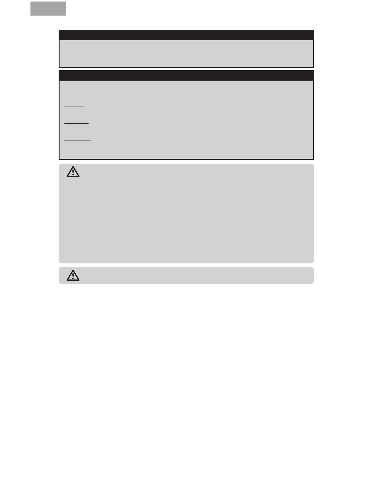
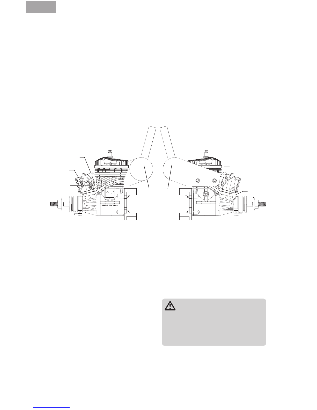
Muffler
Spark Plug
Fuel Nipple
High-Speed
Needle
Choke Arm
Low-Speed
Needle
Installing the Engine
Page 6
EN
6
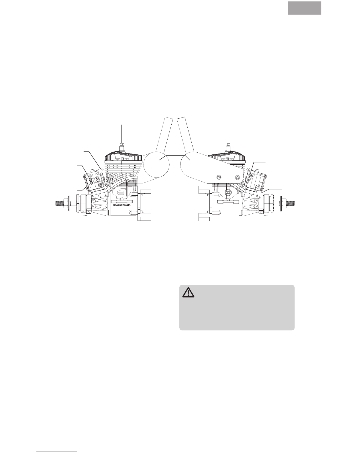
1. Use a secure method to attach the
throttle linkage to the throttle arm on the
carburetor.
2. Power on the transmitter and receiver.
3. Move the throttle stick to the middle stick
position.
4. Adjust the throttle arm so the arm is 90
degrees to the throttle pushrod.
5. With the throttle servo centered, install a
servo arm with a hole at least 15mm (5/8
in) from the center of the arm.
6. Use a clevis to attach the throttle linkage to
the servo arm.
15mm
Connecting the Throttle Linkage
1. Lower the throttle and center the throttle
trim.
2. Adjust the length of the throttle linkage
until the throttle is open 1mm.
3. Move the throttle stick up to conrm the
throttle opens. If the throttle does not
open, reverse the throttle channel in your
transmitter.
4. Move the throttle stick and throttle trim
down to confirm the throttle closes.
5. If you reversed the throttle channel in your
transmitter and you are using a 2.4GHz
radio system, you must re-bind your radio
system to set the correct failsafe position.
You may need to adjust the endpoints on your
radio to achieve full throttle motion. Using
a longer servo arm will help obtain the best
throttle geometry.
Adjusting the Throttle Opening
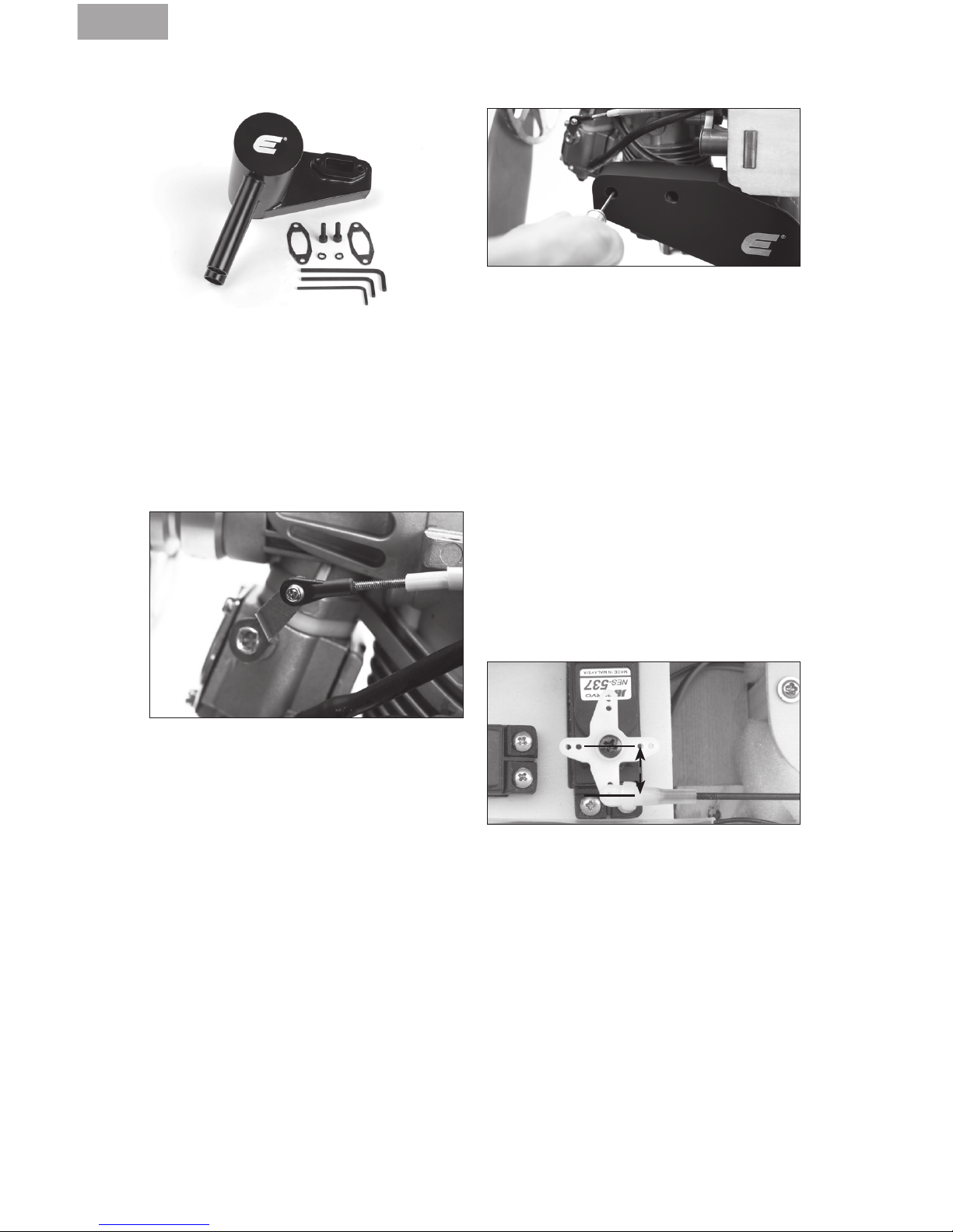
Installing the Muffler
The muffler mounting accessory package
includes mounting screws (2), lock washers
(2), muffler gaskets (2) and L- wrenches (2).
We suggest using high-temperature RTV as a
locking agent on the muffler screws to keep
them tight.
1. Put a lock washer on each of the muffler
screws. Push the muffler screws through
the muffler.
2. Place the muffler gasket over the muffler
mounting screws.
3. Align the mufer gasket with the exhaust
opening and the muffler mounting screws.
4. Tighten the muffler screws.
Page 7
EN
7
Fuel Line
1. Connect medium diameter large diameter
FKM fuel tubing to the carburetor and the
fuel tank supply line.
2. Connect large diameter FKM fuel line to the
vent line. Run this fuel line either around
the back of the tank or make a loop on top
of the tank to create an “anti-syphoning”
loop. Take the other end of the fuel line
and route it outside the airplane fuselage.
RECOMMENDED PROPELLERS
17 x 6–20 x 8 (18 x 8 has tested to be the
best performer with this engine, although
the performance is very good throughout the
recommended range)
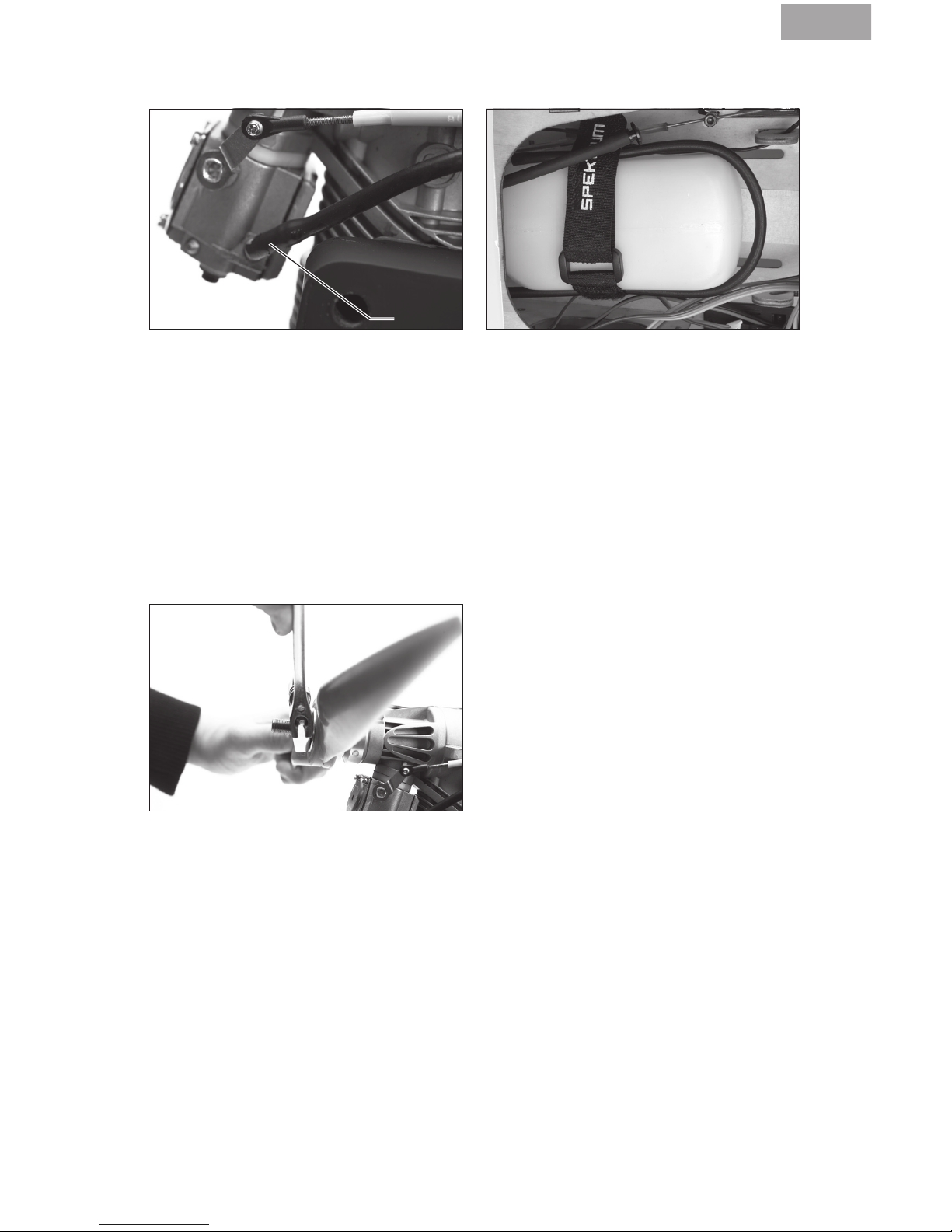
1. Remove the prop nut and prop washer from
the crankshaft.
2. Install the spinner backplate, followed by
the propeller, prop washer and prop nut.
3. Cover the propeller with a cloth and use an
adjustable wrench to tighten the prop nut.
4. Install the spinner cone. Make sure the
spinner cone is not touching the propeller.
Trim the propeller opening if necessary.
5. Tighten the spinner screw(s) to secure the
spinner cone.
Attaching the Propeller and Spinner
Attaching the Fuel Lines
Page 8

EN
8
Connecting the Electronic Ignition
The Evolution Electronic Ignition Assembly is designed and engineered specifically for the
small block engine series. It is smaller and lighter so it fits into tighter spaces of the airplanes
the engines are designed to power. The battery voltage required is between 4.8V (4-cell Ni-MH
pack) and 8.4V (2S Li-Po battery) and no voltage regulators are needed with any of these
batteries. We recommend a 2S Li-Fe battery (such as the Team Orion® Avionics Li-Fe Receiver
Pack 1300mAh 6.6V (ORI60503)) and we have done extensive testing with these packs. The
maximum amp draw at full throttle is 450mAh, and our more typical average has been between
250–300mAh.
The assembly consists of:
• Ignition module with battery connector, ignition sensor connector, tachometer readout
connector and spark plug connector
• Ignition sensor (already attached to your engine)
• Sensor magnet (already installed in the prop drive hub of your engine)
Mounting Your Electronic Ignition
• You can mount the unit in any orientation
and place that is convenient for your
installation. The module is sized to conveniently fit into the tank compartment of
most glow powered airplanes alongside or
underneath the recommended fuel tanks.
You can also mount it to the firewall or
under the engine firewall extension if your
airplane is so equipped. Keep in mind that
it should be mounted away from the heat of
the muffler.
• Secure the ignition module to your chosen
location with foam padding to provide
vibration isolation. We typically mount it
conveniently with tie wraps after wrapping
the ignition in lightweight 1/4-inch foam
rubber.
• You may need to route both the spark plug
connector wire and the ignition sensor wire
through the firewall, so be sure to plan
ahead and provide adequately sized holes
that will allow you to pull either the ignition
sensor connector or the spark plug cap
connector through the holes for later
ignition removal.
• Mount a good quality radio receiver type
switch between the ignition unit and the
battery. Mount this switch in a convenient
place on the outer fuselage close to the
front of the airplane to make it easy to turn
the ignition on and off. Being able to easily
shut off the ignition is an important safety
consideration.
• Connect the ignition sensor wire to the
ignition module. The sensor wire will only
fit into one of the connectors so you cannot
connect it wrong.
• Connect the ON/OFF switch to the battery
connector lead of the ignition module. This
connector is the red connector.
• For added security and controllability, add
an additional radio-operated kill switch
(such as the Optical Ignition Kill Switch
EVOA100) between the ignition battery con-
nector lead and the ON/OFF switch.
• If desired, you can connect either the
separately available tachometer readout or
the included Evolution/Spektrum Telemetry
Adapter Cable (EVOA107) to the tachometer
readout connector. Plug the other end of
the adapter cable into the Spektrum
telemetry module’s rpm input port.
• Connect the spark plug connector to the
spark plug. This spark plug connector
utilizes a locking snap ring to ensure a
solid connection. Push it straight onto the
spark plug to secure.
Make sure you charge your ignition battery.
You are now ready to operate your electronic
ignition with the engine.
Page 9

EN
9
Fuel
This engine requires a mix of 20:1 gas to oil
lubricant ratio for break-in and a mix of 32:1
gas/oil ratio for normal operation in order to
last a long time.
The needle bearing at the bottom end of the
conrod depends upon this lube ratio to operate properly.
Do not go higher than a 20:1 gas/oil ratio
for the first gallon of fuel. After this you may
decrease the oil content to a 32:1 gas/oil ratio
if desired. Do not go higher than a 32:1 gas/
oil ratio or the warranty on your engine will be
voided.
To properly mix the fuel, for a mix of 20:1 gas
to oil, add 6.75 oz of good quality 2-stroke
oil to one gallon (or 53 mL of oil to one liter)
of 87–93 octane fuel. (EVOX1001Q Evolution
2-stroke oil is recommended) We prefer to
add the oil first to our fuel container and to
add the gasoline second. This helps to ensure
a good mixture of the oil with the fuel at the
outset.
We have tested our own Evolution 2-stroke oil,
Valvoline, Shell, RedLine and Husqvarna oils.
Other quality 2-stroke oils should work as
well. Do not use Amsoil synthetic oil in
any form.
It is very important to properly construct
your fuel supply system to avoid operating
problems. Our experience has shown that
many seemingly engine related operating
problems are in fact fuel delivery problems,
not engine related problems.
Fuel Filtering - Because of the incredibly small
amount of fuel that is being used by this
engine, filtration of the fuel is mandatory in
three different spots in the system:
1. Between the fuel jug and the airplane fuel
tank.
2. Within the fuel tank itself (with a ltered
clunk EVOA112).
3. Between the fuel tank and carburetor (with
an in-line fuel lter EVOA111).
Both of these lters (2 and 3) are included in
the engine package.
Tank Choice and Construction – Choose a
tank between 12–18 oz (360–540 mL). These
tanks will yield 12 minutes (for the smaller
tank) to 18 minutes (for the larger tank) of full
throttle flying time.
• Ensure you use a tank stopper made for
use with gasoline and/or smoke oil.
• We suggest a three-line tank system; one
for the line to the carburetor with the clunk
attached internally, one for the vent line
from the tank, and one dedicated to fueling/defueling the tank. We try to avoid the
T-fittings and other inline valves because
they can be a possible source of air/fuel
leaks.
Filtered Weight
Gasoline-resistant
Rubber Cap
Fuel Tank
Vent Tube
Fueling Tube
Gasoline-resistant Tube
Gasoline-resistant Tube
Carb Nipple
Fuel Filter
• Ensure you use the provided FPM tubing in
all the plumbing of the tank, externally and
internally.
• Ensure you use the included felt lter clunk
inside the fuel tank.
• Ensure you use the included inline lter
between the tank and the carburetor.
• Ensure there is a good seal system for
the dedicated fueling/defueling line. We
highly recommend the HAN116 Fuel Filler
Assembly for its sleek look and ease of use
when installed on your airplane.
Fuel Delivery System
Page 10

EN
10
Engine Break-in
Your new engine needs to be broken-in to ensure a long life of all the components. This engine
features a piston ring design, which requires a specific break-in procedure to ensure a tight seal
between the piston ring and liner. For this to be accomplished, this process requires repeated
heating and cooling cycles, and must be done at a needle setting that is slightly rich of peak to
ensure the ring expands and contracts. The ring needs to “grow” into the liner for it to develop a
good seal.
Breaking in the piston ring and liner by running it too rich does not provide the necessary parts
growth to accomplish the needed piston ring and liner fitting. However, using too lean of a
setting will cause the ring to become damaged by overheating. Please follow the steps below to
ensure a successful experience.
Important considerations during break-in
• Perform the break-in process with the
engine mounted on your airplane. There is
no need to bench-run the engine prior to
mounting it on your airplane.
• Use the suggested break-in prop to begin
your break-in process. This provides a light
load and high rpm that, when matched
with the heat of the engine, will break in
the engine properly.
• Use the proper recommended fuel with a
20:1 gas to oil ratio for the rst gallon of
operation.
The proper break-in flight procedure is to fly
the airplane at full throttle through a series
of gure eight maneuvers (i.e. Cuban Eight).
These maneuvers in particular benefit the engine because, when climbing, the additional
load on the engine will increase the temperature and, when diving, the lighter load and
higher rpm will decrease the temperature,
thus providing the heating/cooling cycles
required for the break-in process.
Break-in process
• Firsttankoffuel: Set the high-speed
needle valve at 1.5 turns out and use the
suggested break-in prop. Run the engine
on the ground for its first tank of fuel and
DO NOT go above half throttle. Cycle the
throttle between idle and half throttle every
minute.
• Second tank of fuel: Tune the needle valve
to be slightly rich of the peak RPM at full
throttle without a drop in RPM. Do not run
at full throttle on the ground for more than
30 seconds at a time. Tune the low speed
needle valve for a smooth transition from
idle to mid-range, go back to full throttle
to confirm the main needle valve setting
and then fly. During this flight, be sure to
be conscientous of extended periods of
heating the engine. Be sure to mix-in some
cool-down dives and lower-throttle flying.
• Third tank of fuel: Fly the engine at a high
throttle while performing the recommended
figure eight maneuvers. This will help the
piston ring and cylinder liner to expand and
contract; helping the breaking-in process.
Tune the needle valve to be slightly rich of
the peak RPM as necessary.
• Fourth tank of fuel: Select one of the rec-
ommended propellers for normal operation
and mount it on your engine. Tune the main
needle valve to be slightly rich of the peak
RPM and the low speed needle valve for a
smooth transition from idle to full throttle
and continue to break-in the engine in
flight.
Do not worry about an engine setting being
slightly rich during this process. When set
correctly, the engine will occasionally sound
as if it is misring (which it is). During the
climbing maneuvers this should go away and
might return during the diving maneuvers. If
it does not go away during the climbs, land
the airplane and lean the high-speed needle
by 1/16 of a turn, then take off and y again.
Enjoy the break-in process—you are doing a
lot of flying.
Fly the airplane through the first gallon of fuel,
then you can change the fuel mixture to 32:1
for continued operation.
Page 11

EN
11
Baseline needle valve settings can be found
in the ”Engine Tuning” section. With the 33GX
it is very important to allow the temperature
to stabilize above 140°F (60°C) before making any adjustments; adjusting prior to the
engine warming up will lead you to inaccurate
settings. As the engine warms up you will
notice the rpms naturally rising.
If you do not have a temp gun or have sensors
installed on your engine, allow the engine to
run at half throttle for at least 45 seconds before attempting to set the high-speed needle.
If you have accurately set the low-speed
needle as described you should not need to
adjust it.
Priming
1. Make sure your ignition is off.
2. Open the throttle fully and, close the choke
valve. Flip the propeller 6 times.
3. Close the carburetor completely with your
throttle stick and then open it two detents
from closed. This will allow the engine to
start at a low throttle setting.
Because each fuel system and installation
is slightly different, you may find the need
to modify the above procedure for your
individual setup. The above procedure should
work for most installations.
Starting and Operating the 33GX Engine
Telemetry is a huge asset to help you tune
your engine. The ignition module is even
capable of communicating with Spektrum
telemetry systems directly so you won’t have
to add an additional RPM sensor. You will
need to connect the Evolution Ignition
Telemetry Adapter (EVOA107) between the
RPM port on the ignition unit and the RPM
port on your Spektrum telemetry module in
order to utilize this feature. Telemetry systems
other than Spektrum may require a dedicated
RPM sensor.
We recommend using the Spektrum DSMX Full
Range Aircraft Telemetry Module (SPM9548)
in conjunction with the included adapter. This
system allows you to see real-time RPM and
temperature readings from the engine.
The temperature sensor should be wrapped
around the base of the spark plug on the
cylinder head. Using telemetry gives you an
accurate representation of actual temperature
and rpm figures during use, and warnings
can be set to go off if your engine is getting
too hot.
The temperature range should be 190–240°F
(87–115°C) on average. Set your maximum
temperature warning to go off if the engine
exceeds 300°F (150°C). If your engine is continually near this peak temperature or higher,
immediately decrease throttle to bring the
temperature down. If this continues to occur,
land the airplane and add additional baffling
to your cowl. It is not good for the engine to
run at temperatures this high and could cause
damage if not attended to.
Telemetry
Page 12

EN
12
The break-in settings for the carburetor
needles are:
• High-speed needle: 1.5 turns open
• Low-speed needle: 1.5 turns open
Use a tachometer (HAN111, HAN156, or
telemetry) to tune the engine based on RPM.
To lean the high- or low-end fuel mixture, turn
the high- or low-speed needle clockwise. To
enrich the high- or low-end fuel mixture, turn
the high- or low-speed needle counterclockwise. It is best to make all the carb adjustments with the engine turned off.
WARNING: Always adjust the
carburetor from behind the
propeller. Keep all loose items
away from the propeller at all times.
Never reach over or around the
propeller.
1. Start the engine.
2. Move the throttle stick up until the engine
is running at approximately 2,000 rpm.
3. Move the throttle stick up to full (open)
throttle. If the engine runs rough, the fuel
mixture is too rich. If the engine stops running, it is too lean.
4. With the engine shut down, either enrich
or lean (as indicated by the test in Step 3)
the high-speed needle screw by 1/16th of a
turn and restart the engine. Turn the high-
speed needle clockwise 1/16 turn to lean
the high-end fuel mixture.
5. Repeat Steps 3–4 until the engine is
running reliably at full (open) throttle.
Engine Tuning
Until the engine is broken in, use an electric
starter to start the engine. Once it is fully
broken in it can be started by hand, but it is
easier and safer to start the engine with an
electric starter.
1. Turn on the ignition.
2. Close the choke valve.
3. If Using an Electric Starter
a. Rotate the propeller in a backwards
direction against compression.
b. Push the start firmly against the nose
cone and engage. The engine should fire
relatively quickly, within 1-2 seconds.
c. Turn off the choke and engage the starter
as before until the engine starts.
If Using a Starting Stick or Flipping by Hand
a. Rotate the propeller counter-clockwise
until against compression.
b. Flip the propeller through compression
until it fires.
c. Turn off the choke.
d. Flip the engine through compression as
before until it starts.
4. Let the engine run at mid-throttle for 45
seconds to stabilize the temperatures.
a. If the engine doesn’t start quickly, disen-
gage the starter. Continuously running
the starter can flood the engine.
b. Check to make that fuel is moving
through the carburetor system.
c. If the engine appears not to have any
fuel, repeat the priming procedure
above.
d. Repeat 1–4 of Starting and Running the
Engine.
Starting and Running the Engine
Page 13

EN
13
Once the engine is running reliably at full
(open) throttle:
1. Turn the high-speed needle clockwise 1/16
of a turn at a time.
2. Wait 2–3 seconds for the engine to
respond.
a. If there is an increase in RPM: Turn the
high-speed needle clockwise an
additional 1/16 turn and wait for the
engine to respond to the tuning change.
If there is no increase in RPM after the
change, turn the high-speed needle back
to its previous position.
b. If there is a decrease in RPM: Turn the
high-speed needle counterclockwise 1/8
of a turn and wait for the engine RPM to
stabilize.
3. Repeat Step 2 until you determine the
maximum RPM with the fuel and propeller
you selected.
4. Enrich the high-end fuel mixture by turning
the high-speed needle counterclockwise
until the RPM is 200–300 RPM below maximum. This will allow the engine to achieve
proper fuel mixture during flight.
High-Speed Needle Tuning
Low -Speed Needle Adjustment
The low-speed needle adjustment controls the fuel/air mixture at idle and the quality of the
transition between idle and wide open throttle.
Low -Speed Needle Tuning
1. Adjust the high-speed needle for the current conditions.
2. Allow the engine to idle for 10–15 seconds.
Rapidly advance the throttle from idle to
full open. If the engine transitions with
no hesitation, the low-speed needle is
adjusted perfectly. If the engine slowly
responds to throttle change and gradually
reaches peak RPM, the low-end fuel mixture is too rich. Turn the low-speed needle
clockwise 1/16 turn to lean out the low-end
fuel mixture and test again.
If the engine stops running, the low-end
fuel mixture is too lean. Enrich the low-end
fuel mixture by turning the low-speed
needle counterclockwise 1/16 turn and
test again.
3. When the low-speed needle adjustment
is correct, check the high-speed needle
setting again.
4. When you are satisfied with the needle
settings, you should not need to adjust the
mixture needles again.
The best indication that your engine is tuned
properly is the color of the spark plug when
you remove it from the cylinder. A nice, dry,
tan color is an indicator that the fuel mixture
is correct and burning well. Wet plugs or
carbon deposits generally indicate that the
engine is running too rich. If the spark plug
has a white or gray appearance, you are running your engine too lean.
Page 14
EN
14
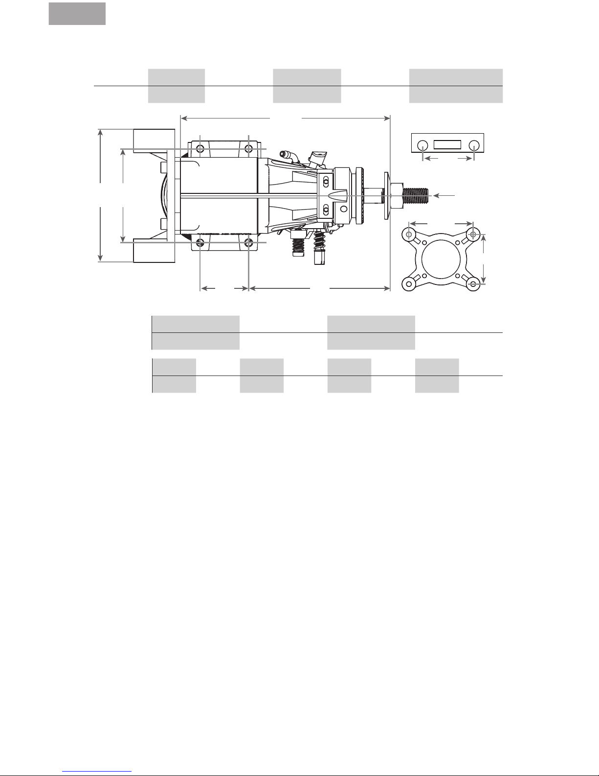
33GX Evolution Engines Specications
Disp Bore (mm) Stroke (mm) Weight (oz) Cylinder Propeller
33cc 37.5 29.5 48.8 Ringed 18 x 8 @ 8300 rpm
A
C D
F
H
G
70mm
54mm
B
E = height* F = length G= crankshaft thread size H = muffler bolt spacing
Weight (oz)
Engine Only Muffler Ignition Total
38.8 5.8 3.6 48.8
Dimensions
(mm)
A B C D E* F G H
50 60 31 73.3 104 121 3/8–24 36.5
* Height is from engine C/L to top of cylinder head.
Troubleshooting Guide
If the Engine Does Not Start
• Check and use a new spark plug if needed.
• Check fuel lines.
• Check for proper mechanical function by turning
the engine over.
• Check that the carburetor is correctly installed.
• Check that the vent line is attached and free
from any bends or blockages.
If the engine runs erratic
• Check for fuel systems problems. Are there any
holes in the fuel lines (inluding the clunk line
inside the fuel tank) or other possible sources
of air leaks, such as a loose fuel filter?
• Ensure the spark system is working
properly and the ignition battery is charged.
Mechanical Faults
If the engine cannot be turned over easily:
• The most likely cause is the engine is ooded
and by turning the engine over you are trying to
compress the fuel, not air.
1. Remove the spark plug.
2. Cover the cylinder head with a cloth or paper
towel and turn the propeller over to expel all
the excess fuel.
3. Replace the spark plug and try starting again.
• A possible cause is the piston in the cylinder is
seized: loosen and unscrew the cylinder head
bolts.
1. Carefully remove the cylinder liner.
2. Visually examine the piston and cylinder
to find the possible cause of the engine’s
mechanical problem.
Mechanical repairs must ALWAYS be completed by
an authorized Horizon Hobby service center.
Maintenance
After each flying session:
1. Fully drain the fuel from the tank.
2. Start the engine and run it until the fuel is
completely run out of the engine.
3. Try starting the engine three more times or until
it will no longer fire. This gets all the fuel out of
the engine.
If you need additional help or have any questions,
please call Horizon’s Support Team. Horizon has
trained technicians who are qualified to answer
your engine questions.
Page 15
EN
15
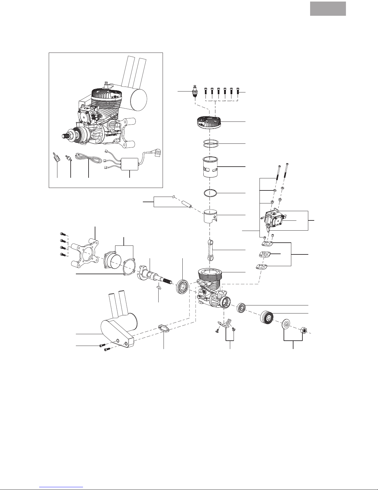
Exploded View
2
23 22 2024
1
3
4/29
5
6
7
8
31
26/29
12
11
102128/29/30
28
18
15
29
19
17
16 14
25
27
32
9
13
Page 16

EN
16
Parts List
# Description Part
1 Engine Crankcase
Screw Set (10)
EVOG3346408
2 Spark Plug (CM6) EVOG33350
3 Cylinder Head EVOG33103
4 Cylinder Head Gasket (2) EVOG33112
5 Cylinder EVOG33202
6 Piston Ring EVOG33236
7 Piston Set EVOG33214R
8 Piston Pin & Retainer EVOG33213
9 Connecting Rod EVOG33204
10 Prop Washer & Nut EVO108228
11 Drive Hub EVOG33219
12 Front Bearing EVO180109
13 Crankcase EVOG33101
14 Rear Bearing EVOG33110
15 Key EVO400218
16 Crankshaft EVOG33210
17 Back Cover Set EVOG33102
18 Wraparound In-Cowl
Muffler Assembly
EVOG33601
19 Rear Engine Mount EVOG33147
# Description Part
20 Complete Ignition
System
EVOG33300
21 Ignition Sensor &
Mount Bracket
EVOG33310A
22 In Line Fuel Filter EVOA105
23 In Tank Fuel Filter/Clunk EVOA106
24 Medium Gas-FPM Fuel
Tubing
EVOA102
25 Carburetor Assembly EVOG33801
26 Carburetor Mount
Gasket Set
EVOG33804
27 Carburetor Insulator EVOG33803
28 Muffler Mounting
Screw Set
EVOG33100A
29 Gasket Set EVOG33416
30 Mufer Gasket Set (2) EVOG33609
31 Carb Mount Bolt Set EVOG33119
32 Throttle & Choke Arm EVOGG33864
NS Carburetor Rebuild Kit EVOG33108A
NS Carburetor Gasket Set EVOG33109A
NS High-Speed/Low-
Speed Needle Set
EVOG33829
2-YEAR LIMITED WARRANTY
What this Warranty Covers - Horizon Hobby, Inc.,
(Horizon) warrants to the original purchaser that
the product purchased (the “Product”) will be free
from defects in materials and workmanship for a
period of 2 years from the date of purchase.
What is Not Covered - This warranty is not trans-
ferable and does not cover (i) cosmetic damage, (ii) damage due to acts of God, accident,
misuse, abuse, negligence, commercial use,
or due to improper use, installation, operation
or maintenance, (iii) modication of or to any
part of the Product, (iv) attempted service by
anyone other than a Horizon Hobby authorized
service center, (v) Product not purchased from
an authorized Horizon dealer, or (vi) Product not
compliant with applicable technical regulations.
OTHER THAN THE EXPRESS WARRANTY ABOVE,
HORIZON MAKES NO OTHER WARRANTY OR REPRESENTATION, AND HEREBY DISCLAIMS ANY AND
ALL IMPLIED WARRANTIES, INCLUDING, WITHOUT
LIMITATION, THE IMPLIED WARRANTIES OF NONINFRINGEMENT, MERCHANTABILITY AND FITNESS
FOR A PARTICULAR PURPOSE. THE PURCHASER
ACKNOWLEDGES THAT THEY ALONE HAVE DETERMINED THAT THE PRODUCT WILL SUITABLY MEET
THE REQUIREMENTS OF THE PURCHASER’S IN-
TENDED USE.
Purchaser’s Remedy - Horizon’s sole obligation
and purchaser’s sole and exclusive remedy shall
be that Horizon will, at its option, either (i) service,
or (ii) replace, any Product determined by Horizon
to be defective. Horizon reserves the right to in-
spect any and all Product(s) involved in a warranty
claim. Service or replacement decisions are at
the sole discretion of Horizon. Proof of purchase
is required for all warranty claims. SERVICE OR
REPLACEMENT AS PROVIDED UNDER THIS WARRANTY IS THE PURCHASER’S SOLE AND EXCLUSIVE
REMEDY.
Page 17

EN
17
Limitation of Liability - HORIZON SHALL NOT BE
LIABLE FOR SPECIAL, INDIRECT, INCIDENTAL OR
CONSEQUENTIAL DAMAGES, LOSS OF PROFITS OR
PRODUCTION OR COMMERCIAL LOSS IN ANY WAY,
REGARDLESS OF WHETHER SUCH CLAIM IS BASED
IN CONTRACT, WARRANTY, TORT, NEGLIGENCE,
STRICT LIABILITY OR ANY OTHER THEORY OF LIABILITY, EVEN IF HORIZON HAS BEEN ADVISED OF
THE POSSIBILITY OF SUCH DAMAGES. Further, in
no event shall the liability of Horizon exceed the
individual price of the Product on which liability
is asserted. As Horizon has no control over use,
setup, final assembly, modification or misuse, no
liability shall be assumed nor accepted for any re-
sulting damage or injury. By the act of use, setup
or assembly, the user accepts all resulting liability.
If you as the purchaser or user are not prepared to
accept the liability associated with the use of the
Product, purchaser is advised to return the Product immediately in new and unused condition to
the place of purchase.
Law - These terms are governed by Illinois law
(without regard to conict of law principals). This
warranty gives you specific legal rights, and you
may also have other rights which vary from state
to state. Horizon reserves the right to change or
modify this warranty at any time without notice.
WARRANTY SERVICES
Questions, Assistance, and Services - Your local
hobby store and/or place of purchase cannot provide warranty support or service. Once assembly,
setup or use of the Product has been started, you
must contact your local distributor or Horizon directly. This will enable Horizon to better answer
your questions and service you in the event that
you may need any assistance. For questions or
assistance, please visit our website at www.horizonhobby.com, submit a Product Support Inquiry,
or call the toll free telephone number referenced
in the Warranty and Service Contact Information
section to speak with a Product Support representative.
Inspection or Services - If this Product needs to
be inspected or serviced and is compliant in the
country you live and use the Product in, please
use the Horizon Online Service Request submission process found on our website or call Horizon
to obtain a Return Merchandise Authorization
(RMA) number. Pack the Product securely using
a shipping carton. Please note that original boxes
may be included, but are not designed to withstand the rigors of shipping without additional
protection. Ship via a carrier that provides tracking and insurance for lost or damaged parcels, as
Horizon is not responsible for merchandise until
it arrives and is accepted at our facility. An Online
Service Request is available at http://www.horizonhobby.com/content/_service-center_renderservice-center. If you do not have internet access,
please contact Horizon Product Support to obtain
a RMA number along with instructions for submitting your product for service. When calling Horizon, you will be asked to provide your complete
name, street address, email address and phone
number where you can be reached during business hours. When sending product into Horizon,
please include your RMA number, a list of the
included items, and a brief summary of the problem. A copy of your original sales receipt must be
included for warranty consideration. Be sure your
name, address, and RMA number are clearly written on the outside of the shipping carton.
NOTICE: Do not ship LiPo batteries to Horizon. If
you have any issue with a LiPo battery, please
contact the appropriate Horizon Product Support
office.
Warranty Requirements - For Warranty consideration, you must include your original sales receipt
verifying the proof-of-purchase date. Provided
warranty conditions have been met, your Product
will be serviced or replaced free of charge. Service
or replacement decisions are at the sole discretion
of Horizon.
Non-Warranty Service - Should your service not
be covered by warranty, service will be completed
and payment will be required without notification
or estimate of the expense unless the expense
exceeds 50% of the retail purchase cost. By sub-
mitting the item for service you are agreeing to
payment of the service without notification. Service estimates are available upon request. You
must include this request with your item submitted for service. Non-warranty service estimates
will be billed a minimum of ½ hour of labor. In addition you will be billed for return freight. Horizon
accepts money orders and cashier’s checks, as
well as Visa, MasterCard, American Express, and
Discover cards. By submitting any item to Horizon
for service, you are agreeing to Horizon’s Terms
and Conditions found on our website http://www.
horizonhobby.com/content/_service-center_render-service-center.
ATTENTION: Horizon service is limited to Product
compliant in the country of use and ownership.
If received, a non-compliant Product will not be
serviced. Further, the sender will be responsible
for arranging return shipment of the un-serviced
Product, through a carrier of the sender’s choice
and at the sender’s expense. Horizon will hold
non-compliant Product for a period of 60 days
from notification, after which it will be discarded.
Page 18
EN
18
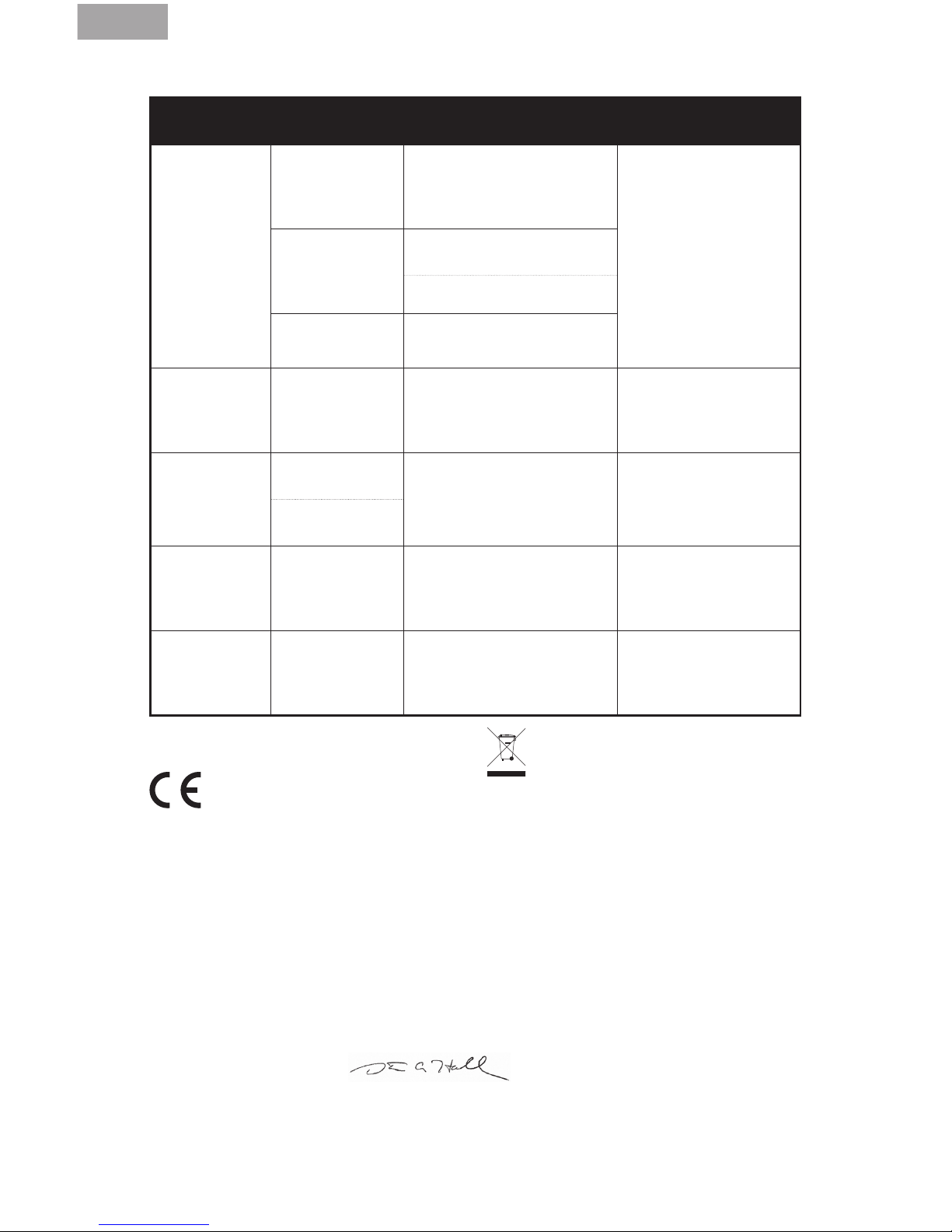
WARRANTY AND SERVICE CONTACT INFORMATION
Country of
Purchase
Horizon Hobby Contact Information Address
United States of
America
Horizon Service
Center
(Repairs and
Repair Requests)
servicecenter.horizonhobby.
com/RequestForm/
4105 Fieldstone Rd
Champaign, Illinois,
61822 USA
Horizon Product
Support
(Product Technical
Assistance)
www.quickbase.com/db/
bghj7ey8c?a=GenNewRecord
888-959-2305
Sales
sales@horizonhobby.com
888-959-2305
United Kingdom
Service/Parts/
Sales:
Horizon Hobby
Limited
sales@horizonhobby.co.uk Units 1–4 , Ployters Rd,
Staple Tye
Harlow, Essex, CM18 7NS,
United Kingdom
+44 (0) 1279 641 097
Germany
Horizon Tech-
nischer Service
service@horizonhobby.de
Christian-Junge-Straße 1
25337 Elmshorn, Germany
Sales: Horizon
Hobby GmbH
+49 (0) 4121 2655 100
France
Service/Parts/
Sales:
Horizon Hobby
SAS
infofrance@horizonhobby.com
11 Rue Georges Charpak
77127 Lieusaint, France
+33 (0) 1 60 18 34 90
China
Service/Parts/
Sales:
Horizon Hobby –
China
info@horizonhobby.com.cn
Room 506, No. 97 Chang-
shou Rd.
Shanghai, China 200060
+86 (021) 5180 9868
COMPLIANCE INFORMATION FOR
THE EUROPEAN UNION
Declaration of Conformity
(in accordance with ISO/IEC 17050-1)
No. HH2013032705
Product(s): EVO 33cc Gas Engine
Item Number(s): EVOE33GX
The object of declaration described above is in
conformity with the requirements of the
specifications listed below, following the provi-
sions of the European EMC Directive 2004/108/
EC:
EN55022:2010 + AC:2011
EN55024:2010
Signed for and on behalf of:
Horizon Hobby, Inc.
Champaign, IL USA
March 27, 2013
Instructions for disposal of WEEE by
users in the European Union
This product must not be disposed of
with other waste. Instead, it is the user’s responsibility to dispose of their waste equipment by
handing it over to a designated collections point
for the recycling of waste electrical and electronic equipment. The separate collection and
recycling of your waste equipment at the time of
disposal will help to conserve natural resources
and ensure that it is recycled in a manner that
protects human health and the environment.
For more information about where you can drop
off your waste equipment for recycling, please
contact your local city office, your household
waste disposal service or where you purchased
the product.
Steven A. Hall
Executive Vice President and Chief Operating Ofcer
International Operations and Risk Management
Horizon Hobby, Inc.
Page 19
DE
19
WARNUNG: Lesen Sie die GESAMTE Bedienungsanleitung, um sich vor dem Betrieb
mit den Produktfunktionen vertraut zu machen. Wird das Produkt nicht korrekt
betrieben, kann dies zu Schäden am Produkt oder persönlichem Eigentum führen
oder schwere Verletzungen verursachen.
Dies ist ein hochentwickeltes Hobby-Produkt. Es muss mit Vorsicht und gesundem Menschenverstand betrieben werden und benötigt gewisse mechanische Grundfähigkeiten. Wird
dieses Produkt nicht auf eine sichere und verantwortungsvolle Weise betrieben, kann dies
zu Verletzungen oder Schäden am Produkt oder anderen Sachwerten führen. Dieses Produkt
eignet sich nicht für die Verwendung durch Kinder ohne direkte Überwachung eines Erwachsenen. Versuchen Sie nicht ohne Genehmigung durch Horizon Hobby, Inc., das Produkt
zu zerlegen, es mit inkompatiblen Komponenten zu verwenden oder auf jegliche Weise zu
erweitern. Diese Bedienungsanleitung enthält Anweisungen für Sicherheit, Betrieb und
Wartung. Es ist unbedingt notwendig, vor Zusammenbau, Einrichtung oder Verwendung alle
Anweisungen und Warnhinweise im Handbuch zu lesen und zu befolgen, damit es bestimmungsgemäß betrieben werden kann und Schäden oder schwere Verletzungen vermieden
werden.
ACHTUNG: Dieses Produkt kann bei dem Betrieb extrem heiß werden was zu
Verbrennungen führen kann.
Nicht geeignet für Kinder unter 14 Jahren. Dies ist kein Spielzeug.
Sicherheitswarnungen
Modellmotoren haben eine erhebliche Leistung, die bei unsachgemäßer Verwendung eine Gefährdung darstellen kann. Nutzen Sie bei dem Betrieb immer den gesunden Menschenverstand
und beachten alle Sicherheitshinweise bei dem Umgang mit dem Motor, oder allen Tätigkeiten
in diesem Zusammenhang. Das nicht befolgen der Sicherheitsbestimmungen kann zu ernsthaften Personen- und Sachbeschädigungen führen.
• Stellen Sie immer sicher dass Zuschauer, insbesondere Kinder, mindestens 9,90 Meter
entfernt sind wenn Sie den Motor laufen lassen.
• Stellen Sie vor JEDEM Flug sicher, dass der Propeller fest mit der Kurbelwelle verbunden ist
und alle Halter/Befestigungen sicher angezogen/befestigt sind. Verwenden Sie zum sichern
von Schrauben und Muttern blauen Schraubensicherungslack.
• Halten Sie Kleinteile immer aus der Reichweite von Kindern, da diese verschluckt
werden können.
• Sichern Sie immer das Flugzeug bevor Sie den Motor starten.
• Halten Sie immer das Gesicht und den Körper weg vom Propellerkreis wenn Sie den Motor
starten oder wenn er läuft.
HINWEIS
Alle Anweisungen, Garantien und anderen zugehörigen Dokumente können im eigenen Ermessen von Horizon Hobby, Inc. jederzeit geändert werden. Die aktuelle Produktliteratur finden Sie
auf horizonhobby.com unter der Registerkarte „Support“ für das betreffende Produkt.
Die folgenden Begriffe werden in der gesamten Produktliteratur verwendet, um auf unterschiedlich hohe Gefahrenrisiken beim Betrieb dieses Produkts hinzuweisen:
HINWEIS: Wenn diese Verfahren nicht korrekt befolgt werden, können sich möglicherweise
Sachschäden UND geringe oder keine Gefahr von Verletzungen ergeben.
ACHTUNG: Wenn diese Verfahren nicht korrekt befolgt werden, ergeben sich wahrscheinlich
Sachschäden UND die Gefahr von schweren Verletzungen.
WARNUNG: Verfahren können bei nicht ordnungsgemäßer Durchführung möglicherweise
Schäden an Eigentum, Kollateralschäden UND schwere Verletzungen bis zum Tot ODER
höchstwahrscheinlich oberflächliche Verletzungen verursachen.
Spezielle Bedeutungen
Page 20

DE
20
• Stellen Sie sich immer hinter den Propeller wenn Sie Einstellungen am Vergaser vornehmen.
• Tragen Sie immer eine Schutzbrille beim Starten oder Laufen lassen des Motors.
• Bewahren Sie ihren Kraftstoff immer an einem sicheren Ort weit weg von möglicher
Funkenbildung, Hitze oder zündfähigen Stoffen auf.
• Stellen Sie immer sicher, dass das Luftfahrzeug korrekt gesichert ist und sich bei Motorstart
nicht bewegen/anrollen kann.
• Führen Sie nach den Einstellungen vor dem Erstug den Bindevorgang erneut aus.
• Stellen Sie immer sicher dass die Failsafeeinstellung des Gaskanal auf Motor aus/
Leerlauf steht.
• Führen Sie immer vor dem Flug einen Reichweitentest durch.
• Unterbrechen Sie die Kraftstoffversorgung (durch trennen oder abdrücken der
Kraftstoffleitung) oder schließen Sie mit Gasgestänge die Vergaserdrosselklappe
um den Motor zu stoppen.
• Gebrauchen Sie niemals Ihre Hände, Finger oder andere Körperteile um den Propeller
zu stoppen.
• Werfen Sie niemals etwas in den Propeller um ihn zu stoppen.
• Lassen Sie niemals den Motor über losen Untergrund wie Sand oder Kies laufen, damit
nicht die Gefahr besteht dass der Motor kleine Teile unkontrolliert hochschleudert.
• Tragen Sie niemals bei dem Betrieb des Modells lose Kleidung oder ein loses Nackenband/
Umhängegurt, da sich diese Teile im Propeller verfangen können.
• Führen Sie niemals bei Betrieb oder Umgang mit dem Motor lose Gegenstände wie
Schraubendreher, Stifte, etc.. in Ihren Taschen. Diese könnten in den Propeller fallen.
• Lassen Sie niemals Kraftstoff in Berührung mit Mund oder Augen kommen da dieser giftig ist.
• Lagern Sie Kraftsoff in eindeutig bezeichneten Behältnissen ausserhalb der Reichweite
von Kindern.
Sicherheitsrichtlinien
• Montieren Sie den Motor korrekt auf einer geeigneten Werkbank oder einem qualitativ
hochwertigen Motorträger.
• Verwenden Sie immer Propeller mit der richtigen Größe und Steigung. Sehen Sie dazu
in die Propellerliste in dieser Anleitung.
• Überprüfen Sie immer vor der Montage des Propellers dass dieser einwandfrei gewuchtet ist.
Das nichtbeachten könnte zu Motorschäden oder zu Schäden am Flugzeug führen.
• Verwenden Sie immer falls möglich einen Elektrostarter.
• Verwenden Sie keine Propeller die Knicke, Risse, Brüche oder sonstige Beschädigungen
aufweisen.
• Lassen Sie den Motor nur in gut belüfteten Bereichen laufen. Modellmotoren produzieren
giftige Kohlenmonoxid Abgase.
• Lagern Sie Kraftstoff nur in kühlen trockenen Orten. Lassen Sie Kraftstoffbehälter nicht in direkten Kontakt mit Beton kommen, da der Kraftstoff dadurch Feuchtigkeit aufnehmen könnte.
• Entsorgen Sie immer verantwortungsvoll Kraftstoff der durch Kondensation Feuchtigkeit (Was-
ser) aufgenommen hat.
• Schütten Sie niemals ungebrauchten Kraftstoff aus dem Tank in den Kanister.
• Modizieren, verändern und reparieren Sie niemals Propeller.
• Hantieren Sie nicht mit Modellmotoren, Schalldämpfern, Auspuffen oder Resorohren
bis diese vollständig abgekühlt sind. Diese können bei Betrieb extrem heiß werden.
Page 21

DE
21
Einleitung
Wir beglückwünschen Sie zum Kauf von einem der aufregend neuen Motoren aus der Evolution
Benzinmotoren Serie. Diese Motoren wurde von Grund auf neu entwickelt und ausgiebig getestet,
um einen zuverlässigen und problemlosen Betrieb mit der Sicherheit einer 2 Jahres Garantie zu
bieten. Dieses Handbuch führt Sie, wenn Sie es lesen und befolgen, durch einfache Schritte zu
einer erfolgreichen Anwendung. Herzlich willkommen bei der Evolution-Produktfamilie.
33cc Gas Engine Design
Basierend auf den weltweit tausenfach zuverlässig erprobten Nitromotoren haben wir für Sie
Benzinmotoren entwickelt, die Sie in in der Ausstattung, Leistung und den niedrigen Betriebskosten begeistern werden.
Schritt 1 Von Grund auf neu entwickelt wurde dieser Motor als leistungsstarker Antrieb für
20–30cc Aerobatic Flugzeuge. Wichtige Punkte in der Entwicklung waren eine einfache
Bedienung und hohe Zuverlässigkeit die für eine exzellente Leistung stehen.
Schritt 2 Das bekannte Walbro Vergasersystem sorgt mit Choke und Gashebel für ein problemlo-
ses Einstellen und Handling.
Schritt 3 Entwickel ein Schalldämpfersystem mit angepaßten Volumen und Ausrichtung, dass
einen perfekten Einbau und Dämpferausrichtung erlaubt und dazu für effektive Geräuschdämpfung sorgt.
Schritt 4 Entwickel sinnvolles Zubehör dass es Einsteiger bei Benzinmotoren leichter macht.
• Da die Menge des verbrauchten Kraftstoffs nur etwa ein Drittel der eines vergleichbaren Glühkerzenmotors ist, sind Konstruktion und Zuverlässigkeit des
Kraftstoffversorgungssystems zum Vergaser dreimal so kritisch. Mikroskopisch
kleine Schmutzteilchen, die problemlos durch die größeren Querschnitte eines
Glühkerzenmotor-Vergasers fließen, richten in einem Benzinsystem verheerende Schäden an. Dieses Schmutzproblem lösen wir durch einen Qualitäts-
Leitungslter wie z. B. unseren Leitungslter (EVOA105). Unser Motor ist mit
diesem Filter ausgerüstet.
• Das Gleiche gilt für Luftblasen aus dem Tank oder für kleine Lecks in der Ben-
zinleitung; was problemlos durch einen Glühkerzenmotor-Vergaser geht, wird
in einem Benzinsystem nicht toleriert, da die Luftblasen dreimal soviel Wirkung
zeigen wie vorher. Wir haben einen exzellenten Filzlterklotz entwickelt und
verbaut, der Luftblasenbildung in der Benzinleitungen verhindert. Dieser Filzk-
lotz ist für einen zuverlässigen und erfolgreichen Betrieb äußerst wichtig. Unser
Motor ist mit diesem Filter ausgerüstet.
• Wir haben herausgefunden, dass hohe Schalldämpfertemperaturen die normalen Tygonleitungen (die erste Wahl für Benzinmotoren) innerhalb von Mi-
nuten zerstören würde. Wir haben festgestellt, dass Neoprenschlauch zwar
den Temperaturen standhält aber dazu tendiert schnell zu verschleissen. Wir
haben einen Flouelastometerschlauch (FKM) Schlauch gewählt, der nicht nur
den Temperaturen standhält sondern eine weit höhere Haltbarkeit als Tygon
oder Neopren besitzt. Ein weiterer Vorteil dieser Leitungen besteht darin, dass
sie ohne zusätzliche Drähte oder Schlauchschellen gut an den Benzinleitungsanschlüssen halten. Ihr Motor ist mit einem Satz dieser Leitungen ausgerüstet.
Page 22
DE
22
Gasarm
Montage auf Motorträger
1. Entfernen Sie die vier Schrauben die den
Heckhalter halten.
2. Nehmen Sie den Heckhalter ab und
ersetzen die vier Schrauben mit den
kürzeren M3 Schrauben aus dem
Lieferumfang des Motors.
3. Schrauben Sie den Motorhalter an den
Motorträger und schrauben den Träger an
den Motorspant.
4. Schrauben Sie den Motor im Motorträger
fest wie in der Anleitung des Flugzeuges
beschrieben.
Heckmontage
1. Schrauben Sie den Motor mit M5 oder
10–32 Schrauben an den Motorspant.
Verwenden Sie Distanzstücke um den
korrekten Abstand des Propellers zum
Motorspant wie in der Anleitung
beschrieben einzustellen.
WARNUNG: Ziehen Sie vor jedem Flug
alle Motorbefestigungsschrauben
nach. Wenn Sie die
Motorbefestigungsschrauben nicht
nachziehen, können sie sich durch die
Vibrationen lockern und der Motor
kann sich vom Rumpösen.
Mitgelieferter Inhalt
MOTOR
• Schalldämpfer (EVOG33601)
• Schalldämpferschrauben, -dichtung
(EVOG33100A)
• Zündkerze (EVOG33350)
• Evolution/Spektrum Telemetrie-RPMAdapterkabel (EVOA107)
• Grosser FLM Kraftstsoffschlauch (EVOA109)
• Grosser Inline Kraftstofflter (EVOA111)
• Grosser Inline-Tanklter (Pendel) (EVOA112)
OPTIONALE ARTIKEL
• Drehzahlmesser (HAN156)
• Propeller 17 x 8 (APC17080) für das
Einlaufen; 18 x 8 (APC18080) für Normalug
• Optischer Zünd/Killschalter (EVOA100)
• Evolution Synthetic 2 Takt Öl (EVOX1001Q)
• Ultra Kraftstoff Pumpe (HAN155)
Schalldämpfer
Zündkerze
Kraftstoffnippel
Nadel für hohe
Drehzahl
Choke Hebel
Nadel für
niedrige
Drehzahl
Einbau des Motors
Page 23

DE
23
1. Verwenden Sie zum Anbringen des
Gasgestänges an den Gasarm des
Vergasers eine sichere Methode.
2. Schalten Sie den Sender und den
Empfänger ein.
3. Bewegen Sie den Gashebel auf die mittlere
Hebelstellung.
4. Stellen Sie den Gasarm so ein, dass er
einen Winkel von 90 Grad zum zur
Gasschubstange bildet.
5. Setzten Sie mit zentrierten Servo den Arm
auf mit einem Loch mindestens 15mm von
der Mitte entfernt.
6. Verwenden Sie einen Gabelkopf zum
Anbringen des Gasgestänges an den
Servoarm.
15mm
Verbindung des Gasgestänges
1. Senken Sie den Gashebel und zentrieren
Sie die Gastrimmung.
2. Stellen Sie die Länge des Gasgestänges so
ein, dass der Vergaserschieber 1 mm geöffnet ist.
3. Bewegen Sie den Gashebel nach oben, um
festzustellen, ob der Vergaserschieber sich
öffnet. Wenn der Vergaserschieber sich
nicht öffnet, invertieren Sie den Gaskanal
in Ihrem Sender.
4. Bewegen Sie den Gashebel und die
Gastrimmung nach unten, um festzustellen,
ob der Vergaserschieber sich schließt.
5. Wenn Sie den Gaskanal in Ihrem Sender
invertiert haben und ein Funksystem mit
2,4GHz verwenden, müssen Sie es neu
anbinden, um die richtige Failsafe-Position
einzustellen.
Möglicherweise müssen Sie die Endpunkte
in ihrer Fernsteueranlage einstellen um den
vollen Gasweg zu erreichen.
Einstellung des Vergaserschiebers
Einbau des Schalldämpfers
Das Schalldämpfer-Montagevorbereitung
umfasst Montageschrauben (2), Sicherungsscheiben (2), Schalldämpferdichtungen (2) und
Inbusschüssel (2).
Wir empfehlen die Verwendung eines
hochtemperatur- geeignetem
Schraubensicherungslackes (RTV), damit sich die
Schalldämpferschrauben nicht lösen können.
1. Setzen Sie einen Federring auf jede
Schalldämpferschraube und führen diese
durch den Dämpfer.
2. Setzen Sie die Dämpferdichtung über die
Schrauben.
3. Richten Sie die Schalldämpferdichtung zur
Auspufföffnung und den Schalldämpfermontageschrauben aus.
4. Ziehen Sie die Schalldämpferschrauben fest.
Page 24

DE
24
Kraftstoffleitung
1. Schließen Sie den FKM Kraftstoffschlauch
mit mittlerem Durchmesser an den
Vergaser und Tank an.
2. Schließen Sie den FKM Kraftstoffschlauch
mit dem großem Durchmesser an die
Belüftungsleitung an. Führen Sie diese
Leitung hinter den Tank oder machen eine
Schlaufe auf dem Tank um einen "Anti Sy-
phon" herzustellen. Führen Sie das andere
Ende der Kraftstofeitung das Rumpnnere.
EMPFOHLENE PROPELLER
17 x 6–20 x 8 (18 x 8 wurde als der
Propeller mit der für diesen Motor besten
Leistung getestet; die Leistung ist jedoch über
den gesamten empfohlenen Bereich sehr gut)
1. Entfernen Sie die Propellermutter und die
Propellerscheibe von der Kurbelwelle.
2. Montieren Sie die Spinner-Grundplatte,
dann den Propeller, die Propellerscheibe
und die Propellermutter.
3. Decken Sie den Propeller mit einem Tuch
ab und ziehen Sie die Propellermutter mit
einem verstellbaren Schraubenschlüssel
fest.
4. Montieren Sie den Spinnerkonus. Der
Spinnerkonus darf den Propeller nicht
berühren. Stellen Sie, falls erforderlich, die
Propelleröffnung ein.
5. Ziehen Sie die Spinnerschraube(n) fest, um
den Spinnerkonus zu sichern.
Anbringen von Propeller und Spinner
Anbringen der Kraftstoffleitungen
Page 25

DE
25
Anschließen der elektronischen Zündung
Die elektronische Zündung von Evolution wurde speziell für die Small Block-Motorreihe
konstruiert und gebaut. Sie ist kleiner und leichter und passt daher in kleinere Einbauräume
der Flugzeuge, welche die Motoren antreiben sollen. Die erforderliche Batteriespannung liegt
zwischen 4,8 V (Ni-MH-Pack mit 4 Zellen) und 8,4 V (2S Li-Po-Batterie); für keine dieser Batterien
sind Spannungsregler erforderlich. Wir empfehlen eine 2S Li-Fe-Batterie (wie z. B. die Team
Orion Avionics Li-Fe Receiver Pack 1300 mAh 6,6 V (ORI60503)); mit diesen Packs haben wir
umfangreiche Versuche durchgeführt. Die maximale Stromabgabe bei Vollgas beträgt 450 mAh,
die typische Durchschnittsabgabe liegt zwischen 250 und 300 mAh.
Die Baugruppe besteht aus:
• Zündmodul mit Batterieanschluss, Zündsensoranschluss, Drehzahlmesseranschluss und
Zündkerzenstecker.
• Zündsensor (bereits an Ihrem Motor angebaut)
• Sensormagnet (bereits in der Propeller-Antriebsnabe Ihres Motors eingebaut)
Montage Ihrer elektronischen Zündung
• Sie können das Zündmodul in jeder Lage und
an jeden Ort bauen, der für Ihre Installation
geeignet ist. Das Zündmodul kann dank seiner
geringen Abmessungen bequem an der Seite
des Tanks oder darunter montiert werden. Sie
können sie auch an das Brandschott oder
unter die Motorschottverlängerung bauen,
wenn Ihr Flugzeug so ausgestattet ist.
Beachten Sie, dass die Zündanlage aus
Hitzeschutzgründen nicht in die Nähe des
Schalldämpfers montiert werden darf.
• Sichern Sie das Zündmodul an dem von Ihnen
gewählten Montageort mit
Schaumstoffpolsterung, um Vibrationsschutz
zu schaffen. Wir befestigen das Zündmodul
normalerweise mit Kabelbindern, nachdem wir
es in leichtes, 6,35mm dickes Schaumgummi
eingewickelt haben.
• Möglicherweise müssen Sie sowohl das
Zündkerzenkabel als auch das
Zündsensorkabel durch das Brandschott
verlegen; darum planen Sie gut voraus und
bohren Sie Löcher ausreichender Größe,
damit Sie den Zündsensoranschluss bzw.
den Zündkerzenstecker durch die Bohrungen
bekommen, wenn Sie das Zündmodul später
einmal ausbauen wollen.
• Montieren Sie einen Radioempfängerschalter
hoher Qualität zwischen das Zündmodul und
die Batterie. Montieren Sie diesen Schalter
an einen gut zugänglichen Ort vorn an den
Außenrumpf, um das Zündmodul einfach
ein- und ausschalten zu können. Die Zündung
schnell ausschalten zu können, ist
sicherheitsrelevant.
• Für zusätzliche Sicherheit und Kontrolle
schließen Sie einen RC- Killschalter (wie
der optionale Zünd/Killschalter EVOA100)
zwischen dem Zündakkuanschluss und
dem EIN/AUS Schalter an.
• Schließen Sie das Zündsensorkabel an das
Zündmodul an. Das Sensorkabel passt nur
auf einen der Anschlüsse; ein
Falschanschluss ist nicht möglich.
• Schließen Sie den EIN-/AUS-Schalter an
das Batterieanschlusskabel des
Zündmoduls an. Dieser Anschluss ist rot.
• Falls gewünscht, können Sie entweder den
separat erhältlichen
Drehzahlmesserausgang oder das im
Lieferumfang enthaltene Evolution/
Spektrum Telemetrie-Adapterkabel
(EVOA107) an den Drehzahlmesser-
Ausgangsanschluss anschließen. Stecken
Sie das andere Ende des Adapterkabel in
den RPM Anschluß des Telemetriemoduls.
• Stecken Sie den Zündkerzenstecker auf
die Zündkerze auf. Der Glühkerzenadapter
ist mit einem Sicherungsring versehen
der eine feste Verbindung gewährleistet.
Drücken Sie ihn fest auf die Glühkerze um
eine festen Sitz zu gewährleisten.
Laden Sie Ihre Zündbatterie auf; jetzt können
Sie Ihre elektronische Zündung mit dem
Motor verwenden.
Page 26

DE
26
Kraftstoff
Der Motor benötigt ein 1:20 Öl / Benzin
Gemisch zum einlaufen und später für den
normalen Betrieb ein 1:32 Gemisch.
Die einwandfreie Funktion des Nadellagers
am unteren Ende des Pleuels hängt von einem
korrekten Gemisch ab.
Verwenden Sie zum Einlaufen lassen kein
mageres Gemisch als 1:20 für die ersten 4,5
Liter Benzin, danach können Sie auf 1:32
wechseln. Verwenden Sie keines Falls ein
Gemisch das noch magerer ist, da sonst die
Garantie erlischt.
Um den Kraftstoff im Verhältnis 1:20 richtig
zu mischen geben Sie zu einem Liter 87 - 93
Oktan Benzin 53ml qualitativ hochwertiges
2-Takt Öl. Wir empfehlen hier EVOX1001Q
Evolution 2-Takt ÖL. Wir empfehlen das Öl als
erstes in den Kanister zu geben und dann das
Benzin.
Wir haben unser eigenes Evolution-Zweitaktöl,
Valvoline, Shell, RedLine sowie HusqvarnaÖle getestet. Andere qualitativ hochwertige
Zweitaktöle sollten ebenso gut funktionieren.
Verwenden Sie niemals Amsoil, in keiner
Form.
Es ist sehr wichtig, das
Kraftstoffversorgungssystem zum Motor gut zu
konzipieren, um Betriebsprobleme des Motors
zu vermeiden. Unsere Erfahrung hat uns gezeigt,
das viele scheinbare Probleme beim Betrieb
des Motors in Wirklichkeit Kraftstoffzufuhr- und
keine Motorprobleme sind.
Kraftstofffilterung - Aufgrund der unglaublich
kleinen Kraftstoffmenge, die dieser Motor
braucht, ist eine Filtrierung des Kraftstoffs
an drei verschiedenen Stellen des Systems
vorgeschrieben
1. Zwischen dem Kraftstoffkanister und dem
Flugzeugtank.
2. Im Kraftstofftank selbst (mit einem
Filterklotz EVOA112)
3. Zwischen Kraftstofftank und Vergaser (mit
einem in der Leitung verbauten
Kraftstofffilter EVOA111).
Beider Filter (2 und 3) sind im Motorpaket
enthalten.
Tankauswahl und Tankkonstruktion – Wählen
Sie einen Tank zwischen 360 und 540 ml
Inhalt. Dieser Tankinhalt schafft eine Flugzeit
von 12 Minuten (kleinerer Tank) bis
18 Minuten (größerer Tank) bei Vollgas.
• Verwenden Sie einen Tankverschluss für
Benzin und/oder Rauchöl.
• Wir empfehlen ein 3-Leitungssystem: Eine
Leitung zum Vergaser mit dem Pendel im
Tank, eine als Tankbelüftung und die dritte
zum Be- und Enttanken. Wir vermeiden hier
die Montage von T-Stücken da diese zu
Leckagen führen können.
Gewicht
Benzinfester Gummideckel
Kraftstofftank
Belüftungsleitung
Betankungsleitung
Kraftstoffbeständiger Schlauch
Kraftstoffbeständiger Schlauch
Vergaseranschluss
Kraftstofffilter
• Verwenden Sie die mitgelieferten FKM-
Leitungen für das gesamte Leitungssystem
des Tanks, innen und außen.
• Verwenden Sie unbedingt den mitgelieferten Filzlterklotz im Tank.
• Verwenden Sie unbedingt den mitgelief-
erten Leitungsfilter zwischen Tank und
Vergaser.
• Verwenden Sie unbedingt ein gutes Dichtsystem für die Leitung zum Befüllen und
Entleeren des Tanks. Wir empfehlen die
Kraftstoffbefüllungsbaugruppe HAN116; ihr
schlankes Design sieht an Ihrem Flugzeug
gut aus, und sie ist einfach zu verwenden.
Kraftstoffzufuhrsystem
Page 27

DE
27
Einlaufen des Motors
Ihr neuer Motor muss eingelaufen werden, um eine lange Lebensdauer aller Komponenten
sicherzustellen. Der Motor ist mit einem Kolbenringdesign ausgestattet, der eine spezielle
Einlaufprozedur notwendig macht um die Dichtung zwischen Kolbenring und Laufbuchse zu
gewährleisten. Um das durchzuführen bedingt der Vorgang wiederholte Erwärmungs- und
Kühlprozesse, die bei einem leicht fetten Gemisch dem Kolbenring ermöglichen sich zu dehnen
und sich so an die Laufbuchse für eine gute Dichtung zu legen.
Der Einlaufvorgang mit zu fettem Gemisch führt nicht zu der oben beschriebenen Passung und
ein zu mageres Gemisch kann den Ring durch überhitzen beschädigen. Es ist daher wichtig den
unten stehenden Schritten für eine erfolgreichen Einlaufvorgang zu folgen.
Wichtige Grundlagen für den Einlaufvorgang
• Führen Sie den Einlaufvorgang mit am
Flugzeug montierten Motor durch. Es gibt
keinen Grund den Motor vorher laufen zu
lassen.
• Verwenden Sie den empfohlenen Einlaufpropeller. Dieser entwickelt nur kleine Last
und hohe Drehzahl und sorgt so mit der
Motorhitze für einen guten Einlaufvorgang.
• Verwenden Sie das richtige 1:20 Gemisch für
den Einlaufvorgang mit den ersten 4,5 Litern.
Bei dem richtigen Einlaufvorgang wird der
Motor durch Figuren wie eine Kuban Acht
eingeflogen. Bei den Steigflügen erhöht sich
die Motortemperatur, bei den Sinkflügen
verringert sich diese durch weniger Last und
höhere Drehzahl. Dieses sind die
erforderlichen Erwärmungs- und
Abkühlungsprozesse für den Einlaufvorgang.
Der Einlaufvorgang
• ErsteTankfüllung:Drehen Sie die Vollgasnadel 1,25 Umdrehungen raus und verwenden Sie den empfohlenen Einlaufpropeller.
Lassen Sie den Motor mit der ersten Tankfüllung am Boden einlaufen und gehen nicht
über Halbgas. Wechseln Sie im Minutentakt
zwischen Leerlauf und Halbgas.
• Zweite Tankfüllung: Drehen Sie die
Vergasernadel bei Vollgas etwas fetter ohne
das die Drehzahl einbricht. Geben Sie am
Boden nicht länger als 30 Sekunden Vollgas.
Drehen Sie die Leerlaufnadel passend für
einen sanften Übergang von Leerlauf zu
Halbgas, gehen zurück auf Vollgas,
überprüfen die Vollgasnadeleinstellung und
iegen. Fliegen Sie während dieses Fluges
gewissenhaft längere Zeiträume in denen die
Motortemperatur steigt. Achten Sie darauf
auch Phasen des Abkühlens und des Flieg.
• Dritte Tankfüllung: Fliegen Sie den Mo-
tor auf hoher Drehzahl während Sie die
beschriebenen Manöver durchführen. Diese
Manöver helfen dem Kolbenring und der
Laufbuchse sich auszudehnen und zusammen
zu ziehen. Drehen Sie das Gemisch bei Vollgas
etwas fetterals notwendig.
• Vierte Tankfüllung: Wählen Sie einen
normale Propeller und montieren ihn auf
den Motor. Drehen Sie das Gemisch bei
Vollgas etwas fetter und die Leerlaufnadel
für eine saubere Beschleunigung von
Leerlauf zu Halbgas passend. Fliegen Sie
weiter den Einlaufprozess.
Bitte machen Sie sich keine Sorgen, dass die
Motoreinstellung bei diesem Vorgang etwas
fett ist. Ist der Motor so korrekt eingestellt, hört
es sich gelegentlich an als ob der der Motor
Fehlzündungen hat (was er in dem Fall auch
hat) Während der Steigflüge sollten diese
aufhören und können aber möglicherweise bei
den Sinkflügen wieder auftreten. Sollte das
während der Steigflüge nicht aufhören landen
Sie das Flugzeug und magern das Gemisch mit
der Vollgasnadel um 1/16. Starten Sie dann
und iegen sie weiter. Haben Sie Freude an
dem Einlaufvorgang, denn Sie werden dabei
jede Menge fliegen.
Fliegen Sie die ersten 3,8 Liter (das entspricht
einer Gallone). Sie können danach das
Kraftstoffgemisch auf 1:32 umstellen.
Page 28

DE
28
Die Grundeinstellungen der Vergasernadeln
finden sich im Kapitel Motortuning. Beim
33GX ist es sehr wichtig, die Motortemperatur
vor der Durchführung von Einstellungen auf
über 60°C zu stabilisieren; Einstellungen vor
dem Aufwärmen des Motors bringen nicht die
richtigen Ergebnisse. Beim Aufwärmen des
Motors werden Sie einen natürlichen Anstieg
der Drehzahl feststellen.
Wenn Sie keine Temperaturmesspistole
haben und auch keine Sensoren an Ihrem
Motor installiert sind, lassen Sie den Motor
mindestens 45 Sekunden bei Halbgas laufen,
bevor Sie versuchen, die Nadel für hohe
Drehzahl einzustellen. Wenn Sie die Nadel
für niedrige Drehzahl wie beschrieben richtig
eingestellt haben, ist hier keine Nachstellung
erforderlich.
Kaltstart
1. Zündung ausschalten.
2. Öffnen Sie das Gas ganz und schließen
den Choke. Drehen Sie den Propeller 6 mal
durch.
3. Den Vergaser vollständig mit dem Gashebel
schließen und zwei Rastungen öffnen.
Diese ermöglich den Motor mit wenig Gas
zu starten.
Da jedes Kraftstoffsystem und jede Installation etwas anders ist, muss das oben beschriebene Verfahren möglicherweise auf Ihre
individuelle Einstellung angepasst werden.
Die oben beschriebene Verfahren sollte für
die meisten Installationen funktionieren.
Starten und Betrieb des Motors 33GX
Eine Telemetriefunktion ist zur Feineinstellung
des Motors sehr hilfreich. Das Zündmodul
kommuniziert mit dem Spektrum Telemetrie
System direkt, so dass der Einbau eines
zusätzlichen Zündsensors nicht notwendig ist.
Zur Aktivierung dieses Features müssen Sie
nur den Evolution Zündtelemetrieadapter an
den RPM Anschluss des Motors und den RPM
Anschluss des Telemetriemoduls anschließen.
Andere Telemetriesysteme als Spektrum könnten
einen geeigneten RPM Sensor notwendig
machen.
Wir empfehlen das Spektrum Full Range DSMX
Full Range Telemetrie Module in Verbindung
mit dem entsprechendem Adapter. Dieses
System ermöglicht die Übertragung der
Drehzahl und Temperatur in Echtzeit.
Der Temperatursensor sollte dabei um den Fuß
der Kerze am Zylinderkopf gewickelt sein. Die
Telemetrie gibt ihnen akkurate Informationen
über die Temperatur und Warnungen können so
eingestellt und aktiviert werden sollte der Motor
zu heiß werden.
Der Temperaturbereich sollte im Durchschnitt
87°–115°C. Stellen Sie die
Maximaltemperaturwarnung auf aktiv wenn
die Motortemperatur 150°C übersteigt. Sollte
der Motor diese Temperatur erreichen,
verringern Sie sofort das Gas um die
Temperatur zu senken. Sollte diese
wiederholt auftreten landen Sie das Flugzeug
und schaffen zusätzliche Kühlluftöffnungen
in der Motorhaube. Zu hohe Temperaturen
sind nicht gut für den Motor und können ihn
beschädigen.
Telemetrie
Page 29

DE
29
Die Einlaufeinstellungen des Vergasers sind:
• Vollgasnadel: 1 1/2 Umdrehungen offen.
• Leerlaufnadel: 1 1/2 Umdrehungen offen.
Nutzen Sie einen Drehzahlmesser (HAN111,
HAN156 oder die Telemetrie) um den Motor auf
Drehzahl einzustellen. Um das Vollgas- oder
Leerlaufgemisch fetter zu machen, drehen Sie die
Leerlauf- oder Vollgasnadel gegen den
Uhrzeigersinn. Dass Beste ist alle Einstellungen
am Vergaser vorzunehmen wenn der Motor aus
ist.
WARNUNG: Nehmen Sie
Einstellungen am Vergaser immer
hinter dem Propeller vor. Halten Sie
alle losen Teile weg vom Propeller.
Fassen Sie niemals über oder um
den Propeller.
1. Starten Sie den Motor.
2. Geben Sie Gas bis der Motor bei ca. 2000
U/min läuft.
3. Geben Sie Vollgas. Läuft der Motor unruhig
ist das Gemisch zu fett. Sollte der Motor
stoppen ist der Motor zu mager eingestellt.
4. Justieren Sie bei ausgeschalteten Motor die
Vollgasnadel entweder fetter oder magerer
mit 1/16 Umdrehung und starten den Motor
erneut. Drehen Sie die Vollgasnadel im
Uhrzeigersinn 1/16 um das Vollgasgemisch
abzumagern.
5. Wiederholen Sie die Schritte 3–4 bis der
Motor auf Vollgas sauber läuft.
Motor Einstellung
Verwenden Sie zum Starten des Motors
während der Einlaufzeit einen Elektrostarter.
Nach Abschluss der Einlaufzeit kann der Motor von Hand gestartet werden; die Verwendung eines Elektrostarters ist jedoch einfacher
und sicherer.
1. Schalten Sie die Zündung ein.
2. Schließen Sie den Choke.
3. Wenn Sie einen Elektro Starter verwenden
a. Drehen Sie den Propeller nach rückwärts
gegen die Kompression.
b. Drücken Sie den Starter fest gegen den
Nasenkonus und schalten ihn ein. Der
Motor sollte relativ schnell innerhalb von
1–2 Sekunden zünden .
c. Öffnen Sie den Choke und verwenden
sie den Starter wie bevor bis der Motor
startet.
Starten mit Startholz oder Hand
a. Drehen Sie den Propeller gegen den
Uhrzeigersinn gegen die Kompression.
b. Drehen Sie den Propeller schnell durch
die Kompression bis der Motor zündet.
c. Öffnen Sie den Choke.
d. Werfen Sie den Motor wie vorher
beschrieben an bis er startet.
4. Lassen Sie den Motor bei Halbgas etwa 45
Sekunden laufen, um die Temperatur zu
stabilisieren.
a. Wenn der Motor nicht schnell anspringt,
nehmen Sie den Starter wieder ab.
Ein Durchlaufen des Starters kann zur
Flutung des Motors mit Kraftstoff führen.
b. Prüfen Sie, ob Kraftstoff durch das
Vergasersystem fließt.
c. Wenn der Motor scheinbar keinen
Kraftstoff hat, wiederholen Sie die oben
beschriebene Kaltstartprozedur.
d. Wiederholen Sie Schritte 1–4 zu Starten
und Betrieb des Motors.
Starten und Betrieb des Motors
Page 30

DE
30
Wenn der Motor nicht anspringt
• Zündkerze prüfen, ggfs. ersetzen.
• Kraftstofeitungen prüfen.
• Prüfen Sie die einwandfreie mechanische
Funktion des Motors, indem Sie den Motor
durchdrehen.
• Prüfen Sie, ob der Vergaser richtig eingebaut ist.
• Überprüfen Sie ob die Belüftungsleitung
angeschlossen ist und nicht blockiert ist.
Wenn der Motor unregelmäßig läuft
• Überprüfen Sie ob Probleme im
Kraftstoffsystem bestehen. Befinden sich
Löcher in den Leitungen (inklusive der
Pendelleitung im Tank) oder andere Luftlecks
wie zum Beispiel ein loser Kraftstofffilter?
• Stellen Sie sicher dass die Zündkerze
einwandfrei arbeitet und der Zündakku geladen
ist.
Läuft der Motor sauber auf Vollgas:
1. Drehen Sie die Vollgasnadel im
Uhrzeigersinn 1/16 Umdrehung.
2. Warten sie 2 -3 Sekunden bis der Motor
reagiert.
a. Nimmt die Drehzahl zu: Drehen Sie
die Vollgasnadel zusätzliche 1/16 und
warten bis der Motor reagiert. Sollte
die Drehzahl nicht weiter zu nehmen,
drehen Sie Vollgasnadel zurück in die
vorherige Position.
b. Fällt die Drehzahl ab: Drehen Sie die
Vollgasnadel gegen den Uhrzeigersinn
1/8 Umdrehung und warten bis sich die
Drehzahl stabilisiert hat.
3. Wiederholen Sie Schritt 2 bis Sie die
maximale Drehzahl mit dem Kraftstoff und
Propeller erreicht haben.
4. Fetten Sie das Vollgasgemisch mit drehen
der Vollgasnadel gegen den Uhrzeigersinn
bis die Drehzahl 200–300 U/min unter
dem Maximum ist. Dieses ermöglicht eine
gute Kraftstoffmischung während des
Fluges.
Einstellung der Vollgasnadel
Einstellen der Leerlaufnadel
Die Leerlaufnadel kontrolliert das Luft/Kraftstoffgemisch im Leerlauf und beeinflußt die Qualität
des Wechsels von Leerlauf auf weit geöffnetem Gas.
Einstellung der Leerlaufnadel
1. Stellen Sie die Vollgasnadel für die laufenden Bedingungen ein.
2. Lassen Sie den Motor für ca. 10–15 Minuten
im Leerlauf laufen. Geben Sie dann schnell
Vollgas. Dreht der Motor während des
Überganges sauber ist die Leerlaufnadel
perfekt eingestellt. Reagiert der Motor nur
langsam auf den Gaswechsel und erreicht
nur mit der Zeit die Spitzendrehzahl ist die
Leerlaufmischung zu fett. Drehen Sie die
Leerlaufnadel im Uhrzeigersinn 1/16 um
das Gemisch magerer zu stellen.
Sollte der Motor ausgehen ist die Leer-
laufmischung zu mager. Drehen Sie das
Gemisch fetter in dem Sie die Nadel 1/16
Umdrehung weiter stellen und erneut
testen.
3. Ist die Leerlaufnadel korrekt eingestellt
prüfen Sie bitte nochmal die Einstellung
der Vollgasnadel.
4. Sind die Einstellungen zufriedenstellend
sollten keine weiteren Einstellungen notwendig sein.
Der beste Indikator für einen vernünftig
eingestellten Motor ist die Farbe der Zündkerze
wenn Sie sie herausdrehen. Eine schöne hell-
braune Farbe ist ein Indikator für eine korrekte
Gemischeinstellung und Verbrennung. Nasse
Zündkerzen oder Kohleablagerungen zeigen
generell an, dass der Motor zu fett läuft. Hat
die Zündkerze eine weisse oder graue Schicht
läuft der Motor zu mager.
Problemlösung
Page 31

DE
31
Technische Daten der 33GX Evolution Motoren
Hubraum Bohrung (mm) Hub (mm) Gewicht (g) Zylinder Propeller
33cc 37, 5 29,5 1383,5 Ringe 18 x 8 @ 8300 rpm
A
C D
F
H
G
70mm
54mm
B
E = Hohe* F = Länge G = Kurbelwellen-Gewindegröße H = Abstand der Schalldäpferschrauben
Gewicht (g)
Nur Motor Schalldämpfer Zündung Gesamt
1102 166 103 1384
Abmessungen
(mm)
A B C D E* F G H
50 60 31 73,3 104 121 3/8–24 36,5
* Höhe von Motor-C/L bis Oberkante Zylinderkopf
Mechanische Fehler
Wenn der Motor nicht leicht durchgedreht werden
kann:
• Der wahrscheinlichste Grund hierfür ist, dass
der Motor mit Kraftstoff geflutet ist; beim Durchdrehen versuchen Sie dann, nicht Luft, sondern
Kraftstoff zu komprimieren.
1. Zündkerze ausbauen.
2. Zylinderkopf mit einem Papiertuch oder
einem Lappen abdecken und am Propeller
drehen, um den überschüssigen Kraftstoff
herauszudrücken.
3. Zündkerze wieder einsetzen und erneut
versuchen, den Motor zu starten.
• Ein möglicher Grund ist ein Fressen des Kolbens
im Zylinder: Die Zylinderkopfschrauben lösen
und abnehmen.
1. Die Zylinderlaufbuchse vorsichtig entfernen.
2. Kolben und Zylinder visuell prüfen, um den
möglichen Grund für das mechanische
Problem des Motors herauszufinden.
Mechanische Reparaturen müssen IMMER von
einem autorisierten Horizon Hobby-Servicecenter
durchgeführt werden.
Wartung
Nach jedem Flugeinsatz:
1. Den Kraftstoff vollständig aus dem Tank
ablassen.
2. Motor Starten und laufen lassen, bis der
Kraftstoff vollständig verbrannt ist.
3. Versuchen Sie, den Motor noch drei Mal zu
starten, oder so lange, bis keine Zündung mehr
eintritt. Hierdurch wird der Kraftstoff vollständig
aus dem Motor gebracht.
Wenn Sie weitere Hilfe brauchen oder Fragen
haben, wenden Sie sich an das
Kundendienst-Team von Horizon. Horizon verfügt
über geschulte Techniker, die Ihre Fragen zum
Motor qualiziert beantworten können.
Page 32

DE
32
Explosionszeichnung
2
23 22 2024
1
3
4/29
5
6
7
8
31
26/29
12
11
102128/29/30
28
18
15
29
19
17
16 14
25
27
32
9
13
Page 33

DE
33
Stückliste
# Beschreibung Teil
1 Kurbelgehäuse
Schrauben Set (10)
EVOG3346408
2 Zündkerze EVOG33350
3 Zylinderkopf EVOG33103
4 Zylinderkopfdichtung (2) EVOG33112
5 Zylinder EVOG33202
6 Kolbenring EVOG33236
7 Kolben Set EVOG33214R
8 Kolbenbolzen EVOG33213
9 Pleuel EVOG33204
10 Propellerscheibe und
-mutter
EVO108228
11 Propellermitnehmer EVOG33219
12 Vorderes Lager EVO180109
13 Kurbelwellengehäuse EVOG33101
14 Hinteres Lager EVOG33110
15 Schlüssel EVO400218
16 Kurbelwelle EVOG33210
17 Abdeckung hinten EVOG33102
18 Einbauschalldämpfer EVOG33601
19 Motorhalter hinten EVOG33147
# Beschreibung Teil
20 Zündeinheit EVOG33300
21 Halter Zündsensor EVOG33310A
22 Inline Kraftststofffilter EVOA105
23 Inline Tank-Krafststoff-
filter/Pendel
EVOA106
24 Krafstoffschlauch
Medium
EVOA102
25 Vergaser EVOG33801
26 Vergasergehäuse EVOG33804
27 Vergasersisolator EVOG33803
28 Schalldämpferbefesti-
gungsschrauben Set
EVOG33100A
29 Gasket Set EVOG33416
30 Schalldämpferdich-
tungsset (2)
EVOG33609
31 Vergaserschrauben Set EVOG33119
32 Gashebel & Choke Arm EVOGG33864
NS Vergaserreparatur Set EVOG33108A
NS Vergaser Dichtungsset EVOG33109A
NS Vergasernadel Set EVOG33829
Page 34

DE
34
GARANTIE UND SERVICE INFORMATIONEN
Garantiezeitraum - Exklusive Garantie Hori-
zon Hobby Inc (Horizon) garantiert, dass das
gekaufte Produkt frei von Material- und Montagefehlern ist. Der Garantiezeitraum entspricht
den gesetzlichen Bestimmung des Landes, in
dem das Produkt erworben wurde. In Deutsch-
land beträgt der Garantiezeitraum 6 Monate
und der Gewährleistungszeitraum 18 Monate
nach dem Garantiezeitraum.
Einschränkungen der Garantie - (a) Die Garantie wird nur dem Erstkäufer (Käufer) gewährt
und kann nicht übertragen werden. Der An-
spruch des Käufers besteht in der Reparatur
oder dem Tausch im Rahmen dieser Garantie.
Die Garantie erstreckt sich ausschließlich auf
Produkte, die bei einem autorisierten Horizon
Händler erworben wurden. Verkäufe an dritte
werden von dieser Garantie nicht gedeckt. Garantieansprüche werden nur angenommen,
wenn ein gültiger Kaufnachweis erbracht wird.
Horizon behält sich das Recht vor, diese Garantiebestimmungen ohne Ankündigung zu ändern
oder modifizieren und widerruft dann bestehende Garantiebestimmungen.
(b) Horizon übernimmt keine Garantie für die
Verkaufbarkeit des Produktes, die Fähigkeiten
und die Fitness des Verbrauchers für einen
bestimmten Einsatzzweck des Produktes. Der
Käufer allein ist dafür verantwortlich, zu prüfen,
ob das Produkt seinen Fähigkeiten und dem
vorgesehenen Einsatzzweck entspricht.
(c) Ansprüche des Käufers Es liegt ausschließlich im Ermessen von Horizon, ob das
Produkt, bei dem ein Garantiefall festgestellt
wurde, repariert oder ausgetauscht wird. Dies
sind die exklusiven Ansprüche des Käufers,
wenn ein Defekt festgestellt wird. Horizon behält sich vor, alle eingesetzten Komponenten
zu prüfen, die in den Garantiefall einbezogen
werden können. Die Entscheidung zur Reparatur oder zum Austausch liegt nur bei Horizon.
Die Garantie schließt kosmetische Defekte oder
Defekte, hervorgerufen durch höhere Gewalt,
falsche Behandlung des Produktes, falscher
Einsatz des Produktes, kommerziellen Einsatz
oder Modifikationen irgendwelcher Art aus. Die
Garantie schließt Schäden, die durch falschen
Einbau, falsche Handhabung, Unfälle, Betrieb,
Service oder Reparaturversuche, die nicht von
Horizon ausgeführt wurden aus. Rücksendun-
gen durch den Käufer direkt an Horizon oder
eine seiner Landesvertretung bedürfen der
Schriftform.
Schadensbeschränkung - Horizon ist nicht für
direkte oder indirekte Folgeschäden, Einkommensausfälle oder kommerzielle Verluste, die in
irgendeinem Zusammenhang mit dem Produkt
stehen verantwortlich, unabhängig ab ein Anspruch im Zusammenhang mit einem Vertrag,
der Garantie oder der Gewährleistung erhoben
werden. Horizon wird darüber hinaus keine
Ansprüche aus einem Garantiefall akzeptieren,
die über den individuellen Wert des Produktes
hinaus gehen. Horizon hat keinen Einfluss auf
den Einbau, die Verwendung oder die Wartung
des Produktes oder etwaiger Produktkombinationen, die vom Käufer gewählt werden. Horizon übernimmt keine Garantie und akzeptiert
keine Ansprüche für in der folge auftretende
Verletzungen oder Beschädigungen. Mit der
Verwendung und dem Einbau des Produktes
akzeptiert der Käufer alle aufgeführten Garantiebestimmungen ohne Einschränkungen und
Vorbehalte. Wenn Sie als Käufer nicht bereit
sind, diese Bestimmungen im Zusammenhang
mit der Benutzung des Produktes zu akzeptieren, werden Sie gebeten, dass Produkt in unbenutztem Zustand in der Originalverpackung
vollständig bei dem Verkäufer zurückzugeben.
Sicherheitshinweise - Dieses ist ein hochwertiges Hobby Produkt und kein Spielzeug.
Es muss mit Vorsicht und Umsicht eingesetzt
werden und erfordert einige mechanische wie
auch mentale Fähigkeiten. Ein Versagen, das
Produkt sicher und umsichtig zu betreiben kann
zu Verletzungen von Lebewesen und Sachbeschädigungen erheblichen Ausmaßes führen.
Dieses Produkt ist nicht für den Gebrauch durch
Kinder ohne die Aufsicht eines Erziehungsberechtigten vorgesehen. Die Anleitung enthält
Sicherheitshinweise und Vorschriften sowie
Hinweise für die Wartung und den Betrieb des
Produktes. Es ist unabdingbar, diese Hinweise
vor der ersten Inbetriebnahme zu lesen und zu
verstehen. Nur so kann der falsche Umgang verhindert und Unfälle mit Verletzungen und Beschädigungen vermieden werden.
Fragen, Hilfe und Reparaturen - Ihr lokaler
Fachhändler und die Verkaufstelle können
eine Garantiebeurteilung ohne Rücksprache
mit Horizon nicht durchführen. Dies gilt auch
für Garantiereparaturen. Deshalb kontaktie-
ren Sie in einem solchen Fall den Händler, der
sich mit Horizon kurz schließen wird, um eine
sachgerechte Entscheidung zu fällen, die Ihnen
schnellst möglich hilft.
Wartung und Reparatur - Muss Ihr Produkt gewartet oder repariert werden, wenden Sie sich
entweder an Ihren Fachhändler oder direkt an
Horizon. Rücksendungen/Reparaturen werden
nur mit einer von Horizon vergebenen RMA
Nummer bearbeitet. Diese Nummer erhalten
Sie oder ihr Fachhändler vom technischen Service. Mehr Informationen dazu erhalten Sie im
Serviceportal unter www. Horizonhobby.de
oder telefonisch bei dem technischen Service
von Horizon. Packen Sie das Produkt sorgfältig
ein. Beachten Sie, dass der Originalkarton in
der Regel nicht ausreicht, um beim Versand
Page 35

DE
35
GARANTIE UND SERVICE KONTAKTINFORMATIONEN
Land des Kauf Horizon Hobby Adresse Telefon/Email Adresse
Deutschland
Horizon Technischer
Service
Christian-Junge-Straße 1
25337 Elmshorn, Germany
+49 (0) 4121 2655 100
service@horizonhobby.de
Horizon Hobby GmbH
RECHTLICHE INFORMATIONEN FÜR DIE EUROPÄISCHE UNION
Konformitätserklärung laut Allgemeine Anforderungen (ISO/IEC 17050-1:2004, korrigierte Fassung
2007-06-15); Deutsche und Englische Fassung EN ISO/IEC 17050-1:2010
Declaration of conformity (in accordance with ISO/IEC 17050-1)
No. HH2013032705
Horizon Hobby GmbH
Christian-Junge-Straße 1
D-25337 Elmshorn
erklärt das Produkt: EVO 33cc Gas Engine, EVOE33GX
declares the product: EVO 33cc Gas Engine, EVOE33GX
den übrigen einschlägigen Bestimmungen des EMV-Richtlinie 2004/108/EC.
complies with the essential requirements of the EMC Directive 2004/108/EC.
Angewendete harmonisierte Normen:
Harmonized standards applied:
EN55022:2010 + AC:2011
EN55024:2010
Elmshorn
27.03.2013
Steven A. Hall
Geschäftsführer
Managing Director
Birgit Schamuhn
Geschäftsführerin
Managing Director
Horizon Hobby GmbH; Christian-Junge-Straße 1; D-25337 Elmshorn
HR Pi: HRB 1909; UStlDNr,:DE812678792; STR.NR.L 1829812324
Geschäftsführer: Birgit Schamuhn, Steven A. Hall -- Tel.: +49 (0) 4121 2655 100 • Fax: +49 (0) 4121 2655 111
eMail: info@horizonhobby.de; Internet: www.horizonhobby.de
Es gelten unsere allgemeinen Geschäftsbedingungen, die in unseren Geschäftsräumen eingesehen weden können.
Eare bleibt bis zur vollstandigen Bezahlung Eigentum der Horizon Hobby GmbH
nicht beschädigt zu werden. Verwenden Sie
einen Paketdienstleister mit einer Tracking
Funktion und Versicherung, da Horizon bis zur
Annahme keine Verantwortung für den Versand
des Produktes übernimmt. Bitte legen Sie dem
Produkt einen Kaufbeleg bei, sowie eine aus-
führliche Fehlerbeschreibung und eine Liste
aller eingesendeten Einzelkomponenten. Weiterhin benötigen wir die vollständige Adresse,
eine Telefonnummer für Rückfragen, sowie eine
Email Adresse.
Garantie und Reparaturen - Garantieanfragen
werden nur bearbeitet, wenn ein Originalkauf-
beleg von einem autorisierten Fachhändler
beiliegt, aus dem der Käufer und das Kaufdatum hervorgeht. Sollte sich ein Garantiefall
bestätigen wird das Produkt repariert oder ersetzt. Diese Entscheidung obliegt einzig Horizon Hobby.
Kostenpflichtige Reparaturen - Liegt eine
kostenpichtige Reparatur vor, erstellen wir einen Kostenvoranschlag, den wir Ihrem Händler
übermitteln. Die Reparatur wird erst vorgenommen, wenn wir die Freigabe des Händlers erhalten. Der Preis für die Reparatur ist bei Ihrem
Händler zu entrichten. Bei kostenpflichtigen
Reparaturen werden mindestens 30 Minuten
Werkstattzeit und die Rückversandkosten in
Rechnung gestellt. Sollten wir nach 90 Tagen keine Einverständniserklärung zur Reparatur vor-
liegen haben, behalten wir uns vor, das Produkt
zu vernichten oder anderweitig zu verwerten.
Achtung: Kostenpflichtige Reparaturen nehmen wir nur für Elektronik und Motoren vor.
Mechanische Reparaturen, besonders bei
Hubschraubern und RC-Cars sind extrem aufwendig und müssen deshalb vom Käufer selbst
vorgenommen werden.
Page 36

DE
36
Anweisungen zur Entsorgung von Elektro—und Elektronik-Altgeräten für Benutzer in der
Europäischen Union
Dieses Produkt darf nicht zusammen mit anderem Abfall entsorgt werden. Stattdessen ist
der Benutzer dafür verantwortlich, unbrauchbare Geräte durch Abgabe bei einer speziel-
len Sammelstelle für das Recycling von unbrauchbaren elektrischen und elektronischen Geräten zu
entsorgen. Die separate Sammlung und das Recycling von unbrauchbaren Geräten zum Zeitpunkt der
Entsorgung hilft, natürliche Ressourcen zu bewahren und sicherzustellen, dass Geräte auf eine Weise
wiederverwertet werden, bei der die menschliche Gesundheit und die Umwelt geschützt werden. Weit-
ere Informationen dazu, wo Sie unbrauchbare Geräte zum Recycling abgeben können, erhalten Sie bei
lokalen Ämtern, bei der Müllabfuhr für Haushaltsmüll sowie dort, wo Sie das Produkt gekauft haben.
Page 37

FR
37
AVERTISSEMENT: Lisez la TOTALITÉ du manuel d’utilisation afin de vous familiariser
avec les caractéristiques du produit avant de le faire fonctionner. Une utilisation
incorrecte du produit peut entraîner sa détérioration, ainsi que des risques de dégâts
matériels, voire de blessures graves.
Ceci est un produit de loisirs sophistiqué. Il doit être manipulé avec prudence et bon sens et
requiert des aptitudes de base en mécanique. Toute utilisation irresponsable de ce produit
ne respectant pas les principes de sécurité peut provoquer des blessures, entraîner des
dégâts matériels et endommager le produit. Ce produit n’est pas destiné à être utilisé par
des enfants sans la surveillance directe d’un adulte. N’essayez pas de démonter le produit,
de l’utiliser avec des composants incompatibles ou d’en améliorer les performances sans
l’accord d’Horizon Hobby, Inc. Ce manuel comporte des instructions relatives à la sécurité, au
fonctionnement et à l’entretien. Il est capital de lire et de respecter la totalité des instructions et avertissements du manuel avant l’assemblage, le réglage et l’utilisation, ceci afin de
manipuler correctement l’appareil et d’éviter tout dégât matériel ou toute blessure grave.
ATTENTION: Ce produit peut atteindre des températures élevées durant son
fonctionnement, risque de brûlure.
14 ans et plus. Ceci n’est pas un jouet.
Précautions relatives à la sécurité
Les moteurs de modèles réduits, délivrent de l’énergie qui peut présenter un danger en cas
d’utilisation incorrecte. Toujours faire preuve de bon sens et respecter toutes les consignes
de sécurité quand vous manipulez ou utilisez votre moteur. Un non-respect des consignes
peut entraîner de graves blessures ainsi que des dégâts matériels.
• Toujours vérier que les spectateurs et surtout les enfants soient éloignés d’au moins
10 m quand le moteur est en fonctionnement.
• Toujours contrôler avant CHAQUE vol,que votre hélice est correctement serrée sur l’arbre
du moteur. Si possible, utilisez du frein filet bleu sur les vis et écrous de fixation.
• Toujours tenir les petites pièces hors de la portée des enfants.
• Toujours sécuriser l’avion avant de démarrer le moteur.
• Toujours tenir éloignés de l’hélice votre visage et autres parties du corps quand le moteur
est en fonctionnement.
• Toujours rester éloigné de l’hélice quand vous effectuez des réglages de carburateur.
• Toujours porter des lunettes de protection et des gants quand vous utilisez votre moteur.
• Toujours stocker le carburant à l’écart de sources de chaleur, de ammes ou tout autre
élément pouvant l’enammer.
REMARQUE
La totalité des instructions, garanties et autres documents est sujette à modification à la
seule discrétion d’Horizon Hobby, Inc. Pour obtenir la documentation à jour, rendez-vous sur
le site horizonhobby.com et cliquez sur l’onglet de support de ce produit.
Les termes suivants sont utilisés dans l’ensemble du manuel pour indiquer différents
niveaux de danger lors de l’utilisation de ce produit:
REMARQUE: Procédures qui, si elles ne sont pas suivies correctement, peuvent entraîner des
dégâts matériels ET éventuellement un faible risque de blessures.
ATTENTION: Procédures qui, si elles ne sont pas suivies correctement, peuvent entraîner des
dégâts matériels ET des blessures graves.
AVERTISSEMENT: Procédures qui, si elles ne sont pas suivies correctement, peuvent entraîner des dégâts matériels, dommages collatéraux et des blessures graves voire un décès
OU créer un risque élevé de blessure superficielle.
Signification de certains termes spécifiques
Page 38

FR
38
• Toujours vérier que l’avion est bien sécurisé au sol et qu’il ne risque pas d’avancer
une fois que le moteur a démarré.
• Toujours ré-affecter votre émetteur après des changement de paramètres ou avant
le premier vol.
• Toujours contrôler que le failsafe place bien la commande des gaz au ralenti.
• Toujours effectuer un test de portée avant le vol.
• Toujours couper en premier l’alimentation en carburant (pincez ou débranchez la durite
du carburateur) quand vous souhaitez arrêter le moteur.
• Ne jamais tenter d’arrêter l’hélice avec les doigts, les mains ou autres parties du corps.
• Ne jamais faire passer d'objets dans l’hélice pour la stopper.
• Ne jamais faire fonctionner le moteur à proximité de graviers ou de sable, risque
d’endommagement de l’hélice.
• Ne jamais porter de vêtements amples. Attachez vos cheveux, ils risqueraient d’être
entraînés par l’hélice.
• Ne jamais mettre dans vos poches des objets de type tournevis, pinceau qui pourraient
tomber sur l’hélice.
• Ne mettez pas de carburant au contact de vos yeux ou de votre bouche. L’essence et les
autres carburants utilisés en modélisme sont toxiques.
• Toujours stocker le carburant dans un bidon clairement identié placé hors de portée
des enfants.
Précautions d’utilisation
• Toujours utiliser des bâtis moteur de qualité.
• Toujours utiliser une hélice au diamètre et au pas approprié à votre moteur. Référez-vous
au tableau des hélices de ce manuel.
• Toujours contrôler que votre hélice est parfaitement équilibrée avant de la monter sur
le moteur. Si votre hélice n’est pas équilibrée, vous risquez d’endommager votre moteur
et la structure de votre appareil.
• Toujours utiliser un démarreur électrique pour mettre le moteur en route.
• Toujours contrôler l’état de l’hélice, si elle est ssurée, ou endommagée, remplacez-la.
• Toujours utiliser votre moteur dans une zone bien ventilée. Les moteurs de modèles réduits
émettent du monoxyde de carbone.
• Toujours stocker votre carburant dans un bidon étanche fermé hermétiquement.
• Toujours stocker votre carburant dans un endroit sec et frais. Ne stockez pas votre bidon posé
sur le sol, le carburant absorbe l’humidité.
• Toujours contrôler qu’il n’y a pas de condensation ou d’eau dans le bidon de carburant.
• Ne remettez jamais dans le bidon du carburant inutilisé venant du réservoir.
• Ne tentez jamais de réparer ou de modier une hélice.
• Ne jamais manipuler le moteur, l’échappement avant de les avoir laissés refroidir.
Il peuvent atteindre de très hautes températures durant le fonctionnement.
Page 39

FR
39
Introduction
Félicitations pour l'achat d'un des plus passionnants moteur de la gamme Evolution essence.
Tous les moteurs de la marque Evolution sont soigneusement conçus et testés en vue de garan-
tir un plaisir d’utilisation en assurant un haut niveau de performances sans sacrifier la fiabilité,
de plus ces moteurs bénécient d'une garantie de 2 ans. Ce manuel, une fois lu et à condition
de respecter les consignes, vous guidera, au long d’étapes simples, au succès. Bienvenue dans
la famille Evolution.
Moteur essence 33cc
Conçu à partir de nos moteurs méthanol qui ont déjà fait leurs preuves auprès de milliers de
modélistes tout autour de la planète, nous nous sommes efforcés de vous fournir une qualité
identique avec nos moteurs essence, tout en vous offrant des performances de haut niveau et
un coût d’utilisation très faible.
Étape 1 En partant d'une feuille blanche, il s'agit d'un moteur entièrement nouveau, conçu
pour être installé sur les avions de voltige et les maquettes de 20 à 30cc. Nous avons
conservé la facilité d'utilisation et la abilité caractéristiques des moteurs Evolution an
de vous garantir la plus grande satisfaction.
Étape 2 Utilisant le système reconnu Walbro pour son carburateur, les utilisateurs apprécieront
sa abilité et sa facilité d'utilisation, les palonniers de gaz et de starter sont conçus
pour faciliter l'installation et le contrôle du moteur.
Étape 3 Le silencieux est parfaitement accordé à la cylindrée du moteur, de plus son orientation per-
met une parfaite intégration dans le capot du modèle tout en assurant la réduction du bruit.
Étape 4 Conception d'accessoires pour faciliter le fonctionnement pour les nouveaux utilisa-
teurs de moteurs essence.
• Sachant que la quantité de carburant consommée est le tiers de celle d'un moteur au méthanol de taille comparable, la construction et la fiabilité du système
d'alimentation en carburant vers le carburateur en deviennent trois fois plus
critiques. Des particules de poussière microscopiques qui passaient sans le
moindre problème par les orices de carburant plus grands d'un carburateur
de moteur au méthanol vont provoquer des dégradations sur un système à es-
sence. Nous pouvons, par l'utilisation d'un ltre en ligne de qualité tel notre
ltre en ligne (Inline Filter, EVOA105), résoudre le problème des impuretés. L'un
d'entre eux est fourni votre moteur.
• Ceci vaut également pour les bulles d'air en provenance du réservoir ou la moin-
dre fuite au niveau des conduites de carburant ; ce qui serait passé sans dan-
ger à travers un carburateur de moteur au méthanol n'est tout simplement pas
toléré dans un système à essence sachant que les bulles d'air ont, relativement,
une taille trois fois plus importante que celle qu'elles avaient l'habitude d'avoir.
Nous avons mis au point et trouvé un excellent plongeur à filtre feutre qui, monté
dans le réservoir, bloque toutes les bulles d'air que véhiculent les conduites
d'alimentation en carburant. Ce plongeur à ltre feutre est essentiel pour un bon
fonctionnement en toute abilité. L'un d'entre eux est fourni avec votre moteur.
• Nous avons découvert que les températures élevées du silencieux détruiraient
des conduites en Tygon classiques (le choix incontournable dans le cas des mo-
teurs à essence) en quelques minutes. Nous avons constaté que le néoprène
supporterait les températures, mais qu'il avait tendance à se dégrader rapidement en cours d'utilisation, raison pour laquelle nous avons opté pour les durites uoroélastomère (Durites FKM) de dimensions adaptées qui non seule-
ment résistent aux températures élevées mais dont la durabilité est beaucoup
plus importante que celle de durites Tygon ou néoprène. L'avantage supplémentaire est qu'elles s'emboîtent facilement et tiennent parfaitement sur les
raccords de carburant sans nécessiter de fil ou de collier pour assurer leur fixa-
tion. Votre moteur est livré accompagné d'un certain nombre de ces conduites.
Page 40

FR
40
Palonnier
des gaz
Montage sur support latéral
1. Retirez les 4 vis qui maintiennent le
support arrière.
2. Retirez le support arrière et remplacez les
4 vis M3 par des vis plus courtes fournies
avec le moteur.
3. Fixez le support moteur sur la cloison pare
feu de l'avion. Serrez les vis de xation.
4. Installez le moteur sur le support en
suivant les instructions du fabricant de
l'avion.
Fixation arrière
1. Fixez le moteur à la cloison pare feu en
utilisant des boulons M5. Utilisez des
entretoises si nécessaire pour respecter la
distance entre l'hélice et la cloison pare feu
préconisée par le fabricant de votre avion.
AVERTISSEMENT: Avant chaque vol,
resserrer toutes les vis de fixation du
moteur. Si vous ne resserrez pas les
vis de fixation du moteur, les vis
peuvent se desserrer sous l'effet des
vibrations et le moteur pourrait ainsi
se séparer du fuselage.
Eléments inclus
MOTEUR
• Silencieux (EVOG33601)
• Vis & joint de silencieux (EVOG33100A)
• Bougie (EVOG33350)
• Câble adaptateur de télémétrie RPM
Evolution/Spektrum (EVOA107)
• Durite essence FKM grand diamètre
(EVOA109)
• Filtre à carburant grand modèle (EVOA111)
• Filtre plongeur de réservoir grand modèle
(EVOA112)
ARTICLES OPTIONNELS
• Compte-tours (HAN156)
• Hélice 17 x 8 (APC17080) pour le rodage;
18 x 8 (APC18080) pour le vol normal
• Coupe circuit d’allumage électronique
optique (EVOA100)
• Huile synthétique Evolution 2 temps,
(EVOX1001Q)
• Pompe à carburant (HAN155)
Silencieux
Bougie
Raccord d’entrée
carburant
Pointeau de
haut régime
Levier de
starter
Pointeau de
bas régime
Installation du moteur
Page 41

FR
41
1. Utiliser une méthode sûre pour fixer la
tringlerie des gaz au palonnier des gaz du
carburateur.
2. Mettre l'émetteur et le récepteur en fonction.
3. Amener le manche des gaz en position
médiane.
4. Ajuster le palonnier des gaz de sorte qu'il
soit à 90 degrés par rapport à la tringlerie
des gaz.
5. Avec le servo au neutre, installez un bras
ayant un trou à une distance d’au moins
15mm du centre.
6. Utiliser une chape pour xer la tringlerie
des gaz au bras du servo.
15mm
Connexion de la tringlerie des gaz
1. Mettre le manchedes gaz sur bas et centrer
le trim des gaz.
2. Ajuster la longueur de la tringlerie des gaz
jusqu'à ce que les gaz soient ouvert à 1 mm.
3. Déplacer le manche des gaz vers l'avant
pour conrmer l'ouverture du papillon. Si le
manche des gaz ne s'ouvre pas, inverser la
voie des gaz sur votre émetteur.
4. Déplacer le manche des gaz et le trim des
gaz vers l'arrière pour conrmer la fermeture du papillon.
5. Si vous inversez la voie des gaz sur votre
émetteur et que vous utilisez un système
radio 2,4 GHz, il vous faudra réaffecter
votre système radio pour définir la position
de sécurité (failsafe) correcte.
Vous devrez régler les ns de course sur votre
émetteur an d'assurer le débattement complet de la commande des gaz. L'utilisation
d'un bras de servo plus long vous aidera à
obtenir la meilleure géométrie.
Réglage de l'ouverture des gaz
Installation du silencieux
Le kit d’accessoires de montage du silencieux
inclut des vis de montage (2), des rondelles
(2), les joints de silencieux (2) et des clés
coudées (2).
Nous vous conseillons d'utiliser du frein filet
haute température sur les vis de fixation pour
éviter leur desserrage intempestif.
1. Placez une rondelle frein sur chaque vis
de xation du silencieux. Glissez les vis au
travers du silencieux.
2. Placez le joint d'échappement autour des
vis de fixation.
3. Aligner le joint de silencieux avec l'orice
de l'échappement et les vis de montage du
silencieux.
4. Resserrer les vis du silencieux.
Page 42

FR
42
Conduite sous pression
1. Reliez la prise d'alimentation du carburateur à la sortie du réservoir en utilisant de
la durite FKM de grand diamètre.
2. Connectez une durite FKM de grand diamètre à la mise à l'air du réservoir. Guidez
cette durite vers l'arrière du réservoir ou
effectuez avec une boucle au dessus du
réservoir pour créer une boucle "d'antisiphonnage". Guidez l'autre extrémité vers
l'extérieur du fuselage.
HELICES RECOMMANDEES
17 x 6–20 x 8 (18 x 8 s’est avérée, lors des es-
sais, être la plus performante avec ce moteur
même si les performances sont très bonnes
avec toute la gamme d’hélices recommandée)
1. Retirer l'écrou d'hélice et la rondelle
d'hélice du vilebrequin.
2. Monter le asque de cône, puis l'hélice, la
rondelle d'hélice et l'écrou de celle-ci.
3. Recouvrir l'hélice avec un chiffon et utiliser
une clé à molette pour resserrer l'écrou
d'hélice.
4. Monter la casserole de cône. Contrôler
que la casserole de cône ne touche pas
de l'hélice. En cas de besoin, ajuster les
ouvertures de passage de l'hélice.
5. Resserrer la (les) vis de cône pour une
parfaite xation de la casserole de cône.
Montage de l'hélice et du cône
Branchement des conduites de carburant
Page 43

FR
43
Connexion de l'allumage électronique
Le module d'allumage électronique Evolution est conçu et fabriqué spéciquement pour la
gamme moteurs essence de petite cylindrée. Étant plus petit et plus léger, il s'insère dans
des espaces plus étroits des avions dont les moteurs doivent assurer la propulsion. La
tension de batterie requise se situe entre 4,8 V (pack de 4 éléments Ni-MH) et 8,4 V (batterie
Li-Po 2S) sachant qu'aucune de ces batteries ne nécessite de régulateurs de tension. Nous
recommandons une batterie 2S Li-Fe (comme le pack récepteur Li-Fe 6,6 V 1300 mAh d'Team
Orion Avionics (ORI60503)) sachant que nous avons procédé à de nombreux essais avec ces
packs. La consommation de courant maximum manette des gaz à fond est de 450 mAh, notre
moyenne typique relevée se situant entre 250 et 300 mAh.
Le module comprend:
• Module d'allumage avec connecteur de batterie, connecteur du capteur d'allumage,
connecteur de lecture du tachymètre (compte-tours) et connecteur de bougie.
• Capteur d'allumage (déjà connecté au moteur)
• Aimant du capteur (déjà monté dans le moyeu d'entraînement d'hélice de votre moteur)
Montage de votre allumage électronique
• Vous pouvez donner au module n'importe
quelle orientation et l'installer à l'endroit
qui vous convient Le module est idéalement dimensionné pour trouver place dans
le compartiment du réservoir de la plupart
des avions méthanol, le long ou sous les
réservoirs recommandés. Vous pouvez
également le monter sur la cloison pare-feu
ou sous l’extension pare-feu du moteur si
votre avion en est équipé. Garder à l’esprit
qu’il doit être installé à bonne distance de
la chaleur du silencieux.
• Fixer le module d'allumage, doté d'un
rembourrage en mousse pour assurer une
isolation des vibrations, à l'emplacement
choisi. D'habitude, nous le xons à l'aide
de colliers après l'avoir enveloppé dans une
épaisseur de caoutchouc-mousse de 6mm.
• Il se peut que vous deviez faire passer
tant le fil du connecteur de bougie que le
câble du capteur d'allumage à travers la
cloison pare-feu ; assurez-vous de planifier
à l'avance et de disposer des trous de la
taille requise vous permettant de tirer soit
le connecteur du capteur d'allumage soit le
connecteur du capuchon de bougie à travers les trous en cas de dépose ultérieure de
l'allumage.
• Monter un interrupteur de type récepteur
radio de bonne qualité entre le module
d’allumage et de la batterie. Monter cet
interrupteur à un endroit facile d’accès sur
l’extérieur du fuselage tout près de l’avant
de l’avion pour faciliter la mise en fonction
et la coupure de l’allumage. La possibilité
de couper facilement l’allumage est un
facteur de sécurité important.
• Pour plus de sécurité et de confort,
installez le coupe-circuit d’allumage
(optionnel) commandé par radio entre
la batterie d’allumage et l’interrupteur
ON/OFF (comme le coupe circuit optique
EVOA100).
• Connecter le câble du capteur d'allumage
au module d'allumage. Le câble du capteur
ne peut être inséré que dans l'un des con-
necteurs de sorte que vous ne pouvez pas
vous tromper.
• Connecter l'interrupteur Marche/Arrêt (ON/
OFF) au câble du connecteur de la batterie
du module d'allumage. Le connecteur en
question est le connecteur rouge.
• Si vous le souhaitez, vous pouvez connecter au connecteur de lecture du tachymètre,
soit le module de lecture du compte-tours
disponible séparément soit le câble adap-
tateur de télémétrie Evolution/Spektrum
(EVOA107) inclus. Reliez l'autre extrémité
du cordon adaptateur au port RPM de votre
module de télémétrie Spektrum.
• Connecter le connecteur de la bougie à
la bougie d'allumage. Ce connecteur de
bougie est équipé d'un verrouillage par
anneau pour assurer sa fixation. Pressez le
bien droit sur la bougie pour le fixer.
S'assurer de bien charger la batterie
d'allumage et vous voici maintenant n prêt
à utiliser votre allumage électronique avec le
moteur.
Page 44

FR
44
Carburant
Ce moteur nécessite l’utilisation d’un mélange
d’essence avec 5% d’huile durant le rodage
et par la suite un mélange de carburant avec
3.12% d’huile pour assurer une lubrication
optimale en utilisation courante.
La durée de vie du palier situé à l’extrémité
basse de la bielle dépend du respect du
mélange essence/huile.
Ne jamais dépasser 5% d’huile durant les
3 premiers litres de carburant consommés.
Après, si désiré, vous pourrez diminuer le
pourcentage d’huile à 3.12%. Ne jamais
descendre en dessous de 3.12% sous peine
d’endommager le moteur et la garantie ne
s’appliquera pas.
Pour effectuer un mélange à 5% d’huile, mélangez 53mL d’huile 2Temps à 1L d’essence
ayant un indice d’octane compris entre 87 et
93. (Huile 2T Evolution EVOX1001Q recom-
mandée). Nous vous conseillons de mettre
d’abord l’huile dans le bidon puis l’essence
afin d’assurer le bon mélange de l’huile avec
l’essence.
Nous avons testé notre propre huile 2 temps
Evolution, ainsi que les huiles Valvoline,
Shell, RedLine et Husquavarna. D'autres
huiles 2 temps de qualité devraient pouvoir
être utilisées elles aussi . Ne pas utiliser
d'Amsoil sous quelque forme que ce soit.
Il est très important de bien assembler le
système d'alimentation en carburant de votre
moteur pour lui éviter des problèmes de fonc-
tionnement. L'expérience nous a appris que
nombre dysfonctionnements apparemment
liés au moteur sont en fait des problèmes
d'alimentation en carburant et non pas des
problèmes liés au moteur.
Filtrage du carburant - En raison de la
quantité incroyablement faible de carburant
qu'utilise ce moteur, le ltrage du carburant
est impératif à trois endroits différents du
système:
1. Entre le bidon de carburant et le réservoir
de l'avion.
2. A l'intérieur du réservoir de carburant (avec
un plongeur ltrant EVOA112)
3. Entre le réservoir et le carburateur (avec un
ltre de carburant en ligne EVOA111).
Ces deux derniers ltres (2 et 3) sont inclus
dans le kit du moteur.
Choix et construction du réservoir - Opter
pour un réservoir de capacité comprise entre
370 à 540 ml. Ces réservoirs donneront de 12
minutes (pour le réservoir le plus petit) à 28
minutes (pour le réservoir le plus grand) de
temps de vol à plein régime.
• S'assurer d'utiliser un bouchon de réservoir
conçu pour être utilisé avec de l'essence
et/ou d'huile à fumigène.
• Nous vous conseillons d'utiliser un réser-
voir à 3 voies, une voie reliant le plongeur
du réservoir à l'arrivée du carburateur, une
voie pour la mise à l'air et la dernière pour
le remplissage du réservoir. Nous vous
conseillons d'éviter d'utiliser des raccords
en T ou autres valves qui sont une source
possible de fuite air/carburant.
Filtre plongeur
Bouchon résistant à l'essence
Réservoir
Mise à l'air
Remplissage
Durite résistante à l'essence
Durite résistante à l'essence
Alimentation du
carburateur
Filtre à carburant
• S'assurer d'utiliser les conduites Viton
fournies pour l'ensemble de la tuyauterie
du réservoir, tant en interne qu'en externe.
• S'assurer d'utiliser, à l'intérieur du réservoir
de carburant, le plongeur-filtre feutre inclus.
• S'assurer d'utiliser, entre le réservoir et le
carburateur, le filtre en ligne inclus.
• S'assurer qu'il y a un bon système de
joints d'étanchéité pour la ligne dédiée au
remplissage/vidange du carburant. Nous
recommandons fortement le module de
remplissage de carburant HAN116 tant
pour son esthétique soignée que sa facilité
d'utilisation une fois installé sur votre avion.
Circuit d'alimentation en carburant
Page 45

FR
45
Rodage du moteur
Votre nouveau moteur a besoin d'être rodé an d'assurer une longue durée de vie à tous les
composants. Ce moteur possède un piston segmenté, qui nécessite une procédure de rodage
particulière afin d’assurer l’étanchéité entre le segment et la chemise. Pour être accompli, ce
processus nécessite d’alterner entre des cycles de chauffe et de refroidissement et doit être
effectué avec le pointeau réglé légèrement riche pour assurer l’expansion et la rétractation
du segment. Le segment à besoin de créer son empreinte dans la chemise afin d’assurer une
étanchéité parfaite.
Effectuer le rodage du segment et de la chemise avec un réglage beaucoup trop riche fera
que le segment et la chemise n’arriveront pas à se roder ensemble car le frottement sera trop
faible. Cependant, l’utilisation d’un réglage trop pauvre risque d’endommager le segment par
surchauffe. Veuillez suivre les étapes ci-dessous pour la réussite de cette expérience.
Eléments importants a considérer durant le rodage
• Effectuez le rodage avec le moteur installé
sur votre avion. Aucune nécessité de passer par un banc de rodage avant de monter
le moteur sur votre avion.
• Utilisez l’hélice préconisée pour effectuer
le rodage. Elle produira une faible charge
et un régime de rotation élevé qui couplé à
la chaleur du moteur, permettra d’effectuer
proprement le rodage.
• Utilisez du mélange avec 5% d’huile pour
effectuer le premier réservoir de rodage.
La procédure de rodage idéale consiste à
faire voler l’avion plein gaz en effectuant des
8 (8 cubain par exemple). Cette manoeuvre
apporte un bénéfice au moteur car , quand
l’avion monte, la charge augmente et donc
la température augmente, quand l’avion
descends, la charge diminue, le régime augmente et le moteur refroidi, le moteur traverse
donc les cycles de chauffe et de refroidissement nécessaires au processus de rodage.
Processus de rodage
Ouvrez le pointeau de
richesse d'1.25 tour supplémentaire et utilisez l'hélice recommandée pour le rodage.
Faites tourner le moteur l'avion au sol et NE
DEPASSEZ PAS Mi-gaz. Basculez de mi-gaz
au ralenti toutes les minutes.
• Réglez le pointeau
de richesse de façon à être légèrement
riche, le moteur ne doit pas baiser en
régime lorsqu'il est plein gaz. Ne dépassez
pas 30 secondes d'aflées plein gaz quand
l'avion est au sol. Réglez le contre pointeau
de façon à obtenir une transition douce
entre le ralenti et mi-gaz, mettez plein gaz
pour contrôler le réglage du pointeau, maintenant vous pouvez voler. Evitez les longues
périodes de chauffe durant ce vol. effectuez
régulièrement des descentes à bas régime
pour assurer le refroidissement du moteur.
• Effectuez des vols
plein gaz en effectuant les figures en 8
recommandées. Cela facilitera l'expansion
et la contraction du segment, participant à
la réussite du rodage. Effectuez le réglage
nécessaire au pointeau de richesse pour
être légèrement riche à plein régime.
• Sélectionnez une
des hélices recommandées pour une utilisation normale et montez la sur le moteur.
Effectuez le réglage nécessaire au pointeau
de richesse pour être légèrement riche à
plein régime et réglez le contre-pointeau
pour obtenir une transition douce entre le
ralenti et plein gaz et continuez le rodage
en vol.
Ne vous inquiétez pas que le moteur est
réglé légèrement riche durant ce processus.
Quand le moteur est correctement réglé, il
émet de temps en temps des détonations
(Misre). Cela doit disparaître durant les
prises d’altitude et peut recommencer durant
les descentes.Si ce phénomène ne disparaît
pas durant les montées, atterrissez l'avion et
appauvrissez le réglage du pointeau d'1/16 de
tour, puis re-décollez. Le rodage est terminé,
vous êtes maintenant prêt à effectuer de
nombreux vols.
Faites volez l'avion avec le mélange de rodage
durant 3-4 litres, puis vous pourrez ensuite
passer à un mélange de 3.12% d'huile.
Page 46

FR
46
Maintenant que vous disposez des réglages
de pointeau de base, vous êtes fin prêt
pour procéder au premier démarrage de
votre moteur. Il est très important, avec le
33GX, de permettre à la température de se
stabiliser au-dessus de 60°C avant d'effectuer
le moindre réglage ; tout réglage effectué
avant réchauffement du moteur se traduira
par des réglages incorrects. Au fur et mesure
que le moteur chauffe, vous constaterez une
augmentation naturelle et normale du régime.
Si vous ne disposez pas d'un pistolet de
température ou avez installé des capteurs sur
votre moteur, le laisser tourner à mi-régime
pendant 45 secondes au minimum avant de
vouloir régler le pointeau de haut régime.
Si vous avez bien réglé le pointeau de bas
régime de la façon décrite, vous ne devriez
pas avoir à le régler.
Amorçage
1. S'assurer d'avoir coupé le contact.
2. Ouvrez les gaz en grand, fermez le starter.
Faites tourner l'hélice 6 fois.
3. Fermer le carburateur complètement par
action sur la manette des gaz, puis l'ouvrir
de deux crans depuis la fermeture. Cela
permet de démarrer le moteur avec les gaz
en position minimale.
Comme chaque circuit de carburant et
installation diffèrent légèrement l'un de
l'autre il se peut que vous deviez modier
la procédure ci-dessus en fonction de votre
propre configuration. La procédure décrite
ci-dessus devrait fonctionner avec la plupart
des installations.
Démarrage et fonctionnement du moteur 33GX
La télémétrie est d’une grande aide pour le
réglage du moteur. Le module d’allumage est
capable de communiquer directement avec
le système de télémétrie Spektrum, de ce fait
vous n’aurez pas besoin d’installer un capteur
de régime. Vous devrez connecter le module
d’allumage Evolution au port RPM de votre
module de télémétrie Spektrum en utilisant
l’adaptateur de télémétrie (EVOA107). Les
systèmes de télémétrie autres que les mod-
ules Spektrum nécessitent l’utilisation d’un
capteur de régime.
Nous vous recommandons d’utiliser le
module de télémétrie Spektrum DSMX
(SPM9548) avec l’adaptateur inclus. Cela
vous permettra de surveiller en temps réel le
température et le régime du moteur.
La sonde de température doit être placée
de façon à entourer la base de la bougie au
niveau de la culasse. L’utilisation de la
télémétrie vous permet de surveiller le régime
et la température du moteur durant le vol et
de programmer une alerte en cas de
dépassement d’une température fixée.
La température moyenne de fonctionnement
se situe entre 87 et 115°C. Programmez l’alerte
à 150°C. Si votre moteur est continuellement
proche ou au dessus de cette température,
baissez immédiatement les gaz pour faire
refroidir le moteur. Si ce phénomène se
reproduit, veuillez ajouter des déecteurs à
votre capot. Il est très mauvais pour le moteur
d’atteindre des températures élevées, il
risque d’être endommagé si le problème n’est
pas résolu.
Télémétrie
Page 47

FR
47
Réglage des pointeaux pour le rodage:
• Pointeau Haute vitesse: Ouvert de 1 tour et 1/2
• Pointeau Basse vitesse: Ouvert de 1 tour et 1/2
Utilisez un tachymètre (HAN11, HAN156,
ou la télémétrie) Pour régler le moteur en
se basant sur le régime. Pour appauvrir le
mélange tournez les pointeaux dans le sens
horaire. Pour enrichir le mélange tournez les
pointeaux dans le sens anti-horaire. Il est
préférable d’effectuer les réglages avec le
moteur éteint.
AVERTISSEMENT: Toujours régler
le carburateur en arrière de
l’hélice. Ne laissez pas d’objets à
proximité de l’hélice. Ne passez
jamais près de l’hélice.
1. Démarrez le moteur.
2. Déplacez le manche des gaz jusqu’à atteindre environ 2000tr/min.
3. Mettez rapidement les gaz à fond. Si le
moteur étouffe, le réglage est trop riche. Si
le moteur coupe, le réglage est trop pauvre.
4. Avec le moteur éteint, enrichissez ou
appauvrissez (suivant les indications
obtenues à l’étape 3) en tournant le
pointeau haute vitesse d’1/16 ème de tour
et redémarrez le moteur.
5. Répétez les étapes 3 et 4 jusqu’à obtenir
un régime stable plein gaz.
Réglage du moteur
Jusqu'à ce que le rodage du moteur soit
terminé, utiliser un démarreur électrique pour
le démarrer. Une fois parfaitement rodé, le
moteur pourra être lancé à la main, mais il est
plus facile, et plus sûr, de démarrer le moteur
avec un démarreur électrique.
1. Mettre le contact.
2. Fermez le clapet du starter.
3. Si vous utilisez un démarreur électrique
a. Faites tourner l'hélice en arrière jusqu'à
la compression.
b. Appuyer fermement le démarreur contre
le cône et actionnez le démarreur. Le
moteur devrait après 1 à 2 secondes.
c. Ouvrez le clapet du starter et ré-action-
nez le démarreur jusqu'au démarrage.
Si vous effectuez le démarrage à l'aide
d'un bâton ou de votre main
a. Faites tourner l'hélice dans le sens anti-
horaire jusqu'à la compression.
b. Faites tourner l'hélice de façon à passer
la compression jusqu'au démarrage.
c. Enlevez le starter.
d. Faites tourner l'hélice de façon à passer
la compression jusqu'au démarrage.
4. Laisser tourner le moteur à mi-régime
pendant 45 secondes pour stabiliser les
températures.
a. Si le moteur ne démarre pas rapidement
dégager le démarreur. Ne pas arrêter
de faire tourner le starter peut noyer le
moteur.
b. Vérier que le carburant se déplace à
travers les conduites du carburateur.
c. Si le moteur ne paraît pas recevoir le
moindre carburant, répéter la procédure
d'amorçage ci-dessus.
d. Répéter les étapes 1 à 4 du paragraphe
« Démarrage et marche du moteur ».
Démarrage et utilisation du moteur
Page 48

FR
48
Si le moteur ne démarre pas
• Vérier et utiliser une bougie neuve si
nécessaire.
• Vérier les conduites de carburant.
• Vérier le fonctionnement mécanique correct
en faisant tournant le moteur (par l'hélice).
• Vérier le montage correct du carburateur.
• Vériez que la durite de mise à l'air est correctement xée et qu'elle n'est pas pincée ou
bouchée.
Dysfonctionnement du moteur
• Contrôlez le circuit de carburant. Recherchez
la présence de trous dans les durites (incluant
la durite maintenant le plongeur dans le réservoir) ou les autres sources possibles de fuites
d'air, comme ltre à carburant mal serré.
• Contrôlez que le dispositif d'allumage
fonctionne correctement et que sa batterie est
correctement chargée.
Une fois que le moteur fonctionne correctement à haut régime:
1. Serrez le pointeau par incrément de
1/16eme de tour.
2. Patientez 2-3secondes pour laisser le
moteur répondre.
a. S’il y a une augmentation de régime:
Serrez une fois de plus d’1/16eme de
tour le pointeau haute vitesse et attendez la réponse du moteur. S’il n’y a pas
de variation de régime après ce changement, revenez au réglage précédent.
b. S’il y a une diminution de régime:
Enrichissez le mélange en ouvrant le
pointeau haute vitesse d’1/8eme de tour
et patientez que le régime se stabilise.
3. Répétez l’étape 2 jusqu’à ce que vous
déterminiez le régime maximum avec le
carburant et l’hélice que vous avez choisi.
4. Enrichissez le mélange en desserrant le
pointeau haute vitesse dans le sens antihoraire jusqu’à ce que le régime se trouve
200–300 tr/min en dessous du régime
maxi. Cela permet au moteur d’effectuer un
meilleur mélange durant le vol.
Réglage du pointeau haute vitesse
Fonction du pointeau basse vitesse
Ce pointeau gère le mélange air/carburant au ralenti et la qualité de la transition entre le ralenti
et plein gaz.
Réglage du pointeau basse vitesse
1. Réglez le pointeau haute vitesse pour des
conditions d’utilisation courantes.
2. Laissez le moteur au ralenti durant 10 à
15 secondes. Mettez rapidement les gaz à
fond. Si le moteur n’a aucune hésitation,
le pointeau basse vitesse est correctement
réglé. Si le moteur répond lentement au
changement, le pointeau basse vitesse est
réglé trop riche. Appauvrissez-le en le ser-
rant d’1/16 de tour, puis re-contrôlez.
Si le moteur coupe immédiatement, le
réglage du pointeau est trop pauvre.
Desserrez-le d’1/16 de tour puis refaites un
essai.
3. Quand le pointeau basse vitesse est correctement réglé, re-contrôlez les réglages
de pointeau haute vitesse.
4. Quand vous êtes satisfait des réglages,
vous ne devez pas re-régler le pointeau
basse vitesse une nouvelle fois.
La meilleure indication concernant le réglage
du moteur est donnée par la couleur de la
bougie quand vous la retirez du cylindre.
Une jolie couleur brune sèche indique que
la combustion est bonne et que le moteur
est correctement réglé. Des bougies grasses
et des dépôts de carbone indiquent que le
moteur est réglé trop riche.
Guide de dépannage
Page 49

FR
49
Caractéristiques des moteurs Evolution 33GX
Cylindrée Alésage (mm) Course (mm) Masse (g) Cylindre Hélice
33cc 37,5 29,5 1384 Segmenté 18 x 8 @ 8300 rpm
A
C D
F
H
G
70mm
54mm
B
E = Hauteur* F = Longueur G = Taille du letage
du vilebrequin
H = Écartement des
boulons du silencieux
Masse (g)
Moteur seul Echappement Allumage Totale
1102 166 103 1384
Dimensions
(mm)
A B C D E* F G H
50 60 31 73,3 104 121 3/8–24 36,5
* La hauteur s'entend du dessous du carter au haut de la culasse.
Dysfonctionnements mécaniques
S'il est difcile de tourner le moteur (par
action sur l'hélice).
• La cause la plus probable est que le
moteur est noyé et qu'en faisant tourner le
moteur vous effectuez une compression du
carburant, et non pas l'air.
1. Retirer la bougie.
2. Recouvrir la culasse avec un chiffon ou
une serviette en papier et faire tourner
l'hélice an d'expulser tout excès de
carburant.
3. Remettre la bougie et essayer de
démarrer à nouveau.
• Une cause possible est que le piston se
trouve coincé dans le cylindre : desserrer et
dévisser les vis de la culasse.
1. Retirer délicatement la chemise du
cylindre.
2. Examiner visuellement le piston et le
cylindre pour trouver la cause possible des
problèmes mécaniques du moteur.
Les réparations mécaniques doivent
TOUJOURS être effectuées par un centre de
service autorisé Horizon Hobby.
Entretien
Après chaque séance de vol :
1. Vider tout le carburant se trouvant dans le
réservoir.
2. Démarrer le moteur et le faire tourner
jusqu'à qu'il n'y ait plus le moindre
carburant dans le moteur.
3. Essayer de démarrer le moteur trois fois
encore ou jusqu'à ce qu'il ne démarre plus.
Ce faisant, vous éliminez tout le carburant
se trouvant dans le moteur.
Si vous avez besoin d'aide ou avez
des questions, n'hésitez pas à appeler
l'Assistance Horizon. Horizon a formé des
techniciens qualifiés pour répondre à vos
questions concernant le moteur.
Page 50

FR
50
Vue éclatée
2
23 22 2024
1
3
4/29
5
6
7
8
31
26/29
12
11
102128/29/30
28
18
15
29
19
17
16 14
25
27
32
9
13
Page 51

FR
51
Liste des pièces
# Description Pièce
1 Vis de carter (10) EVOG3346408
2 Bougie EVOG33350
3 Culasse EVOG33103
4 Joint de culasse (2) EVOG33112
5 Chemise EVOG33202
6 Piston segmenté EVOG33236
7 Piston EVOG33214R
8 Axe de piston avec clips EVOG33213
9 Bielle EVOG33204
10 Rondelle & boulon
d'hélice
EVO108228
11 Plateau d'hélice EVOG33219
12 Palier avant EVO180109
13 Carter EVOG33101
14 Roulement arrière EVOG33110
15 Clavette EVO400218
16 Vilebrequin EVOG33210
17 Bouchon de carter EVOG33102
18 Silencieux compact EVOG33601
19 Support moteur EVOG33147
20 Système d’allumage
complet
EVOG33300
# Description Pièce
21 Capteur d'allumage
avec patte de fixation.
EVOG33310A
22 Filtre à carburant EVOA105
23 Flitre à carburant
plongeur
EVOA106
24 Durite à carburant
moyenne
EVOA102
25 Carburateur complet EVOG33801
26 Joints d’embase de
carburateur
EVOG33804
27 Bague isolante de
carburateur
EVOG33803
28 Vis de xation de
silencieux
EVOG33100A
29 Set de joints EVOG33416
30 Joints d'échappement (2) EVOG33609
31 Vis de xation de
carburateur
EVOG33119
32 Leviers de gaz et de
starter
EVOGG33864
NS Kit de réparation de
carburateur
EVOG33108A
NS Set de joints de
carburateur
EVOG33109A
NS Set de pointeaux EVOG33829
Page 52

FR
52
GARANTIE ET RÉPARATIONS
Durée de la garantie - Garantie exclusive -
Horizon Hobby, Inc. (Horizon) garantit que le
Produit acheté (le « Produit ») sera exempt de
défauts matériels et de fabrication à sa date
d’achat par l’Acheteur. La durée de garantie
correspond aux dispositions légales du pays
dans lequel le produit a été acquis. La durée de
garantie est de 6 mois et la durée d’obligation
de garantie de 18 mois à l’expiration de la
période de garantie.
(a) La garantie est
donnée à l’acheteur initial (« Acheteur ») et
n’est pas transférable. Le recours de l’acheteur
consiste en la réparation ou en l‘échange
dans le cadre de cette garantie. La garantie
s’applique uniquement aux produits achetés
chez un revendeur Horizon agréé. Les ventes
faites à des tiers ne sont pas couvertes par cette
garantie. Les revendications en garantie seront
acceptées sur fourniture d’une preuve d’achat
valide uniquement. Horizon se réserve le droit
de modifier les dispositions de la présente
garantie sans avis préalable et révoque alors
les dispositions de garantie existantes.
(b) Horizon n’endosse aucune garantie quant
à la vendabilité du produit ou aux capacités
et à la forme physique de l’utilisateur pour
une utilisation donnée du produit. Il est de la
seule responsabilité de l’acheteur de vérifier
si le produit correspond à ses capacités et à
l’utilisation prévue.
(c) Recours de l’acheteur – Il est de la seule
discrétion d‘Horizon de déterminer si un produit
présentant un cas de garantie sera réparé
ou échangé. Ce sont là les recours exclusifs
de l’acheteur lorsqu’un défaut est constaté.
Horizon se réserve la possibilité de vérifier tous
les éléments utilisés et susceptibles d’être
intégrés dans le cas de garantie. La décision
de réparer ou de remplacer le produit est du
seul ressort d’Horizon. La garantie exclut les
défauts esthétiques ou les défauts provoqués
par des cas de force majeure, une manipulation
incorrecte du produit, une utilisation
incorrecte ou commerciale de ce dernier ou
encore des modifications de quelque nature
qu’elles soient. La garantie ne couvre pas
les dégâts résultant d’un montage ou d’une
manipulation erronés, d’accidents ou encore
du fonctionnement ainsi que des tentatives
d’entretien ou de réparation non effectuées
par Horizon. Les retours effectués par le fait de
l’acheteur directement à Horizon ou à l’une de
ses représentations nationales requièrent une
confirmation écrite.
Horizon ne saurait
être tenu pour responsable de dommages
conséquents directs ou indirects, de pertes
de revenus ou de pertes commerciales, liés
de quelque manière que ce soit au produit et
ce, indépendamment du fait qu’un recours
puisse être formulé en relation avec un contrat,
la garantie ou l’obligation de garantie. Par
ailleurs, Horizon n’acceptera pas de recours
issus d’un cas de garantie lorsque ces recours
dépassent la valeur unitaire du produit. Horizon
n’exerce aucune inuence sur le montage,
l’utilisation ou la maintenance du produit ou
sur d’éventuelles combinaisons de produits
choisies par l’acheteur. Horizon ne prend en
compte aucune garantie et n‘accepte aucun
recours pour les blessures ou les dommages
pouvant en résulter. En utilisant et en montant
le produit, l’acheteur accepte sans restriction
ni réserve toutes les dispositions relatives à
la garantie figurant dans le présent document.
Si vous n’êtes pas prêt, en tant qu’acheteur,
à accepter ces dispositions en relation avec
l’utilisation du produit, nous vous demandons
de restituer au vendeur le produit complet, non
utilisé et dans son emballage d’origine.
Indications relatives à la sécurité - Ceci est un
produit de loisirs perfectionné et non un jouet.
Il doit être utilisé avec précaution et bon sens et
nécessite quelques aptitudes mécaniques ainsi
que mentales. L’incapacité à utiliser le produit
de manière sûre et raisonnable peut provoquer
des blessures et des dégâts matériels
conséquents. Ce produit n’est pas destiné à
être utilisé par des enfants sans la surveillance
par un tuteur. La notice d’utilisation contient
des indications relatives à la sécurité ainsi que
des indications concernant la maintenance et le
fonctionnement du produit. Il est absolument
indispensable de lire et de comprendre ces
indications avant la première mise en service.
C’est uniquement ainsi qu’il sera possible
d’éviter une manipulation erronée et des
accidents entraînant des blessures et des
dégâts.
Questions, assistance et réparations - Votre
revendeur spécialisé local et le point de
vente ne peuvent effectuer une estimation
d’éligibilité à l’application de la garantie sans
avoir consulté Horizon. Cela vaut également
pour les réparations sous garantie. Vous
voudrez bien, dans un tel cas, contacter le
revendeur qui conviendra avec Horizon d’une
décision appropriée, destinée à vous aider le
plus rapidement possible.
Maintenance et réparation - Si votre produit
doit faire l’objet d’une maintenance ou d‘une
réparation, adressez-vous soit à votre revendeur
spécialisé, soit directement à Horizon. Emballez
le produit soigneusement. Veuillez noter que le
carton d‘emballage d’origine ne suffit pas, en
règle générale, à protéger le produit des dégâts
pouvant survenir pendant le transport. Faites
appel à un service de messagerie proposant
Page 53

FR
53
une fonction de suivi et une assurance, puisque
Horizon ne prend aucune responsabilité pour
l’expédition du produit jusqu’à sa réception
acceptée. Veuillez joindre une preuve d’achat,
une description détaillée des défauts ainsi
qu’une liste de tous les éléments distincts
envoyés. Nous avons de plus besoin d’une
adresse complète, d’un numéro de téléphone
(pour demander des renseignements) et d’une
adresse de courriel.
Garantie et réparations - Les demandes
en garantie seront uniquement traitées en
présence d’une preuve d’achat originale
émanant d’un revendeur spécialisé agréé, sur
laquelle figurent le nom de l’acheteur ainsi
que la date d’achat. Si le cas de garantie est
confirmé, le produit sera réparé Cette décision
relève uniquement de Horizon Hobby.
Réparations payantes - En cas de réparation
payante, nous établissons un devis que nous
transmettons à votre revendeur. La réparation
sera seulement effectuée après que nous ayons
reçu la conrmation du revendeur. Le prix de
la réparation devra être acquitté au revendeur.
Pour les réparations payantes, nous facturons
au minimum 30 minutes de travail en atelier
ainsi que les frais de réexpédition. En l’absence
d’un accord pour la réparation dans un délai de
90 jours, nous nous réservons la possibilité de
détruire le produit ou de l’utiliser autrement.
Attention: Nous n’effectuons de réparations
payantes que pour les composants
touchant à la mécanique, en particulier
celles des hélicoptères et des voitures
radiocommandées, sont extrêmement
coûteuses et doivent par conséquent être
effectuées par l’acheteur lui-même.
COORDONNÉES DE GARANTIE ET RÉPARATIONS
Pays d’achat Horizon Hobby Adresse Numéro de téléphone/Courriel
France Horizon Hobby
SAS
11 Rue Georges Charpak
77127 Lieusaint, France
+33 (0) 1 60 18 34 90
infofrance@horizonhobby.com
Déclaration de conformité (conformément à la norme ISO/IEC 17050-1)
No. HH2013032705
Produit(s): EVO 33cc Gas Engine
Numéro(s) d’article: EVOE33GX
L’objet de la déclaration décrit ci-dessus est en conformité avec les exigences des spécifications
énumérées ci-après, suivant les conditions de la directive CEM 2004/108/EC:
EN55022:2010 + AC:2011
EN55024:2010
Signé en nom et pour le compte de:
Horizon Hobby, Inc.
Champaign, IL USA
27.03.2012
Steven A. Hall
Vice-Président, Directeur Général
Gestion Internationale des Activités et des Risques
Horizon Hobby, Inc.
Elimination dans l’Union Européenne
Ce produit ne doit pas être éliminé avec les ordures ménagères. Il est de la
responsabilité de l‘utilisateur de remettre le produit à un point de collecte officiel des
déchets d’équipements électriques. Cette procédure permet de garantir le respect de
l’environnement et l’absence de sollicitation excessive des ressources naturelles. Elle
protège de plus le bien-être de la communauté humaine. Pour plus d’informations quant aux lieux
d’éliminations des déchets d‘équipements électriques, vous pouvez contacter votre mairie ou le
service local de traitement des ordures ménagères.
Page 54

IT
54
AVVERTENZA: leggere TUTTO il manuale di istruzioni e familiarizzare con le
caratteristiche del prodotto prima di farlo funzionare. Un uso improprio del prodotto
può causare danni al prodotto stesso e alle altre cose e gravi lesioni alle persone.
Questo prodotto è un prodotto sofisticato per appassionati di modellismo. Deve essere
azionato in maniera attenta e responsabile e richiede alcune conoscenze basilari di meccanica. L’uso improprio o irresponsabile di questo prodotto può causare lesioni alle persone
e danni al prodotto stesso o alle altre cose. Questo prodotto non deve essere utilizzato
dai bambini senza la diretta supervisione di un adulto. Non tentare di smontare, utilizzare
componenti incompatibili o modificare il prodotto in nessun caso senza previa approvazione
di Horizon Hobby, Inc. Questo manuale contiene le istruzioni per la sicurezza, l’uso e la manutenzione del prodotto. È fondamentale leggere e seguire tutte le istruzioni e le avvertenze
del manuale prima di montare, impostare o utilizzare il prodotto, al fine di utilizzarlo correttamente e di evitare di causare danni alle cose o gravi lesioni alle persone.
ATTENZIONE: Questo prodotto diventa estremamente caldo durante il
funzionamento e, se toccato, potrebbe procurare ustioni.
Almeno 14 anni. Non è un giocattolo.
Avvertenze per la sicurezza
I modelli di motore producono una notevole quantità di energia, che potrebbe creare delle
situazioni pericolose se non vengono usati correttamente. Usare sempre il buon senso e osservare tutte le precauzioni di sicurezza quando si opera, si maneggiano o si esegue qualsiasi
procedura che coinvolga il motore. La mancata osservanza di queste regole potrebbe causare
lesioni gravi e danni alla proprietà.
• Accertarsi sempre che gli spettatori, specialmente i bambini, restino ad una distanza
di almeno 10 metri quando il motore è in moto.
• Prima di ogni volo accertarsi sempre che l’elica sia ben ssa all’albero motore e che il
sistema di fissaggio sia serrato correttamente. Si raccomanda di usare frenafiletti blu per
bloccare i dadi.
• Tenere sempre le minuterie lontano dalla portata dei bambini, perché esiste il rischio
di soffocamento.
• Fissare sempre l’aereo prima di avviare il motore.
• Quando il motore sta girando o durante l’avviamento, tenere sempre la faccia o le mani
a debita distanza dal disco dell’elica.
• Restare sempre dietro al disco dell’elica quando si fa la regolazione del carburatore.
AVVISO
Tutte le istruzioni, le garanzie e gli altri documenti pertinenti sono soggetti a cambiamenti a
totale discrezione di Horizon Hobby, Inc. Per una documentazione aggiornata sul prodotto,
visitare il sito horizonhobby.com e fare clic sulla sezione Support del prodotto.
Nella documentazione relativa al prodotto vengono utilizzati i seguenti termini per indicare i
vari livelli di pericolo potenziale durante l’uso del prodotto:
AVVISO: indica procedure che, se non debitamente seguite, possono determinare il rischio
di danni alle cose E il rischio minimo o nullo di lesioni alle persone.
ATTENZIONE: indica procedure che, se non debitamente seguite, determinano il rischio di
danni alle cose E di gravi lesioni alle persone.
AVVERTENZA: Procedure, che in caso di mancata osservanza, possono provocare danni
materiali, danni collaterali e lesioni gravi o morte O portare con forte probabilità a lesioni
superficiali.
Convenzioni terminologiche
Page 55

IT
55
• Indossare sempre occhiali di sicurezza quando il motore è in moto.
• Tenere sempre il carburante in un posto sicuro lontano da scintille, calore o qualsiasi
altra cosa che possa incendiarlo.
• Quando il motore è in moto, l’aereo deve essere ben ssato a terra senza possibilità
di muoversi.
• Fare sempre il “rebind” fra trasmettitore e ricevitore dopo le impostazioni e prima
del primo volo.
• Accertarsi sempre che il fail safe sia impostato sul trasmettitore per avere il motore
al minimo.
• Fare sempre una prova di portata prima del volo.
• Per fermare il motore interrompere il tubetto di alimentazione del carburante o usare
il comando motore per chiudere l’aria.
• Non usare mai mani, dita o qualsiasi altra parte del corpo per fermare l’elica.
• Non lanciare oggetti vari nell’elica per fermarla.
• Non far girare il motore in vicinanza di piccoli oggetti tipo ghiaia o sabbia, per evitare
che l’elica lanci questi materiali tutto intorno.
• Non indossare abiti larghi o una tracolla per il trasmettitore quando si lavora intorno
al motore per evitare che questi oggetti rimangano impigliati nell’elica.
• Non tenere oggetti liberi inlati nel taschino, come cacciaviti o penne, quando si lavora
intorno al motore. Potrebbero cadere nell’elica in movimento.
• Non permettere al carburante di entrare in contatto con occhi o bocca. I suoi componenti
sono velenosi.
• Conservare sempre il carburante e i suoi componenti in contenitori contrassegnati
chiaramente, e fuori dalla portata dei bambini.
Consigli per migliorare la sicurezza
• Montare sempre il motore ssandolo saldamente ad un banco di montaggio o a un supporto
motore di buona qualità.
• Usare sempre l’elica adatta per questo motore, facendo riferimento alla tabella che si trova
su questo manuale.
• Controllare sempre che l’elica sia correttamente bilanciata prima di montarla sul motore. In
caso contrario si potrebbero avere dei danni sia al motore che alla struttura dell’aereo.
• Per avviare il motore usare sempre un avviatore elettrico.
• Scartare sempre le eliche segnate, scheggiate, rotte o danneggiate in qualsiasi modo.
• Far girare il motore sempre all’aperto o in un ambiente ben ventilato, poiché produce fumi
contenenti monossido di carbonio che è nocivo per la salute.
• Conservare il carburante in un contenitore ermetico e impermeabile.
• Conservare il carburante in un luogo fresco e secco. Il suo contenitore non deve entrare in
contatto diretto con il calcestruzzo, perché il carburante potrebbe assorbire umidità.
• Responsabilmente eliminare il carburante contenente acqua di condensazione o di altra
provenienza.
• Non rimettere nel contenitore carburante inutilizzato proveniente dal serbatoio del modello.
• Non riparare o modicare un’elica oltre al suo uso previsto.
• Non maneggiare motori, silenziatori o scarichi a risonanza prima che abbiano avuto il tempo
di raffreddarsi. Essi diventano molto caldi durante il funzionamento.
Page 56

IT
56
Introduzione
Congratulazioni per aver acquistato uno dei più interessanti motori a benzina della serie
Evolution. Tutti i motori a benzina di questa marca sono stati accuratamente progettati e provati
per consentire un utilizzo libero da problemi e senza trascurare nulla riguardo alle prestazioni
e alla durata, con una garanzia di 2 anni. Questo manuale, se letto e seguito attentamente, vi
guiderà al successo attraverso semplici passaggi. Benvenuti nella famiglia Evolution.
Progetto del motore a benzina 33cc
Iniziando con i già collaudati motori glow distribuiti in migliaia di esemplari in tutto il mondo,
abbiamo cercato di trasferire tutta quella esperienza nell’ambito dei motori a benzina per
fornirvi un kit completo; grandi prestazioni e utilizzo a basso costo.
Fase 1 Cominciare con un foglio bianco. Questo è un motore completamente nuovo, progettato
per potenziare il vostro aereo acrobatico o in scala adatto ad un motore da 20-30cc. Nella
progettazione abbiamo tenuto ben presente la facilità di utilizzo e l’affidabilità per assicurare un’esperienza di volo piacevole.
Fase 2 Utilizzare un ben conosciuto e collaudato carburatore Walbro che è afdabile e garan-
tisce un utilizzo senza problemi. Aggiunge inoltre la semplicità di installazione e di
regolazione grazie alle squadrette per il controllo dell’acceleratore e dello starter.
Fase 3 Progettare un silenziatore adeguato con il giusto volume e orientamento dello scarico
che permette un’installazione gradevole alla vista ed efficace nella riduzione del rumore.
Fase 4 Progettare gli accessori per facilitarne l’utilizzo a chi si avvicina per la prima volta ad un
motore a benzina.
• Poiché la quantità di carburante consumato è un terzo rispetto ad un motore
glow, la costruzione e l’afdabilità del sistema di alimentazione è tre volte più
critica. Le particelle microscopiche di polvere che di solito passano tranquillamente attraverso i passaggi di un carburatore glow, procureranno grossi problemi ad un sistema a benzina. Usando un filtro in linea di buona qualità, come il
nostro filtro (EVOA105), si può risolvere il problema della polvere. Uno di questi
filtri viene fornito insieme al nostro motore.
• La stessa cosa vale anche per le bolle d’aria provenienti dal serbatoio o da ogni
piccola perdita nei tubetti di alimentazione; quello che passa senza danni attraverso un carburatore glow, non viene semplicemente tollerato in un sistema
a benzina poiché le bolle d’aria hanno una dimensione tre volte maggiore del
solito. Abbiamo sviluppato e sarà disponibile, un eccellente filtro in feltro a
pendolino che, se usato nel carburatore, arresta le bolle provenienti dal serbatoio e non permette che vadano nei tubetti di alimentazione. Questo filtro è un
fattore importante per un funzionamento sicuro ed affidabile del motore. Uno
di questi filtri viene fornito insieme al nostro motore.
• Abbiamo trovato che le alte temperature del silenziatore distruggono i normali
tubetti Tygon (adatti ai motori a benzina) entro pochi minuti. Noi abbiamo trovato che i tubetti in Neoprene resistono alle alte temperature ma tendono e
degradarsi rapidamente durante l’utilizzo, perciò abbiamo trovato un tubetto di
misura adeguata in uoroelastomeri (FKM), che resiste non solo alle alte temperature ma ha una durata ben superiore a quelli sia in Tygon che in Neoprene.
Un ulteriore vantaggio è che si innesta bene sulle varie prese del carburante
senza la necessità di usare fili o fascette per bloccarlo. Abbiamo incluso una
certa quantità di questo tubetto insieme al motore.
Page 57

IT
57
Leva
acceleratore
Installazione del supporto laterale
1. Togliere le 4 viti che fissano il supporto
posteriore.
2. Togliere il supporto posteriore e sostituire
le 4 viti con delle viti corte M3 fornite con il
motore.
3. Fissare il supporto motore alla ordinata
parafiamma dell’aereo. Stringere le viti di
fissaggio del supporto motore all’ordinata.
4. Montare il motore sul suo supporto
seguendo le istruzioni del costruttore
dell’aereo.
Installazione del supporto posteriore
1. Fissare il motore all’ordinata paraamma
usando bulloni da M5 o 10-32. Usare ron-
delle o distanziali secondo necessità per
avere la giusta distanza tra elica e ordinata
parafiamma secondo le istruzioni del
costruttore dell’aereo.
ATTENZIONE: prima di ogni volo
stringere le viti di fissaggio sul
supporto. Le vibrazioni potrebbero farle
allentare con il rischio che il motore si
stacchi dalla fusoliera.
Articoli compresi
MOTORE
• Silenziatore(EVOG33601)
• Viti e Guarnizione Silenziatore (EVOG33100A)
• Candela(EVOG33350)
• RPM Cavo Adattatore Evolution/Spektrum
Telemetry (EVOA107)
• Tubetto FKM grande per il carburante
(EVOA109)
• Filtro carburante in linea (EVOA111)
• Filtro/pendolino in feltro interno al serbatoio
(EVOA112)
ARTICOLI OPZIONALI
• Contagiri (HAN156)
• Propeller 17 x 8 (APC17080) per rodaggio;
18 x 8 (APC18080) per volo normale
• Interruttore ottico di spegnimento rapido
accensione elettronica (EVOA100)
• Olio sintetico Evolution per 2 tempi,
(EVOX1001Q)
• Pompa carburante Ultra (HAN155)
Silenziatore
Candela
Presa
carburante
Spillo del
massimo
Levetta
starter
Spillo del
minimo
Installazione del motore
Page 58

IT
58
1. Usare un metodo sicuro per collegare la
barretta di comando al braccio sul
carburatore.
2. Accendere trasmettitore e il ricevitore.
3. Portare lo stick del motore a metà corsa.
4. Regolare il braccio dell’acceleratore in
modo che sia a 90° rispetto all’asta di
comando.
5. Con il servo del motore centrato, installare
una squadretta sul servo con il foro ad
almeno 15mm dal centro della squadretta.
6. Usare una forcellina per collegare l’astina
di comando alla squadretta del servo.
15mm
Collegare la barretta di comando dell’acceleratore
1. Abbassare completamente lo stick motore
e mettere il trim al centro.
2. Regolare la lunghezza dell’astina di
comando nché il tamburo si apra di 1mm.
3. Muovere in sù lo stick del motore per
verificare che il tamburo si apra. Se non
si dovesse aprire, invertire il canale del
motore sul trasmettitore.
4. Portare lo stick motore e il suo trim
completamente in basso per verificare che
il tamburo si chiuda completamente.
5. Se è stato invertito il motore sul trasmettitore e si sta usando un radiocomando a 2,4
GHz, bisogna rifare la connessione (rebind)
per correggere la posizione del failsafe.
Per avere un movimento completo del
comando motore, potrebbe essere necessario regolare i fine corsa sul trasmettitore.
Usando una squadretta per il servo un po’ più
lunga, può essere d’aiuto per avere la miglior
geometria del comando motore.
Regolare l’apertura dell’acceleratore
Installazione del silenziatore
Il set di accessori per il montaggio del silenziatore, comprende le viti di fissaggio (2), le
rondelle di bloccaggio (2), le guarnizioni (2) e
le chiavi a L (2).
Noi consigliamo di usare RTV per alte
temperature come frenafiletti sulle viti del
silenziatore per evitare che si allentino.
1. Mettere una rondella bloccante su ognuna
delle viti del silenziatore. Far passare le viti
attraverso il silenziatore.
2. Infilare sulle viti la guarnizione del silenaziatore.
3. Allineare la guarnizione con l’apertura dello
scarico e con le viti.
4. Stringere le viti.
Page 59

IT
59
Carburante
1. Collegare un tubetto carburante FKM di
diametro medio-grande tra il carburatore e
il serbatoio.
2. Collegare un tubetto FKM di diametro
grande alla presa di pressione. Far girare
questo tubetto o dietro al serbatoio o
facendo una spirale sopra al serbatoio per
creare un anello anti sifone. Far uscire dalla
fusoliera l’altro capo del tubetto.
ELICHE CONSIGLIATE
Da 17 x 6–20 x 8 (si è visto che la 18 x 8 quella
che dà le migliori prestazioni con questo
motore, comunque le prestazioni sono buone
anche con le altre misure consigliate).
1. Togliere il dado dell’elica e la rondella
dall’albero motore.
2. Montare il fondello dell’ogiva, seguito da
elica, rondella e dado.
3. Coprire l’elica con uno straccio e stringere il
dado con una chiave regolabile.
4. Montare il cono dell’ogiva, accertandosi che non tocchi l’elica. Nel caso fosse
necessario limare l’apertura sul cono per
raggiungere lo scopo.
5. Stringere la vite dell’ogiva per fissare il
cono.
Montare l’elica e l’ogiva
Collegare i tubetti del carburante
Page 60

IT
60
Collegare l’accensione elettronica
Il sistema di accensione elettronica Evolution è stato progettato e realizzato specificamente
per la serie di motori compatti. È più piccolo e leggero e così si può alloggiare facilmente negli
spazi ristretti dell’aereo a cui è destinato. La tensione richiesta è tra 4,8V (4 celle NiMH) e 8,4V
(batteria LiPo 2S) e non sono necessari regolatori di tensione con nessuna di queste batterie.
Noi consigliamo una batteria LiFe 2S (come il pacco Team Orion Avionics da 1300mAh 6,6V
(ORI60503)) con cui abbiamo fatto delle prove abbastanza approfondite. Il consumo massimo a
pieno regime è 450mAh, con una media rilevata tra 250 e 300mAh.
Il sistema completo consiste in:
• Modulo di accensione con il connettore per la batteria, connettore per il sensore, connettore
per la lettura del contagiri e connettore per la candela.
• Sensore di accensione (già attaccato al motore).
• Magnete per il sensore (già montato sulla rondella di trascinamento dell’elica).
Come montare l’accensione elettronica
• Si può montare l’unità orientata in
qualsiasi modo e sistemarla secondo le
necessità dell’installazione. Il modulo è
dimensionato per stare comodamente
nello scomparto del serbatoio di molti
aerei potenziati con motori glow, a fianco o
di sotto al serbatoio consigliato. Lo si può
anche montare sull’ordinata parafiamma o
sotto alla sua estensione negli aerei che lo
prevedono. Bisogna però tenere presente
che deve essere montata lontano dal calore
del silenziatore.
• Fissare il modulo dell’accensione nel posto
scelto usando un’imbottitura di spugna
per isolarlo dalle vibrazioni. Noi di solito lo
montiamo con delle fascette dopo averlo
avvolto in gommapiuma spessa 5-6mm.
• Sarebbe bene prevedere delle aperture
adeguate per il passaggio del filo per il connettore della candela e del sensore, sia per
il montaggio che per un futuro smontaggio
dell’accensione.
• Tra l’accensione e la batteria montare un
interruttore di buona qualità, come quelli
per l’impianto radio. Mettere questo interruttore in un posto adeguato raggiungibile
dall’esterno della fusoliera e vicino al
muso dell’aereo per poterlo manovrare
facilmente. Il poter spegnere rapidamente
l’accensione è un fattore importante per la
sicurezza.
• Per aumentare la sicurezza e la controllabilità, aggiungere un interruttore di
spegnimento rapido comandato con il
radiocomando (come l’nterruttore ottico
di spegnimento rapido per accensione
elettronica (EVOA100)) tra il cavo della bat-
teria dell’accensione e l’interruttore ON/OFF.
• Collegare il lo del sensore al modulo
dell’accensione, nell’unico connettore
adatto; non è possibile sbagliarsi.
• Collegare l’interruttore ON/OFF al connettore della batteria dell’accensione. Questo
connettore è quello rosso.
• Se desiderato si può collegare al connettore apposito, sia il lettore per il contagiri
disponibile separatamente, o il cavo adattatore fornito (EVOA107) per la Telemetria
Evolution/Spektrum. Collegare l’altro
capo del cavo adattatore nell’ingresso del
modulo della telemetria Spektrum per la
lettura del numero di giri (RPM).
• Collegare il cavo alla candela. Questo
connettore per la candela utilizza un
anello elastico di bloccaggio per avere un
collegamento sicuro. Spingerlo diritto sulla
candela per agganciarlo.
Caricare la batteria dell’accensione e si è
pronti per usare l’accensione elettronica con
il motore.
Page 61

IT
61
Carburante
Questo motore, per durare a lungo, richiede
una miscela di benzina/olio di 20:1 per
il rodaggio e di 32:1 per il funzionamento
normale. Anche il cuscinetto ad aghi posto
nella parte inferiore della biella, ha bisogno
di questo tipo di miscela per operare correttamente.
Per i primi litri di carburante, non superare
il rapporto di 20:1 per la miscela di benzina
e olio. Dopo si può diminuire il contenuto di
olio fino ad arrivare ad un rapporto di 32:1, se
desiderato. Non superare il rapporto di 32:1,
altrimenti la garanzia sul motore non sarà più
valida.
Per fare la miscela nel modo corretto, per un
rapporto di 20:1 bisogna aggiungere 53 ml di
olio ad un litro di benzina a 87-93 ottani. (Si
consiglia l’olio per 2 tempi EVOX1001Q Evolution). Noi preferiamo mettere prima l’olio nel
contenitore e poi la benzina. Questo aiuta
subito a fare una buona miscela.
Noi abbiamo provato il nostro olio per 2 tempi
Evolution, oltre agli oli Valvoline, Shell, RedLine e Husquavarna. Anche altre qualità di oli
per 2 tempi dovrebbero funzionare bene. Non
usare Amsoil in qualsiasi forma.
È importante organizzare in modo corretto il
sistema di alimentazione del motore per non
avere problemi. La nostra esperienza ci ha insegnato che molti problemi apparentemente
legati al motore, sono in realtà problemi di
alimentazione e non del motore.
Filtraggio del carburante - A causa
dell’incredibilmente bassa quantità di
combustibile usata da questo motore, il
filtraggio del carburante è obbligatorio in tre
punti del sistema:
1. Tra la tanica del carburante e il serbatoio.
2. Dentro allo stesso serbatoio (con un filtro
EVOA112).
3. Tra il serbatoio e il carburatore (con un filtro
in linea EVOA111).
Entrambi questi filtri (il 2 e il 3) sono compresi
nel kit del motore.
Scelta del serbatoio e sistemazione –
Scegliere un serbatoio tra i 360 e i 540ml.
Questi serbatoi permettono di fare un volo da
12 minuti il primo e 28 minuti il secondo con il
motore a pieno regime.
• Controllare che il tappo del serbatoio sia di
materiale compatibile con la benzina e/o
l’olio per fumogeni.
• Suggeriamo un sistema del serbatoio con
tre linee di alimentazione; una per il carburatore attaccata al pendolino interno, una
per la pressione proveniente dal silenziatore e l’altra dedicata a riempire e svuotare
il serbatoio. Bisogna cercare di non usare
dei collegamenti a T o altre valvole perché
potrebbero causare perdite di aria o di
carburante.
Pendolino filtrante
Tappo in gomma resistente alla benzina
Serbatoio
Presa d'aria
Tubetto riempimento
Tubetto resistente
alla benzina
Tubetto resistente
alla benzina
Presa carburatore
Filtro carburante
• Usare il tubetto Viton in tutti gli impianti
del serbatoio sia interni che esterni.
• Usare dentro al serbatoio il ltro di feltro
incluso.
• Tra il serbatoio e il carburatore usare il ltro
in linea incluso.
• Vericare che ci sia un buon sistema
di tenuta per le linee di riempimento/
svuotamento. Noi consigliamo vivamente
il riempitore HAN116 per l’aspetto elegante
e la facilità d’uso quando viene installato
sull’aereo.
Sistema di alimentazione
Page 62

IT
62
Rodaggio del motore
Un motore nuovo deve essere rodato per garantire una lunga vita a tutti i componenti. Questo
motore ha un pistone con segmento, che richiede una procedura di rodaggio specifica per otte-
nere una perfetto adattamento tra pistone e cilindro. Perché ciò avvenga, sono richiesti parecchi
cicli ripetuti di riscaldamento e raffreddamento, eseguiti con lo spillo regolato leggermente grasso, con lo scopo di ottenere che il segmento si espanda e si contragga. Il segmento ha bisogno
di “crescere” dentro al cilindro per poter dare una buona tenuta.
Facendo il rodaggio con lo spillo troppo grasso, non si ha la condizione necessaria per fare in
modo che segmento e cilindro si adattino perfettamente. Però, una regolazione troppo magra
dello spillo porta a danneggiare il segmento per surriscaldamento. Si prega di attenersi ai seguenti passi per ottenere un buon risultato.
Considerazioni importanti da tenere
presenti durante il rodaggio
• Eseguire la procedura di rodaggio con il
motore montato sull’aereo. Non è necessario far girare il motore su di un banco di
prova prima di montarlo sull’aereo.
• Per iniziare, usare l’elica suggerita per il
rodaggio. In questo modo si ottiene un
carico leggero sul motore e un alto numero
di giri, che serve, insieme al riscaldamento
del motore, a fare un buon rodaggio.
• Inizialmente usare alcuni litri della miscela
consigliata benzina-olio di 20:1.
Il volo per il rodaggio deve essere fatto es-
eguendo delle gure acrobatiche a 8 (es. otto
cubano) con il motore al massimo. Queste
manovre sono particolarmente benefiche
per il motore perché quando si sale il motore
aumenta la temperatura grazie al maggior
carico, quando si scende il motore si raffredda
grazie al minor carico e all’alto numero di giri,
così si ottengono i cicli di riscaldamento/raffreddamento necessari per il rodaggio.
Procedura di rodaggio
• Primoserbatoio: aprire lo spillo del mas-
simo a 1,25 giri e usare l’elica da rodaggio
consigliata. Far girare il motore a terra per
il suo primo serbatoio senza superare la
metà corsa dell’acceleratore. Muovere
l’acceleratore dal minimo a metà corsa ogni
minuto.
• Secondoserbatoio:posizionare lo spillo
del massimo leggermente grasso in modo
da raggiungere il massimo dei giri senza
avere una diminuzione. Non far girare il
motore al massimo dei giri a terra per oltre
30 secondi per volta. Regolare lo spillo del
minimo in modo che ci sia un passaggio graduale dal minimo a metà regime,
tornare al massimo per verificare che il suo
spillo sia ben regolato e poi andare in volo.
Durante questo volo bisogna fare attenzione a non surriscaldare il motore. Bisogna
alternare discese per raffreddare a voli col
motore a basso regime.
• Terzoserbatoio:volare con il motore al
massimo eseguendo le gure a 8 consigliate. Questo aiuta il segmento e il cilindro
a espandersi e contrarsi; importante per il
processo di rodaggio. Regolare lo spillo, se
necessario, in modo che sia leggermente
grasso al massimo dei giri.
• Quarto serbatoio: montare sul motore una
delle eliche consigliate per il volo normale.
Regolare lo spillo del massimo in modo
che sia leggermente grasso al massimo e
lo spillo del minimo per avere un passaggio graduale dal minimo al massimo e poi
continuare il rodaggio in volo.
Non bisogna preoccuparsi se la carburazione sembra troppo grassa durante queste
manovre. Quando è impostato correttamente,
il motore a volte avrà un suono come se perd-
esse i colpi (ed è così). Durante le manovre in
salita non si nota, mentre ricompare durante
le discese. Se non dovesse andare via durante
le salite, far atterrare l’aereo e smagrire lo
spillo del massimo di 1/16 di giro. Poi decollare di nuovo e provare. Ci si diverte anche
con il rodaggio perché si vola parecchio.
Far volare l’aereo in questo modo consumando circa 3-4 litri di carburante. Poi si può
cambiare la miscela portandola a 32:1 per
continuare nel funzionamento.
Page 63

IT
63
Una linea di partenza per le regolazioni del
carburatore si trova nella sezione “Regolazione del motore”. Con il 33GX è molto impor-
tante lasciare che la temperatura salga fino a
60°C prima di fare qualsiasi regolazione; in
caso contrario le regolazioni non sarebbero
precise. Man mano che il motore si riscalda si
noterà che i giri aumentano gradualmente.
Se non si ha a disposizione un misuratore di
temperatura a pistola o un sensore installato
sul motore, allora lasciare il motore girare
a metà gas per almeno 45 secondi prima di
iniziare a regolare lo spillo del massimo. Se
lo spillo è stato regolato attentamente con la
procedura illustrata prima, non avrà bisogno
di altre regolazioni.
Adescamento
1. Accertarsi che l’accensione elettronica sia
spenta.
2. Aprire completamente la valvola
dell’acceleratore e chiudere lo starter.
Lanciare l’elica per 6 volte.
3. Chiudere completamente il carburatore
con il comando motore e poi aprirlo di due
scatti. Questo permetterà al motore di
avviarsi a basso regime.
Poiché l’installazione dell’impianto di alimentazione è sempre un po’ diversa, potrebbe
essere necessario modificare leggermente
la procedura descritta prima, secondo le
esigenze personali. Comunque essa funziona
in molte installazioni.
Avvio e funzionamento del motore 33GX
La telemetria è una risorsa importante per
aiutarvi a regolare il motore. Il modulo
dell’accensione è in grado di comunicare
direttamente con il sistema di telemetria Spe-
ktrum, così non è necessario avere un sensore
in più per il numero di giri. Per poter utilizzare
questa caratteristica, è necessario collegare
l’adattatore per il sistema di accensione
Evolution (EVOA107) tra la porta sull’unità
di accensione e la porta RPM sul modulo di
telemetria Spektrum. I sistemi di telemetria
diversi da Spektrum, potrebbero aver bisogno
di un sensore RPM dedicato.
Noi consigliamo di usare il modulo di teleme-
tria per aerei Spektrum DSMX a piena portata
(SPM9548) insieme all’adattatore incluso.
Questo sistema permette di vedere in tempo
reale il numero di giri (RPM) e la temperatura
del motore.
Il sensore di temperatura deve essere avvolto
intorno alla base della candela sulla testa
del cilindro. Con la telemetria si può avere un
resoconto accurato sui valori della temperatura e del numero di giri durante il funzionamento e quindi si possono anche impostare
degli allarmi per avvisare quando il motore si
scalda troppo.
La temperatura, in media, deve andare da
87° a 115° C. Impostare l’avvertimento di
temperatura massima quando il suo valore
supera i 150°C. Se la temperatura del motore
fosse continuamente vicino a questo valore
massimo o superiore, bisogna ridurre immediatamente l’acceleratore per far abbassare
la temperatura. Se la temperatura non
scendesse, far atterrare l’aereo e aggiungere
un’ulteriore presa d’aria alla naca motore.
Non fa bene al motore continuare a girare con
temperature così alte e potrebbero vericarsi
dei danni se non si pone rimedio.
Telemetria
Page 64

IT
64
Le regolazioni di rodaggio per gli spilli del
carburatore sono:
• Spillo del massimo: 1 1/2 giri aperto
• Spillo del minimo: 1 1/2 giri aperto
Usare un contagiri (HAN111 o HAN156) per
regolare il motore in base al numero dei giri.
Per impoverire la miscela bisogna ruotare lo
spillo del minimo o del massimo in senso
orario. Per arricchire la miscela bisogna
ruotare lo spillo del minimo o del massimo in
senso antiorario. E’ preferibile effettuare tutte
le regolazioni sul carburatore con il motore
spento.
AVVERTENZA: Regolare sempre il
carburatore da dietro l’elica. Tenere
l’elica sempre lontana da tutti gli
eventuali elementi che possono
impigliarsi. Non avvicinarsi mai
sopra l’elica o attorno ad essa
durante il suo movimento.
1. Avviare il motore.
2. Spostare lo stick dell’acceleratore fino a
quando il motore funziona a circa 2.000
rpm.
3. Spostare lo stick dell’acceleratore verso
l’alto (per aprire l’acceleratore) al massimo.
Se il motore funziona a singhiozzi la miscela è troppo ricca. Se il motore si ferma la
miscela è troppo povera.
4. Con il motore spento, bisogna arricchire
o impoverire la miscela ruotando (come
indicato nel test nella fase 3) la vite dello
spillo del massimo di 1/16° di giro e poi
riaccendere il motore. Ruotare lo spillo del
massimo in senso orario di 1/16° di giro per
impoverire la miscela.
5. Ripetere le fasi 3–4 no a quando il
motore funziona in maniera affidabile con
l’acceleratore (aperto) al massimo.
Regolazione del motore
Finché il motore non è rodato, usare un avvia-
tore elettrico per l’avviamento. Quando invece
sarà completamente rodato si potrà avviare
anche a mano, ma è più pratico e sicuro usare
ancora l’avviatore elettrico.
1. Accendere l’accensione.
2. Chiudere lo starter.
3. Se si usa un avviatore elettrico:
a. Girare l’elica all’indietro no alla com-
pressione.
b. Spingere l’avviatore con forza contro
all’ogiva dell’elica e avviare. Il motore
dovrebbe avviarsi abbastanza rapidamente, entro 1-2 secondi.
c. Aprire lo starter e tentare l’avviamento
come prima nché il motore parte.
Se si lancia l’elica manualmente
a. Girare l’elica in senso antiorario no alla
compressione.
b. Lanciare l’elica alla compressione nché
il motore si accende.
c. Aprire lo starter.
d. Lanciare l’elica alla compressione come
prima, nché il motore si accende.
4. Lasciare che il motore giri a metà gas per
45 secondi per stabilizzare la temperatura.
a. Se il motore non dovesse partire subito
staccare l’avviatore. Far girare continuamente il motore con l’avviatore, lo
potrebbe riempire di carburante.
b. Verificare che il carburante si muova
attraverso i tubetti del sistema di alimentazione fino al carburatore.
c. Se si nota che non arriva carburante al
motore, ripetere la procedura di adescamento.
d. Ripetere i punti da 1 a 4 per rifare
l’avviamento.
Avvio e utilizzo del motore
Page 65

IT
65
Se il motore non si avvia
• Controllare la candela e usarne una nuova, se
necessario.
• Controllare i tubetti di alimentazione.
• Controllare le funzioni meccaniche facendo
girare il motore a mano.
• Vericare che il carburatore sia installato correttamente.
• Vericare che la linea della pressione sia collegata e senza piegature o bloccaggi.
Se il motore gira in modo irregolare
• Vericare eventuali problemi al sistema di
alimentazione. Ci sono dei fori nelle linee
di alimentazione, (compresa quella del
pendolino all’interno del serbatoio) oppure
altre possibili perdite di aria, come ad
esempio un filtro allentato?
Quando il motore funziona in maniera affi
dabile con l’acceleratore (aperto) al massimo:
1. Ruotare lo spillo del massimo in senso
orario di 1/16° di giro alla volta.
2. Attendere 2–3 secondi la risposta del motore.
a. Se c’è un aumento di RPM: Ruotare lo
spillo del massimo in senso orario di
un altro 1/16° di giro e attendere una
risposta del motore a tale cambiamento.
Se non c’è nessun aumento di RPM
dopo questo cambiamento, bisogna
riportare lo spillo del massimo nella sua
posizione precedente.
b. Se c’è una diminuzione di RPM: Ruotare
lo spillo del massimo in senso antiorario
di 1/8° di giro e attendere che gli RPM si
stabilizzino.
3. Ripetere la fase 2 no a quando non si stabilisce il massimo di RPM con il carburante
e l’elica scelti.
4. Arricchire la miscela ruotando lo spillo
del massimo in senso antiorario fino a
quando il numero di giri è di 200–300 RPM
inferiore al massimo. Ciò farà in modo che
il motore raggiunga la corretta miscela
durante il volo.
Regolazione dello spillo del massimo
Regolazione a spillo del minimo
La regolazione dello a spillo del minimo controlla la miscela carburante/aria al minimo e la
qualità del passaggio fra il minimo e il massimo.
Ottimizzazione dello a spillo del minimo
1. Regolare lo spillo del massimo per le condizioni attuali.
2. Far girare il motore al minimo per 10-15
secondi. Avanzare rapidamente con
l’acceleratore dal minimo al massimo.
Se il motore cambia comportamento senza
nessuna esitazione allora lo spillo del
minimo è regolato perfettamente.
Se il motore risponde lentamente al
cambiamento dell’acceleratore e raggiunge
gradualmente il livello massimo di RPM
allora la miscela è troppo ricca. Ruotare
lo spillo del minimo in senso orario di
1/16° di giro per impoverire la miscela e
riprovare.
Se si ferma vuol dire che la miscela è trop-
po povera. Arricchire la miscela ruotando
lo spillo del minimo in senso antiorario di
1/16° di giro e riprovare.
3. Quando la regolazione dello spillo del
minimo è corretta, controllare nuovamente
la regolazione dello spillo del massimo.
4. Se si è soddisfatti delle regolazioni degli
spilli, non è più necessario regolarli nuovamente.
Il segno più evidente di una corretta regolazione del motore è il colore della candela
quando viene rimossa dal cilindro. Un colore
asciutto e ambrato indica che la miscela e
la combustione sono corrette. Una candela
bagnata, o depositi neri indicano che la
miscela è troppo ricca. Se la candela ha un
colore bianco o grigio significa che il motore
funziona con una miscela troppo povera.
Guida alla soluzione dei problemi
Page 66

IT
66
Caratteristiche del motore Evolution Engines 33GX
Cilindr.
Ales.
(mm)
Corsa
(mm)
Peso (g) Albero (ISO) Cilindro Elica
33cc 37, 5 29,5 1384 3/8–24 con segmento 18 x 8 @ 8300 rpm
A
C D
F
H
G
70mm
54mm
B
E = altezza* F = lunghezza G= dimensione letto albero H = distanza viti silenziatore
Peso (g)
Solo motore Silenziatore Accensione Totale
1102 166 103 1384
Dimensioni
(mm)
A B C D E* F G H
50 60 31 73.3 104 121 3/8–24 36.5
* L’altezza va dal C/L alla sommità della testa.
• Accertarsi che il sistema di accensione lavori
correttamente e che la sua batteria sia carica.
Guasti meccanici
Se non si può far girare facilmente il motore
• La causa più probabile è che il motore sia pieno di carburante e quindi facendolo girare si
cerca di comprimere il carburante e non l’aria.
1. Togliere la candela.
2. Coprire il cilindro con uno straccio o un
fazzoletto di carta e far girare l’elica per
espellere il carburante in eccesso.
3. Sostituire la candela e riprovare
l’avviamento.
• Una causa possibile è che il pistone sia
bloccato nel cilindro: togliere le viti della testa.
1. Togliere con cautela la camicia del cilindro.
2. Esaminare visivamente il pistone e il cilindro
per trovare le possibili cause del problema
meccanico.
Le riparazioni meccaniche devono SEMPRE essere fatte da un centro assistenza Horizon Hobby
autorizzato.
Manutenzione
Dopo ogni sessione di voli:
1. Svuotare completamente il serbatoio.
2. Avviare il motore e lasciarlo girare nché non
si svuota dal carburante.
3. Provare ad avviare il motore altre tre volte o
nché non si accende più. In questo modo si è
sicuri che il motore è perfettamente libero dal
carburante.
Se vi serve un ulteriore aiuto o avete qualche
domanda, potete contattare il Team di supporto
Horizon, dove tecnici preparati potranno rispondere alle vostre domande riguardo al motore.
Page 67

IT
67
Vista esplosa
2
23 22 2024
1
3
4/29
5
6
7
8
31
26/29
12
11
102128/29/30
28
18
15
29
19
17
16 14
25
27
32
9
13
Page 68

IT
68
Elenco ricambi
# Descrizione Codice
1 Set viti carter (10) EVOG3346408
2 Candela EVOG33350
3 Testa cilindro EVOG33103
4 Guarnizione testa
cilindro (2)
EVOG33112
5 Cilindro EVOG33202
6 Segmento pistone EVOG33236
7 Set pistone EVOG33214R
8 Spinotto pistone e fermo EVOG33213
9 Biella EVOG33204
10 Trascinatore elica EVO108228
11 Rondella trascina-
mento
EVOG33219
12 Cuscinetto anteriore EVO180109
13 Carter EVOG33101
14 Cuscinetto posteriore EVOG33110
15 Chiavetta EVO400218
16 Albero motore EVOG33210
17 Set tappo posteriore EVOG33102
18 Silenziatore completo EVOG33601
19 Supporto motore
posteriore
EVOG33147
20 Sistema di accensione
completo
EVOG33300
# Descrizione Codice
21 Supporto & sensore
accensione
EVOG33310A
22 Filtro carburante in
linea
EVOA105
23 Pendolino serbatoio
c/ltro
EVOA106
24 Tubetto carburante
Gas-FKM medio
EVOA102
25 Carburatore completo EVOG33801
26 Set guarnizione carbur. EVOG33804
27 Isolatore carburatore EVOG33803
28 Set viti montaggio
silenziatore
EVOG33100A
29 Set guarnizioni EVOG33416
30 Guarniz. silenziatore (2) EVOG33609
31 Set viti montaggio
carburatore
EVOG33119
32 Levette acceleratore e
starter
EVOGG33864
NS Kit rigenerazione
carburatore
EVOG33108A
NS Set guarnizioni
carburatore
EVOG33109A
NS Set spilli massimo e
minimo
EVOG33829
Page 69

IT
69
DURATA DELLA GARANZIA
Periodo di garanzia - Garanzia esclusiva - Horizon
Hobby, Inc., (Horizon) garantisce che i prodotti ac-
quistati (il “Prodotto”) sono privi di difetti relativi
ai materiali e di eventuali errori di montaggio. Il
periodo di garanzia è conforme alle disposizioni
legali del paese nel quale il prodotto è stato acquistato. Tale periodo di garanzia ammonta a 6
mesi e si estende ad altri 18 mesi dopo tale termine.
Limiti della garanzia- (a) La garanzia è limitata
all’acquirente originale (Acquirente) e non è cedibile a terzi. L’acquirente ha il diritto a far riparare o
a far sostituire la merce durante il periodo di questa garanzia. La garanzia copre solo quei prodotti
acquistati presso un rivenditore autorizzato Horizon. Altre transazioni di terze parti non sono
coperte da questa garanzia. La prova di acquisto
è necessaria per far valere il diritto di garanzia.
Inoltre, Horizon si riserva il diritto di cambiare o
modificare i termini di questa garanzia senza alcun preavviso e di escludere tutte le altre garanzie
già esistenti.
(b) Horizon non si assume alcuna garanzia per
la disponibilità del prodotto, per l’adeguatezza
o l’idoneità del prodotto a particolari previsti
dall’utente. È sola responsabilità dell’acquirente il
fatto di verificare se il prodotto è adatto agli scopi
da lui previsti.
(c) Richiesta dell’acquirente – spetta soltanto
a Horizon, a propria discrezione riparare o sostituire qualsiasi prodotto considerato difettoso e che rientra nei termini di garanzia.
Queste sono le uniche rivalse a cui l’acquirente
si può appellare, se un prodotto è difettoso.
Horizon si riserva il diritto di controllare qualsiasi
componente utilizzato che viene coinvolto nella
rivalsa di garanzia. Le decisioni relative alla sostituzione o alla riparazione avvengono solo in base
alla discrezione di Horizon. Questa garanzia non
copre dei danni superficiali o danni per cause di
forza maggiore, uso errato del prodotto, negligenza, uso ai fini commerciali, o una qualsiasi modifica a qualsiasi parte del prodotto.
Questa garanzia non copre danni dovuti ad una installazione errata, ad un funzionamento errato, ad
una manutenzione o un tentativo di riparazione
non idonei a cura di soggetti diversi da Horizon. La
restituzione del prodotto a cura dell’acquirente, o
da un suo rappresentante, deve essere approvata
per iscritto dalla Horizon.
Limiti di danno - Horizon non si riterrà responsabile per danni speciali, diretti, indiretti o consequenziali; perdita di profitto o di produzione;
perdita commerciale connessa al prodotto,
indipendentemente dal fatto che la richiesta si
basa su un contratto o sulla garanzia. Inoltre la
responsabilità di Horizon non supera mai in nes-
sun caso il prezzo di acquisto del prodotto per il
quale si chiede la responsabilità. Horizon non ha
alcun controllo sul montaggio, sull’utilizzo o sulla
manutenzione del prodotto o di combinazioni di
vari prodotti. Quindi Horizon non accetta nessuna
responsabilità per danni o lesioni derivanti da
tali circostanze. Con l’utilizzo e il montaggio del
prodotto l’utente acconsente a tutte le condizioni,
limitazioni e riserve di garanzia citate in questa
sede. Qualora l’utente non fosse pronto ad assumersi tale responsabilità associata all’uso del
prodotto, si suggerisce di di restituire il prodotto
intatto, mai usato e immediatamente presso il
venditore.
Indicazioni di sicurezza - Questo è un prodotto sofisticato di hobbistica e non è un giocattolo. Esso
deve essere manipolato con cautela, con giudizio
e richiede delle conoscenze basilari di meccanica
e delle facoltà mentali di base. Se il prodotto non
verrà manipolato in maniera sicura e responsabile
potrebbero risultare delle lesioni, dei gravi danni
a persone, al prodotto o all’ambiente circostante.
Questo prodotto non è concepito per essere usato
dai bambini senza una diretta supervisione di un
adulto. Il manuale del prodotto contiene le istruzioni di sicurezza, di funzionamento e di manutenzione del prodotto stesso. È fondamentale leggere
e seguire tutte le istruzioni e le avvertenze nel
manuale prima di mettere in funzione il prodotto.
Solo così si eviterà un utilizzo errato e di preverranno incidenti, lesioni o danni.
Domande, assistenza e riparazioni - Il vostro ne-
gozio locale e/o luogo di acquisto non possono
fornire garanzie di assistenza o riparazione senza
previo colloquio con Horizon. questo vale anche
per le riparazioni in garanzia. Quindi in tale casi
bisogna interpellare un rivenditore, che si metterà in contatto subito con Horizon per prendere
una decisione che vi possa aiutare nel più breve
tempo possibile.
Manutenzione e riparazione - Se il prodotto deve
essere ispezionato o riparato, si prega di rivolgersi
ad un rivenditore specializzato o direttamente ad
Horizon. il prodotto deve essere Imballato con
cura. Bisogna far notare che i box originali solitamente non sono adatti per effettuare una spedizione senza subire alcun danno. Bisogna effettuare una spedizione via corriere che fornisce una
tracciabilità e un’assicurazione, in quanto Horizon
non si assume alcuna responsabilità in relazione
alla spedizione del prodotto. Inserire il prodotto
in una busta assieme ad una descrizione dettagliata degli errori e ad una lista di tutti i singoli
componenti spediti. Inoltre abbiasmo bisogno di
un indirizzo completo, di un numnero di telefono
per chiedere ulteriori domande e di un indirizzo
e-mail.
Page 70

IT
70
Garanzia a riparazione - Le richieste in garanzia
verranno elaborate solo se è presente una prova
d’acquisto in originale proveniente da un rivenditore specializzato autorizzato, nella quale è ben
visibile la data di acquisto. Se la garanzia viene
confermata, allora il prodotto verrà riparato o sostituito. Questa decisione spetta esclusivamente a
Horizon Hobby.
Riparazioni a pagamento - Se bisogna effettuare una riparazione a pagamento, effettueremo
un preventivo che verrà inoltrato al vostro rivenditore. La riparazione verrà effettuata dopo
l’autorizzazione da parte del vostro rivenditore.
La somma per la riparazione dovrà essere pagata
al vostro rivenditore. Le riparazioni a pagamento
avranno un costo minimo di 30 minuti di lavoro
e in fattura includeranno le spese di restituzione.
Qualsiasi riparazione non pagata e non richiesta
entro 90 giorni verrà considerata abbandonata e
verrà gestita di conseguenza.
ATTENZIONE: Le riparazioni a pagamento sono
disponibili solo sull’elettronica e sui motori. Le
riparazioni a livello meccanico, soprattutto per
gli elicotteri e le vetture RC sono molto costose
e devono essere effettuate autonomamente
dall’acquirente.
GARANZIA E REVISIONA INFORMAZIONI PER I CONTATTI
Stato di acquisto Horizon Hobby Indirizzo Telefono/Indirizzo e-mail
Germania
Horizon Technischer
Service
Christian-Junge-Straße 1
25337 Elmshorn, Germany
+49 (0) 4121 2655 100
service@horizonhobby.de
Horizon Hobby GmbH
INFORMAZIONI SULLA CONFORMITÀ PER L’UNIONE EUROPEA
Dichiarazione di conformità (in conformità con ISO/IEC 17050-1)
No. HH2013032705
Prodotto(i): EVO 33cc Gas Engine
Numero(i) articolo: EVOE33GX
Gli oggetti presentati nella dichiarazione sopra citata sono conformi ai requisiti delle speciche
elencate qui di seguito, seguendo le disposizioni della direttiva europea EMC 2004/108/EC:
EN55022:2010 + AC:2011
EN55024:2010
Firmato per conto di:
Horizon Hobby, Inc.
Champaign, IL USA
27.03.2012
Steven A. Hall
Executive Vice President and Chief Operating Ofcer
International Operations and Risk Management
Horizon Hobby, Inc.
Istruzioni del RAEE per lo smaltimento da parte di utenti dell’Unione Europea
Questo prodotto non deve essere smaltito assieme ai rifiuti domestici. Al contrario,
l’utente è responsabile dello smaltimento di tali rifiuti che devono essere portati in
un centro di raccolta designato per il riciclaggio di rifiuti elettrici e apparecchiature
elettroniche. La raccolta differenziata e il riciclaggio di tali rifiuti provenienti da apparecchiature
nel momento dello smaltimento aiuteranno a preservare le risorse naturali e garantiranno un
riciclaggio adatto a proteggere il benessere dell’uomo e dell’ambiente. Per maggiori informazioni sui centri di raccolta, contattare il proprio ufficio locale, il servizio di smaltimento rifiuti o il
negozio presso il quale è stato acquistato il prodotto.
Page 71

IT
71
Page 72

©
2013 Horizon Hobby, Inc.
Evolution and the Horizon Hobby logo are registered trademarks of Horizon Hobby, Inc.
The Spektrum trademark is used with permission of Bachmann Industries, Inc.
All other trademarks, service marks and logos are the property of their respective owners.
Tygon
®
is a registered trademark of Saint-Gobain Performance Plastics Corporation.
33286 Created 03/2013
 Loading...