

Page 1

EVGA Z490 DARK (131-CL-E499)
- 1 -
User Guide
EVGA Z490 DARK
Specs and Initial Installation
Page 2

EVGA Z490 DARK (131-CL-E499)
- 2 -
Table of Contents
Before You Begin… ................................................................................................. - 4 -
Parts NOT in the Kit ............................................................................................................. - 5 -
Intentions of the Kit .............................................................................................................. - 5 -
Motherboard Specifications .................................................................................................. - 6 -
Unpacking and Parts Descriptions ........................................................................................ - 8 -
EVGA Z490 DARK Motherboard LED reference ............................................................. - 10 -
EVGA Z490 DARK Motherboard Component Legend ..................................................... - 14 -
PCIe Slot Breakdown ......................................................................................................... - 27 -
M.2 / U.2 Slot Breakdown .................................................................................................. - 27 -
Preparing the Motherboard ................................................................................................. - 28 -
Installing the CPU .............................................................................................................. - 28 -
Installing the CPU Cooling Device .................................................................................... - 29 -
Installing System Memory .................................................................................................. - 30 -
Installing the I/O Shield ...................................................................................................... - 31 -
Installing the Motherboard...................................................................................... - 31 -
Securing the Motherboard into a System Case ................................................................... - 32 -
Installing M.2 devices ............................................................................................. - 34 -
Installing M.2 Key-M Socket 3 Devices ............................................................................ - 34 -
Tested CPU and Memory ................................................................................................... - 37 -
Tested Memory ................................................................................................................... - 37 -
Tested M.2 Key-M ............................................................................................................. - 38 -
Tested U.2........................................................................................................................... - 39 -
Tested M.2 Key-E............................................................................................................... - 39 -
Connecting Cables .............................................................................................................. - 40 -
Onboard Buttons ................................................................................................................. - 52 -
Page 3

EVGA Z490 DARK (131-CL-E499)
- 3 -
First Boot ................................................................................................................ - 53 -
M.2 SSD, PCIe SSD, and NVMe SSD Installation steps ................................................... - 55 -
Internal RAID Controller ......................................................................................... - 57 -
Fan Header DC and PWM setup ........................................................................... - 92 -
Setting Up SLI and PhysX...................................................................................... - 96 -
Realtek HD Audio Manager ............................................................................................. - 101 -
EVGA NU Audio ................................................................................................... - 119 -
The NU Audio Control Panel ........................................................................................... - 122 -
NU Audio Custom Settings: ............................................................................................. - 130 -
Installing Drivers and Software ............................................................................ - 141 -
Windows 10 Driver Installation ........................................................................................ - 141 -
Warranty and Overclocking .............................................................................................. - 143 -
Troubleshooting ................................................................................................... - 144 -
Flashing the BIOS ............................................................................................................ - 144 -
Flashing the BIOS Without a CPU ................................................................................... - 147 -
SSD / HDD is not detected ............................................................................................... - 148 -
System does not POST, and POST code indicator reads “C” ........................................... - 150 -
System does not POST, and POST code indicator reads “55” ......................................... - 151 -
System does not POST, and POST code indicator reads “d7” ......................................... - 151 -
Have a question not covered above, or want some online resources? .............................. - 152 -
Multifunction LED indicator ............................................................................................ - 153 -
POST Beep codes ............................................................................................................. - 155 -
POST Port Debug LED .................................................................................................... - 156 -
POST Codes ........................................................................................................ - 157 -
EVGA Glossary of Terms ................................................................................................ - 162 -
Compliance Information ....................................................................................... - 165 -
Page 4

EVGA Z490 DARK (131-CL-E499)
- 4 -
Before You Begin…
The EVGA Z490 DARK sets the standard for motherboards based on the
Intel® Z490 chipset. Much like the EVGA Z390 DARK, its predecessor, the
Z490 DARK is designed for ultra-enthusiasts looking to pull every last ounce of
performance from the new 10th Gen Intel® 10-Core CPUs. The Z490 DARK
features an 18-Phase VRM design, along with two right-angle 8pin High
Current connectors to provide maximum power for overclocking. Two SMT
DIMMs enable high-frequency and low latency RAM overclocking. The 10layer PCB is studded with multiple sensors to track a variety of temperatures
and voltages across the board, which can be displayed on the dual-LED
displays.
For its other features, the Z490 DARK contains Realtek Audio with EVGA
NU Audio, one Intel® 2.5 GbE NIC, one Intel® Gigabit NIC, mini-Display
Port, onboard power/reset/CMOS buttons, PCIe disable switches, triple BIOS
support, 8 smart fan headers, and many more premium features. If you’ve been
holding out for a serious motherboard to upgrade, the time is at hand.
Lastly, a motherboard is only as good as its BIOS, and the EVGA Z490 DARK
features EVGA’s newest UEFI/BIOS GUI with a focus on overclocking and
functionality in a lean, straightforward package. You won’t need to be an expert
to configure your motherboard, but if you are, you’ll find features unavailable
anywhere else.
Page 5

EVGA Z490 DARK (131-CL-E499)
- 5 -
Parts NOT in the Kit
This kit contains all the hardware necessary to install and connect your new
EVGA Z490 DARK Motherboard. However, it does NOT contain the
following items, which must be purchased separately in order to make the
system fully functional and install an Operating System:
Intel
®
Socket 1200 Processor
DDR4 System Memory
CPU Cooling Device
PCI Express Graphics Card
Power Supply
Hard Drive or SSD
Keyboard / Mouse
Monitor
(Optional) Optical Drive
EVGA assumes you have purchased all the necessary parts needed to allow for
proper system functionality. For a full list of supported CPUs on this
motherboard, please visit www.evga.com/support/motherboard
Intentions of the Kit
When replacing a different model motherboard in a PC case, you may need to
reinstall your operating system, even though the current HDD/SSD may
already have one installed. Keep in mind, however, you may sometimes also
need to reinstall your OS after a RMA even if your motherboard remains the
same due to issues that occurred prior to replacing the motherboard.
Page 6

EVGA Z490 DARK (131-CL-E499)
- 6 -
Motherboard Specifications
Size:
EATX form-factor of 11.99 inches x 10.89 inches (304.5x276.6mm)
Microprocessor support:
Intel® Socket 1200 Processor
Operating Systems:
Supports Windows 10 64bit
System Memory support:
Supports up to 64GB Dual-Channel DDR4 up to 4800MHz+ (OC)
USB 2.0 Ports:
6x from Intel® Z490 PCH – 6x internal via 3 FP headers
1x from Update Port for flashing the BIOS without CPU
Supports hot plug/wake-up from S3 mode
USB 3.2 Gen1 Ports:
4x from Intel® Z490 PCH – 2x external (Type-A), 2x internal via 1 FP header
Supports transfer speeds up to 5Gbps with full backwards compatibility
Backwards compatible with USB 2.0 and USB 1.1 support.
USB 3.2 Gen2 Ports:
2x from ASMedia ASM3142 – 6x external (1x Type-C, 5x Type-A),
1x Type-C header
Supports transfer speeds up to 10Gbps with full backwards compatibility
SATA Ports:
6x SATA 6Gbps data transfer rate / Intel® Z490 PCH Controller
- Support for RAID0, RAID1, RAID5, AND RAID10
- Supports hot plug
2x SATA 6Gbps data transfer rate / ASMedia ASM1061
- No RAID or Hot-Plug Support
Onboard LAN:
Intel® i225V 2.5 GbE (10/100/1000/2500) Ethernet PHY
Intel® i219V Gigabit (10/100/1000) Ethernet PHY
- Ethernet Teaming Supported
Intel® Dual-Band WiFi / BT
Page 7

EVGA Z490 DARK (131-CL-E499)
- 7 -
Display Output:
Mini-DisplayPort
Onboard Audio:
Realtek ALC1220 High Definition Audio + EVGA NU Audio
- Supports 7.1 Channel audio with Optical S/PDIF Out
- EVGA NU Audio via the FP Audio header
Power Functions:
Supports ACPI (Advanced Configuration and Power Interface)
Supports S0 (normal), S3 (suspend to RAM), S4 (Suspend to disk - depends
on OS), and S5 (soft - off)
PCI Express Expansion Slots:
3x PCIe x16 slot 1x16/8*, 1x8/4*, 1x4*
1x PCIe x4 slot (via PCH)
*LANES PER SLOT CAN VARY BASED ON DEVICES INSTALLED.
PLEASE SEE PAGE 27 FOR LANE BREAKDOWN.
PCIe 3.0 Support:
Low power consumption and power management features
SLI and Crossfire Support:
NVIDIA® SLI® Ready, 2-Way Crossfire
Additional Expansion Slots:
2x M.2 Key-M 110mm slot PCIe/NVMe and Intel® Optane™
1x M.2 Key-E slot
1x U.2 slot
Single PS/2 port for keyboard or mouse
Fan Headers:
2x 4-pin PWM controlled headers (CPU1/CPU2)
6x 4-pin PWM/DC headers
- All fans can be controlled via Smart Fan in the BIOS.
ALL FAN HEADERS HAVE A MAXIMUM POWER LIMIT OF 2 AMP
@ 12 VOLTS (24 WATTS) EXCEDING THIS LIMIT WILL CAUSE
IRREPARABLE DAMAGE TO THE BOARD.
Page 8

EVGA Z490 DARK (131-CL-E499)
- 8 -
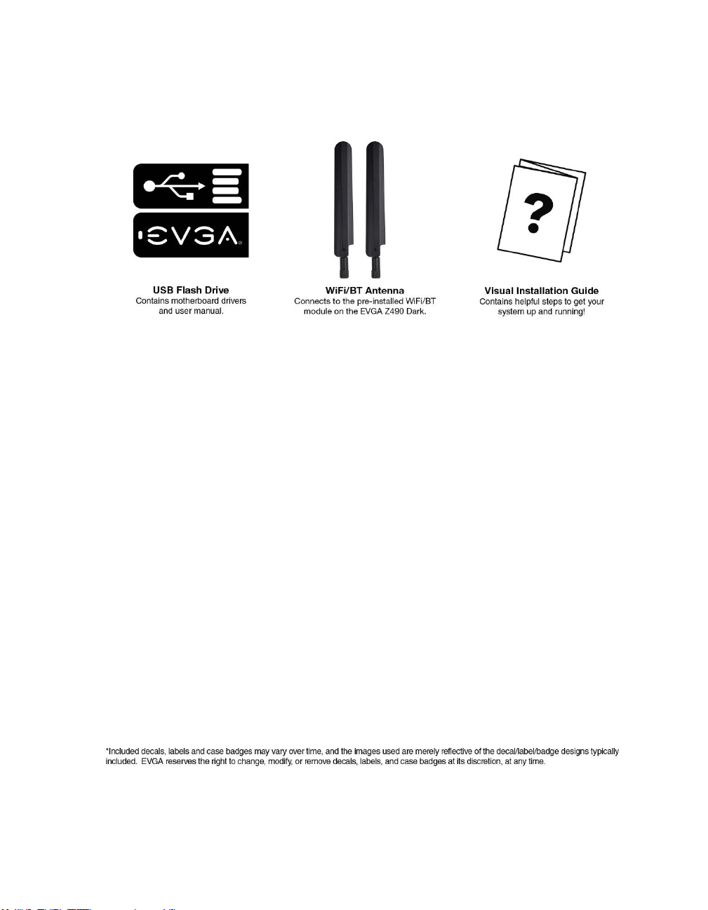
Unpacking and Parts Descriptions
The following accessories are included with the EVGA Z490 DARK
Motherboard:
Page 9
EVGA Z490 DARK (131-CL-E499)
- 9 -
Page 10

EVGA Z490 DARK (131-CL-E499)
- 10 -
EVGA Z490 DARK Motherboard LED
reference
The EVGA Z490 DARK Motherboard has several LEDs indicating power, connectivity,
and activity. Below is the location of the LEDs and their function.
Page 11
EVGA Z490 DARK (131-CL-E499)
- 11 -
1. M.2 Key-E Socket1 32mm
a. WHITE: M.2 can be used.
2. Multifunction POST Indicator
a. During boot it will cycle many different hexadecimal post codes with a
range of 00-FF and this indicates what aspect of the Power On Self Test
(POST) is currently running.
i. For a list of POST Codes, please see Page 157.
b. This indicator can be configured in BIOS to display hardware monitoring
information, such as voltage or temperature. After boot, these LEDs will
show either temperature or voltage, depending on user configuration in
the BIOS.
3. Memory DIMM 2 Status
a. OFF: DIMM detected and present
b. RED: DIMM/Memory has failed POST
4. Memory DIMM 1 Status
a. OFF: DIMM detected and present
b. RED: DIMM/Memory has failed POST
5. +5V Standby Power
a. WHITE: Voltage present (Does not mean PSU is outputting in-spec,
only that this specific voltage is detected)
6. CATERR - Catastrophic Error on the processor
a. RED: Processor error has occurred.
b. OFF: No error state detected in the CPU.
1. M.2 Key-E Ena bled 13. VCCST Status 25. M.2 Key-M PM1 Enabled
2. Multi-function POST indicator 14. VCCSTG Sta tus 26. U.2 PU1 Status
3. Memory DIMM 2 Status 15. VCCIO_1_2 Status 27. U.2 PU1 Enabled
4. Memory DIMM 1 Status 16. Power Button 28. PE2 Status
5. +5V Standby Power 17. Reset Button 29. PE2 Enabled
6. CATERR 18. BIOS 1 Active 30. M.2 Key-M PM2 Status
7. VCORE Status 19. BIOS 2 Active 31. M.2 Key-M PM2 Enabled
8. VDIMM Sta tus 20. BIOS 3 Active 32. PE3 Status
9. VSA Sta tus 21. SW Slow Mode ON 33. PE3 Enabled
10. VCCIO Status 22. PE1 Status 34 PE4 Status
11. VCCPLL Status 23. PE1 Enabled 35 PE4 Enabled
12. VPLL_OC Status 24. M.2 Key-M PM1 Status
LED Legend
Page 12

EVGA Z490 DARK (131-CL-E499)
- 12 -
7. VCORE status
a. WHITE: Voltage present (Does not mean PSU is outputting in-spec,
only that this specific voltage is detected)
8. VDIMM status
a. WHITE: Voltage present (Does not mean PSU is outputting in-spec,
only that this specific voltage is detected)
9. VSA Status
a. WHITE: Voltage present (Does not mean PSU is outputting in-spec,
only that this specific voltage is detected)
10. VCCIO Status
a. WHITE: Voltage present (Does not mean PSU is outputting in-spec,
only that this specific voltage is detected)
11. VCCPLL Status
a. WHITE: Voltage present (Does not mean PSU is outputting in-spec,
only that this specific voltage is detected)
12. VPLL_OC Status
a. WHITE: Voltage present (Does not mean PSU is outputting in-spec,
only that this specific voltage is detected)
13. VCCST Status
a. WHITE: Voltage present (Does not mean PSU is outputting in-spec,
only that this specific voltage is detected)
14. VCCSTG Status
a. WHITE: Voltage present (Does not mean PSU is outputting in-spec,
only that this specific voltage is detected)
15. VCCIO_1_2 Status
a. WHITE: Voltage present (Does not mean PSU is outputting in-spec,
only that this specific voltage is detected)
b. Inactive with Comet Lake-S processors.
16. Power Button
a. RED: Motherboard is turned on and running.
17. Reset Button
a. WHITE: Reset button will typically flash in conjunction with HDD/SSD
LED. Depending on load, the button may flash or appear solid at times.
b. NVMe SSDs cannot be read for the purposes of the Reset LED.
18. BIOS1 Active LED
a. WHITE: Active BIOS Chip (only 1 will be lit at a time)
19. BIOS2 Active LED
a. WHITE: Active BIOS Chip (only 1 will be lit at a time)
Page 13

EVGA Z490 DARK (131-CL-E499)
- 13 -
20. BIOS3 Active LED
a. WHITE: Active BIOS Chip (only 1 will be lit at a time)
21. SW Slow Mode ON
a. RED: Slow Mode switch has been set to enabled
22. PCIe Status for PE1. The LED stays off when PE1 is disabled or unpopulated.
a. WHITE: PE1 slot can be used with installed CPU.
23. PCIe Enabled for PE1. The LED stays off when PE1 is disabled or unpopulated.
a. GREEN: PE1 device present and detected.
24. M.2 Key-M Socket3 110mm (PM1) Status LED. The LED stays off when PM1
is disabled or unpopulated.
a. WHITE: PM1 slot can be used with installed CPU.
25. M.2 Key-M Socket3 110mm (PM1) Enabled LED. The LED stays off when PM1
is disabled or unpopulated.
a. GREEN: PM1 device present and detected.
26. U.2 PU1 Status
a. WHITE: Port is enabled.
b. OFF: No device is attached/Port is disabled.
27. U.2 PU1 Enable
a. GREEN: Port is connected to a working device.
b. OFF: No device is attached/Port is disabled.
28. PCIe Status for PE2. The LED stays off when PE2 is disabled or unpopulated.
a. WHITE: PE2 slot can be used with installed CPU.
29. PCIe Enabled for PE2. The LED stays off when PE2 is disabled or unpopulated.
a. GREEN: PE2 device present and detected.
30. M.2 Key-M Socket3 110mm (PM2) Status LED. The LED stays off when PM2
is disabled or unpopulated.
a. WHITE: PM2 slot can be used with installed CPU.
31. M.2 Key-M Socket3 110mm (PM2) Enabled LED. The LED stays off when
PM2 is disabled or unpopulated.
a. GREEN: PM2 device present and detected.
32. PCIe Status for PE3. The LED stays off when PE3 is disabled or unpopulated.
a. WHITE: PE3 slot can be used with installed CPU.
33. PCIe Enabled for PE3. The LED stays off when PE3 is disabled or unpopulated.
a. GREEN: PE3 device present and detected.
34. PCIe Status for PE4. The LED stays off when PE4 is disabled or unpopulated.
a. WHITE: PE4 slot can be used with installed CPU.
35. PCIe Enabled for PE4. The LED stays off when PE4 is disabled or unpopulated.
a. GREEN: PE4 device present and detected.
Page 14
EVGA Z490 DARK (131-CL-E499)
- 14 -
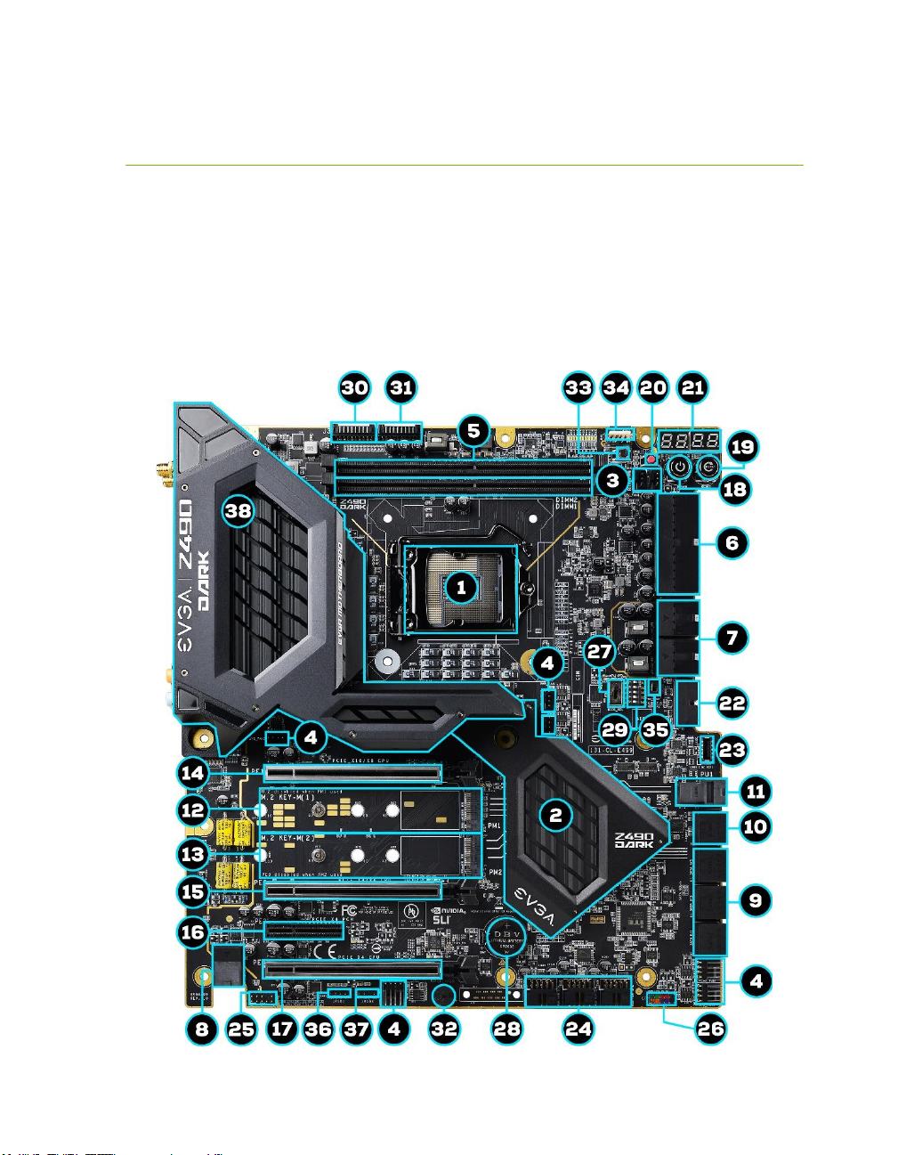
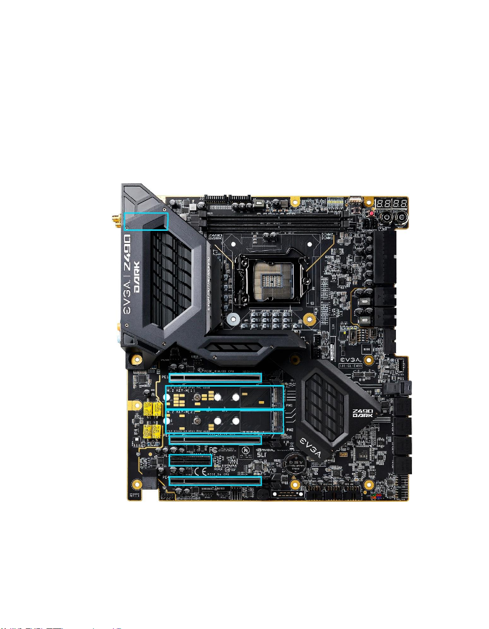
EVGA Z490 DARK Motherboard Component
Legend
The EVGA Z490 DARK Motherboard with the Intel® Z490 and PCH Chipset.
Figure 1 shows the motherboard and Figure 2 shows the back panel connectors
FIGURE 1. Z490 DARK Motherboard Layout
Page 15
EVGA Z490 DARK (131-CL-E499)
- 15 -
**For a FULL description of the above legend, please see Page 17.
1.
CPU Socket LGA1200
14.
PCIe Slot x16/x8
27.
BIOS Selector Switch
2.
Intel Z490 PCH
15.
PCIe Slot x8/x4
28.
CMOS Battery
3.
PWM Fan Headers (2 amp)
16.
PCIe Slot x4
29. PCIe Disable Switches
4.
PWM/DC Fan Headers (2 amp)
17.
PCIe Slot x4 (x16 Mechanica l)
30. ProbeIt Header J3
5.
DDR4 Memory DIMM Slots 1, 2
18.
Power Button
31.
ProbeIt Header J5
6.
24-pin ATX Power Connector
19.
Reset Button
32.
PC Speaker
7.
8 pin EPS Power Connector
20. CMOS Reset Button 33. BIOS Safeboot Button
8.
Supplemental PCIe 6 pin power
21. Multi-function POST Indicator 34.
USB to SPI for BIOS Fla sh
9.
Intel Sata 6G RAID Ports
22.
USB 3.2 Gen1 Header
35.
SW Slow Switch
10.
ASMedia Sata 6G Ports
23.
USB 3.2 Gen2 Type-C Header
36.
RGB LED Controller Header
11.
U.2 (SFF-8643) Port
24.
USB 2.0 Headers
37.
ARGB LED Controller Hea der
12.
M.2 Socket 3 Key-M 110mm (PM1)
25.
Front Panel Audio Connector
38.
Rear Panel I/O (Figure 2)
13.
M.2 Socket 3 Key-M 110mm (PM2)
26.
Front Panel Connectors
Component Legend
Page 16

EVGA Z490 DARK (131-CL-E499)
- 16 -
Figure 2. Chassis Rear Panel Connectors
1. PS/2 (Keyboard+Mouse) 5. Intel i219V GbE NIC 9. USB 3.2 Gen2 Type-C
2. USB 3.2 Gen1 6. Intel i225V 2.5GbE NIC 10. Optical Out
3. Intel® WiFi/BT 7. USB 3.2 Gen2 Type-A 11. Ana log Audio Jacks
4. BIOS/CMOS Reset 8. Mini-DisplayPort
I/O Hub
Intel i225V
Activity LED Status Description Speed/Link LED Status Description
Off No Data Transmission Orange 2.5Gbps data rate
Blinking (Green) Data Transmission Green 1 Gbps data rate
Off 10/100 Mbps data rate or No Link
Intel i219V
Activity LED Status Description Speed/Link LED Status Description
Off No Data Transmission Orange 1000Mbps data rate
Blinking (Green) Data Transmission Green 100 Mbps data rate
Off 10 Mbps data rate or No Link
Page 17

EVGA Z490 DARK (131-CL-E499)
- 17 -
Component Legend Descriptions
1. CPU Socket 1200
This is the interface for the Central Processing Unit (CPU), and supports 10th
Gen. Intel Core i3, i5, i7 and i9 models compatible with the Intel® LGA1200
Socket, based on Comet Lake-S architecture.
2. Intel® Z490 PCH
The Platform Controller Hub (PCH) handles the role that was previously held
by the South Bridge. The PCH has 4 PCIe Gen 3 lanes and allocates bandwidth
to smaller PCIe slots, M.2, USB, audio, etc. In simplified terms, the PCH works
as a hub for peripherals that are less bandwidth-intensive.
3. PWM Fan Headers
4-pin fan headers that control the fan speed based on a configurable curve or
static percentage. PWM (Pulse-Width Modulation) works by pulsing power to
the fan at a constant rate and sending the RPM signal to the fan’s controller via
a Sense cable, rather than adjusting fan speed by increasing and decreasing
voltage. This method is preferable because it eliminates voltage-based fan stall
points. Please see Page 92 for more in-depth PWM breakdown and PWM
controls within BIOS/UEFI.
These headers also support 12v. DC fans. However, DC fan speed is based on
decreasing voltage to the fan, starting at a default of 100%/12V. When using a
12v. fan, the minimum speed will vary depending on the motor because most
fan motors require a set amount of voltage before stalling.
4. PWM/DC Fan Headers
These ports may be used with both DC and PWM fans, and may be controlled
via Smart Fan or manually within the BIOS.
5. DDR4 Memory Slots
The memory slots support up to two 288-pin DDR4 DIMMs in Dual-Channel
mode. Dual-Channel mode will be enabled only upon using two sticks of
supported memory; using one stick of memory will lower the board to SingleChannel mode, which may significantly lower performance. 64GB of RAM is
supported in a 2x32GB configuration. At the time of this manual’s release, this
motherboard officially supports up to 4800MHz+ speeds. These speeds cannot
be guaranteed, however, because Intel® only certifies the speed of the memory
controller up to 2933MHz for Comet Lake-S processors.
Page 18

EVGA Z490 DARK (131-CL-E499)
- 18 -
6. 24-pin ATX power connector
The main power for the motherboard is located on the right side of the board
and parallel to the PCB; this is also described as a “90 degree / right-angle”
connector (See Page 41 for more specifics to the connector itself, and associated
wiring/pinouts). The 24-pin connector IS directional and the connector needs
the tab on the socket to line up with the release clip located on the 24-pin
connector from the power supply. This connector pulls the bulk of the power
for all components; other connectors, such as EPS and PCIe, have been added
to reduce the load and increase longevity due to wiring and trace limitations.
7. Dual 8-pin EPS Connectors
The +12V EPS are comprised of 90 degree right-angle dual-dedicated power
inputs for the CPU (See Page 42 for more specifics to the connector itself, and
associated wiring/pinouts). Carefully choose the correct power cable by
consulting with the installation manual for your power supply. This connector
is designed only to work with an EPS or CPU cable. System builders may make
the mistake of plugging in a PCIe 8-pin or 6+2-pin connector, which will
prevent the board from POSTing and possibly short or damage the board.
Although the cables appear similar, they are wired differently and attaching a
PCIe cable to an EPS connector may cause damage to the motherboard.
Alternatively, if no power cable is connected or detected, the system will not
POST and will hang at POST code “C.”
8. Supplemental PCIe 6-pin Power Connector
There is a 6-pin PCIe connector at the bottom of the motherboard (See Page 41
for more specifics to the connector itself, and associated wiring/pinouts). This
connector provides dedicated power to the PCIe x16 slots, augmenting the
+12V power provided by the 24-pin and the GPU directly.
This is optional for a single card solution, but is recommended for SLI, CFX,
and dual-processor video cards.
9. Intel® SATA 6Gbit/s Ports
The Intel® Z490 PCH has a 6-port SATA 3/6 Gbit/s controller (See Page 51
for specifics on the connectors). This controller is backwards compatible with
SATA and SATA II devices, and supports SSDs, HDDs and various types of
optical devices (CDROM, DVDROM, BD-ROM, etc). The controller also
supports NCQ, TRIM, hot swap capability, and RAID levels 0/1/5/10.
Page 19

EVGA Z490 DARK (131-CL-E499)
- 19 -
10. ASMedia SATA 6Gbit/s Ports
This is a secondary SATA controller, the ASM1061 is a 2-port SATA3/6
Gbit/s controller with legacy support for older operating systems. This is
included largely for benchmarking and overclocking with very specific
programs, such as Super Pi, 3DMark, PCMark, etc. This board is not
guaranteed to fully support any OS prior to Windows 10 x64, as we offer no
drivers for legacy OS (See Page 51 for specifics on the connectors).
11. U.2 Port (SFF-8643)
U.2, originally known as SFF-8643, is a high bandwidth connection specifically
engineered for next generation SSDs. U.2 brings PCIe x4 (Gen3) NVMe
performance to a 2.5” SSD form factor and provides a solution to potential
heating problems that may be present in some M.2 solutions. Port function
depends upon BIOS Configuration. Note: SFF-8643 ports are located on the
motherboard side; SFF-8639 ports are located on the storage side.
12. M.2 Socket 3 Key-M 110mm (PM1)
M.2 is an SSD form factor standard, which uses up to four PCIe lanes and
utilizes Gen3 speeds. Most popularly paired with NVMe SSDs, this standard
offers substantially faster transfer speeds and seek time than SATA interface
standards. All M.2 devices are designed to connect via a card-bus style
connector and be bolted into place and powered by the connector, rather than
by a dedicated data cable and power cable.
This socket will support Key-M devices of 110mm, 80mm, 60mm, and 42mm
length.
This connector can utilize only PCIe/NVMe-based M.2 SSDs, or Intel®
Optane™ NVMe devices.
13. M.2 Socket 3 Key-M 110mm (PM2)
M.2 is an SSD form factor standard, which uses up to four PCIe lanes and
utilizes Gen3 speeds. Most popularly paired with NVMe SSDs, this standard
offers substantially faster transfer speeds and seek time than SATA interface
standards. All M.2 devices are designed to connect via a card-bus style
connector and be bolted into place and powered by the connector, rather than
by a dedicated data cable and power cable.
This socket will support Key-M devices of 110mm, 80mm, 60mm, and 42mm
length.
This connector can utilize only PCIe/NVMe-based M.2 SSDs, SATA M.2, or
Intel® Optane™ NVMe devices.
Page 20

EVGA Z490 DARK (131-CL-E499)
- 20 -
14. PCIe Slot x16/x8*
PCIe x16/x8 slots are primarily used for video cards. These full-length slots
will provide 8 or 16 lanes of bandwidth to a full-size card, and are backwardscompatible with x8, x4, and x1-length cards.
Comet Lake-S has 16 PCIe lanes available for routing.
15. PCIe Slot x8/4*
PCIe x8/4 slot can be used for video cards or other devices. PE2, the only
x8/x4 slot on the board, receives either x8 lanes or x4 from the CPU (Page
27), depending upon the peripheral configuration. These full-length slots will
provide up to 8 lanes of bandwidth to a full-size card, and are backwardscompatible with x8, x4, and x1-length cards.
Comet Lake-S has 16 PCIe lanes available for routing.
16. PCIe Slot x4*
PCIe x4 slot PE3 uses up to 4 Gen 3 lanes from the PCH. This slot is typically
used for sound cards, WiFi, USB, LAN or other peripheral cards. Using this slot
will have no effect on the bandwidth or throughput of the x16 slots used for
SLI because this slot uses only PCH bandwidth.
17. PCIe Slot x4* (x16 Mechanical)
PCIe x4 slot can be used for video cards or other devices. PE4, the only full
x16 mechanical slot that runs at x4 electrically, receives either x4 lanes or x0
from the CPU (Page 27), depending upon the peripheral configuration. These
full-length slots will provide up to 4 lanes of bandwidth to a full-size card, and
are backwards-compatible with x1-length cards.
PCIe x4 slot PE4 uses up to 4 Gen 3 lanes from the CPU. This slot shares 4
lanes with PE2, and will change both PE2 and PE4 to x4 lanes. Using this slot
will disable SLI because SLI requires at least 2 slots capable of x8 bandwidth.
Comet Lake-S has 16 PCIe lanes available for routing.
18. Power Button
This is an onboard power button, and may be used in place of, or in
conjunction with, a front panel power button wired to the board.
Benching systems, or test benches before final assembly, are best served by
using the onboard power because it removes the need to wire a Power/Reset
button or cross posts with a screwdriver, which is a semi-common practice.
This button provides a safer and easier option than jumpering the Power posts.
Page 21

EVGA Z490 DARK (131-CL-E499)
- 21 -
19. Reset Button
This is an onboard system reset button, and may be used in place of, or in
conjunction with, a front panel system reset button wired to the board.
Benching systems, or test benches before final assembly, are best served by
using the onboard power because it removes the need to wire a Power/Reset
button or cross posts with a screwdriver, which is a semi-common practice.
This button provides a safer and easier option than jumpering the Power posts.
20. CMOS Reset Button
This button has two main uses: the first is standard practice to clear BIOS and
power on before updating the BIOS, and the second is standard practice when
troubleshooting instances when the motherboard fails to POST, such as after
upgrading RAM or CPU, installing new hardware, a failed overclock, etc. This
button provides a much faster means of resetting than the previous method of
removing power from the board, removing the CMOS battery, and discharging
power to the board. In rare occasions the older method can help; pressing the
clear CMOS button will normally allow you and your system back into the
default BIOS.
21. Multi-function POST Indicator
This is a four-digit POST code reader, which displays in sets of 7-digit LED.
The display can be configured to show data in regular decimal format, or
hexadecimal, which means the characters available (when working as intended)
are 0-9, A-F and has a cap of 255 characters.
During POST, the left set of LEDs will display the various POST codes as they
cycle through the Power On Self-Test. The POST codes are listed in the
troubleshooting section on Page 157.
After the system boots, these same set of LEDs can be set to display a hardware
monitoring sensor, such as the CPU temperature in Celsius. This temperature
is specifically for the CPU socket, which will typically read slightly higher than a
given CPU core. To read this temp in Fahrenheit, take the value in Celsius,
multiply by 9/5 (or 1.8) and add 32.
The display can be used to show additional temperatures, or can be configured
in tandem with all 4 digits to provide live readings for voltages or temperatures.
For example, the LEDs can be configured to read voltages, such as 1.258 or 55C for CPU temp for when you are using LN2 extreme cooling. Detailed
configuration instructions for the Debug Indicator are provided on Page 153.
Page 22

EVGA Z490 DARK (131-CL-E499)
- 22 -
22. USB 3.2 Gen1 Header
The USB 3.2 Gen1 header is used to connect additional USB interface plugs to
the motherboard; these headers are most often used to connect the
motherboard to the chassis to enable the USB 3.2 Gen1 ports on the chassis.
These will function similarly to the USB 3.2 Gen1 ports found on the
motherboard’s rear I/O hub, but can also be used for the chassis’ front panel
USB, auxiliary ports that mount in the card slots, and certain devices that
directly connect to the header.
USB 3.2 Gen1 standard is 900ma @ 5V for unpowered devices. If your USB
device requires more power, it is recommended to attach a powered USB Hub.
USB 3.2 Gen2 Type-A (found on the I/O Hub) shares the power limit of USB
3.2 Gen1 at 900ma @ 5V.
Note: USB 3.2 Gen1 is more commonly referred to as USB 3.0.
23. USB 3.2 Gen2 Type-C Header
The USB 3.2 Gen2 header is used to connect additional USB interface plugs to
the motherboard; these headers are most often used to connect the
motherboard to the chassis to enable the USB 3.2 Gen2 ports on the chassis.
These will function similarly to the USB 3.2 Gen2 Type-C port sometimes
found on a motherboard’s rear I/O hub, but can also be used for the chassis’
front panel USB, auxiliary ports that mount in the card slots, and certain
devices that directly connect to the header. The USB 3.2 Gen2 Header on the
Z490 DARK is a shielded USB 3.2 Gen2 Header and supports up to 10Gb/s
with USB 3.2 Gen2.
This USB 3.2 Gen2 Header has a power limit of 3000ma (3A) @ 5V.
24. USB 2.0 Headers
The USB2.0 header is used to connect additional USB interface plugs to the
motherboard; these headers are most often used to connect the motherboard to
the chassis to enable the USB2.0 ports on the chassis. These will function the
same as the USB2 ports found on the motherboard’s hardwired I/O hub, but
these can be used to attach to front panel USB, auxiliary ports that mount in the
card slots, and also some devices that directly connect to the header.
USB 2.0 standard is 500mA @ 5V per port (header total is 1000mA) for
unpowered devices. If your USB device requires more power than this, it is
recommended to attach a powered USB Hub.
Page 23

EVGA Z490 DARK (131-CL-E499)
- 23 -
25. Front Panel Audio Connector
This is a motherboard header, which is used to plug in the audio cable
originating from most PC chassis to allow audio to be recorded from or played
through the audio connectors on the chassis. This header has a connector that
looks similar to the USB2.0 header and uses the standard “HD Audio” jack.
Some chassis may have two cables: HD Audio, and one labeled AC’97 – an
AC’97 cable is not compatible with this header on the Z490 DARK.
26. Front Panel Connectors
The Front panel connectors are the four main chassis connections. These
include the Power Switch, Power LED, Reset Switch, and HDD LED. The
Power and Reset switches are both designed to use “Momentary Switches,”
rather than “Latching Switches,” which means the connection between the two
posts needs to be made just briefly for it to work, as opposed to being held in
place. This is why the Power and Reset switches can be triggered with a screw
driver by simultaneously touching the + and - posts.
Power LED will power on with the system, indicating the system is on and can
blink with CPU activity.
HDD LED will blink during access to the SATA ports; this is not activated for
M.2 SSDs.
27. BIOS Selector Switch
This switch toggles between physical BIOS chips. This board has 3 BIOS chips
as a permanent fixture. Each chip holds only the settings and profiles that have
been saved to the BIOS chip while active. This allows you to swap between
three physically different BIOS chips. Similarly, you can update each BIOS via
the USB Update Port, even if you cannot POST into BIOS. If instructions are
needed for updating the BIOS via the Update Port, please go to Page 147.
28. CMOS Battery
The +3V CMOS battery backup provides uninterruptable power to the
BIOS/UEFI to keep all of the settings; otherwise, each boot would behave like
you just reset the BIOS. These batteries typically last several years and rarely
need to be replaced.
29. PCIe Disable Switches
These are DIP switches to physically disable power to a specific PCIe slot. By
default, all switches are in the “On” position to the left. Move the switch to the
right to disable a specific slot. From top to bottom, the switches correspond to
PE1, PE2, and PE4. PE3 is always on. Switches 4 and 5 are disabled.
Page 24

EVGA Z490 DARK (131-CL-E499)
- 24 -
30. ProbeIt Header J3
The ProbeIt header is a means of live monitoring several different system
voltages in real-time with a multimeter. One terminal needs to connect to a
ground wire and the other to the specific voltage you want to monitor.
From left to right the function for the J3 connector: VCORE/Ground,
VDIMM/Ground, VGT/Ground, VSA/Ground, and VCCIO/Ground.
31. ProbeIt Header J5
The ProbeIt header is a means of live monitoring several different system
voltages in real-time with a multimeter. One terminal needs to connect to a
ground wire and the other to the specific voltage you want to monitor.
From left to right the function for the J5 connector: VCCPLL/Ground,
VCCPLL_OC/VCCSTG, VCCST/VCCIO12, PCH/Ground, and
DMI/Ground.
32. PC Speaker
This is a small mono low-fidelity speaker permanently attached to the
motherboard used mainly for debugging purposes. A POST beep may indicate
a successful POST, various tones for USB initialization, and other beeps to
indicate an issue during the post process. Please see Page 155 for more details.
33. BIOS SafeBoot Button
Pressing this button while the system is running will reboot the motherboard
directly into the BIOS without clearing CMOS. This feature is very useful for
situations where the motherboard is unable to complete boot due to a failed
overclock and the user does not want to erase the previous settings used.
34. USB to SPI for BIOS Flash
This USB port is designed to connect directly to the motherboard to allow the
motherboard BIOS to be flashed, even if no CPU is installed. For more
information on how to flash your BIOS using this method, please see Page 147.
35. SW Slow Mode Switch
This switch forces the CPU clock ratio to the lowest possible value (8.0 for
Comet Lake-S CPU) in real-time. This can be helpful for benchmarking and
performance tuning, especially with extreme overclocking. Active Slow Mode is
indicated by a red LED near the switch. This is a hardware-based function and
does not need any BIOS settings or software to operate.
Page 25

EVGA Z490 DARK (131-CL-E499)
- 25 -
36. RGB LED Controller Header
The RGB header is a 12V. 4 pin header with a current limit of 2A; anything
above 2A will trigger overcurrent protection and lock at 2A. This header allows
for software-based control within Windows for RGB devices via EVGA
ELEET X1. Please see Page 46 for header specifics, and Page 139 for control
options in ELEET X1.
37. ARGB LED Controller Header
The ARGB header is a 5V. 3 pin header with a current limit of 2A; anything
above 2A will trigger overcurrent protection and lock at 2A. This header allows
for far more flexible options to configure your RGB lighting via software-based
control within Windows via EVGA ELEET X1, and supports up to 125 LEDs.
Please see Page 45 for header specifics, and Page 139 for control options in
ELEET X1.
38. Rear Panel IO (Figure 2)
This is the section referred to as the I/O Hub. This panel contains the
hardwired USB, Sound, and Ethernet connections. Please see Page 16 for a
component level breakdown.
* There are two numeric references for PCI Express: one is mechanical, which is the
actual slot-length footprint, and the second is electrical, which is a reference of how
many PCIe lanes are routed to the slot.
Because PCI-Express was designed to be a universal architecture, you can install x1
cards, such as sound cards or USB controllers into an x16 slot. Many types of cards can
use different amounts of PCIe lanes, while some applications use only certain parts of a
card, such as compute apps that allow a card to run off of a single PCIe lane. This is
why there are x16 mechanical slots with an x1 electrical PCIe lane. Using the entire
length of a PCIe slot is unnecessary, nor does it cause an adverse effect to use a shorter
form-factor bus card in a slot that physically can hold a larger form-factor bus card.
Page 26
EVGA Z490 DARK (131-CL-E499)
- 26 -
Card Slots
The Z490 DARK features three x16 PCIe slots, one x4 PCIe slot, two Socket 3
Key-M M.2 110mm slots (PM1/PM2) (backwards compatible with Key-M 80mm,
60mm, and 42mm), and a vertical Socket 1 Key-E M.2 (Contains the WiFi module).
*Note: The M.2 Key-E 32mm slot is accessible only after removing the cover over
the rear panel connectors.
Page 27

EVGA Z490 DARK (131-CL-E499)
- 27 -
PCIe Slot Breakdown
PCIe Lane Distribution (All Socket 1200
processors are 16 lanes.)
PE1 – x16 (Gen3, x16 lanes from CPU, x8 shared with PE2)
PE2 – x8 (Gen3, x8 lanes from CPU, x4 shared with PE4)
PE3 – x4 (Gen3, x4 lanes from PCH)
PE4 – x4 (Gen3, x4 lanes from CPU, shares 4 of PE2’s 8 lanes)
M.2 / U.2 Slot Breakdown
M.2 Lane Distribution
M.2 Key-M (110mm, Top, PM1) – x4 from Z490 PCH
o M.2 Enable/Disable is set within the BIOS
o This M.2 Key-M slot shares lanes with the U.2 port. Installing an M.2
device will disable U.2 port PU1.
M.2 Key-M (110mm, Bottom, PM2) – x4 from Z490 PCH
o M.2 Enable/Disable is set within the BIOS
o This M.2 Key-M slot shares lanes with PE3. Installing an M.2 device will
disable PCIe slot PE3.
M.2 Key-E (32mm) – x1 from Z490 PCH
o M.2 Enable/Disable is set within the BIOS
U.2 Lane Distribution
U.2 (PU1) – x4 from Z490 PCH
o U.2 Enable/Disable is set within the BIOS
o This U.2 port shares lanes with the M.2 Key-M slot PM1. Installing a
U.2 device will disable PM1.
Page 28
EVGA Z490 DARK (131-CL-E499)
- 28 -
Preparing the Motherboard
Installing the CPU
Note: EVGA strongly recommends that you completely disconnect AC power from
your power supply prior to changing your CPU. This ensures the
motherboard will use the correct startup procedure for all onboard devices. If
AC power is not disconnected, the replacement is still supported, but may
require additional reboots to boot successfully.
Be very careful when handling the CPU. Hold the processor only by the edges and do
not touch the bottom of the processor.
Note: Use extreme caution when working with the
CPU to avoid damaging the pins in the
motherboard’s CPU socket!
Do not remove the socket cover until you have
installed the CPU. This installation guide was
created without using a socket cover to better
illustrate the CPU Socket area. However,
users should remove the cover as the last
step, not the first step.
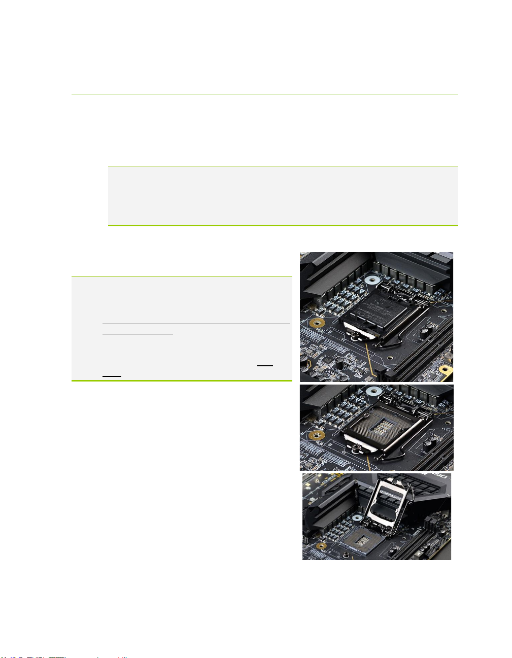
Use the following procedure to install the CPU
onto the motherboard.
1. Unhook the socket lever by pushing
down and towards the socket.
2. Pull the socket levers back and gently lift
the load plate to open the socket. Make
sure to avoid touching or dropping items
into the socket; otherwise, you may
damage the board socket and/or CPU
pins, which may void your warranty.
Page 29

EVGA Z490 DARK (131-CL-E499)
- 29 -
3. Align the notches on the CPU to the
notches in the socket, and lower the
processor straight down into the socket.
Note: The gold triangle key on the CPU
should match the triangle key on
the load plate.
Note: Make sure the CPU is fully seated
and level in the socket.
4. Lower the load plate so that it is resting
on the CPU.
5. Carefully lock the lever back into place
by lowering it down to the hook, then
push the lever towards the socket and
down under the hook.
6. Remove the plastic protective socket
cover by pulling it straight up and away
from the socket.
Note: After removing the CPU socket cover, it is recommended to store it in case
you ever need to transport your motherboard. If you ever remove the CPU, it
is highly recommended to reinstall the socket cover.
Installing the CPU Cooling Device
There are many different cooling devices that can be used with this
motherboard. Follow the instructions that come with your cooling assembly.
Page 30

EVGA Z490 DARK (131-CL-E499)
- 30 -
Installing System Memory
Your Z490 DARK has (2) 288-pin slots for
DDR4 memory. These slots support 4GB,
8GB, 16GB, and 32GB DDR4 Unbuffered
non-ECC DIMMs. There must be at least
one memory slot populated for the board to
boot and operate.
The Z490 DARK supports Dual-Channel
DDR4 memory, a maximum of 64GB and
up to 4800MHz+ (OC) for Comet Lake-S.
It is recommended to always use a 2 DIMM
Dual Channel kit for the Z490 DARK.
Fill the memory slots in the following
order: 1, then 2. See chart to the right:
Use the following procedure to install
memory DIMMs. Note that there is a
key notch near the center of the DIMM slots. This matches the gap on
a DDR4 DIMM to ensure the memory is installed properly, and to prevent the
incorrect installation of memory.
1. Unlock a DIMM slot by pressing the module clips outward.
2. Align the memory module to the DIMM slot, insert the module
vertically into the slot, and press straight down to fully seat the module.
The plastic clips at top side of the DIMM slot should automatically
lock the DIMM into the connector.
Note: The memory controller on most Comet Lake-S CPUs runs at a default
frequency of 2933MHz on 10- and 8-core processors, but only 2666MHz on
6-core processors. Achieving memory speeds above the CPU’s default speed
may require manual setting of the memory timings, frequency and voltages
and/or overclocking of the CPU.
Refer to the memory manufacturer specifications for the recommended
memory timings. For overclocking support you can visit our forums:
https://forums.evga.com/
Slot 1 Slot 2
1 DIMM
X N/A
2 DIMM
X X
Comet Lake-S RAM Slot Fill Order
Page 31

EVGA Z490 DARK (131-CL-E499)
- 31 -
Installing the I/O Shield
The motherboard kit comes with an I/O shield that is used to block internal
components from dust and foreign objects, while also promoting correct
airflow within the chassis.
Before installing the motherboard, install the I/O shield from the inside of the
chassis. Press the I/O shield into place and make sure it fits securely.
Installing the Motherboard
Installing the motherboard into a system case depends on several factors:
whether you are replacing an existing motherboard, whether you are building a
new PC, and the type of chassis that will house your PC components. You must
first determine if it would be easier to secure the motherboard to the chassis or
if it would be easier to install other components prior to this step. It is normally
easier to secure the motherboard first.
Note: Make sure that the CPU fan assembly has enough clearance for your
installed DIMMs, expansion cards, and for the case side panels to lock into
place. Also, make sure the CPU fan assembly aligns with the vents on the
case side and back panels; correctly aligned, airflow will properly exhaust
from the chassis. The CPU fan assembly orientation will depend upon both
the CPU fan manufacturer’s instructions and your chosen chassis.
Page 32

EVGA Z490 DARK (131-CL-E499)
- 32 -
Securing the Motherboard into a System Case
Most system cases require installation of standoffs into the chassis to allow the
motherboard to be mounted to the chassis and prevent short circuits. If there are
any studs that do not align with a motherboard mounting hole, we recommend that
you remove that standoff to prevent the possibility of a short circuit. Furthermore,
ensure that all standoffs are fully tightened prior to mounting the motherboard to
the chassis. Please review the installation manual included with your chassis for the
proper installation of the motherboard standoffs.
1. Carefully place the motherboard onto the standoffs located inside the
chassis.
2. Align the mounting holes with the standoffs.
3. Align the connectors to the I/O shield and/or I/O cover.
4. Ensure that the fan assembly aligns with the chassis vents according to the
fan assembly instruction.
5. Secure the motherboard with ten (10) screws (See next page for mount hole
location). Ensure that each screw is lined up with and fastened to its
corresponding standoff under the board. Double-check alignment to make
sure nothing gets cross-threaded.
Tip: If you have difficulty fastening some of the screws, especially near the
I/O hub, first try to loosely fasten all other screws on the motherboard, but
don’t completely tighten the screws. This may help to hold the board in
place, allowing you to thread and fasten the remaining screws. Once all
screws are properly threaded, remember to go back and tighten the rest of
the screws.
6. See the picture below for the locations of standoff holes for the Z490
DARK.
Page 33

EVGA Z490 DARK (131-CL-E499)
- 33 -
1. All safe locations to secure the board to a standoff are circled in blue.
2. Keep in mind that when the screws are installed, but not fully
tightened, the motherboard should have 1-2mm of movement; this can
help when mounting cards or tight-fits with other components.
3. Once the board is properly aligned, be sure to fully-tighten the board to
the chassis before proceeding.
Page 34

EVGA Z490 DARK (131-CL-E499)
- 34 -
Installing M.2 devices
Installing M.2 Key-M Socket 3 Devices
Securing an M.2 device to the motherboard requires a few extra steps compared to other
current drive or slot-based connectors. M.2 devices used on this motherboard - Socket
3 (for SSDs) and Socket 1 (for WiFi/Bluetooth) – are installed differently.
Below are images from an installation of an SSD on the Socket 3 Key-M 110mm PM1
slot of the Z490 DARK.
1. Before you can install an M.2 device, you must
first remove the screw that comes pre-attached to
the Socket 3’s retention standoff; this will be used
to keep the device in place. The standoff is placed
at the 80mm interval for the Socket 3 slot. There
are also additional standoffs available for different
size drives, such as 110mm Intel 905P Optane
SSDs.
Next add one thermal pad – included with the
Z490 DARK accessories – to the outlined area to the right.
2. After adding the thermal pad, the motherboard will look like the image below. This
thermal pad will assist with cooling your M.2 Key-M device.
Page 35

EVGA Z490 DARK (131-CL-E499)
- 35 -
3. Insert the M.2 device at a slight angle of
approximately 45 degrees to the board.
This will allow the contacts (colloquially
called “Gold Fingers”) to seat completely
into the slot. If the device is fully seated,
you should be able to release it and the
device will rest at an angle of about 30
degrees on its own, as shown in the picture
to the right.
4. Gently push the M.2 device down on
the raised end. There will be some tension
- this is normal - then use the screw you
removed in Step 1 to secure the device.
At right, you can see that the contacts will
be nearly invisible when the device is
properly seated and the copper mounting
semi-circle is partially visible around the
screw.
Page 36

EVGA Z490 DARK (131-CL-E499)
- 36 -
Incorrect installation Example:
*NOTE* This is one of the most common examples of an incorrect installation
of an M.2 device. Do not intentionally attempt this, or complete your installation
with this example. Doing so could cause damage to the device or the M.2 port.
Using the image below, notice how the gold fingers fail to fully seat in the M.2 slot. This
often occurs if the drive was pushed into the slot from a nearly parallel starting position,
rather than an angle, causing the M.2 device to not seat fully. As a result, this may cause
a drive detection failure by the BIOS, the drive will be detected with the description in
gibberish (e.g. characters in the name, such as @, #, $, %, *, etc.) and/or notifications
that the drive has corrupt data stored on it.
Moreover, if the device’s connection looks like this, then screwing down the device may
be impossible (a VERY tight fit, at best), which is another sign that the device is not
seated properly.
In conclusion, if the install device looks similar to the image below, please remove and
reseat it using the instructions above. DO NOT POWER THE SYSTEM ON IF
THE CONNECTOR RESEMBLES THIS PICTURE.
For further M.2 setup instructions, please see Page 54.
Page 37

EVGA Z490 DARK (131-CL-E499)
- 37 -
Tested CPU and Memory
Tested Memory
For a full list of tested CPUs and Memory, please visit
https://www.evga.com/support/motherboard/ and select the EVGA Z490
DARK from the list.
CPU Core Count Frequency PCI-E Lanes
Core ™ i9 10900KF
10 Cores +HT 3.70 GHz 16
Core ™ i9 10900K
10 Cores + HT 3.70 GHz 16
Core ™ i9 10900F
10 Cores + HT 2.80 GHz 16
Core ™ i9 10900
10 Cores +HT 2.80 GHz 16
Core ™ i7 10700KF 8Cores + HT 3.80 GHz 16
Core ™ i7 10700K 8Cores + HT 3.80 GHz 16
Core ™ i7 10700F 8Cores + HT 2.90 GHz 16
Core ™ i7 10700 8Cores + HT 2.90 GHz 16
Core ™ i5 10600KF 6 Cores + HT 4.10 GHz 16
Core ™ i5 10600K 6 Cores + HT 4.10 GHz 16
Core ™ i5 10600 6 Cores + HT 3.30 GHz 16
Core ™ i5 10500 6 Cores + HT 3.10 GHz 16
Core ™ i5 10500T 6 Cores + HT 2.30 GHz 16
Core ™ i5 10400F 6 Cores + HT 2.90 GHz 16
Core ™ i5 10400 6 Cores + HT 2.90 GHz 16
Core ™ i5 10400T 6 Cores + HT 2.00 GHz 16
Core ™ i3 10320 4 Cores + HT 3.80 GHz 16
Core ™ i3 10300 4 Cores + HT 3.70 GHz 16
Core ™ i3 10300T 4 Cores + HT 3.00 GHz 16
Core ™ i3 10100 4 Cores + HT 3.60 GHz 16
Core ™ i3 10100T 4 Cores + HT 3.00 GHz 16
Comet Lake-S
Page 38

EVGA Z490 DARK (131-CL-E499)
- 38 -
Tested M.2 Key-M
ADATA ASX8000NP-256GM-C 256G M.2 PCIE
Samsung MZ-VKV512 950 PRO
Samsung MZ-V6P512 960 PRO
Samsung MZ-VPV2560 256G SM951 NVME
Samsung MZ-HPU128T/004 128G XP941
Samsung MZ-HPV1280 128G SM951
Samsung MZ-V6E250 250G 960EVO
Samsung MZ-MZ-VPW2560 256G SM961
Samsung MZ-VLW2560 256G PM961
Samsung MZ-VLB2560 256G PM981
INTEL 600P SERIES SSDPEKKW512G7 M.2 512G PCIE
INTEL 600P SERIES SSDPEKKW256G7 M.2 256G PCIE
INTEL 760P SERIES SSDPEKKW010T8 M.2 1TB PCIE
Kingston SKC1000240G
Kingston SHPM2280P2H/240G
PLEXTOR PX-128M8PeG M.2 128G PCIE
TOSHIBA THNSN5256GPU7 M.2 256G PCIE
WD PC SN520 SDAPNUW-512G-1006 512G NVME M2
WD PC SN700 WDS100T2X0C-00L350 1T NVME M2
WD PC SN750 WDS100T3X0C-00SJG0 1T NVME M2
WD Blue SN500 WDS500G1B0C-00S6U0 500G PCIE3.0 NVME M2
WD Blue SN550 WDS100T2B0C-00PXH0 1TB PCIE3.0 NVME M2
CORSAIR MP500 CSSD-F240GBMP500 240G PCIE3.0 NVME M2
PCIE INTERFACE
Page 39

EVGA Z490 DARK (131-CL-E499)
- 39 -
Tested U.2
Tested M.2 Key-E
Brand Part Number Size Interface
Intel 750 SSDPE2MW400G4 400GB U.2 NVME w\Cable
Intel 750 SSDPE2MW400G4 400GB U.2 NVME w\Cable
U.2 (SSD):
INTEL 8260NGW
INTEL 9260NGW
INTEL 9560NGW
INTEL AX201NGW
AzureWave AW-NB165NF
Killer 1550
Killer 1550i
M.2 Key-E WIFI
Page 40

EVGA Z490 DARK (131-CL-E499)
- 40 -
Connecting Cables
Note: the following images do not necessarily represent the
physical orientation of their respective headers on the EVGA Z490
DARK. Rather, these graphical representations are designed to
provide a basic physical footprint and the cable pinouts for each
component.
The locations of these components can be found in the Component
Legend on Pages 14-15.
This section takes you through all the necessary connections on the
motherboard. This will include:
Power Connections
24pin ATX power (PW1)
EPS 8-pin 12V power
6-pin PCIe power
Internal Headers
Front Panel connectors (Power/Reset/LEDs)
PWM Fan Headers
ARGB LED Header
RGB LED Header
USB 2.0 Header
USB 3.2 Gen1 Header
USB 3.2 Gen2 Type-C Header
USB to SPI Header (for flashing BIOS)
Audio Header
SATA
U.2
Rear I/O Panel
Page 41

EVGA Z490 DARK (131-CL-E499)
- 41 -
24pin ATX Power (ATX_PWR_24P)
ATX_PWR_24p is the main power supply connector located along the lower-
right edge of the board. Make sure that the power supply cable and pins are
properly aligned with the connector on the motherboard. Firmly plug the
power supply cable into the connector and make sure it is secure.
The Z490 DARK motherboard uses a right-angle 24pin ATX connector.
6-pin PCIe
The 6-pin PCIe connector present on the motherboard provides additional
power to the PCIe slots, rather than pulling it all from the 24-pin main
power. It is advised to plug in this connector when using SLI, especially with
higher-end graphic cards.
Page 42

EVGA Z490 DARK (131-CL-E499)
- 42 -
EPS 8-pin 12V Power (PWR 8P)
EPS PWR 8P, the 8-pin ATX 12V power connection(s), is used to provide
power to the CPU. Align the pins to the connector and press firmly until
seated. The secondary EPS, is optional for improved overclocking. Please
remember to make sure that the tab on the EPS socket is aligned with the
release clip on the cable. NOTE: If the tab and release clip are on opposite
sides, yet the power connector fits, then you are using a PCIe 8-pin cable, which
WILL damage the board if powered on. Please review installation instructions
from your power supply manufacturer to verify which connectors may be used
for the CPU power.
Page 43

EVGA Z490 DARK (131-CL-E499)
- 43 -
Front Panel Header
The front panel header on this motherboard is used to connect the following
four cables:
PWRLED
Attach the front panel power LED cable to these two pins of the connector.
The Power LED indicates the system’s status. When the system is powered
on, the LED will be on.
PWRSW
Attach the power button cable from the case to these two pins. Pressing
the power button on the front panel turns the system on and off rather
than using the onboard button.
HD_LED
Attach the hard disk drive indicator LED cable to these two pins. The
HDD indicator LED indicates the activity status of the hard disks.
RESET
Attach the Reset switch cable from the front panel of the case to these
two pins.
Note: Some system cases may not have all four cables. Be sure to match the
name on the connectors to the corresponding pins.
Page 44

EVGA Z490 DARK (131-CL-E499)
- 44 -
Fan Header
This motherboard only has 4-pin fan headers, which are backwards compatible
with 3-pin fan connectors. CPU1 and CPU2 controls fans via PWM. The
remaining headers control fans by either PWM or DC controls. The headers
have an absolute safe power limit of 2 Amp @ 12 Volts (24 Watts). These
headers are for your CPU heatsink/AIO and chassis cooling fans.
Page 45

EVGA Z490 DARK (131-CL-E499)
- 45 -
ARGB Header
This header and pinout is used for increased control and options over
addressable RGB LED strips or devices connected to this header, compared to
a standard 12V RGB Header. This header supports up to a maximum of 2
Amps @ 5 Volts (10 Watts) or up to 125 LEDs. This will add control options
through EVGA ELEET X1 for controlling RGB LEDs.
Page 46

EVGA Z490 DARK (131-CL-E499)
- 46 -
RGB Header
This header and pinout is also shared with the RGB LED header, which also
supports up to 2 Amps @ 12 Volts (24 Watts). This will add control options
through EVGA ELEET X1 for controlling RGB LED’s.
Page 47

EVGA Z490 DARK (131-CL-E499)
- 47 -
USB Headers
This motherboard contains USB 3.2 Gen2 and 3.2 Gen1 ports that are exposed
on the rear panel of the chassis.
The Z490 DARK contains 1x 20pin internal header, which can support 1
USB3.2 Gen2 Type-C front-panel connector or device.
Page 48

EVGA Z490 DARK (131-CL-E499)
- 48 -
The motherboard contains 1x 19-pin internal header connectors onboard that
can be used to connect an optional external bracket or device containing up to
two (2) USB 3.2 Gen1 ports.
Please note that these headers are often referred to as USB 3.0 internal
headers, but the correct designation is USB 3.2 Gen1.
Page 49

EVGA Z490 DARK (131-CL-E499)
- 49 -
The motherboard contains 3x 9-pin internal header connectors onboard that
can be used to connect an optional external bracket or devices containing up to
four (4) USB 2.0 ports.
The Z490 DARK also features an onboard USB 2.0 port header, near the
power/reset buttons. This header has a specific purpose – to allow you to flash
the BIOS without an installed CPU using the included USB flash drive. For
more information on flashing the BIOS without a CPU, please see Page 147.
Page 50

EVGA Z490 DARK (131-CL-E499)
- 50 -
Front Panel Audio Header
Front panel audio supports HD Audio for stereo/gaming headphones or 2.1
speakers, and a Mic.
The EVGA Z490 DARK front panel audio connector supports the use of
EVGA NU Audio when headphones or a headset are connected.
Page 51

EVGA Z490 DARK (131-CL-E499)
- 51 -
Drive Headers (SATA/ U.2)
SATA 3/6G is the current standard for HDD/SSD/Optical interface. These
cables are the data interconnect for the motherboard. Your
HDD/SSD/Optical interface will still require a separate power connection
from your power supply.
SATA ports on this platform natively support full AHCI and RAID functions.
AHCI is enabled by default, but the controller can be put into RAID mode in
the BIOS. RAID mode supports RAID levels 0, 1, 5, and 10 through the Intel®
controller. RAID-ready ports also have full AHCI functionality.
The ASMedia SATA ports 6/7 are from the secondary SATA controller to
provide additional storage ports. These ports are also compatible with some
legacy Operating Systems, including Windows XP, Vista, 7, and 8/8.1. For
benching enthusiasts, this allows for an easier method of achieving higher
scores in your preferred Operating System, rather than be limited to only
Windows 10.
U.2 is a new PCIe storage standard that has the advantage of the performance
of a M.2 SSD and the ease of installation of a 2.5 inch form factor SSD. U.2
shares resources with M.2 Key-M (1) and can be enabled or disabled in BIOS.
See Page 57 for RAID levels supported and explanations for how
they work.
Page 52

EVGA Z490 DARK (131-CL-E499)
- 52 -
Onboard Buttons
These onboard buttons include RESET, POWER and Clear CMOS. These
functions allow you to easily turn on/off the system, reset the system or clear
the CMOS.
Clear CMOS Button
The motherboard uses CMOS RAM to
store set parameters. Clear the CMOS
by pressing the Clear CMOS button on
the motherboard PCB or on
the external I/O Panel.
RESET and POWER Button
These onboard buttons allow you to easily turn on/off the system. These
buttons allow for easy debugging and testing of the system during
troubleshooting situations.
The POWER button has an integrated LED, indicating the system’s status.
When the system is powered on, the LED remains a solid red.
The RESET button has an integrated LED, indicating the activity status of the
hard disk drives and will flicker accordingly.
External Clear CMOS Button
Reset
Button
Power
Button
Page 53

EVGA Z490 DARK (131-CL-E499)
- 53 -
First Boot
BIOS Update
When you power on the system for the first time
(or after a BIOS update/reset) it may take a little
longer than expected, and follow with a warning
message on the screen reading “BIOS checksum
error”. This is completely normal.
Depending on when the motherboard was purchased, compared to when it was
released, there may be a BIOS update for it. If you have internet access on
another PC and a USB Thumb Drive, it is highly recommended to download
the current BIOS and flash the newer BIOS before attempting anything else.
If there is an updated BIOS, download and extract it onto a
thumb drive formatted for FAT32, go to the EXTRAS section,
select “BIOS Update,” and to navigate to where your ROM
file is stored. Press Enter to update.
**IMPORTANT NOTE. DO NOT CUT POWER OR
REBOOT THE SYSTEM DURING A BIOS UPDATE;
YOU WILL LIKELY RENDER THE ACTIVE BIOS
UNBOOTABLE**
Once the BIOS is updated, you will be greeted with the same screen as before
stating that there is a Checksum error. Please press “Delete” to go into the
BIOS/UEFI.
The Z490 chipset is designed for UEFI mode and Windows 10 natively.
However, Legacy mode is included if your older hardware is not compatible
with UEFI. In most cases, there is very little setup needed on these boards.
Memory Setup
To setup the Memory, use the arrow keys or your mouse to select the
“Memory” setting. Select the “Memory Profiles” pulldown and select XMP
Profile 1. This will automatically set some basic memory information, such as
speed, latency and voltage. You may set the memory speed manually, if you’d
prefer, but the XMP will generally get the memory running at the memory
manufacturer’s specification with little to no effort.
Page 54

EVGA Z490 DARK (131-CL-E499)
- 54 -
HDD/SSD/M.2/U.2 Setup
Next, click “Boot” from the menu list at the top. “Boot Option #1” should
show the device that you intend to install your operating system.
If you are using a standard SSD/HDD connected to a SATA port, but the
device is not present in the Boot Option #1 menu, scroll down to “UEFI Hard
Disk Drive BBS Priorities” at the bottom. In this menu, the top item will be
“1st Boot” and will have a pulldown menu on the right. Click on the pulldown
menu and select the intended drive; this will make the drive appear on the
previous menu. If the drive continues to be missing, please check the
troubleshooting section on Page 148.
If you plan on using an M.2 or U.2 as a boot device, click on or navigate to the
“Advanced” menu, select “Onboard Device Configuration” and enable the
desired port.
Once this is done, press F10 to save and exit, plug in your operating system
installation medium (likely a thumb drive) and Windows 10 should be able to
boot to M.2 or U.2 without issue.
*Note* Some device manufacturers require specific drivers for HDDs or SSDs
(such as M.2) before Windows can detect the drive for installation. Please make
sure to consult the manufacturer’s instructions for your HDD or SSD before
attempting to install Windows to determine if additional drivers are needed.
Page 55

EVGA Z490 DARK (131-CL-E499)
- 55 -
M.2 SSD, PCIe SSD, and NVMe SSD
Installation steps
M.2 is a very fast card bus that can use multiple connecter types to connect many types of
devices, such as WiFi or SSDs, in a very small and power efficient package. M.2 devices
can be connected via an M.2 card slot or through PCIe by using an M.2 to PCIe adapter.
There are also PCIe native drives of this nature, such as the Intel® 750. NVMe stands for
Non-Volatile Memory Express, and is a high-performance standard for M.2/PCIe SSDs.
Most NVMe drives require device drivers during the Operating System installation to be
recognized as a boot drive for M.2 and PCIe varieties.
M.2/PCIe share resources with other components on the motherboard, which may limit
some hardware combinations. PLEASE SEE CHART ON PAGE 27 FOR A
DETAILED BREAKDOWN OF SHARED RESOURCES.
M.2 Physical Installation
1. Please see Page 34 for M.2 physical installation instructions.
PCIe Physical Installation
1. Install the SSD into any available PCIe slot with at least x4 Lanes available (Gen3
Lanes are preferred for better speed, but Gen2 Lanes will still outperform the top
end of SATA SSDs).
a. Please refer to Page 27 under PCIe Lane Breakdown for lane specifics,
as the PCIe slot must be at least x4 electrically.
2. Attach the SSD’s mounting bracket to the back of the case.
3. Native PCIe drives will not normally require a separate power or data cable
attached; all power and data transfers are done through the PCIe slot.
BIOS Setup and Windows Installation for M.2 and PCIe NVMe
SSDs
1. Remember, NVMe is a new standard and older operating systems do not have
native support. Many NVMe drives require certain steps to make the drive
bootable, even with current operating systems.
PLEASE FULLY READ THE INSTRUCTIONS THAT COME WITH
YOUR M.2 or PCIe NVMe SSD BEFORE INSTALLATION.
2. After reviewing your SSD’s instructions and its respective Physical installation
instructions above, power on the PC and enter the BIOS/UEFI by pressing the
F2 key repeatedly.
Page 56

EVGA Z490 DARK (131-CL-E499)
- 56 -
3. Once in BIOS/UEFI, navigate to the “BOOT” section. Then go down to the
“CSM Configuration” heading and press enter, or click on it with your mouse.
a. For Windows 10: Set “Launch Storage OpROM Policy” to “UEFI”.
Then set “Launch CSM” to “Disable”.
4. Press F10 to save and exit the BIOS/UEFI.
5. Press Del on reboot to reenter BIOS/UEFI.
a. If you are using a SSD-attached via PCIe, proceed to Step 6.
b. If you are using the motherboard’s M.2 slot, proceed to Step 8.
6. If you are using an SSD connected via PCIe (e.g. an Intel
®
750) or through an
adapter that connects an M.2 SSD to PCIe, go to “Advanced – PCIe
Configuration” and verify that the device shows on the slot you have it installed.
a. Verify the lane count and PCIe Generation. It should state “x4 Gen3”.
7. Next check the Dashboard on the upper right. The populated slot, lanes used,
and PCIe Generation should all match the information found in the previous
step.
a. Proceed to Step 9 when done.
8. If you are using an SSD connected to the motherboard’s M.2 slot, re-enter the
BIOS/UEFI and go to “Advanced – Onboard Device Configuration,” and set
“M.2 Socket3” to “Enable.”
9. Go to the “Boot” Section, set “Boot Mode Select” to UEFI, and set first boot
device to “Hard Disk:Windows Boot Manager”.
10. Press F10 to save and exit. Insert/Connect your Operating System install media
and reboot.
11. Begin the Windows installation. During the drive selection step, you may need
to load additional drivers that are provided by the SSD’s manufacturer, which
would be covered in the SSD manual. If these steps are not followed you will
likely be unable to install the Operating System to the SSD and make it bootable.
Page 57

EVGA Z490 DARK (131-CL-E499)
- 57 -
Internal RAID Controller
This section introduces RAID, RAID levels, and the basics of the controller integrated
into the PCH. It covers the basics of what RAID does, how RAID works, and why you
may or may not want to use RAID.
This section is GREATLY simplified; those who have experience with RAID especially from the server side - will find this a VERY rudimentary simplification of a
process that is quite complex on the back-end. The descriptions of the RAID levels are
not based on the back-end logic from the controllers, but rather just a breakdown as a
visual reference to understand the basics.
For the sake of explanation in this section, every drive representation here is assumed to
be 1 Terabyte (for ease of math); also the reference of P-Drive is “Physical” drive, and
L-Drive is referencing “Logical” drives; physical drives are the physical drive you
installed, whereas the logical drive is what Windows sees in Disk Management. This is a
necessary distinction because RAID is a form of drive virtualization; taking several
physical drives and making one logical drive out of them. You can add a minimum of
two drives up to a maximum of six drives depending on the configuration (for this
controller specifically) and the operating system will see only one logical device.
RAID LEVELS
ALL RAID LEVELS: All RAID levels will lose some capacity through the process of
making the array. A small amount of disk space is used, in part, to maintain connections
to data across drives, but the quality and size of drives used can impact the amount.
A general rule of thumb for final array capacity is this: Take the number of drives, the
array type, and individual drive capacity (for this RAID breakdown all drives are 1TB)
and multiply it out as shown below for the specific RAID type you intend to use:
RAID0 = (Number of Drives) * (Drive capacity)
RAID1 = Capacity of one drive, as all data is copied on both drives
RAID5 = (Number of drives – one drive) * (Drive capacity)
RAID10 = (Half the number of drives) * (Drive capacity)
To account for capacity lost both due to maintaining the array as well as what is lost
during the formatting process, multiply the product by .85 and you should see a volume
close to this number once the array is partitioned. This will vary based on type of drive,
Page 58

EVGA Z490 DARK (131-CL-E499)
- 58 -
its quality, and many other factors; but the number should give you a ballpark estimate
on what to expect as a final capacity once formatted.
Please see below for examples of what to expect when you build an array of each type.
Each RAID type will use diagrams to illustrate functional and non-functional forms of
each RAID; all green items indicate a drive that is functional, and red indicates a drive
that has failed.
BEFORE BUILDING AN ARRAY, BE SURE YOUR SSDs
OR HDDs ARE THE SAME MAKE, MODEL, AND
CAPACITY. MIXING DRIVES CAN CAUSE ANYTHING
FROM ODD PERFORMANCE ISSUES, ARRAYS DESYNCING, LARGE SCALE DATA CORRUPTION,
AND/OR UNRECOVERABLE ARRAY FAILURE.
MAKE SURE THAT YOUR INTENDED HDD SUPPORTS
RAID; IF NOT, THE DRIVE MAY CAUSE CONSTANT
DESYNCRONIZATION ISSUES DUE TO DATA TTL
TIMERS NOT SENDING AN “ALL IS WELL” SIGNAL
WITHIN THE EXPECTED TIMEFRAME, WHICH WILL
SEND THE CONTROLLER THE MESSAGE THAT THE
DRIVE HAS FAILED OR DISCONNECTED.
If you are unsure about any of the bolded section above, please contact the drive
manufacturer’s customer service to make sure the device is supported for RAID. If the
drive is not, the controller cannot work around it and make it function as intended.
RAID0: This type of array is often referred to as “Striping” or a “Striped Array.”
RAID0 takes a data set and spreads it equally across two (2) or more drives. The logic
behind this array is that reading a single file, for example, will be much faster if the file is
spread across two (2) or more drives and read from both drives simultaneously; thus
reducing the time each drive spends in the read process by at least 50% rather than
being read from one source. The file is then reassembled once the data hits RAM. This
is similar, in theory, to how multi-channel memory or SLI works: load balancing for
storage.
Because RAID0 is only designed to distribute the data being written across multiple
devices to improve performance there is **NO FAULT TOLERANCE**, meaning if
Page 59

EVGA Z490 DARK (131-CL-E499)
- 59 -
one drive fails, the array fails. It MAY be possible to recover the data but that usually
requires a data recovery service, which is not guaranteed and is usually very expensive.
RAID0 is typically only limited by the controller; however, you will get severely
diminishing performance returns after 4 drives. If you go above 4 drives, you will also
see more capacity loss after creating the array.
The Good-
it can greatly increase the read/write speed of drives
The most storage capacity-friendly use of drive space compared to other array
types.
The Bad
RAID0 has no redundancy, which makes it very volatile, if you lose even 1
drive, you lose everything.
If you use this method, make sure to back up often.
Below is the breakdown of RAID0’s function and the breakdown of a drive failure in
this type of array. Wherever you see the section labelled “DATA” at the bottom turn
red, this indicates an array failure.
As RAID0 has no fault tolerance, even a single drive failure compromises the array and
renders the array Failed and unrecoverable.
The array depictions below show how this issue scales to larger arrays. In fact, due to
the lack of fault tolerance, the potential failure rate actually increases because of the
addition of more drives that can physically fail.
P-DRIVE1 P-DRIVE2 P-DRIVE1 P-DRIVE2 P-DRIVE1 P-DRIVE2
DATA-A DATA-B DATA-A DATA-B DATA-A DATA-B
DATA-AB
DATA-AB
DATA-AB
L-DRIVE = ≃ 2TB
RAID 0 (2 Drive)
Page 60

EVGA Z490 DARK (131-CL-E499)
- 60 -
RAID1: This type of array is referred to as “Mirroring” or a “Mirrored Array.”
RAID1 uses two (2) physical drives and writes ALL data to both drives simultaneously
providing a 1 to 1 mirror, giving you 100% redundancy live. So as data is being written,
if a drive fails you are still up and running. In most cases, when a failure occurs you will
experience a stutter in performance and a small but noticeable slow down. Next, you’ll
likely see a popup warning from IRST alerting you that a drive has failed or is
disconnected, and your array’s status has been changed to “Degraded”.
RAID1 (at least on these PCH driven controllers) are limited to 2 drives. Also being
that this is a mirror, you will use 50% of your capacity in redundancy.
The Good-
RAID1 allows you to suffer a catastrophic failure of 1 drive with no ill effects to
the data being stored.
Because data is stored on 2 drives at once, read speeds typically increase a little,
but not to the speed of RAID5 and, certainly, not to the speed of RAID 0.
P-DRIVE1 P-DRIVE2 P-DRIVE3 P-DRIVE4 P-DRIVE1 P-DRIVE2 P-DRIVE3 P-DRIVE4
DATA-A DATA-B DATA-C DATA-D DATA-A DATA-B DATA-C DATA-D
P-DRIVE1 P-DRIVE2 P-DRIVE3 P-DRIVE4 P-DRIVE1 P-DRIVE2 P-DRIVE3 P-DRIVE4
DATA-A DATA-B DATA-C DATA-D DATA-A DATA-B DATA-C DATA-D
P-DRIVE1 P-DRIVE2 P-DRIVE3 P-DRIVE4
DATA-A DATA-B DATA-C DATA-D
DATA-ABCD
DATA-ABCD
DATA-ABCD
DATA-ABCD
L-DRIVE = ≃ 4TB
DATA-ABCD
RAID 0 (4 Drive)
Page 61

EVGA Z490 DARK (131-CL-E499)
- 61 -
The Bad-
RAID1 is not a storage capacity-friendly array, because the capacity will be
limited to 1 drive.
o Due to the capacity available on modern drive solutions, this issue may
not be as significant as it once was.
Write speed will be a bit lower than a single drive.
In the charts below, you can see the effect of fault tolerance when using a mirror array:
because all data has a direct 1-to-1 duplicate on the mirrored drive, you can suffer a
catastrophic failure of a drive and still retain your data.
For a RAID1 array to lose its data, both drives must fail.
RAID5: RAID5 is a stripe with Fault Tolerance, which attempts to bridge the gap
between speed and redundancy. This level will always reserve a capacity equivalent to
one drive for fault tolerance, regardless of the overall capacity. This means that if you
use four 1TB drives to create your RAID5, you will only have the capacity of three 1TB
drives; likewise, if you use five 1TB drives to create your array, you will only have the
capacity of four 1TB drives. RAID5 requires a minimum of three drives, and the
maximum is set by the RAID controller; this level works well when using between four
to six drives, but sees diminishing returns beyond six.
P-DRIVE1 P-DRIVE2 P-DRIVE1 P-DRIVE2
DATA-A DATA-A DATA-A DATA-A
P-DRIVE1 P-DRIVE2 P-DRIVE1 P-DRIVE2
DATA-A DATA-A DATA-A DATA-A
L-Drive = DATA-A
L-Drive = DATA-A
L-Drive = DATA-A
L-Drive = DATA-A
L-DRIVE = ≃ 1TB
RAID 1 (2 Drive)
Page 62

EVGA Z490 DARK (131-CL-E499)
- 62 -
Similar to RAID1, or any other current type of array with fault tolerance, a RAID5 array
is still usable even while it is experiencing a missing or failed drive resulting in the array
functioning in a degraded state. Performance will suffer in a degraded state until the
missing drive is replaced and the software rebuild process is completed. During the
rebuild process, performance will be severely degraded and can take several hours,
depending on the size of the array and percentage of capacity used.
The Good-
Most space efficient array-type that also has fault tolerance.
Initial array builds quickly
Read/write speed is very good; faster than RAID1 but slower than RAID0
The Bad-
Rebuilding an array can take a long time on an integrated PCH controller,
especially when using a very large array with multiple drives or capacity.
o For this reason, RAID5 is sometimes more beneficial on a dedicated
RAID controller.
If more than one drive fails at once (not likely, but still possible) you will suffer
a total loss of data; the array will behave like a RAID0 losing a drive.
RAID5 is close to outliving its usefulness because it was created, in part, to
create large size arrays with fault tolerance. Due to the capacity available on
modern drives, other RAID solutions are now better and with fewer downsides.
RAID5 protects data rotating parity (there are several terms coined by different RAID
manufacturers over the years for RAID5 and they all mean roughly the same thing),
which means taking small portions of data, duplicating them and putting them onto
different drives. When a drive that has failed is replaced, its data is recreated by the
remaining drives in the array, which will require a very high volume of small data
segments copied back over to the replacement drive while also maintaining the array’s
index of data. Once the rebuild is complete, current data can be read from the new
drive and new data can be written to it.
The RAID5 diagram below is a bit more complicated than the others, due to the nature
of how data is distributed. In the diagram you will see that there is one more Physical
drive than there is data set. This method of data distribution shows that as long as you
have three (3) copies of each data set (Data-A, Data-B, and DATA-C), the array will be
functional and capable of rebuilding when you add in replacement drive in. And while
this is not mathematically correct for HOW the data distribution works, it is a good
visualization to understand the basics of how it works.
Page 63

EVGA Z490 DARK (131-CL-E499)
- 63 -
RAID10: RAID10 is the only level of nested RAID currently supported by the
integrated PCH controller. Nested RAID is the process where a controller makes
multiple RAID arrays, treating each of them as their own device and applies them to
ANOTHER RAID level. This type of virtualization allows you to have an array where
each node has its own level of redundancy.
In the instance of RAID10, it is two (2) or more Mirrored arrays (RAID1s) that are
striped together (RAID0). In effect, this is RAID0 where every physical drive (now
logical drive due to nested RAID functions) in the array is internally redundant via a
mirror. This means you can lose a drive and the data set is still present; when the drive
is replaced, it is replicated by the data internal to that node.
RAID10 is highly scalable. RAID10 always scales in two (2) drive increments, starting
with a minimum of four (4) drives. This motherboard series supports a four (4) drive
RAID10 array. Lastly, RAID10 is a mirrored array, which means it shares the same 50%
drive capacity, as all data has a 1:1 copy.
The Good-
Excellent Fault Tolerance
Good rebuild times
o Vastly superior rebuild times compared to the previous 0+1
methodology of nested RAID.
Overall performance is good; comparable or slightly faster than RAID5.
The Bad-
Low space efficiency.
o With the capacity of modern drives, this will likely be less of a
consideration than in previous years.
P-DRIVE1 P-DRIVE2 P-DRI VE3 P-DRIVE4 P-DRIVE1 P-DRIVE2 P-DRI VE3 P-DRIVE4 P-DRIVE1 P-DRIVE2 P-DRI VE3 P-DRIVE4
DATA-A DATA-B DATA-C DATA-A DATA-A DATA-B DATA-C DATA-A DATA-A DATA-B DATA-C DATA-A
DATA-B DATA-C DATA-A DATA-B DATA-B DATA-C DATA-A DATA-B DATA-B DATA-C DATA-A DATA-B
DATA-C DATA-A DATA-B DATA-C DATA-C DATA-A DATA-B DATA-C DATA-C DATA-A DATA-B DATA-C
L-Drive = DATA-ABC
DATA-ABC
L-Drive = DATA-ABC
L-Drive = DATA-ABC
L-DRIVE = ≃ 3TB
L-Drive = DATA-ABC
L-Drive = DATA-ABC
RAID 5 (4 Dri ve)
Page 64

EVGA Z490 DARK (131-CL-E499)
- 64 -
The fault tolerance works a bit differently in RAID10 than in others because the array
has nodes with internal redundancy. In other words, although a four drive array can lose
two drives and remain operational, it greatly depends on WHICH two drives fail. If
both drives from the same node fail, then half of the data is gone and the array has
failed. However, every node, regardless of the number of total nodes, can suffer one
internal failure with no adverse effects.
While the Z490 DARK controller will support a four drive RAID10 array, RAID10 can
scale indefinitely provided the controller supports more drives. Every pair of drives
adds an additional mirrored node, which increases the theoretical number of failures the
array can suffer before a loss of data occurs. However, an array can still fail due to both
drives on a node failing.
P-DRIVE1 P-DRIVE2 P-DRIVE3 P-DRIVE4 P-DRIVE1 P-DRIVE2 P-DRIVE3 P-DRIVE4
P-DATA-A P-DATA-A P-DATA-B P-DATA-B P-DATA-A P-DATA-A P-DATA-B P-DATA-B
P-DRIVE1 P-DRIVE2 P-DRIVE3 P-DRIVE4 P-DRIVE1 P-DRIVE2 P-DRIVE3 P-DRIVE4
P-DATA-A P-DATA-A P-DATA-B P-DATA-B P-DATA-A P-DATA-A P-DATA-B P-DATA-B
P-DRIVE1 P-DRIVE2 P-DRIVE3 P-DRIVE4 P-DRIVE1 P-DRIVE2 P-DRIVE3 P-DRIVE4
P-DATA-A P-DATA-A P-DATA-B P-DATA-B P-DATA-A P-DATA-A P-DATA-B P-DATA-B
L-Drive = DATA-A
L-Drive = DATA-B
L-Drive = DATA-A
L-Drive = DATA-B
L-DRIVE = ≃ 2TB
L-Drive = DATA-A
L-Drive = DATA-B
L-Drive = DATA-AB
L-Drive = DATA-AB
L-Drive = DATA-AB
L-Drive = DATA-AB
L-Drive = DATA-AB
L-Drive = DATA-AB
L-Drive = DATA-A
L-Drive = DATA-B
L-Drive = DATA-A
L-Drive = DATA-B
RAID 10 (4 Drive)
L-Drive = DATA-A
L-Drive = DATA-B
Page 65

EVGA Z490 DARK (131-CL-E499)
- 65 -
In the case of a drive
failure, the array controller
will notify you. When you
replace a failed drive in the
RAID10, rebuilding the
array is mostly seamless.
For example, look at the
array on the second row to
the right. P-Drive1 failed,
but P-Drive2 is still working
and uses the same data.
The array will pull data
from P-Drive2 during the
rebuild, so the array can be
used normally while PDrive2 copies ALL of its
data back to the drive
replacing P-Drive1.
The rebuild process will
only rebuild 1TB worth of
data because only one node
failed. There will be a
performance hit during the
rebuild process, which can
be further delayed if VERY
data intensive applications
are used, but overall
performance of the array
will still be fast enough to
run effectively during the
rebuild. RAID10 rebuilds
much more quickly than its
predecessor RAID0+1.
P-DRIVE1 P-DRIVE2 P-DRIVE3 P-DRIVE4 P-DRIVE5 P-DRIVE6
P-DATA-A P-DATA-A P-DATA-B P-DATA-B P-DATA-C P-DATA-C
P-DRIVE1 P-DRIVE2 P-DRIVE3 P-DRIVE4 P-DRIVE5 P-DRIVE6
P-DATA-A P-DATA-A P-DATA-B P-DATA-B P-DATA-C P-DATA-C
P-DRIVE1 P-DRIVE2 P-DRIVE3 P-DRIVE4 P-DRIVE5 P-DRIVE6
P-DATA-A P-DATA-A P-DATA-B P-DATA-B P-DATA-C P-DATA-C
P-DRIVE1 P-DRIVE2 P-DRIVE3 P-DRIVE4 P-DRIVE5 P-DRIVE6
P-DATA-A P-DATA-A P-DATA-B P-DATA-B P-DATA-C P-DATA-C
P-DRIVE1 P-DRIVE2 P-DRIVE3 P-DRIVE4 P-DRIVE5 P-DRIVE6
P-DATA-A P-DATA-A P-DATA-B P-DATA-B P-DATA-C P-DATA-C
P-DRIVE1 P-DRIVE2 P-DRIVE3 P-DRIVE4 P-DRIVE5 P-DRIVE6
P-DATA-A P-DATA-A P-DATA-B P-DATA-B P-DATA-C P-DATA-C
L-Drive = DATA-C
L-Drive = DATA-ABC
L-Drive = DATA-ABC
L-Drive = DATA-A
L-Drive = DATA-B
L-Drive = DATA-ABC
L-Drive = DATA-A
L-Drive = DATA-B
L-Drive = DATA-C
L-Drive = DATA-ABC
L-Drive = DATA-A
L-Drive = DATA-B
L-Drive = DATA-C
L-Drive = DATA-ABC
L-Drive = DATA-A
L-Drive = DATA-B
L-Drive = DATA-C
L-Drive = DATA-ABC
L-Drive = DATA-A
L-Drive = DATA-B
L-Drive = DATA-C
RAID 10 (6 Drive)
L-DRIVE = ≃ 3TB
L-Drive = DATA-A
L-Drive = DATA-B
L-Drive = DATA-C
Page 66

EVGA Z490 DARK (131-CL-E499)
- 66 -
RAID0+1: RAID0+1 is a form of nested RAID that was widely used on previous
generation boards. Although the Z490 series motherboards do not use this type of
array, it is listed here to show the improvements made by RAID10, and to clear up a
common misperception that RAID0+1 and RAID10 are the same.
A RAID0+1 array is created from two (2) stripe sets that are mirrored together. Similar
to RAID10, RAID 0+1 requires a minimum of four drives, and is highly scalable in two
drive increments. Again, because RAID0+1 is a mirrored array, it shares the same 50%
drive capacity, meaning that four 1TB drives in RAID0+1 will result in a 2TB array.
Where 0+1 differs from 10 is in how the drives are split, and the data distributed. While
RAID10 is created using two or more mirror sets striped together, RAID0+1 is two
striped sets mirrored together. When scaling with additional drives (in multiples of two),
RAID10 adds the drives as another mirrored set to the striped array, whereas RAID0+1
splits the drives between the two stripes to maintain the mirror. To the end-user, the
final result appears very similar; however, the significant differences lie in fault tolerance
and recovery.
In a RAID0+1, ANY drive failure results in half of the array becoming effectively failed.
If one drive fails, that stripe fails, and the mirrored stripe takes over. When the failed
drive is replaced, the entire capacity of the mirrored array must be rewritten to the failed
array, rather than one drive’s worth of capacity (i.e. RAID10). This makes the
RAID0+1 array more volatile than RAID10, despite being fault tolerant, and can also
increase rebuild times at an exponential margin for large arrays.
Like RAID10, RAID0+1 can afford to lose up to half the number of drives in the array
and still be protected; however, this is contingent on the failed units being all from the
same stripe set. If one drive fails from both stripe sets at once, the entire array is lost.
The Good-
Fastest of the standard nested RAID types
Performance scales with drive count.
The Bad-
Build times can be substantially longer than RAID10 due to the volume of data
being moved, and is typically close to the rebuild times of RAID5.
Low space efficiency, only 50% of total drive capacity is usable in the array.
1 drive failure drops a full stripe set.
Page 67

EVGA Z490 DARK (131-CL-E499)
- 67 -
Motherboard controllers that support RAID0+1 (such as on older generation EVGA
motherboards) will generally support 4 or 6 drive arrays of this type; other controllers
can allow this array type to scale indefinitely. Each pair of drives adds to the drive count
for the stripes and increases the theoretical volume of failures the array can suffer before
a loss of data occurs. However, this type of array can fail due to any two drives on
different stripes failing at once; this is RAID0+1’s main drawback. Theoretically, at six
drives and above, RAID0+1 should have slightly faster read/write speeds compared to
RAID10 because the stripes are larger without the overhead of an internal mirror. This
is because RAID10 increases both the number of mirror sets as the array scales upwards
and the backend calculations needed to maintain the arrays, whereas RAID0+1 only
increases stripe size.
P-DRIVE1 P-DRIVE2 P-DRIVE3 P-DRIVE4 P-DRIVE1 P-DRIVE2 P-DRIVE3 P-DRIVE4
P-DRIVE1 P-DRIVE2 P-DRIVE3 P-DRIVE4 P-DRIVE1 P-DRIVE2 P-DRIVE3 P-DRIVE4
P-DRIVE1 P-DRIVE2 P-DRIVE3 P-DRIVE4 P-DRIVE1 P-DRIVE2 P-DRIVE3 P-DRIVE4
L-Drive = DATA-AB
L-Drive = DATA-AB
L-Drive = DATA-AB
L-Drive = DATA-AB
L-Drive = DATA-AB
L-Drive = DATA-AB
L-Drive = DATA-AB
L-Drive = DATA-AB
L-Drive = DATA-AB
L-Drive = DATA-AB
L-Drive = DATA-AB
L-Drive = DATA-AB
L-Drive = DATA-AB
L-Drive = DATA-AB
L-Drive = DATA-AB
L-DRIVE = ≃ 2TB
L-Drive = DATA-AB
L-Drive = DATA-AB
L-Drive = DATA-AB
RAID 0+1 (4 Drive)
Page 68

EVGA Z490 DARK (131-CL-E499)
- 68 -
As you can see, the
difference between
RAID0+1 and RAID10 is
significant when looking at
how data is stored.
Although the drive volume
scaling and the level of fault
tolerance is the same,
internalizing the
redundancy can make a
significant difference
overall to the array.
In the examples to the
right, you can see that when
one drive fails the entire
stripe set fails; for a
RAID0+1, you would need
to rewrite 3TB worth of
data back onto the failed
node when rebuilding,
rather than 1TB for the
same drive count on a
RAID10.
RAID10 is the current
standard on Intel® PCH
based RAID controllers,
largely because the fault
tolerance for it is a bit more
forgiving and the rebuild
speed is overall significantly
faster than its RAID0+1
predecessor.
P-DRIVE1 P-DRIVE2 P-DRIVE3 P-DRIVE4 P-DRIVE5 P-DRIVE6
DATA-A DATA-B DATA-C DATA-A DATA-B DATA-C
P-DRIVE1 P-DRIVE2 P-DRIVE3 P-DRIVE4 P-DRIVE5 P-DRIVE6
DATA-A DATA-B DATA-C DATA-A DATA-B DATA-C
P-DRIVE1 P-DRIVE2 P-DRIVE3 P-DRIVE4 P-DRIVE5 P-DRIVE6
DATA-A DATA-B DATA-C DATA-A DATA-B DATA-C
P-DRIVE1 P-DRIVE2 P-DRIVE3 P-DRIVE4 P-DRIVE5 P-DRIVE6
DATA-A DATA-B DATA-C DATA-A DATA-B DATA-C
P-DRIVE1 P-DRIVE2 P-DRIVE3 P-DRIVE4 P-DRIVE5 P-DRIVE6
DATA-A DATA-B DATA-C DATA-A DATA-B DATA-C
P-DRIVE1 P-DRIVE2 P-DRIVE3 P-DRIVE4 P-DRIVE5 P-DRIVE6
DATA-A DATA-B DATA-C DATA-A DATA-B DATA-C
L Drive = DATA-ABC
L Drive = DATA-ABC
L Drive = DATA-ABC
L Drive = DATA-ABC
L Drive = DATA-ABC
L Drive = DATA-ABC
L Drive = DATA-ABC
L Drive = DATA-ABC
L Drive = DATA-ABC
L Drive = DATA-ABC
L Drive = DATA-ABC
L Drive = DATA-ABC
RAID 0+1 (6 Drive)
L Drive = DATA-ABC
L Drive = DATA-ABC
L Drive = DATA-ABC
L-DRIVE = ≃ 3TB
L Drive = DATA-ABC
L Drive = DATA-ABC
L Drive = DATA-ABC
Page 69

EVGA Z490 DARK (131-CL-E499)
- 69 -
Which types of RAID can I use with my setup?
1 Drive – No RAID arrays are supported
2 Drives – RAID0 for speed (do regular backups) or RAID1 for data protection.
3 Drives – RAID0 for speed (do regular backups) or RAID5 for speed and protection.
4 Drives – RAID0 for speed (do regular backups), RAID5 for speed and protection,
RAID10 for the best balance of Speed and protection.
5 Drives – RAID0 for speed (do regular backups), but it will start to show diminishing
returns on performance; and RAID5 for speed and protection.
6 Drives - RAID0 for speed (do regular backups), but very marginal performance
difference over 4 or 5 drive stripes; and RAID5 for speed and protection.
Also, you can run more than one array on your controller, so long as the total is under
six (6) drives. Because the Z490 DARK splits the SATA ports between 2 controllers, 7
and 8 drive arrays are not possible on this motherboard.
Configuring the Array
Please note that this section was configured with an earlier version of the EVGA GUI
BIOS. The current GUI BIOS may look different, but will follow a similar set of steps
to create and repair a RAID volume.
Attach all SATA devices you intend to use, and make sure power is attached. Power the
system on. Press the “Delete” key repeatedly to enter BIOS. Once into BIOS you will
need to enable the RAID function of the board.
Once into BIOS, click on (or navigate with your arrow keys) the “Advanced” tab at the
top, and then on “SATA Configuration.”
In the “SATA Mode Selection” at the top, the default will be AHCI. Click on the arrow
to the right side of AHCI or navigate to it with your keyboard and press “Enter” to
open the pulldown menu. Select RAID from the list.
Page 70

EVGA Z490 DARK (131-CL-E499)
- 70 -
RAID mode not only includes the RAID controls, but also shares the same
options/functions/commands as AHCI; you may continue using your AHCI devices
normally when the SATA Configuration is set to RAID mode.
The SATA Information menu shows a list of all drives currently detected by the
controller; make sure the list in your BIOS matches what you have plugged in. If it does
not, reseat cables on the device(s) in question. If the issue persists, please check the
troubleshooting section on Page 148.
Once RAID is enabled and all devices are detected, press F10 to save and exit. Upon
reboot, repeatedly press “Delete” to reenter the BIOS. Once in the BIOS, go back to
the “Advanced” tab where you’ll find a new item at the bottom of the list called “Intel®
Rapid Storage Technology.”
The Intel® Rapid Storage Technology utility in the BIOS replaces the Intel® RAID
manager that was previously launched outside of the BIOS in previous generation
motherboards. Due to the current bootup process, speed of processors, and UEFI the
previous method made accessing the Intel® RAID manager nearly impossible. This is
the same controller that was previously accessed by CTRL-I; now, it is fully accessible
within the BIOS/UEFI.
Page 71

EVGA Z490 DARK (131-CL-E499)
- 71 -
Once in the RAID controller, you will see a list of all detected drives and a “Create
RAID Volume” button. To begin, click on “Create RAID Volume” or navigate to the
button and hit “Enter.”
Choose a name for the volume. The controller allows up to 15 characters; you can use
numbers and letters, but not special characters.
Page 72

EVGA Z490 DARK (131-CL-E499)
- 72 -
Next, select your intended array type. This can be done by either clicking on the down
arrow and clicking on the RAID level you want, or pressing the enter key and using the
down arrow to select the RAID level and pressing Enter again. Please see the top half
of Page 69 for a quick reference on different RAID levels and RAID types based on
your total number of drives.
Next, select the drives you want to use for the array. Select the down arrow and the “X”
for each drive you want to include in the array.
Strip size (also called “block size” in other controllers) can be selected manually at 16k,
32k, 64k, or 128k. The controller will determine the default strip size after looking at
your drives and array type. Although there are some limited instances where this must
be set manually, it is highly recommended to leave this at default.
Page 73

EVGA Z490 DARK (131-CL-E499)
- 73 -
The controller defaults the capacity to the maximum available space for the RAID.
Leaving the capacity at default is recommended because reducing the size is not
beneficial, except in limited cases.
To complete the setup process, please select “Create Volume” at the bottom of the
page. Depending on the array type, drive type, and volume this can take a few seconds
to a few minutes.
Once the array is completed you will see the text shown on the next page, or something
similar based on the array type and drives used. At this point, the array is ready to use.
If your array will be your boot drive, the operating system will normally detect the array
and see it as a single drive (this is expected), it *MAY* detect it as a RAID array; either
way, the OS installation will show the size of the array, not a single drive, and allow you
to install the OS to the array without any further steps. However, depending on the OS
version, you may need to install RAID drivers for the RAID array to be detected.
If this is meant to be a secondary array, your next step is to partition and format the
array within Windows. Please see Page 87 for setup in Windows 10.
Page 74

EVGA Z490 DARK (131-CL-E499)
- 74 -
Repairing an array within UEFI
This guide will show you how to repair a degraded array from within the UEFI. For
testing purposes, a drive was intentionally removed from a RAID5 array and wiped to
guarantee that the array rebuild behaved the same as if a new replacement drive was
added to a degraded array.
If a drive fails and the array becomes degraded, you will typically see an alert in
Windows, during the controller booting (Legacy mode only), or while checking the array
status within UEFI. If a drive fails in an array with redundancy (a RAID5 array, in this
case), the controller will report the array as “Degraded” (see pic below). This means that
the array has a node down, the data is still intact, but your fault tolerance is reduced.
Highlight the degraded array with your mouse or navigate to it with your keyboard and
select it to bring you into the array screen (see image on next page), which will show you
your array status and any drives that are not currently configured in a RAID array. The
Non-RAID Physical Disks list will display any remaining drives on the controller,
whether it is a random storage drive, a boot drive, or a replacement drive installed to
replace a failed unit. For this example, you will see a degraded array and a “Non-RAID
Physical Disk,” which we’ve attached to repair the degraded array.
The drive attached is an exact match to the other drives in our RAID 5; however, you
can use a different drive if it is the same size and preferably same type/series, as well.
**ALL DATA ON THAT DRIVE WILL BE REMOVED AND WILL NOT BE
RECOVERABLE WHEN ADDING IT INTO THE ARRAY**
Page 75

EVGA Z490 DARK (131-CL-E499)
- 75 -
The controller will
also give you this
information, but it
cannot be
overstated that
using a drive with
data on it will
result in the total
loss of all previous
data in favor of the data on the array.
Select the degraded RAID volume, then select “Rebuild” on the following menu.
Next, you will see a list of all attached HDD/SSDs that can be used to rebuild the array.
Select the disk, then click on it or press enter.
Page 76

EVGA Z490 DARK (131-CL-E499)
- 76 -
Once the process has started you will see the status change to “Rebuilding.”
**Important Notice**: The controller will not begin the rebuilding process until you
have booted back into Windows; this queues the rebuild but does not start the process.
The rebuilding duration will vary. Fast drives in uncomplicated arrays with small
amounts of data can rebuild very quickly. Large platter drive-based arrays, especially in
RAID5, can take several hours to rebuild. The duration of the rebuild process will
further increase based on the usage of both the array and the CPU during the process.
The rebuild process can be monitored from the “Intel® Rapid Storage Technology”
utility in Windows, which is effectively the software front-end for the Intel® SATA
controller. The rebuild status can be viewed in the “Manage” tab, located on the top of
the IRST Window. Please see the image at the top of Page 86 to see an example of
where to find the rebuilding % in the IRST.
Page 77

EVGA Z490 DARK (131-CL-E499)
- 77 -
IRST (Intel® Rapid Storage Technology)
The IRST is the software front-end for the Intel® SATA controller. It is recommended
to install the IRST drivers after installing the Intel® Chipset Drivers – the main
motherboard drivers. This guide walks you through not only the building, but also the
repairing of an array from within Windows, since it may be more convenient to build
new arrays within the OS rather than from within the UEFI. All forms of RAID that
can be built in the UEFI are available in IRST; the IRST may be more convenient for
some people due to a more detailed UI than the UEFI.
This guide will illustrate how to create a RAID1 array using the IRST. Using the screen
above, we know that three (3) SSDs are currently attached to the controller and the
other three (3) INTEL® SATA ports are empty (this can vary board to board based on
how many Intel® SATA ports are present). If you plan to create another type of array,
please ensure that you have the correct number of drives attached and shown on the
status screen in IRST for your intended array before you start.
Referring to the above image, again, locate and click the hyperlink halfway down the
window that says “Create a Custom Volume.” An array creation window will open:
Page 78

EVGA Z490 DARK (131-CL-E499)
- 78 -
SATA will be selected by default. PCIe primarily refers to PCIe / M.2 based NVMe
drives; the same basic steps do apply to both, however. Select SATA, and “Real-time
protection (RAID1).” Then, click Next at the bottom of the window.
RAID1 can only support two (2) drives. Left-click the open boxes from the list below
to select your two preferred drives. You may also name the array anything you like.
Although you have the option to define volume size, it is recommended to leave the
array at 100%, which is the default.
Page 79

EVGA Z490 DARK (131-CL-E499)
- 79 -
Page 80

EVGA Z490 DARK (131-CL-E499)
- 80 -
In the Advanced tab, you can select the option to “Initialize Volume,” which will occur
after the array is created. If the array is not initialized now, it can be initialized later in
“Disk Management.” See Page 87 for Disk Management instructions.
When done, click “Next” at the bottom.
Page 81

EVGA Z490 DARK (131-CL-E499)
- 81 -
Review the summary provided on the confirmation screen. If you are unsure about any
selections made, click the “Back” key and make your corrections. When ready, click
“Create Volume” at the bottom. This typically takes between a few seconds to a couple
minutes depending on the size and complexity of the volume. Once finished, you will
see the message below. The array is now ready to be partitioned, formatted, and used.
Page 82

EVGA Z490 DARK (131-CL-E499)
- 82 -
Once you click the OK button on the RAID creation window you will be brought back
to the main window, “Status” tab. If the option to initialize was selected, the
initialization status will be shown below, circled in red.
If you select the “Manage” tab, you can see a bit more in-depth information on the array
and additional options to manage or change the array.
Before the
drive can be
used,
however, the
drive must be
partitioned,
formatted,
and assigned
a drive letter.
Please see
Page 87 for
instructions.
Page 83

EVGA Z490 DARK (131-CL-E499)
- 83 -
Repairing an array within IRST
This section of the guide will illustrate how to repair a degraded array from within the
IRST. For purposes of this guide, we are repairing a degraded RAID 1 array using a
third drive plugged into the controller, but not currently in use.
Below, you can see a degraded array, and one of its drives reported as missing/failed.
The data on the other drive is still intact, but the fault tolerance is offline due to the
missing/failed drive. The IRST also shows several warnings, the "!" for "Status," a"!" for
the portion of the array missing (showing the degradation of the logical drive), and the
"!" for the physical drive, which also states 0GB – a further indicator of a faulty drive.
You can repair the array from here or from the Manage tab at the top of IRST.
Page 84

EVGA Z490 DARK (131-CL-E499)
- 84 -
The “Manage” tab shows the array specifically, and not just the controller as a whole.
Next to “Status: Degraded,” left-click the hyperlink labeled “Rebuild to another disk.”
This will bring a pop-up window over the IRST showing a list of attached drives that
can be used for the repair (see pic on next page):
Page 85

EVGA Z490 DARK (131-CL-E499)
- 85 -
Select the drive you wish to use for the repair and click the “Rebuild” button.
Page 86

EVGA Z490 DARK (131-CL-E499)
- 86 -
The rebuild process will begin. As with any RAID array with Fault Tolerance, the
rebuilding time depends on several factors, such as array size, array type, CPU, etc. You
will then see the Rebuild % status in the Manage tab. Once repairs are complete, the
array will update to “Status: Normal.”
Page 87

EVGA Z490 DARK (131-CL-E499)
- 87 -
Partitioning and Formatting a drive
Once you have created your array, either from UEFI or from IRST, you will not initially
see your array in “This PC.” This is expected, because even though you have created the
array, you have not yet prepared the array to be used.
To begin, you’ll need to go into Disk Management.
Windows 10: Right-click on the Windows Start button
and select “Disk Management.” Alternatively, press the
Windows Key + X on your keyboard and select “Disk
Management.”
Page 88

EVGA Z490 DARK (131-CL-E499)
- 88 -
After “Disk Management” loads, you’ll see a pop-up to Initialize Disk if you’ve added a
new drive or created a new array.
Generally, it’s recommended to select “GPT,” unless you need backwards compatibility
with an old OS or PC. When you’ve made your choice, click “OK.”
Note: If you previously initialized your array through IRST, you will skip this step and
move on to the New Simple Volume Wizard in the next step.
Page 89

EVGA Z490 DARK (131-CL-E499)
- 89 -
Before you can assign a drive letter to a drive or array, the initialized disk must be
partitioned. If you are following this guide and just initialized your drive or array, the
New Simple Volume Wizard will automatically pop-up.
If your drive or array is initialized, but not partitioned, the disk will appear in Disk
Management as “Unallocated,” as shown in the image below. Right-click on the box
containing “Unallocated” and select “New Simple Volume” (this text may vary slightly
based on operating system). The New Simple Volume Wizard will pop-up.
When the window below opens, click “Next.”
Page 90

EVGA Z490 DARK (131-CL-E499)
- 90 -
Leave the size at default to create a partition using the entire volume of disk space, then
click “Next.” Select the drive letter you want to represent this drive, then click “Next.”
Note: The drive letter does NOT have to be a consecutive letter with previous drive(s).
Also, the wizard will not allow you to accidentally select the letter of a drive in use.
The next step is to format the partition. Select your File System; NTFS is default, and
generally recommended for most large drives. Check the box for “Perform a quick
Format.” You may rename the volume, or leave it at default. Click “Next” when ready.
Page 91

EVGA Z490 DARK (131-CL-E499)
- 91 -
After the quick format is completed, you will see the last Window of the wizard, a
summary of the process, then click “Finish.” The drive is now usable.
To confirm, go back to File Explorer in Windows. Click on “This PC” and check the
drives section. You should have a new empty drive there, with the letter you designated.
At this point the process of building an array and making it usable is completed.
Page 92

EVGA Z490 DARK (131-CL-E499)
- 92 -
Fan Header DC and PWM setup
The Z490 DARK supports both 4-pin PWM fans and 3-pin DC fans. The motherboard
uses eight 4-pin fan headers, including 2x CPU FAN (PWM), a CHA FAN (PWM/DC),
a PWR FAN (PWM/DC), 3x SYS FAN (PWM/DC), and an AUX FAN (PWM/DC).
You can locate each header on Pages 14 and 15, component numbers 3 and 4.
To configure the fans in BIOS/UEFI, first power on / restart the PC. During the
POST sequence, press [Delete] repeatedly to get into the BIOS. Once in the BIOS, use
the arrow keys or your mouse to navigate, whichever is easier, and make your way to the
“Advanced” – “H/W Monitor Configuration” menu.
Page 93

EVGA Z490 DARK (131-CL-E499)
- 93 -
Once into the H/W Monitor section, you can see the temperature monitors across the
top. Below the monitors, each fan is already configured in Smart mode, which means
the fan controller is using a Smart curve for fan controls. Each fan can be set to a
separate fan curve. To set a Smart curve, please see the guide starting at the top of the
next page.
The +/- buttons next to Smart allow you to set your fans at a static speed percentage,
instead of a curve. If you set the speed too low, however, the fan may stall; the stall
speed will vary from fan to fan.
Below the fans, you will see the six (6) PWM/DC fans: SYS_FAN1, SYS_FAN2,
SYS_FAN3, CHA_FAN, PWR_FAN, and AUX_FAN. The fan controller will
automatically detect and set the fan to either PWM or DC.
Alternatively, the PWM/DC fan headers can be set to either PWM Mode or DC Mode,
which can be selected by clicking on the pulldown menu. DC Mode will power the
header using the static percentage set and the fan’s maximum speed. PWM Mode will
power the header and communicate via pulse with a supported PWM fan.
PWM mode is necessary if you are running a PWM fan powered by a different
connector, such as a molex, SATA, or 3-pin header not on the motherboard. If you
don’t select PWM mode in this scenario, the fan may run at 100%, or behave erratically,
regardless of the Smart Profile or percentage that you set above.
Page 94

EVGA Z490 DARK (131-CL-E499)
- 94 -
To set a Smart curve, select the “Smart Fan Settings” and enter the menu.
First, choose the temperature monitor the PWM controller will use to monitor for its
temp information. It’s recommended to link the fan control to the CPU, which is
predominantly the most important temperature in the system. The exception is when
you have 64GB of heavily overclocked RAM, which may cause PWM temps to be a
concern. If this is a concern, set the fan control to the PWM temp.
Once you’ve set the Fan Control reference point, you can set the Default fan speed.
The fan speed will increase once the temperature reference point has heated up enough
to hit the Level 1 Temperature. Once it hits the Level 1 Temperature the fan controls
will override the Default speed setting based on the temperature at the time.
Page 95

EVGA Z490 DARK (131-CL-E499)
- 95 -
There are four tiers of temp control, with Level 4 fan speeds generally recommended to
be set at Max. The example above uses a fairly aggressive fan curve, but you can set this
as high or low as you wish. Make sure, however, to stay below 5-10C of the Max safe
load temp for your specific processor, which can be found at Ark.Intel®.com. All Smart
Fan Settings have the same controls and can be setup the same way.
When monitoring temperatures vs. fan speed, you may notice a variance in ramp
up/down temps; this is due to a function EVGA hardcodes into the BIOS called
Hysteresis. Hysteresis builds in a buffer to control fan speed behavior. This feature
prevents a constant ramp up/down from happening when your system sits exactly at the
temp you set for SMART fan controls. For example, if your setting is at 30C and you
hit 31C, the fan will ramp up and cool down to 29C, letting the fan slowdown, which
lets the system heat back up to 31C again, repeating indefinitely and causes the system to
sound like it’s breathing. Hysteresis adds a 4C +/- buffer for CPU and PWM, and 2C
+/- for SYS. This means that once a fan based on the CPU or PWM temp brings you
down to 30C, it will not ramp back up until 34C, so you have a buffer. If you base the
fan control on the SYS temp, you will only see 2C variance.
Page 96

EVGA Z490 DARK (131-CL-E499)
- 96 -
Setting Up SLI and PhysX
SLI and PhysX are NVIDIA developed technologies supported by EVGA
motherboards. SLI is a means of dividing the graphical load between multiple video
cards, similar in theory to how dual- or quad-channel memory works, or even how
RAID0 works. However, the software (e.g. game) needs to support SLI to gain from
this technology.
PhysX is an NVIDIA technology that can be assigned to a graphics card or CPU for
programs supporting NVIDIA PhysX. As long as the PhysX driver is installed, which
occurs during a normal NVIDIA GeForce driver installation, the system will allocate
resources to support PhysX based on CPU or GPU load. You may, however, go into
the NVIDIA Control Panel and dedicate the CPU or a GPU to this function manually.
For a complete list of NVIDIA PhysX supported titles, please see this link:
https://www.geforce.com/hardware/technology/physx/games.
SLI requires two or more video cards that support SLI; have the same GPU family
(GTX 2080 Ti, GTX 980, etc.); have the same memory type (GDDR6, GDDR5X, etc.),
volume (11GB, 8GB, etc.), and datapath width (128bit, 256bit, 384bit, etc.). SLI also
requires a motherboard that supports SLI, and an SLI or NVLink bridge for each card
in SLI. Providing the above conditions are met, compatible graphics cards with
different GPU and/or memory clock speeds will not prevent SLI from being enabled.
Note: For questions and concerns regarding NVIDIA Surround™ and full setup instructions,
please see https://www.geforce.com/hardware/technology/surround/system-
requirements. As the possible combinations of setups between SLI, monitors, and
cabling are far too vast to label in this manual, also see https://www.geforce.com/whats-
new/guides/how-to-correctly-configure-geforce-gtx-680-surround for a basic setup
walkthrough.
Installation:
1. Physically install your graphics cards, then install an SLI or NVLink bridge; examples
include a Flexible bridge (included with this motherboard), an EVGA HB Bridge or
NVLink Bridge. Current NVIDIA graphics drivers support 600 Series cards up through
GTX 2080 Ti and Titan RTX cards. Driver support is determined by NVIDIA; please
check GeForce.com to confirm compatibility with drivers and SLI.
Page 97

EVGA Z490 DARK (131-CL-E499)
- 97 -
Once the graphics cards are physically installed, connect an SLI or NVLink Bridge; your
cards should look similar to either picture below:
2. After the cards are installed, have power connected, and the SLI/NVLink bridge is
attached, boot into Windows. The graphics driver will normally identify the cards and
automatically configure the driver. If not, then you may need to reinstall the driver.
Page 98

EVGA Z490 DARK (131-CL-E499)
- 98 -
Once finished, you will receive a popup in the lower right
corner stating that you have an SLI capable setup and it
needs to be configured. If you did not see the message,
then first verify that both cards are detected and
functioning without system errors from Windows Device
manager.
Right-click on the Start menu and select Device Manager.
Under “Display Adapters” you should see the type and
number of video cards you have installed.
3. Once you have verified there are no detection/driver
installation issues with the cards, you can enable SLI.
Right-click on the desktop and select “NVIDIA Control
Panel” (“NCP”).
Page 99

EVGA Z490 DARK (131-CL-E499)
- 99 -
Next, select “Configure SLI, Surround, PhysX” under the “3D Settings” menu. The
default is “Disable SLI.”
To enable SLI, click “Maximize 3D Performance,” circled in red below, and click
“Apply” at the bottom.
Before you can enable SLI, the NCP may ask you to close certain programs and
processes; you cannot continue further until this is completed.
At this point the display may go black a few times, or appear to change resolution and
back again quickly; this is normal. Also, if you are running a G-Sync monitor, it will turn
off and on during this process, which may take between 5-20 seconds, approximately.
Page 100

EVGA Z490 DARK (131-CL-E499)
- 100 -
4. Once finished, your SLI configuration should look similar to the image below. The
key aspects that show an optimal configuration are circled.
5. OPTIONAL. With multiple cards,
you can assign one to PhysX, but we
do not advise choosing that OVER
SLI, because SLI will provide
substantially larger performance gains.
In general, leaving PhysX on “AutoSelect (recommended)” is
recommended. When left on Auto,
your PC will adjust the PhysX duties
based on overall system load, which, in
many cases, will be the CPU.
Otherwise, manually setting the PhysX
processor is best when a spare graphics
card is in the system.
While SLI is a direct performance enhancement PhysX is used for visual enhancement,
allowing the physics of various items in the environment to be calculated live. A
dedicated PhysX card keeps the load localized to a device that has no other current
function. Although frame rates may only increase slightly, a dedicated PhysX card keeps
the frame rate from spiking in either direction when there are very intense and abrupt
uses of PhysX. For certain titles that heavily utilize PhysX, a dedicated PhysX card can
be beneficial to help stabilize the frame rate.
If you do not have a spare card to dedicate to PhysX then it is advised to leave the
PhysX Setting to "Auto-Select (recommended)." The general rule of thumb for needing
dedicated PhysX is this: Does your game support NVIDIA PhysX? (Yes or No). If
“No,” then a dedicated PhysX card serves no purpose. If “Yes,” then the next step is to
see if your GPU has a high usage rate while playing normally. Use a program like
EVGA Precision X1 to monitor the GPU usage of all current video cards. If the GPU
is consistently over 75% usage, the GPU usage occasionally maxes out and the frame
rate drops in moments of intense action, then dedicating a card may be beneficial.
However, if this does not occur in your setup, then leaving your system to handle the
PhysX load without a dedicated card should be fine, since the default setting will balance
the PhysX processing between the GPU and CPU based on load at any given moment.
If you need further help setting up SLI/PhysX, please contact EVGA Customer Service.
 Loading...