

Page 1

7800 MultiFrame Manual
7800FC VistaLINK® Frame Controller
TABLE OF CONTENTS
1. OVERVIEW .................................................................................................................................. 1
2. INSTALLATION............................................................................................................................ 2
2.1. INSTALLING THE MODULE REAR PLATE ......................................................................... 2
2.2. INST ALLING AND REMOVING THE MODUL E .................................................................... 4
2.3. REAR PANEL CONNECTIONS ............................................................................................ 5
2.3.1. Ethernet Connection .................................................................................................. 5
2.3.2. GPI/O Connections .................................................................................................... 7
2.3.3. Serial I/O Connections ............................................................................................... 7
2.4. REPLACING THE BATT ERY ............................................................................................... 7
2.4.1. Saf ety Guidelines and Precauti ons Concern ing the Us e of 3V Lith ium Batteries ........... 8
3. SPECIFICATIONS ........................................................................................................................ 9
3.1. ETHERNET ......................................................................................................................... 9
3.2. SE RIAL I/O .......................................................................................................................... 9
3.3. ELECTRICAL ...................................................................................................................... 9
3.4. PHYSICAL (NUMBER OF SLOTS) ....................................................................................... 9
4. ST AT US INDICATORS............................................................................................................... 10
4.1. MODULE ST AT US LEDS .................................................................................................. 10
4.2. DOT-MAT RIX DISPLAY ..................................................................................................... 11
5. JUMPERS .................................................................................................................................. 12
5.1. SELECTING WHETHER LOCAL FAULTS WILL BE MONIT ORED BY THE G L OBAL
FRAME ST ATUS ............................................................................................................... 12
5.2. CONFIGURING THE MODULE F OR FIRMWARE UPGRADES........................................... 12
6. CONFIGURING THE F RAME CONTROLLER ............................................................................. 13
6.1. ESTABLIS HING COMMUNICATION WITH THE FRAME CONTROLLER ........................... 13
6.1.1. Con necting the Computer to th e Card Edge Serial Port ............................................. 13
6.1.2. Ter mi nal P rogram Setup .......................................................................................... 13
6.2. CONFIGURING THE NE TWORK SETTINGS ..................................................................... 14
Revision 1.0
Page 2

7800 MultiFrame Manual
7800FC VistaLINK® Frame Controller
6.2.1. Network Set up ......................................................................................................... 15
6.2.2. SNMP Setup ............................................................................................................ 17
6.2.2.1. SNMP V1 Setup .......................................................................................... 17
6.2.2.2. Community Strings ...................................................................................... 17
6.2.2.3. Trap Setup .................................................................................................. 18
6.2.2.4. SNMP V3 Setup .......................................................................................... 18
6.2.3. Exiting the Setup Menu............................................................................................. 20
7. UPGRADING THE FRAME CONTROLLE R IMAGE VISTALINK
................................................ 22
®
7.1. PROCEDURES FOR UPGRADING THE F RAME CONTROLLER IMAGE VISTALINK
7.2. REMOTE UPGRADE PROCEDURE US ING VISTALINK
................................................... 22
®
7.2.1. Downloading the 7800FC Frame Controller Im age ..................................................... 22
7.2.2. Upgrading the Frame Controller Image using VistaLINK
........................................... 23
®
7.3. SERIAL CARD EDGE UPGRADE PROCEDURE ................................................................ 24
7.3.1. Downloading Upgrade Files ...................................................................................... 25
7.3.2. Linki ng the Frame Con trol ler t o the Network Ad apter ................................................. 25
7.3.3. Con necting the Computer to th e Card Edge Serial Port .............................................. 25
7.3.4. Setting the 7800FC Frame Controller to Upgrade Mode ............................................. 25
7.3.5. Viewing Startup Information ...................................................................................... 25
7.3.6. Upgrading the 7800FC Boot Loader .......................................................................... 26
7.3.7. Upgrading the 7800FC Frame Cont roller ................................................................... 26
8. WEBEASY
8.1. UPGRADING CARDS USING WEBEASY
8.1.1. Upgrading Modules Using WebEASY
8.1.2. Upgrading 7800FC Using WebE ASY
WEB INTE RF ACE ................................................................................................... 29
®
.......................................................................... 30
®
...................................................................... 30
®
...................................................................... 31
®
....... 22
®
Revision 1.0
Page 3

7800 MultiFrame Manual
7800FC VistaLINK® Frame Controller
Figures
Figure 1-1: 7800FC Block Diagram .................................................................................................... 1
Figure 2-1: 7800FR Rear Panel w ith Cover Plate Installed .................................................................. 2
Figure 2-2: 7800 FR Rear Panel Kit Installation ................................................................................... 3
Figure 2-3: 7800FC Rear Panel ......................................................................................................... 5
Figure 2-4: Crossov er Cabl e Wiring Diagram ...................................................................................... 7
Figure 4-1: 7800FC Status LED Location ......................................................................................... 10
Figure 5-1: Location of Jumpers ....................................................................................................... 12
Figure 7-1: FC shown in the Hardware Tr ee ..................................................................................... 23
Figure 7-2: Control Tab for t he FC C onfiguration View ...................................................................... 24
Figure 7-3: Send File Window ......................................................................................................... 26
Figure 8-1: WebEASY
Figure 8-2: WebEASY
Figure 8-3: WebEASY
Tables
Table 2-1: Standard RJ 45 Wiring Colour Codes for “Straight Through” Cables ..................................... 6
Table 2-2: Serial I/O Connector Pi n Definitions ................................................................................... 7
Table 6-1: 7700 Upgrade Cable (WA-S76) ....................................................................................... 13
Table 6-2: Port S ettings of the T erminal Program ............................................................................. 13
Home Page ................................................................................................ 29
®
Firmwar e Upgr ade Page ............................................................................. 30
®
Firmware Upgrade Page for 7800FC ........................................................... 31
®
Revision 1.0
Page 4

7800 MultiFrame Manual
7800FC VistaLINK® Frame Controller
This page left intentionally blank
Revision 1.0
Page 5

7800 MultiFrame Manual
REVISION
DESCRIPTION
DATE
1.0
First Releas e
Feb 2014
7800FC VistaLINK® Frame Controller
REVISION HISTORY
Informatio n co ntained in this manual i s believed to be ac curate and reliable. However, Evertz assumes no responsibility for the use thereof nor for the
rights of t hird parties, which may be affected in any way by the use thereof . A ny representations in this document concerning performance of E vertz
products are fo r i nfo rmatio nal use only and are not warranties of f uture performance, either expressed or implied. The only warr anty offered by Evertz
in relation to this product is the Evertz standard limited warranty, stated in the sales contract or order confirmation form.
Although every attempt has been made to accurately describe the features, installation and operatio n of this product in this manual, no warrant y is
granted nor liability assumed in relation to any errors or o missio ns unless spec ifi cally undertaken in the E vertz sales co ntract or o rder co nfirmatio n.
Informatio n contained in this manual is perio dically updated and changes will be i ncorpo rated into subsequent edit ions. If yo u enco unter an er ro r,
please notify Evertz Customer Service department. Evertz reserves the right, without notice or liability, to make changes in equi pment design or
specifications.
Revision 1.0
Page 6

7800 MultiFrame Manual
7800FC VistaLINK® Frame Controller
This page left intentionally bl ank
Revision 1.0
Page 7
7800 MultiFrame Manual
7800FC VistaLINK® Frame Controller
1. OVERVIEW
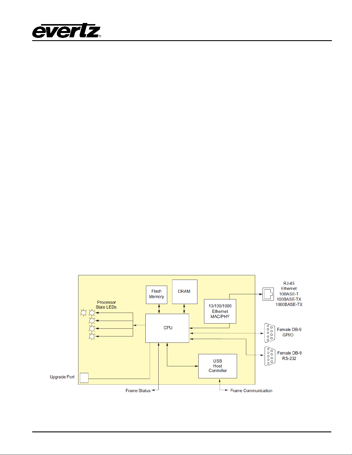
The 780 0FC VistaLI NK® Fram e Cont roller card provides a sing le point of ac cess to comm unicate wit h
VistaLINK
TX/1000BASE-TX Ethernet port and communication is facilitated using Simple Network Management
Protocol (SNMP ).
The 7800FC VistaLINK® Frame Controller handles all SNMP communications between the frame
(7 80 0 F R) and t h e n et w or k manag er (N MS ) , an d s er ves as a g at ew ay t o i n d i vi d ual card s i n t h e fr am e. Th e
7800FC VistaLINK
configurations.
Features:
• Complies with I EEE 802.3 10BASE-T, 100B A S E-TX and 1000BASE-TX E t hernet standards
• 1000Mb/s Gigabit Ethernet, 100Mb/s Fast Ethernet or 10Mb/s Ethernet dat a transfer, selected by
• Full-duplex or half-duplex op erati on, selected by auto-negotiation
• RJ-45 connector for network cable connection
• RS-232 s erial control port f or configuration
• Card edge L EDs indicate module fault, microprocessor state, acti vit y and link s tatu s
• Rear panel LEDs indicate Ethern et link, activity and speed
• Supports “ftp” upgrades for frame-wi de firmware upgrades (product specific)
• Includes VistaLINK
• Provid es frame/ chassis s tatus in form ation through VistaLI NK
• Provid es an onboard w eb interface to d irec tly control modules that support Web EASY
-capable modules. The 7800FC VistaLINK® Frame Controller provides a 1 0BASE -T/100BASE-
®
Frame Controller also provides an RS-232 serial port interface for customer
®
auto negotiat ion
PRO (VLPRO-C) module software configurati on tool
®
incl uding power supply status, frame
®
status , card insert ion/ removal c ounters, 7800 FC software version number and LE D c ontrol
®
Figure 1-1: 7800FC Block Diagram
Revision 1.0 Page-1
Page 8
7800 MultiFrame Manual
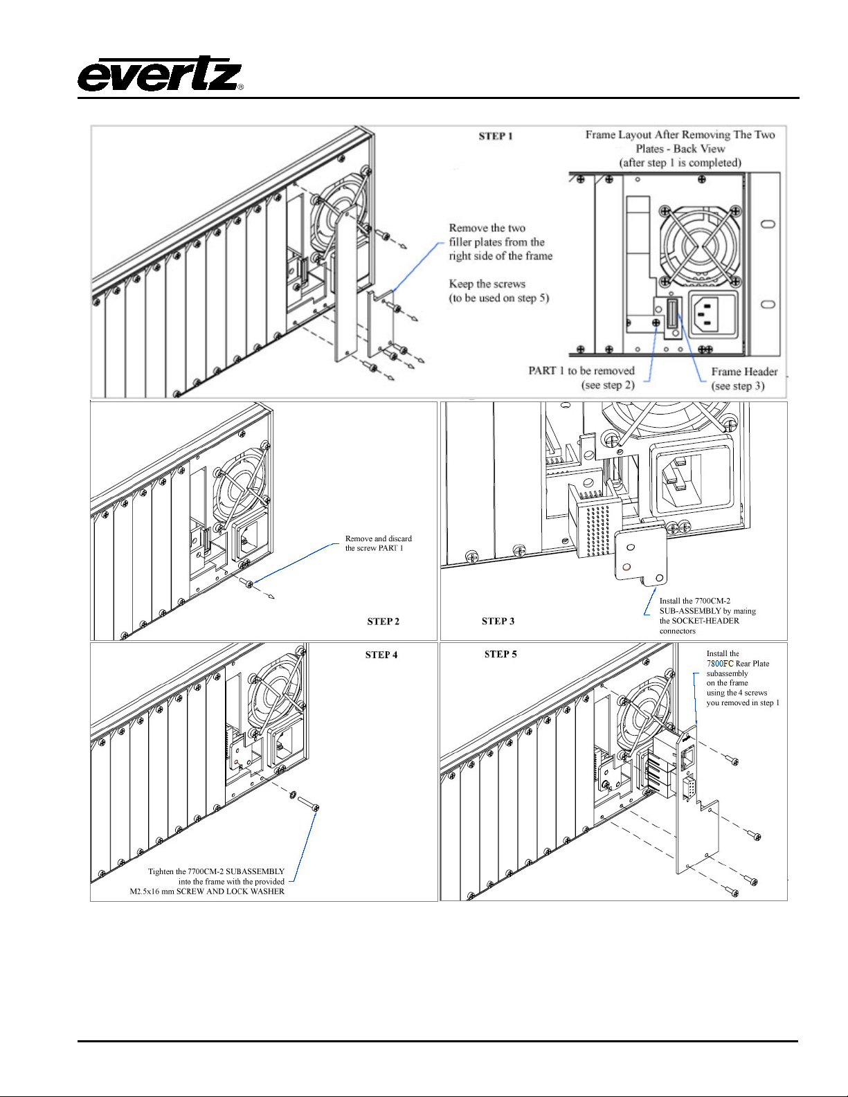
The 7800FC rear pan el ki t c onsi sts of a sc rew an d loc k
.
assembly with the M2.5x16 mm screw and M2.5
the plate to the extrusions using the mounting screws
the main module is installed.
7800FC VistaLINK® Frame Controller
2. INSTALLATION
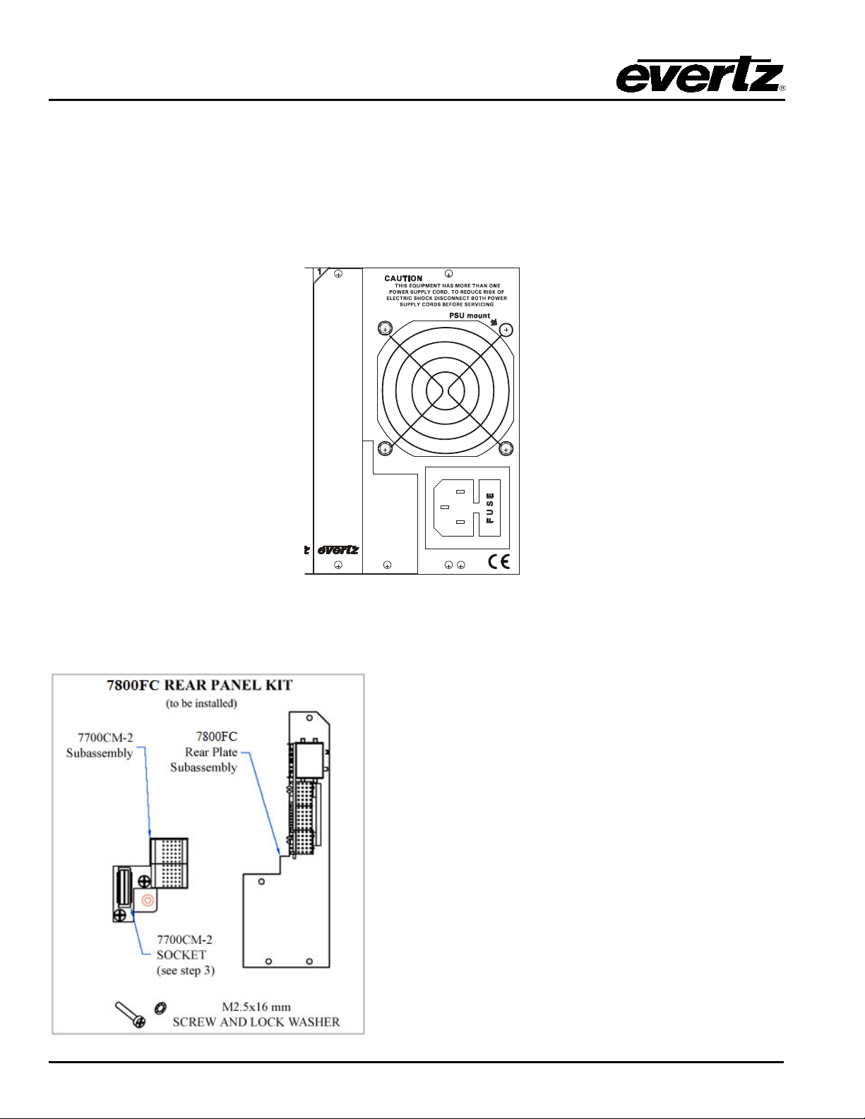
The 7800FC Frame Controller module can only be installed into 7700FR-C, 7800FR and 7800FR-QT
fram es th at h ave b een fi t ted wi t h t he p roper m odu le i nt erc onn ect c ir c ui t b oard. Thes e fram es have an ‘ L’
shap ed cover plate i nstalled, adjacent to the IE C power inl et connector as shown in Figure 2-1. If your
fram e d oes n ot h ave t hi s L s haped cover plat e th en th e 7800FC F r am e cont r ol l er c ar d c an not be i ns t al l ed
in this frame.
Figure 2-1: 7800FR Rear Panel with Cover Plate Installed
2.1. INST ALLING THE MODULE REAR PLAT E
washer, and two sub-assemblies, the 7700CM-2
connector module and the 7800FC rear panel plate
w hi c h h ou ses t h e app r opr i at e c on n ec t or s f or t h e m odu l e
To i nst all the 7800FC r ear panel ki t, l ocat e slot 1 at t he
right side of the frame’s rear panel. Remove the filler
plates from the slot as shown in s tep 1 of
Install the 7700CM-2 subassembly first. Remove the
screw PART 1 as shown in Step 2. Carefully al ign the
7700CM-2 soc k et w i t h t h e fr am e h ead er and pr ess fi rml y
into place as shown in step 3. Secure the 7700CM-2
sublock w asher as shown in Step 4.
Orient the 7800FC plate so that the labeling is visible
w hen t he pl ate is ins tall ed (s ee St ep 5). Loosel y fasten
Figure 2-2.
you r emoved i n S t ep 1 . Y ou w i l l t i gh t en th e sc r ew s after
Page-2 Revision 1.0
Page 9
7800 MultiFrame Manual
7800FC VistaLINK® Frame Controller
Figure 2-2: 7800FR Rear Panel Kit Installation
Revision 1.0 Page-3
Page 10

7800 MultiFrame Manual
7800FC VistaLINK® Frame Controller
2.2. INST ALLING AND REMOVING THE MODUL E
In or der t o in ser t or rem ove m odul es you w il l hav e t o open t h e fron t p anel . T ur n t he t w o cap t ive s cr ew s
located on the front panel counter clockwise several turns until they release completely from the front
extr usi ons . C arefu ll y l ow er t he fr ont pan el d oor so t hat t he fr ont edg e of t he d oor is l ower than the rear of
the door.
To ins tall the frame con trol ler module, orient the module vertically such that t he wh ite card ejector is on the
bottom. A lign the card with t he card guide c orresponding to the slot number where you installed the rear
panel plate. Carefully slide the module into the frame and press it completely into the rear panel
connec tors. Make sure that the connectors are ful ly seated in the rear pan el. When this is done, close the
front panel and then tighten the screws that hold the rear panel in place.
To r em ove t he fr am e con t roll er m od ul e, pres s t he c ard ejec t or dow n to r eleas e th e m odul e fr om th e back
pan el c onn ect ors . G ras p t he c ard usi ng th e c ard ej ec tor and pul l th e m odu le out from t he fram e. As th e
car d ej ec tor goes p ast th e fron t extr usi on, you wi l l h ave t o pul l it w it h s li ght l y m ore f orc e. Caref ul ly p lac e
the module in a safe place, free from static di s char ge.
Page-4 Revision 1.0
Page 11
2.3. REAR PANEL CONNECTIONS
7800 MultiFrame Manual
7800FC VistaLINK® Frame Controller
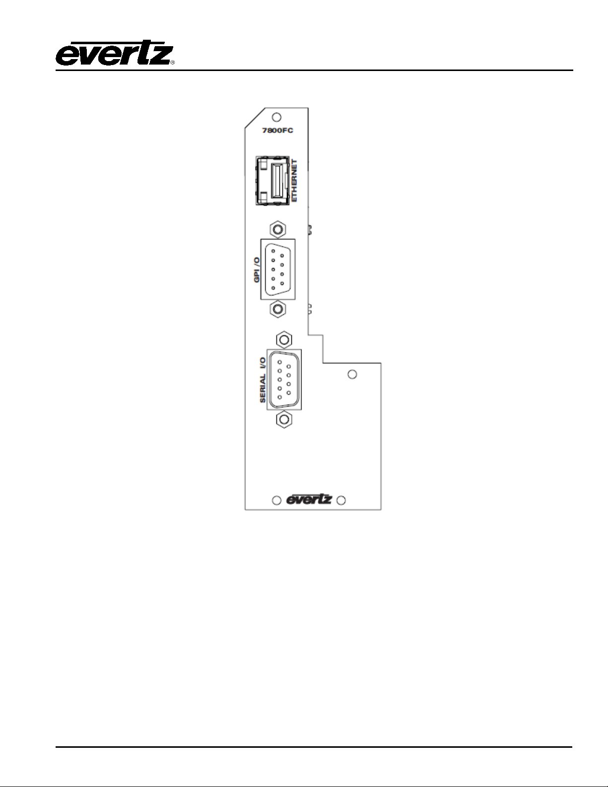
Figure 2-3: 7800FC Rear Panel
2.3.1. Ethernet Connection
The 7800FC i s designed to be used with either 10Base-T (10 Mbps), 100Base-TX (100 Mbps) al so known
as Fast Ethernet , or 1000B ase-TX (1000 MBps) tw i st ed pair Ethernet cabl i ng system s. When connecting
for 1 0B ase-T sys tem s , c at egory 3, 4, or 5 UT P c abl e as w el l as EI A /T IA – 568 100Ω ST P c ab l e m ay b e
used. W hen connecting for 100Base-T X sy stem s, cat egory 5 UTP cab le is req uir ed. W hen connec ting
for 1000Base-T system, category 5, 5e, 6, or 7 UTP cable is required. The cable must be “straightthrough” with a RJ-45 c onnec t or at eac h end (S ee Table 2-1). Mak e th e network connection by plugging
one end of the cable into the RJ-45 receptacle of the 7800FC and the other end into a port of the
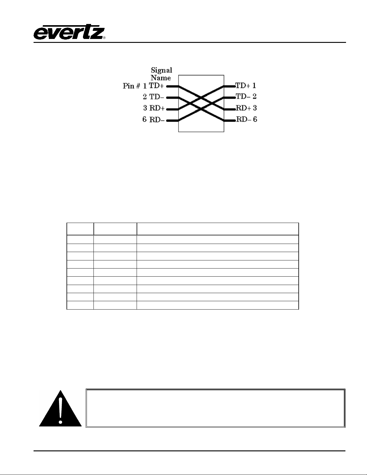
supporting hub. W hen connecting a 7800FC dir ect l y t o th e Et her net por t on a com p ut er you wi ll have to
use a “crossover” cable as shown in Figure 2-4.
Revision 1.0 Page-5
Page 12
7800 MultiFrame Manual
AT&T 258A or
EIA/TIA 568B
10BaseT
or 100BaseT
1
Transmit +
White/Green
White/Orange
X
2
Transmit –
Green /White or White
Oran ge/White or Or ange
X
3
Receive +
White/Orange
White/Green
X
4
N/A
Blue/White or Blue
Blue/White or Blue
Not used (required)
5
N/A
White/Blue
White/Blue
Not used (required)
6
Receive –
Oran ge/White or Or ange
Green /White or Green
X
7
N/A
White/Brown
White/Brown
Not used (required)
8
N/A
Brown/White or Brown
Brown/White or Brown
Not used (required)
7800FC VistaLINK® Frame Controller
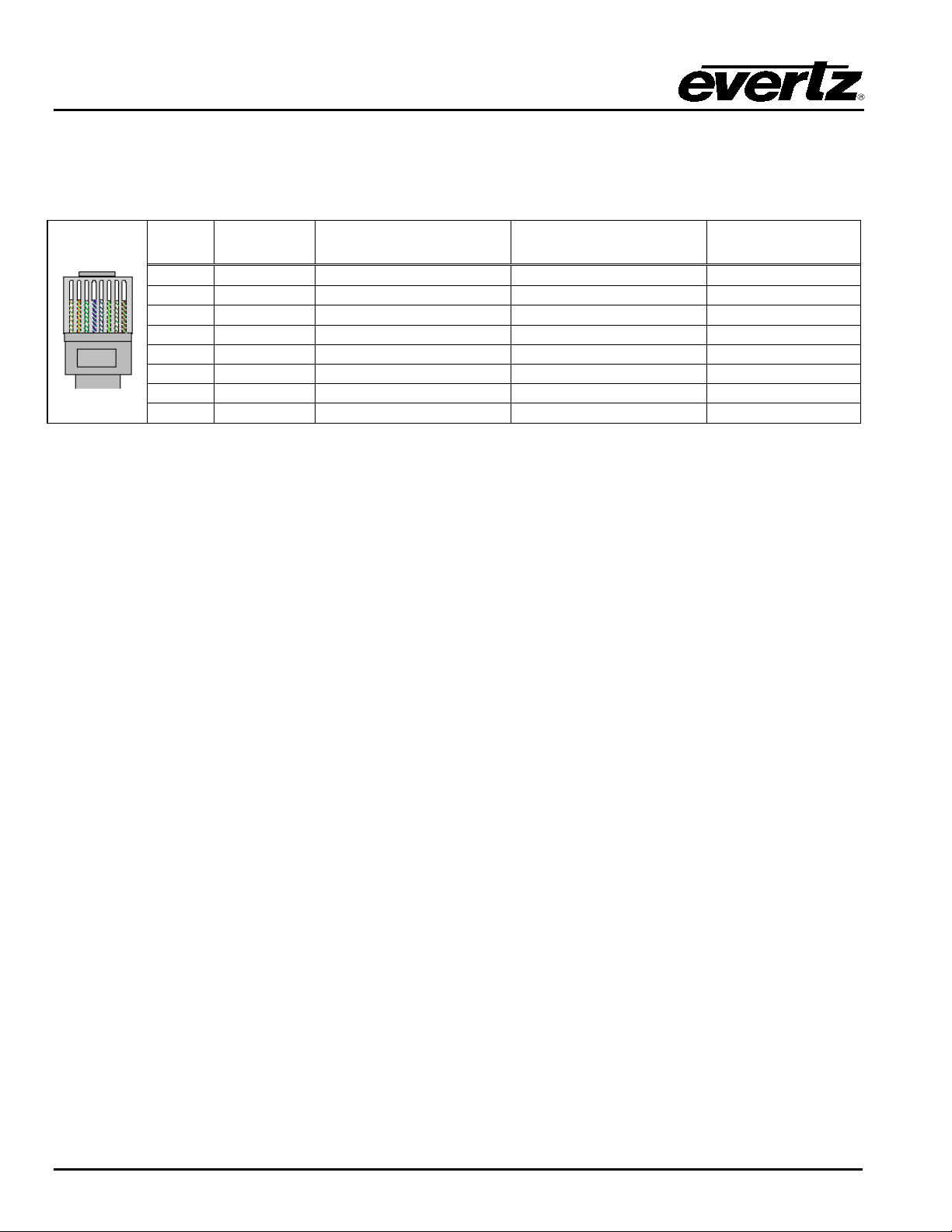
The straight-through RJ-45 cable can be purchased or can be constructed using t he pi nout inform ation in
Table 2-1. A colour code wiring table is provided in Table 2-1 for the c urren t RJ-45 standards (AT&T 258A
or EIA/TIA 258B colour coding shown). Also refer to the notes following the table for additional wiring
guide information.
Pin # Signal EIA/TIA 568A
Pin 1
Table 2-1: Standard RJ45 Wiring Colour Codes for “Straight Through” Cables
Note the following cabling information for this wi ring gui de:
• On ly t wo pai rs of wires are used in t he 8-pin RJ-45 connector to carry Et hernet sig nals
• Even though pins 4, 5, 7 and 8 are not used, it i s mandatory that they be present in t he cable
• 10Base-T, 100Base-TX and 1000B ase-TX use the same pins , a crossover cable mad e for one will also
w ork with the ot her
• Pairs may be solid col ours an d not have a st ripe
• Category 5 cable m ust use Cat egory 5 rated connectors
Th e maxi mu m c abl e run b etw een th e 7800FC and the supporting hub is 300 ft (100 m ). The maximum
combined cable run between any two end point s (i.e. 7800FC and P C/laptop via network hub) is 675 feet
(205 m).
Devices on the Ethernet network continually monitor the receive data path for activity as a means of
ch ecking that t he link is working correctly. W hen the network is idle, the devic es also send a li nk test
si gnal t o one an oth er t o veri fy li nk i nt egri t y. T he 7800FC rear pan el i s fi t t ed w i t h t wo LE D s t o moni t or t h e
Ethernet connecti on.
10/100/1000: This LED i s ON and am ber when a 1000Base-TX lin k is last detec ted . Thi s LED is ON
and green when a 100Base-TX link is last det ected. The LED is OFF when a 10Base-T
link is last detected (the LINK LED is ON). Upon power-up the LED is OFF as the last
det ec t ed r at e i s n ot k nown an d t h er efor e d efau l t s to th e 1 0B as e-T state u n t i l rate det ec t i on
is completed.
LN/ACT: This dual purpose Green LED indic ates that the 7800FC h as es t abl i s h ed a v al i d l i nk age to
its hub, w hether the 7800FC is sending or receiving data. This LED wi ll be ON when the
7800FC has established a good link to its supporting hub. This gives you a good indication
that the segment is wired correctly. The LED wil l BLINK when the 7800FC is sending or
receiving d ata. The LED w ill be OFF if there is no valid conn ection.
Page-6 Revision 1.0
Page 13
7800 MultiFrame Manual
1
GND
Chassis ground
2
Tx
RS-232 Transmit Output
3
Rx
RS-232 Receive Input
4
5 Sig Gnd
RS-232 Signal Ground
6
7 RTS
RS-232 RTS Input
8
CTS
RS-232 CTS Output
9
7800FC VistaLINK® Frame Controller
If you are b uilding a “crossover ” cab le you must wire it according to Figure 2-4:
Figure 2-4: Crossover Cable Wiring Diagram
2.3.2. GPI/O Connections GP I/O: A 9 pin female ‘D’ connector for c onnec tion to exter nal dev ices . (Currenlty this port is not used. )
2.3.3. Serial I/O Connections SE RIAL I/O: A 9 pin female 'D' c onnec tor for connection t o a computer. (Currentl y this port is not used.)
Pin # Name Description
Table 2-2: S e r ia l I/O Connector Pin D e f in it ion s
2.4. REPLACING THE BATT ERY
The Frame Controller is fitt ed w ith a 3V Li thium batt ery type CR2032. This battery is used to power nonvolatile memory of some of the frame controller’s param eters w hile power is rem oved from the fram e.
Bef ore attempting to chan ge the battery remove p ower from the 7800FC card.
Revision 1.0 Page-7
CAUTION
Danger of explosion if battery is incorrectly replaced.
Replace only with the same or equivalent type.
Page 14

7800 MultiFrame Manual
7800FC VistaLINK® Frame Controller
CAUTION
Danger of explosion if battery is exposed to excessive heat such as direct
sunlight, fire, etc.
2.4.1. Safety Guidelines and Precautions Concer n ing th e Use of 3V Lithium Batteries
Pl eas e ob ser ve t h e f ol lowin g w ar ni n g s s t r i ctl y. I f mi sused, the batteries may explode or leak, causing injury
or d amage to th e equipment.
• The batteries must b e inserted into the equipment with the correct polarity (+ and -)
• Do not attem pt to revive used batteries by heating , charging or other means
• Do not dispose of batteries in fire. Do not dismantle batter ies
• Do not short circuit batteries
• Do not expose batt eries to high temperatures, moisture or di rect sunlight
• Do not place batter ies on a conductive surface (anti-stati c work m at, packaging bag or form trays)
as i t can cause the batt ery to s hort
Page-8 Revision 1.0
Page 15

3. SPECIFICATIONS
3.1. ETHERNET Network Typ e: IEEE 802.3 (10BASE-T)
IEEE 802.3u (100BASE-TX)
IEEE 802.3ab (1000BASE-TX)
Connector: RJ-45
3.2. SE RIAL I/O Standard: RS-232
Connector: Female DB-9
Baud Rate: 115,200
Format: 8 bits, no parity, 2 stop bits, no flow control
3.3. ELECTRICAL Voltage: + 12VDC
Power: 8 Watts
EMI/RFI: Compl ies w ith FCC Part 15
Cl ass A and EU EMC d irec tiv e
7800 MultiFrame Manual
7800FC VistaLINK® Frame Controller
3.4. PHYSICAL (NUMBER OF S L OTS) 350FR: 1
7700FR-C: 1
7800FR: 1
Revision 1.0 Page-9
Page 16
7800 MultiFrame Manual
78
00FC
Shaft
Encoder
Module OK
LED
Status Display
USB Port
Serial Upgrade
Port
Diagnostic
LEDs
1
2
3
Local Fault
LED
7800FC VistaLINK® Frame Controller
4. STATUS INDICATORS
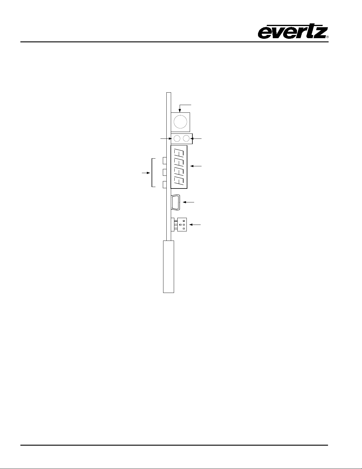
The 7800FC has 5 L ED Status indicators on the f ront card edge to show operational status of the c ard at a
glance. Figure 4-1 shows t he location of the LEDs and card edge controls.
Figure 4-1: 7800FC Status LED Location
4.1. MODULE STATUS LEDS
Two lar ge LEDS on the fr ont of the main board indi cate the general health of the module:
LOCAL FAULT: Th i s R ed LE D i n d icates p oor modu l e h eal t h or i f a l ocal in p ut power fau lt exists (i.e.:
a blown fuse). The LOCAL FAULT indication can also be reported to the frame
through the FRAME STATUS j umper.
MODULE OK: This Green LED indicates good m odule health. I t wil l be ON when the board pow er
is good.
The remaining LEDs have no functionality at this time.
Page-10 Revision 1.0
Page 17

7800 MultiFrame Manual
7800FC VistaLINK® Frame Controller
4.2. DOT-MAT RIX DISPLAY
Ad dit ion al si gnal stat us m oni tori ng of the c ard’ s par amet ers i s provi ded vi a the 4-c har act er al ph anu m eri c
status disp lay located on the card edge.
W hen the card is initially inserted, it will display the m essage BOOT an d t hen th e m essag e EXEC. This
indicates that the 7800FC is running through its bootup sequence and executing the application code.
On ce the applic ation code is completely load ed and r eady to u se, i t will display the message FC.
If the shaft encod er i s pressed in, the display will cycl e through the firmware version and the IP address of
the 7800FC.
Revision 1.0 Page-11
Page 18
7800 MultiFrame Manual
MODULE STATUS
+12V
UPGRADE
J4
J9
J8
ON
EVERTZ (1) 7800FC
GND
OFF
BUS
RUN
7800FC VistaLINK® Frame Controller
5. JUMPERS
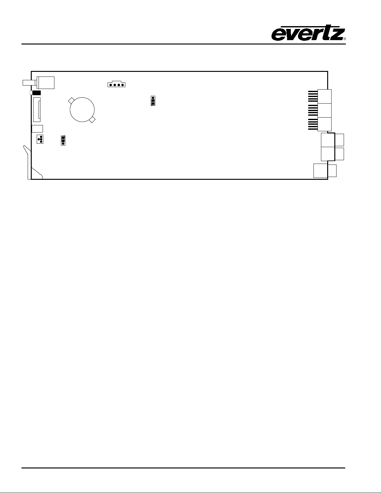
Figure 5-1: Location of Jumpers
5.1. SELECTING WHETHER LOCAL FAUL TS WILL BE MONITORED BY THE GLOBAL FRAME ST ATUS
BUS: The BUS jumper J8 loc ated near the top m iddle of the module determines whether loc al
faults (as shown by the Local Fault indicator) will be connected to the 7700FR-C, 7800FR
or 7800FR-QT frame's global status bus.
To monitor faults on this module with the fram e status indicators (on the Power Supply
FRAME STATUS LEDs and on the F rame's Fault Tally output) install thi s jumper in the On
position. (Default)
When this jumper is installed in the Off position, local faults on this module will not be
monitored.
5.2. CONFIGURING THE MODULE F OR FIRMWARE UPGRADES
UPGRADE: T he UPGRADE jum per J4 loc at ed beh in d t he s eri al p ort head er J 9 is us ed w hen fir m war e
up grad es are b ein g done to t h e m odul e. For norm al oper ati on it should be installed in the
RUN pos ition. See th e Upgrading F i rmware section 7 for more in formation.
Page-12 Revision 1.0
Page 19

7800 MultiFrame Manual
7800FC End
PC En d
2 row X
3 pin Berg
9 pin D
Female
Key
1
Blue
1 Rx
2
Green
Tx 2 Tx
3
Yellow
Rx
3
Tx Gnd
4
Orange
Gnd
5
Key 5 Red
---
6
Brown
Baud
115200
Data bits
8
Parity
no
Stop bits
2
Flow C ontrol
no
7800FC VistaLINK® Frame Controller
6. CONFIGURING THE FRAME CONTROLLER
The 7800FC Fram e Con trol ler i s con fig ured by c onnec ti ng i ts ser ial port to a c omp uter r unning a readily
avai labl e ter mi nal prog ram suc h as Hy perT erm inal . T he foll owi ng p roc edure w il l gu ide y ou th roug h each
step of t he configuration pr ocess.
You will need the fol l owing equipment in order to configure the 7800FC Frame Controller:
• PC wi th available communications port. Th e com munication speed is 115200 baud
• “Straight-thru” serial ext ension cable (DB 9 fem ale to D B9 male) or (DB 25 female to DB9 male)
• Ter mi nal program such as H yperTerm inal
• Special upgrade cable supplied with the 7700FR-C, 7800FR or 7800FR-QT frame. This cable is
normally in the vinyl pouch at the front of this manual. (E vertz part #WA S76).
6.1. ESTABLIS HING COMMUNICATION WITH THE FRAME CONTROLLER
6.1.1. Connecting the Computer to the Card Edge Serial Port
Connect the supplied serial upgrade c abl e to the 2 x3 header (J 9) at t he fron t ed ge of t he 7800FC card.
Note that pins 1 and 5 on the header should be removed and pins 1 and 5 on the c able c onnec tor should
also be plugged. If the cabl e is not keyed, m ake sure that you install i t so t hat the c able i s towards the front
of t he fr am e w hen t he m od ul e is in st all ed ( i. e. so t hat it pas ses ov er t he c ard ejec t or). Pin 1 of the ribbon
cable is brown and will be facing the bottom ejector side of the module when the cable is correctly
installed.
Pin
Table 6-1: 7700 Upgrade Cab le (WA-S76)
6.1.2. Terminal Program Setup
6 Conductor
Ribbon Cable
Pin
1. S tart the terminal program and confi gure the port settings of the t erminal program as f ollows:
Table 6-2: Port Settings of the Term inal Program
Revision 1.0 Page-13
Page 20

7800 MultiFrame Manual
Kernel Build Date : Jan 28, 2013
login:
**** Main Menu ****
>
7800FC VistaLINK® Frame Controller
2. Install the 7800FC card int o th e fram e. A fter the c ard p ower s up an d th e boot -up m essag es are
finished, a “login” prompt will appear in the terminal window. (For future reference 7800FC
software version information is displayed prior to the “logi n” prom pt and should be quoted t o Service
staff when required.)
For example:
Software : v1.2 Build 2
Tag : 7801FC_r1-2-2
Software Build Date : Jan 30, 2013
Wed Jan 30 11:05:46 GMT 2013
NetBSD/evbppc (780xfc) (console)
3. I f the prompt does not appear, the following is a list of possible reason s for fai led commun ication s :
• Defective Serial Upgrade cab le.
• Wrong communications port selec ted i n the termin al program.
• Improper port settings in t he termi nal program. ( Refer to step 1 for set tin gs).
4. At the “l ogin” prompt , enter:
• “customer” for user name <Enter>
• “customer” for password <En ter>
NOTE - Neither username n or password can be modified at the time of this manual
revision release.
5. A menu for Networ k, SNMP and FC Upgrade Set up Configuration appears and is detailed in the
next section.
6.2. CONFIGURING THE NET WORK SE TTINGS
Fr om main menu, three selections are avai lable - Net work Setup, SNMP Setup.
• Network S etup is used t o set network IP addr esses as well as broadcastin g and routing i nstruction s
• SNMP Setup is used to ident i fy up to ten t rap destin ation IP addresses.
<1> Network Setup
<2> SNMP Setup
<X> Exit
<W> Exit without saving to flash
Page-14 Revision 1.0
Page 21

7800 MultiFrame Manual
**** Network Setup ****
>
7800FC VistaLINK® Frame Controller
To c h oose on e of t he menu c h oi c es , enter t h e letter or nu mber sh ow n on t he l ef t an d then pr ess < E n t er> .
If you c h oose m enu it em 1 or 2 or 3 you w i l l be p res en t ed w i th an ad d i t i onal menu . C h oose menu i t ems
on these sub menus in t he sam e way or press X to return to th e main menu.
6.2.1. Network Setup
The Network Set up men u has si x n et w or k par ameter s that n eed to be c on fi g ur ed . If th e net w or k is us i n g a
DHCP server , s et t he DHCP param et er to yes b efore p roc eedi ng to c h ange t h e oth er par am et ers. W h en
the DHCP setting is set to yes, the IP Address, Netmask, Gateway, and Broadcast addresses are
automaticall y assigned an d their c orresp onding m enu item s are di sabled.
If t h e net work i s n ot u si n g a DH C P serv er, set th e DHCP parameter to No before proceeding t o change the
IP Address , Netmask, Gateway, and Broadcast addresses.
The foll owing screen displays the network settings on the 7800FC fr ame controller.
(1) Use DHCP [N]
(2) Hostname [fc-default]
(3) IP Address [192.168.1.187]
(4) Netmask [255.255.255.0]
(5) Gateway [192.168.1.1]
(6) Broadcast [192.168.1.255]
(7) Use Telnet [N]
(X) Exit
The DHCP mode should be disabled before proceeding with the 7800FC Frame
Controller upgrade, which is outlined in section 7.3.7. In order to successfully
upgrade the device, select No [N] when prompted for DHCP m ode, as shown in
the above network setup screen. If the DHCP is enabled you will be unable to
proceed further with the upgrade. See section 7.3.7 for instructions on upgrading
the 7800FC Fr am e Controller.
The chart below gives a brief descript ion of each menu item and what the parameter does. To choose one
of the menu choic es, ent er the l ett er or n um ber sh own on th e left and t hen p ress < Ent er> . You wi ll be
pr ompted to enter the required parameter value. When you are done con f iguring the Net work Setup menu
item s press X to r et u rn t o the m ai n menu . I f you are u n c l ear abou t h ow t o confi g u r e you r n et work, con su l t
your network administrator.
Revision 1.0 Page-15
Page 22

7800 MultiFrame Manual
within the network.
192.168.1.XXX is an example of an IP address in a private (internal) network. If
controller local subnet that was
Frame Controller Parameters
IP Address
Hostname
IP Address
Netmask
Gateway
Broadcast
7800FC VistaLINK® Frame Controller
Th i s s et t i n g al l ow s t h e F rame Con t r ol l er t o be automatically assigned an IP ad dr es s
Use DHCP
for t h e p ar am et er s below from a DH CP serv er d u r i ng b oot -up. If you are not runni ng
a D HCP server , set th is p aram eter t o “No” firs t bef ore m akin g any c hang es to ot her
parameters.
Hostname
IP Address
Netmask
Gateway
Broadcast
Use Telnet
A user-configurable 7800FC identifier. This menu item can be used to name the
specif ic frame, serv ice or location of the 7800FC.
This control sets the unique IP address of the 7800FC
con nec t in g m ul ti pl e fram es (eac h w i th it s ow n f ram e c ont rol ler ), t ake c are not t o use
the sam e IP address for eac h.
This m enu item def ines the “subnet mask” of the networ k . Speci fic ally, th is par ameter
out l i n es al l t h e I P ad d res ses t h at c an c omm u n i c at e w i t h t h e 7800FC. T h i s par ameter
can be set t o 255.255. 255. 0 for a private network.
This item identifies the IP address of the “gateway” (in previous versions of the
soft war e, “g atew ay” i s refer red t o as “route”) . I n it s si mp lest sense t he gat eway is a
device that routes packets to different networks. If configured , the IP address
of the gateway must reside in the frame
defined by th e subnet mask. I n a pr iv ate n etw or k, th is gat eway cou ld be i den ti fi ed
as 192.168.1.1. Power cycle required after gateway change.
This m enu item sets t he “broadcast” I P address. For example, i n a pri vate n etw ork
with a subnet mask configured as 255.255.255.0. This param eter c an be set to
192.168.1.255
Th is set ti ng all ow s t he F ram e Con tr oll er to b e ac c es sed t h rou g h a t el n et i n t er fac e f or
config uration chang es instead of just the serial interface.
To communicate beyond the private (internal) network and into the internet, all
messages must be relayed via the gatew ay (firewall). As a result, the firew all must
For c on ven i en c e an d f uture r ef eren c e, a chart is pr ov i ded b el ow t o r ec or d I P configuration for this SNMP
networ k . (Addi tional blank charts have also been added at t he end of this manual.)
Once the Network Setup paramet ers have b een configured, exit t he Network Setup by pressing X then
<Enter>. Proceed to the SNMP Setup menu option by entering 2 then <Enter> at the Main Menu
prompt.
Page-16 Revision 1.0
be configured separately by the end-user to facilitate communication. Consult
your network administrator if establishing a communication link beyond the private
network.
Page 23
7800FC VistaLINK® Frame Controller
changed, the manager must have the identical settings. Otherwise no
changed, the manager must have the identical settings. Otherwise no
6.2.2. SNMP Setup
In the SNMP Setup men u, there are three submenus to c hoose from:
7800 MultiFrame Manual
SNMP V1 Setup
SNMP V3 Setup
SNMP Version
Setup
6.2.2.1. SNMP V1 Setup
In the SNMP V1 Setup menu, th ree parameters are configured :
Read
Community
String
Read/Write
Community
String
This menu item contains setup information for SNMP version 1 related
configurations.
This menu item contains setup information for SNMP version 3 related
configurations.
This menu item identifies which of the two version of SNMP will be used to
communicate to the 7800FC.
Factory default “public” (No changes required. However, if these settings are
communication will occur betw een the 7800FC and the manager.)
Factory default “private” (No changes required. However, if these settings are
communication will occur betw een the 7800FC and the manager.)
Th i s menu i t em id en t i fi es t h e des t i n at i on I P ad dr ess es (S NMP Trap Handlers) to
Trap Setup
Once the SNMP V1 Setup param eters have b een configured, exit SNMP V1 Setup by pressing X then
<Enter>.
6.2.2.2. Community Strings
Community Strings are considered as “passwords” within SNMP, controlling the ability to read (“GET”)
and/or read/write (“SET”) values to a specific destination. “GET” and “SET” messages include the
comm unit y strings w ithin t heir PDU (protocol data units). B y factory d ef ault , community strings are set to
“public” and “private”, respec tively. If these set tings are changed, the SNMP manager’ s comm unity string
must agree with the “SET” string. Otherwise no communication will occur between the 7800FC and
manager.
which TRAPS are sent via SNMP. A maximum of ten IP addresses may be
entered.
Revision 1.0 Page-17
Page 24

7800 MultiFrame Manual
>
This menu item is used to set Trap configuration parameters including Add,
7800FC VistaLINK® Frame Controller
For example:
**** SNMP Setup ****
<1> Read Community String [public]
<2> Read/Write Community String [private]
<3> Trap Setup
<X> Exit
6.2.2.3. T rap S etu p
“Tr ap Set up” allow s t he user to define IP ad dres ses of the trap listeners for wh en the asynchronous
fault messages are sent. A maximum of ten IP ad dr esses c an b e st ored in th e Fr am e Cont r oll er. Af ter
sel ecting “Add…” or “Rem ove…” I P addresses ar e entered one at a time.
Add Trap
Destinations
Add a SNMP trap server IP address to the TRAP distribution list.
Remove a S NMP trap server IP address from the TRAP di st ribution list. For
exam ple, selec tin g th is option reveals the l ist of IP address es wi th the pr ompt to
Remove Trap
Destinations
remove one f rom the l ist:
Trap #1: 192.168.1.76
Trap #2: 192.168.8.140
Remove t r ap # > 2
Di splay s a list of all entered SNMP trap server IP addresses. For example:
Show All T rap
Destinations
Trap #1: 192.168.1.76
Trap #2: 192.168.8.140
Trap #3: 192.168.8.112
Once the SNMP V1 Setup param eters have b een configured, exit t he SNMP Setup by pressing X then
<Enter>.
6.2.2.4. SNMP V3 Setup
In SNMP V3 Setup menu, th ere are two submenus to choos e from :
SNMP V3
User Setup
This m enu it em is used to set User configuration param eters including Add, Edit,
Remove and Show users
SNMP V3
Trap Setup
Remove, and Show traps
Once the SNMP V3 Setup param eters have b een configured, exit SNMP V3 Setup by pressing X then
<Enter>.
Page-18 Revision 1.0
Page 25

7800 MultiFrame Manual
User Name
This is mandatory.
User Type
Default is READONLY, Options are READONLY, READWRITE
Authentication
Default is NONE. O ptions are NONE, MD5, or SHA-1.
Authentication
If Authentication is not set to NONE then this field is mandatory,
Use Privacy
Default is NONE, O ptions are NONE, AES, or DES. Use Privacy will
Encryption
If Use Privacy is not set to NONE then th is field is mandatory,
Included OID 1
These op tions are optional. They define the OID tree that the user is
Included OID 2
Included OID 3
7800FC VistaLINK® Frame Controller
6.2.2.4.1. SNMP V3 User Setup
The SNMP V3 User Setup menu defines basic access rules for the S NMP V 3 prot ocol, cont rolling the
ability to read (“GET”) or read/write (“SET”) parameters. It also provides the password key for
authentication as well as AES or DES encrypti on. A maximum of ten different users c an be entered.
Add New User and Edit User wil l provide the same in terface.
Add New Us er
This defines the access mode for the specific user.
Au thenti cation to check integrity of t he incoming messages.
Password
otherwise, Authentication will be automatic al ly set back to NONE.
The password m ust be at least 8 char acters long.
encrypt incoming and outgoing messages.
Edit Us er
otherwise, Use Privacy will be automaticall y s et back t o N ONE. The
password must be at least 8 c haracters l ong.
restricted to access. The user can not ac cess any other OID that is
not listed or included in the OID tr ee specified.
Remove User
Show All
SnmpV3 User
Password
Rem oves previous ly ent ered users. This will affect the SNMP V3 Trap setup as
w ell. Please refer to next section for details.
Lists all entered users. It will show username, access type, authentication type
and password, privacy type and password as well as i ncluded OIDs.
On c e t h e SNMP V3 Us er Setup paramet ers h ave b een confi gured, exit SNMP V 3 Us er Setup by pressing
X then <Enter>.
Revision 1.0 Page-19
Page 26

7800 MultiFrame Manual
Enter T r ap Destination
Address
En ter IP address all at once
Enter T r ap Destination User
En ter User Name only. Input is r equired to match
**** Main Menu ****
login:
7800FC VistaLINK® Frame Controller
6.2.2.4.2. SNMP V3 Trap Setup
The SNMP V3 Trap Setup m enu all ow s t he us er t o define I P ad dr esses of the trap listeners for wh en
the asynchronous fault messages are sent. A maximum of ten IP addresses can be stored in the
Fr am e Con t roll er. Th e di ffer ent b etw een S NMP V 1 T rap and SN MP v 3 T rap i s t hat S NMP V 3 req ui res a
matchi ng User, whi ch is creat ed in the previous sec t i on.
Add Tr ap destination such that Fr ame Con trol ler will send fault messages to
specif ied address.
Add New V3
Trap Destination
Note: I f user is deleted af ter trap informat ion i s created, thi s trap inf ormation is not
val id and Frame Con trol ler w ill not s end fault message to that IP ad dress.
one of User s created in previous section
Remove V3 Trap
Destination
Show All
SnmpV3 Trap
Destinations
On c e t h e SNMP V3 Trap S etup paramet ers hav e b een confi g u red , exi t S NMP V 3 Trap Setup by pressing
X then <Enter>.
6.2.3. Exiting the Setup Menu
From the Main Menu, press X to sav e t h e con f igurati on to mem ory. After 30 seconds, a successfu l save of
the configuration is ac know ledged w ith a “Com mi t succ essfu l” stat em ent , and t he us er i s ret ur ned to t he
“login” prompt.
For example: (after pressing X<enter>)
<1> Network Setup
<2> SNMP Setup
<X> Exit
<W> Exit without saving to flash
X
Please wait 30 seconds to save settings to flash…
Commit successful.
NetBSD/evertz <fc-default>
Removes p reviously entered trap inf ormation .
Lists all entered trap information. It will show destination IP address and trap
User.
Press W if you made an error during configurat ion and want to exit the setup menu wit hout saving the new
settings. In either case you w i l l return to the “login:” prompt.
Page-20 Revision 1.0
Page 27

7800 MultiFrame Manual
**** Main Menu ****
login:
7800FC VistaLINK® Frame Controller
<1> Network Setup
<2> SNMP Setup
<X> Exit
<W> Exit without saving to flash
W
NetBSD/evbppc (780xfc) (console)
At this point, the serial con nect or can be rem oved from the Fram e Controller and t he termi nal program
closed. An SNMP manager using the previously specified IP can now be initiated.
Revision 1.0 Page-21
Page 28

7800 MultiFrame Manual
7800FC VistaLINK® Frame Controller
7. UPGRADING THE FRAME CONTROLLER IMAGE VISTALINK®
7.1. PROCEDURES FOR UPGRADING THE F RAME CONTROLLER IMAGE VISTALINK®
The 7800FC Fram e C ont rol ler fac il it at es c om m uni c ati on b et ween th e SN MP -enabl ed ( Vi st aLI NK®) cards,
resi di ng in a fram e an d t he S NM P Man ager (Vi st aLI NK
to be upgraded wit h the l atest inf ormation (“image” ) to maintain the most up-to-date monitor ing and control
capabilities.
The 7800FC Fram e Cont rol l er i m age can be u pg raded by tw o di ffer ent pr oced ur es, wh ic h are out l in ed i n
sections 7.2 and 7.3.
P RO). F r om ti me t o t i me, t h e 7 80 0 F C wil l n eed
®
7.2. REMOTE UPGRADE PROCEDURE US ING VistaLINK
To perfor m the rem ote up grad e for t he 7800FC VistaLINK
setup:
• A working install of a VistaLINK
• A downloaded and unzipped FC image file (.bin file) from
The DHCP mode should be disabled before proceeding with the 7800FC Frame
Controller upgrade. T o disable your DHCP refer to section 6.2.1.
7.2.1. Downloading the 7800FC Frame Controller Image
1. Download the image file “7800FC Image File” from the Evertz web site (
Downloads > Firmware Downloads link > Type “7800FC” in the Model search and press “Go”).
Save the f ile to the hard drive.
2. Unzi p t he d ow nl oaded f il e and st ore t he . bi n fi l e in a selec t ed su b-di r ec t or y. Rec or d t h e l oc ation of
the stored file.
P ro cl ient or VLPRO-C that’s version 10.0.7 or greater.
®
®
Fr ame C ontr oller you w il l need the fol low in g
®
http://www.evertz.com
www.evertz.com –
Page-22 Revision 1.0
Page 29
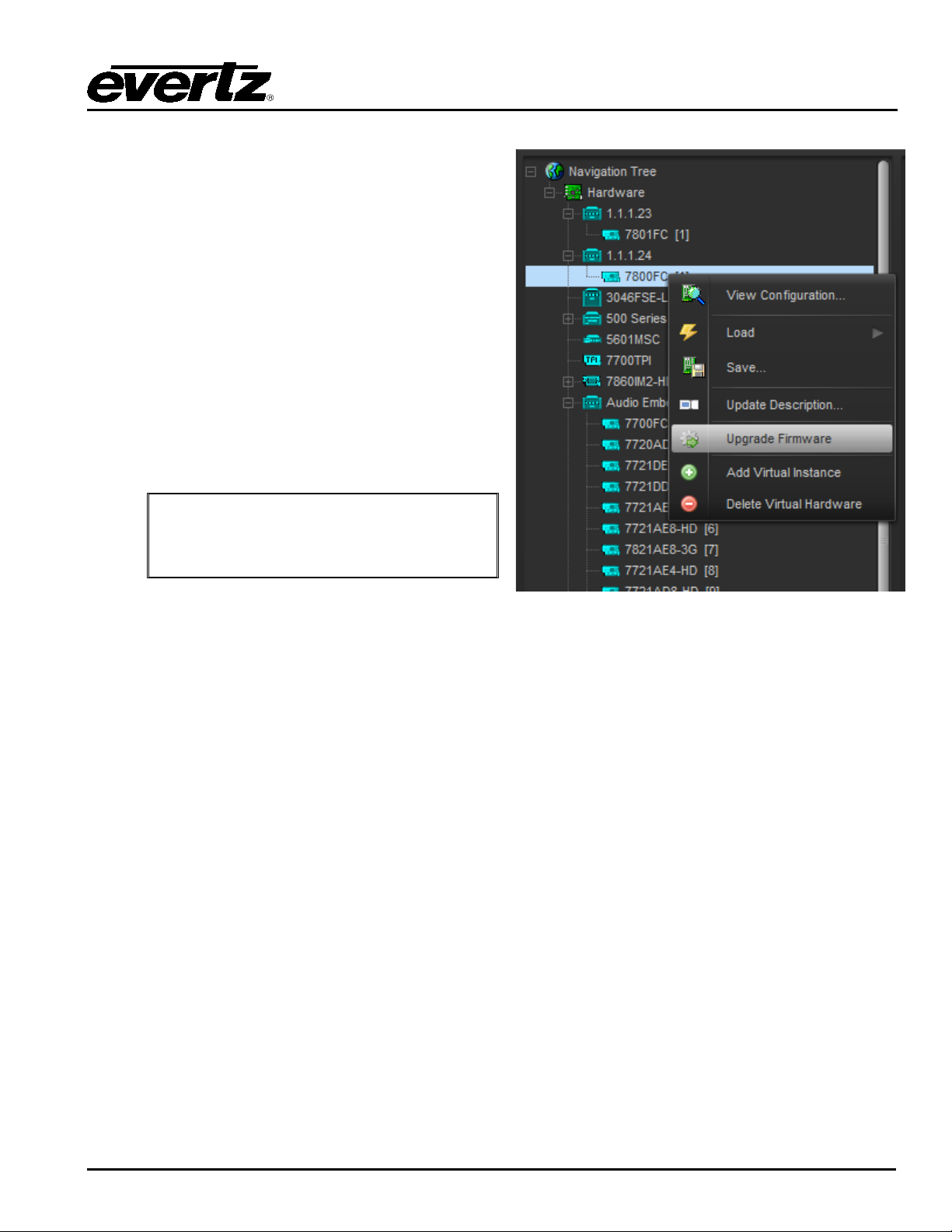
7.2.2. Upgrading the Frame Controller Image using VistaLINK®
1. Start a VistaLINK® PRO client and login using the
C does not
in the hardware tree using
Click the ‘Browse’ button to select the unzipped
Image .bin file, which was downloaded in
Click the Upgrade button and w ait for the upload to
ely 5 to 10
automatically and return online in normal “run”
mode.
Administrator user account (VLPROuse login accounts).
2. Expose the 7800FC
‘Add/Update Frame’ and collapsing the nodes in the
tree appr opriately.
3. Use t h e right-cli ck mouse button on the ‘7800FC’ in
the tree and sel ect ‘View Config uration…’ opt ion.
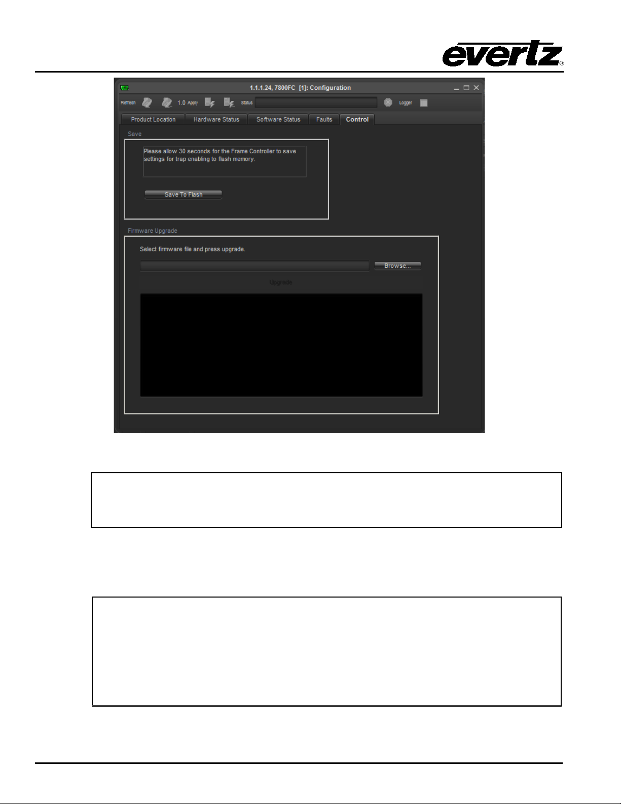
4. Select the ‘Control’ tab in t he configu rati on view.
5.
7800FC
section 7.2.1.
When upgrading the FC Image file,
ensure that you select the extracted
.bin file and NOT the entire .zip file ,
7800 MultiFrame Manual
7800FC VistaLINK® Frame Controller
6.
complete. This will take approximat
minutes depending on network traffic .
7. Upon completion, the 7800FC module will reboot
Figure 7-1: FC shown in the Hardware Tree
Revision 1.0 Page-23
Page 30
7800 MultiFrame Manual
7800FC VistaLINK® Frame Controller
Figure 7-2: Control Tab for the FC Configuration View
If for any reason the upload is interrupted, you must execute the procedures
7.3. SERIAL CARD EDGE UPGRADE PROCEDURE
The 7800FC Frame Control l er image is upgraded by following the procedure outlined in this secti on.
outlined in sections 7.3.4, 7.3.5 and 7.3.7, as you w ill be unable to complete the
procedure outlined in section 7.2.
Throughout the upgrade instructions, when you are prompted to type commands
using HyperTerminal, the following conventions apply.
Do not type the quotation marks “”
<space> means to press the space b ar
<Enter> m eans to press the “Enter” key
<Ctrl-x> means to press and hold the “ Ctrl” key and p ress th e “ x” key
Page-24 Revision 1.0
Page 31

7800 MultiFrame Manual
Evertz NAND PPCBoot et.816
PPCBOOT>
7800FC VistaLINK® Frame Controller
7.3.1. Downloading Upgrade Files
1. Download the boot loader “7800FC Boot Loader”, upgrade program “7800FC Upgrade” and the
image file ”7800FC Image File” from the web site (
Dow nload s li nk > Typ e “7800FC” i n th e Model sear ch and pr ess “ Go”. ). S ave t he fi l es t o th e hard
drive.
2. Unzi p t he dow nload ed fi les and stor e them i n a sel ect ed sub -dir ect ory . R ecor d t he l oc ati on of th e
stored files.
7.3.2. Linking the Frame Controller to th e Network Adapter
Con nec t a “ st rai ght -thru” Cat5 Ethernet c abl e wi t h RJ -45 c onnec t ors , b etw een t h e P C’ s n et w or k E thern et
card and a network hub; and a second “straight-thru” Cat5 Ethernet c abl e b etw een t he h ub and th e rear
plate of the 7800FC VistaLINK
Frame Controller. A “cross-over” cable directly connecting the PC’s
®
Et hern et ad apter to t he 7800FC Fram e Con tr oll er’ s rear pl ate c an be s ub st it ut ed f or t he t wo s tr aig ht -thru
Ethernet cables and hu b. (See sec tion 2.3.1)
7.3.3. Connecting the Computer to the Card Edge Serial Port
Refer to section 2.3.2 for instructions on connecting the computer to the card edge serial port and
config uring the termi nal software.
www.evertz.com – Downloads > Firmware
7.3.4. Setting the 7800FC Frame Controller to Upgrade Mode
The UPGRADE jumper J9 l ocat ed at t he fr ont of t he m odu le is used w hen “im age” u pgr ades are being
don e t o t h e 7800FC Frame Control ler module. F or normal op erati on th e jumper is set in t he RUN position.
To u pg rade t he f ir m war e in th e m odu le u ni t p ul l i t out of the fram e. Move Jumper J4 int o t h e UPGRADE
position. See Figure 5-1 f or jumper locations on the 7800FC Fr ame Controller card.
7.3.5. Viewing Startup Information
• On ce HyperTer mi nal is connected, inser t the 7800FC VistaLINK
Frame Controller into its slot.
®
• 7800FC b oot i n g i nf ormat i on wil l t h en be s en t t o t h e Hy p erT er min al wi ndow. A f t er the c ar d powers
up the “upload” message is displayed.
For example:
Evertz PPCBoot 2.3 et.816
8313e rev. 2.2, e300c3 rev. 1.0, 167 MHz bus, 333 MHz core
link up, 1000 Mbit/s, duplex
COULD NOT OPEN FILE
COMMAND upgrade FAILED -1
If you do not see the boot up messages check to make sure you have th e correct
Revision 1.0 Page-25
COM Port specified in HyperTerminal, and the status bar at the bottom of the
HyperTer m inal screen sh ow s th at it is connected.
Page 32
7800 MultiFrame Manual
EVERTZ 7800FC BOOT MONITOR.
Boot, Revision 2.0 Build 12
>> (rjalali@brain, Fri Nov 5 10:33:15 EST 2004) >
PPCBOOT>
7800FC VistaLINK® Frame Controller
7.3.6. Upgrading the 7800FC Boot Loa der
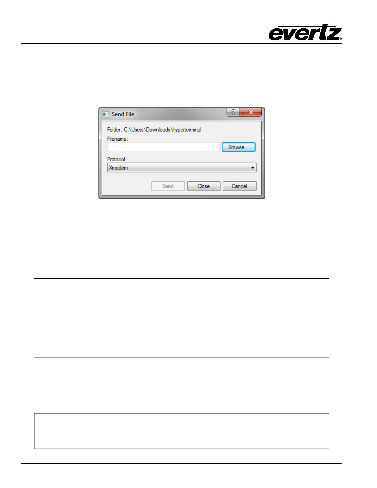
1. At the “Upload Main Program” prompt, send the boot loader program (fcboot_2v0_012.bin) that was
dow nload ed in sec tion 7.3.1 t o the 7800FC using Xm odem protocol. This is done by sel ecting “Send
file…” from the “Transfer” drop-dow n m enu in the HyperTerminal w indow. Upon selec ting this option,
the followi ng screen is di splay ed:
Figure 7-3: Send File Window
Th e “F old er” h eader desc ri bes th e fol der l oc ati on of th e pr eviou sl y dow n load ed Up gr ade P rog ram . To
ch ange the location/name of t he fil e, use the “Brow se…” butt on to locate and selec t the c orrec t file.
Make s ure the Protocol is s et to “ Xm odem” and p ress t he “Send” b utton to s end the file.
Up on c ompl etion t h e c ard wi l l c on t i n u e t o reb oot . A f t er t h e c ard r eb oot s y ou c an s c r ol l to t he t op of the
HyperTerminal buffer and the following information will be displayed:
MON8240 1.1 BUILD 4.
COPYRIGHT 2000 EVERTZ MICROSYSTEMS LTD. ALL RIGHTS RESERVED.
UPGRADE JUMPER PRESENT
UPLOAD MAIN PROGRAM
BB0BB0
UPLOAD OKAY
RUNNING 6C0000
>> NetBSD/evertz 7800FC
7.3.7. Upgrading the 7800FC Frame Controller
1. Pul l t h e card ou t of t h e s l ot an d t h en rei n ser t i t b ac k i n t o t h e fr am e. Af t er the c ar d p ow er s up an d the
“Up l oad Mai n P r og ram” messag e i s di s pl ay ed , pr es s <Ctrl-x> fiv e ( 5) t i mes. T h i s ac tion t emporarily
postpones the “upgrade” procedur e. Th e f ollowing inf ormation is displ ayed on the screen:
Evertz PPCBoot 2.3 et.816
8313e rev. 2.2, e300c3 rev. 1.0, 167 MHz bus, 333 MHz core
link up, 1000 Mbit/s, duplex
user requested abort
Page-26 Revision 1.0
Page 33

7800 MultiFrame Manual
Evertz PPCBoot 2.3 et.816
upload product firmware now
Evertz PPCBoot 2.3 et.816
PPCBOOT>
Evertz PPCBoot 2.3 et.816
CLI>
card is operating in DHCP mode. You will have to turn off DHCP mode and
7800FC VistaLINK® Frame Controller
2. At the prompt “>”, type “upgrade<space>–u<Enter>” The fol lowing is di splay ed on the screen:
8313e rev. 2.2, e300c3 rev. 1.0, 167 MHz bus, 333 MHz core
link up, 1000 Mbit/s, duplex
user requested abort
PPCBOOT> upgrade
3. Using the procedure outlined in section 7.3.6 send the upgrade program that was downloaded in
section 7.3.1 to th e 7800FC. Up on com p l et i on of t hi s step, t h e fol l owin g i n f ormat i on wil l b e di splayed
on the screen:
8313e rev. 2.2, e300c3 rev. 1.0, 167 MHz bus, 333 MHz core
link up, 1000 Mbit/s, duplex
user requested abort
PPCBOOT> upgrade
upload product firmware now
upload okay
4. At the prompt, type “boot<Enter>”. The f ollowing inf ormation is displayed on the screen:
8313e rev. 2.2, e300c3 rev. 1.0, 167 MHz bus, 333 MHz core
link up, 1000 Mbit/s, duplex
user requested abort
PPCBOOT> upgrade
upload product firmware now
upload okay
PPCBOOT> boot
LOADING PROGRAM SECTIONS
LOAD COMPLETE
780XFC hardware test code
RCWHR = 84546c00 RCWLR = 65040000
total memory = 268435456 bytes
available memory = 261668864 bytes
init_main
serial init
[ftpd]ftpd proc has started
Th e IP add res s, net m ask an d g at ew ay i n f ormat i on i s ext racted fr om th e 7800FC con fi g u ration i nf ormat i on
as ent ered in the previ ous section. This IP address shoul d be recorded as it i s used for 7800FC Frame
Controller im age upgrading, as per the next instruc tion.
If the IP address, netmask and gateway are set to 0.0.0.0, this indicates that the
Revision 1.0 Page-27
7800FC
enter a static IP address and netmask using th e p rocedure sh ow n in section 6.2.1.
Page 34

7800 MultiFrame Manual
7800FC VistaLINK® Frame Controller
5. Using the “Run…” c omm and in t he “Start” menu, or opening a Com m and Prompt (MS-DOS) w indow,
type “ftp 192.168.1.187<Enter>” (or similar IP address from the previous instruction, as
displayed). This w ill open an MS-DO S F TP w in dow. Not e that the PC, used for entering comm ands
and storing the dow nloaded image file, and 7800FC must b e c on fi g ur ed t o oper at e on t h e same LA N .
For example the IP address of the PC and Fram e Controller shoul d be on 192.168.1.x with “x” being a
unique address identifier for the P C and the 7800FC F rame Controller
• Do not enter a name for “ User” when prompted (leav e the field blank ). Press <Enter>.
• Do not enter a name for “ Password” when prompted (leave the fiel d blank). Press <Enter>.
6. At the “ftp>” prom pt, type:
put<space>“[dir]\XvY_Z_7800FC.bin”<space>image<Enter>
Ad d t he f ul l p ath nam e (d ir ec tor y loc at ion ) of th e dow nl oaded 7800FC I mage f i l e i n p l ac e of [dir] in
th e above en try . If ther e are spac es i n th e path nam e th ey mu st b e sur round ed by q uot ation s. N ote
th at “ X ”, “Y ” and “Z ” ar e FC i m age r eleas e vers ion num b ers as id ent if ied in th e dow nl oaded fi le nam e.
The fil e will t ake appr oximately 5 to 10 minutes t o upload.
• Upon successful command entry, the MS-DOS window will display “200 PORT command
successful” and “150 Opening data connection” messages.
• Af ter sever al m i nu tes of “i m age” up load , th e MS-DOS w indow w ill display “226 Transfer c omplete”
and “ftp:…(adding statistics about the ftp procedure)”
7. Upon completion of the upload, the MS-DOS window/program should be terminated by closing the
w indow. Rem ove the 7800FC from the f rame, remove t he upg rade cable and reposition the UPGRAD E
jumper to RUN mode. The 7800FC has been upgraded with the latest image and can now be
reinserted i nto t he frame to r esume normal op erati on.
Page-28 Revision 1.0
Page 35
7800 MultiFrame Manual
7800FC VistaLINK® Frame Controller
8. WEBEASY® WEB INTERFACE
The 7800FC provides a built-in w eb interface that allows a user to interac t with th e 7800FC as well as
WebEASY
accessed b y en tering t he IP address of t he 7800FC into the address bar of an Internet web browser. When
first visiting the 7800FC web interface, the user will be asked to enter a Login and Password. Both the
Log in and Pass word have a default value of “customer”.
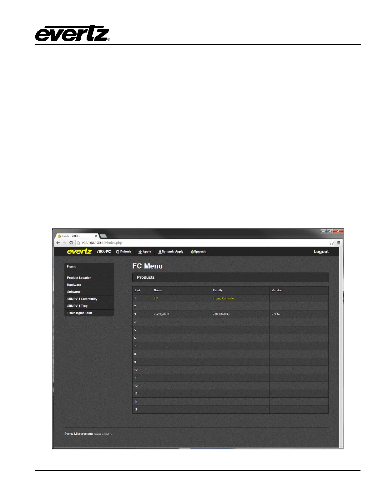
The home page of the 7800FC provides a list of all products currently under the control of the 7800FC
along with a menu that allows insight into specific Product Location, Hardw are version, Software version,
SNMP V1 Community strings, SNMP V1 Trap dest inat ion s and l ocal TRAP Management Fault s for t he
7800FC. The home page of the 7800FC web interface is shown in Figure 8-1.
The FC Menu w ill provide a list of all products currently i n the fram e occupied by the 7800FC. It will also
pr ovid e t he fi rm w are v ersi on of each car d i n t he f ram e. Card s t hat app ear in whi t e text do not sup por t t he
WebEASY
configured using VistaLINK
on the yel low product name will link to th e controls available for that card .
Cards can be c onfigured using t he Refresh, Apply ,and Dy namic Apply buttons on top of t h e p age. Th ese
function in the same m anner as the buttons of t he same nam e in V ist aLINK
supported products usi ng a standard Internet web browser. T he 7800FC web interface can be
®
i nter face and are t herefor e not conf igu rabl e thou gh t he w eb in terf ace. T hese c ards mu st b e
®
. C ards t hat support the WebEAS Y® interface will appear in yellow. Clicking
®
.
®
Figure 8-1: WebEASY
Revision 1.0 Page-29
Home Page
®
Page 36
7800 MultiFrame Manual
7800FC VistaLINK® Frame Controller
8.1. UPGRADING CARDS USING WEBEASY®
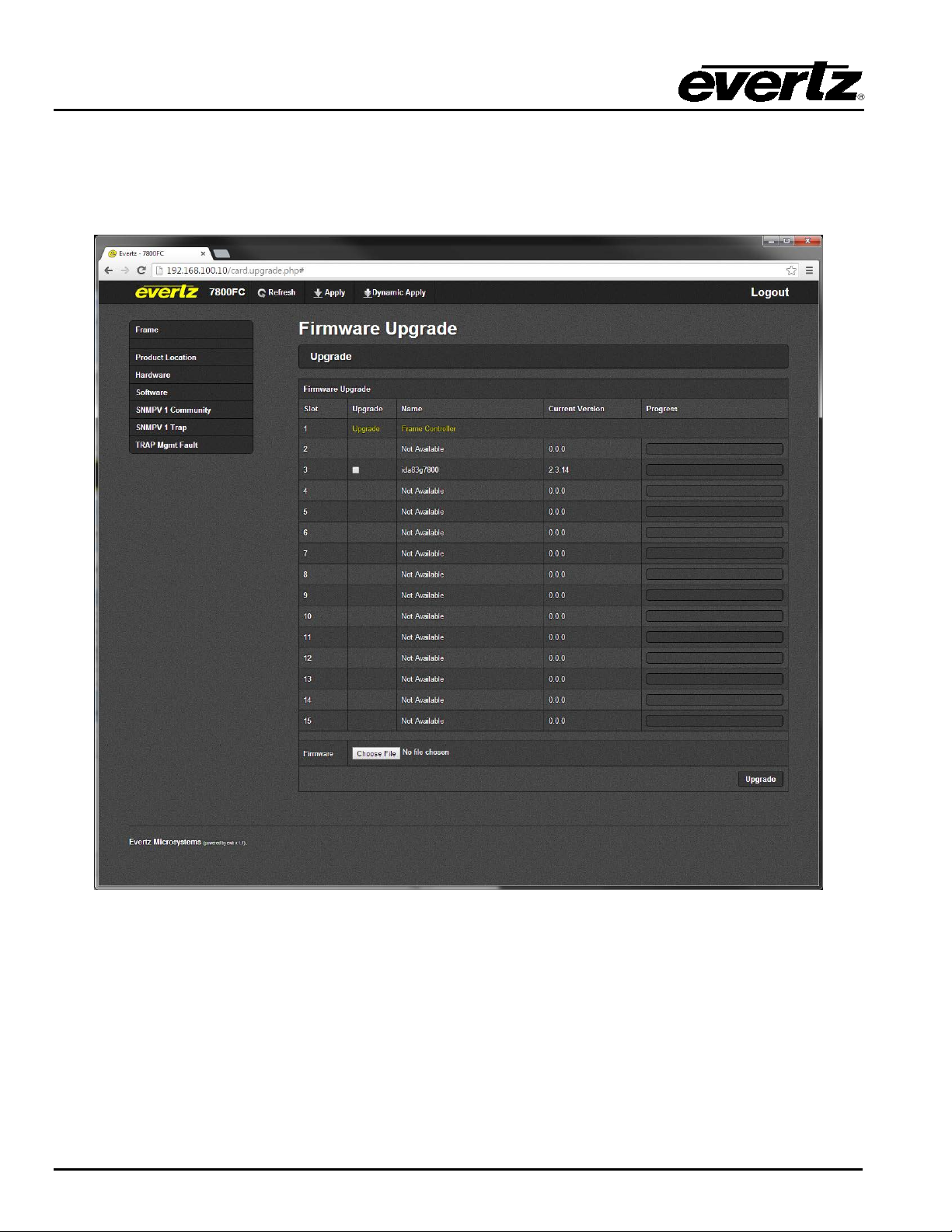
Th e 78 0 0F C w eb i n t er face p rov i des a si mpl e way t o u pg r ade b ot h t h e fi r mwar e on t he 7800FC as well as
th e firmw are of c ards that suppor t W ebEASY
screen will bring the user to the Firm ware Upgrade page as shown in Figure 8-2.
. Clicking on the Upgrade button at t he top of the home
®
Figure 8-2: WebEASY
8.1.1. Upgrading Modules Using WebEASY
Firmware Upgrade Page
®
®
The firmw are for individual m odules in a frame with a 7800FC can be upgraded using the web interfac e.
Bes id e eac h com p ati bl e p rod uc t w i ll be a c h eck box. Sel ec t the checkbox of the card to be upgraded and
then clic k on the t he Choos e F il e bu tt on t o sel ec t t h e desi red fir m w are fr om a loc al dri ve. Clicking on t h e
Upgrade button will star t the process. The progress bar t o the right of t he card slot will provi de feedb ack on
the status of the upgrade.
Page-30 Revision 1.0
Page 37
7800 MultiFrame Manual
7800FC VistaLINK® Frame Controller
8.1.2. Upgrading 7800FC Using WebEASY®
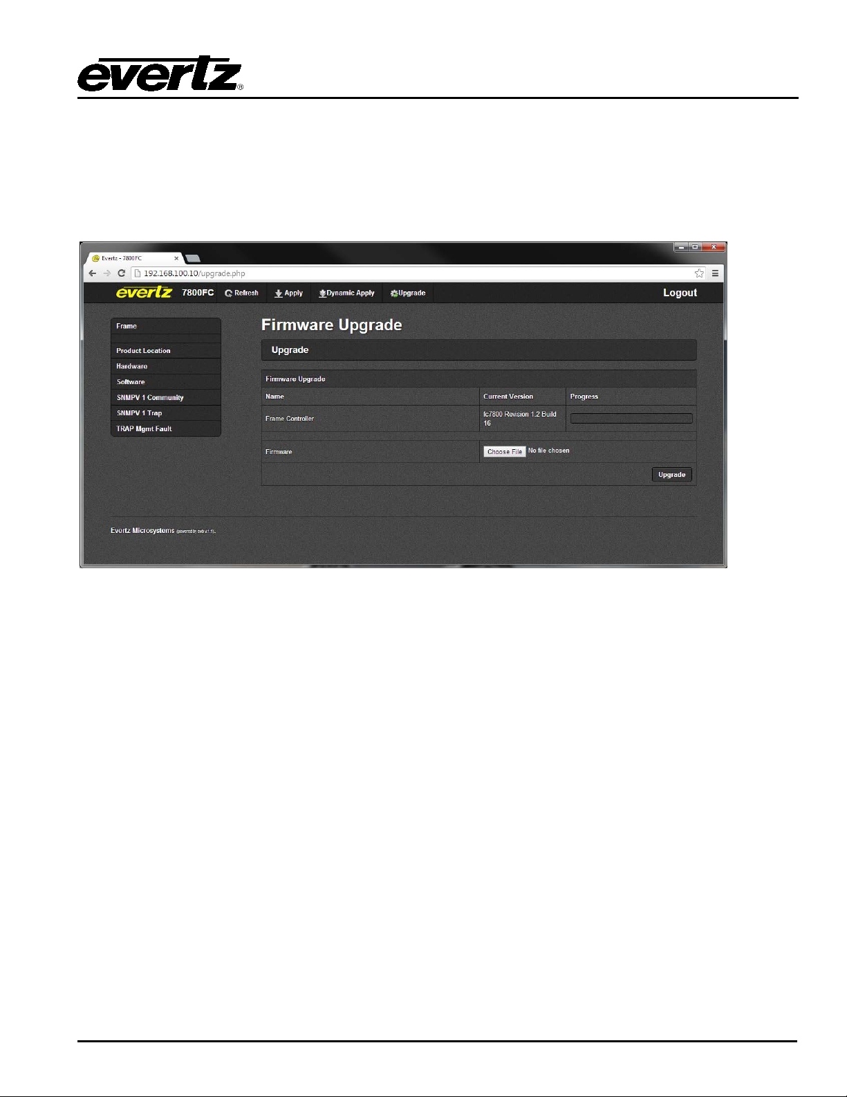
The firmw are for the 7800FC can be upgraded by clicking on the Upgrade l i n k b esi d e t h e fr ame c ont r ol l er
in slot 1. Clic king on t he link wil l bring the user to the 7800F C Fi rmware Upgrade page shown in Figure
8-3. Once on this page, click on the Ch oose Fi le but t on t o sel ect t he des ir ed fi rm w ar e from a l oc al d riv e,
then click on the Upgrade butt on to st art t he proc ess. The pr ogress bar t o th e righ t of t he card slot will
pr ovide feedbac k on the status of the upgrad e.
Figure 8-3: WebEASY
Firmware Upgrade Page for 7800FC
®
Revision 1.0 Page-31
Page 38

7800 MultiFrame Manual
7800FC VistaLINK® Frame Controller
This page left intentionally bl ank
Page-32 Revision 1.0
 Loading...