

Page 1

7700 MultiFrame Manual
7700TPI VistaLINK Third Party Interface Module
TABLE OF CONTENTS
1. OVERVIEW...............................................................................................................................1
2. INSTALLATION........................................................................................................................2
2.1. CONNECTING GPI/GPO, RS-232/422 INTERFACES.................................................................. 3
2.2. GENERAL PURPOSE INPUTS & OUTPUTS................................................................................ 6
2.3. CONFIGURING THE MODULE OVER AN RS-232 SERIAL CONNECTION................................ 7
2.3.1. Network Configuration Menu............................................................................................ 9
2.3.2. SNMP Configuration Menu............................................................................................. 10
2.3.3. Auxiliary Serial Port Configuration Menu........................................................................ 11
3. SPECIFICATIONS..................................................................................................................12
3.1. GENERAL PURPOSE INTERFACE INPUTS.............................................................................. 12
3.2. GENERAL PURPOSE INTERFACE OUTPUTS.......................................................................... 12
3.3. DATA INPUT SERIAL PORT....................................................................................................... 12
3.4. ELECTRICAL.............................................................................................................................. 12
3.5. PHYSICAL................................................................................................................................... 12
4. STATUS INDICATORS...........................................................................................................13
5. CARD EDGE CONTROLS......................................................................................................14
6. LOCATION OF LEDS AND JUMPERS..................................................................................15
6.1. SELECTING WHETHER LOCAL FAULTS WILL BE MONITORED
THE GLOBAL FRAME STATUS........................................................................................... 15
BY
6.2. CONFIGURING THE MODULE FOR FIRMWARE UPGRADES................................................. 15
6.2.1. Upgrading the Firmware Using FTP............................................................................... 16
6.2.1.1. Determine the IP Address of the Module........................................................... 16
6.2.1.2. Establishing a Valid Network Connection.......................................................... 16
6.2.1.3. FTP Upgrade ..................................................................................................... 17
6.2.1.4. Completing the FTP Upgrade............................................................................ 19
6.2.2. Upgrading the Firmware Over an RS-232 Serial Connection......................................... 19
6.3. CONTROLLING GPI PULLUP VOLTAGE .................................................................................. 19
7. VISTALINK® REMOTE MONITORING/CONTROL ................................................................20
7.1. W
7.2. V
7.3. V
7.4. V
Revision 0.2
HAT IS VISTA
ISTA
LINK
®
ISTA
LINK
®
ISTA
LINK
®
LINK®? .................................................................................................................. 20
MONITORED PARAMETERS................................................................................. 20
CONTROLLED PARAMETERS.............................................................................. 20
TRAPS..................................................................................................................... 21
Page 2

7700 MultiFrame Manual
7700TPI VistaLINK Third Party Interface Module
Figures
Figure 1-1: 7700TPI Block Diagram.........................................................................................................................2
Figure 2-1: 7700TPI Rear I/O Module and Pinout Assignments..............................................................................3
Figure 2-2: Typical GPI Circuitry ..............................................................................................................................7
Figure 2-3: Typical GPO Circuitry ............................................................................................................................7
Figure 2-4: 7700TPI Main Menu...............................................................................................................................8
Figure 2-5: 7700TPI Network Configuration Menu...................................................................................................9
Figure 2-6: 7700TPI SNMP Configuration Menu ...................................................................................................10
Figure 2-7: 7700TPI Auxiliary Serial Port Configuration Menu ..............................................................................11
Figure 4-1: LED Status Indicators and Card Edge Controls ..................................................................................13
Figure 5-1: Card Edge Controls .............................................................................................................................14
Figure 6-1: LED and Jumper Locations..................................................................................................................15
Figure 6-2: Opening a DOS Command Window....................................................................................................16
Figure 6-3: Pinging a 7700TPI Module...................................................................................................................17
Figure 6-4: FTP Upgrading a 7700TPI Module......................................................................................................18
Tables
Table 2-1: Upper Left 2x6 Terminal Block Connector Pin Assignments..................................................................4
Table 2-2: Lower Left 2x17 Terminal Block Connector Pin Assignments................................................................5
Table 2-3: Lower Right 2x17 Terminal Block Connector Pin Assignments .............................................................6
Table 2-4: 7700TPI Configuration COM Settings.....................................................................................................8
Table 7-1: VistaLINK® Monitored Parameters........................................................................................................20
Table 7-2: VistaLINK® Controlled Parameters .......................................................................................................20
Table 7-3: VistaLINK® Traps ..................................................................................................................................21
Revision 0.2
Page 3

7700 MultiFrame Manual
7700TPI VistaLINK Third Party Interface Module
REVISION HISTORY
REVISION DESCRIPTION DATE
0.1 Preliminary version Aug 06
0.2 Updated VistaLINK
Information contained in this manual is believed to be accurate and reliable. However, Evertz assumes no responsibility for the use thereof nor for
the rights of third parties, which may be affected in any way by the use thereof. Any representations in this document concerning performance of
Evertz products are for informational use only and are not warranties of future performance, either expressed or implied. The only warranty offered
by Evertz in relation to this product is the Evertz standard limited warranty, stated in the sales contract or order confirmation form.
Although every attempt has been made to accurately describe the features, installation and operation of this product in this manual, no warranty is
granted nor liability assumed in relation to any errors or omissions unless specifically undertaken in the Evertz sales contract or order confirmation.
Information contained in this manual is periodically updated and changes will be incorporated into subsequent editions. If you encounter an error,
please notify Evertz Customer Service department. Evertz reserves the right, without notice or liability, to make changes in equipment design or
specifications.
section. General cleanup. Dec 08
®
Revision 0.2
Page 4

7700 MultiFrame Manual
7700TPI VistaLINK Third Party Interface Module
This page left intentionally blank
Revision 0.2
Page 5

7700 MultiFrame Manual
7700TPI VistaLINK Third Party Interface Module
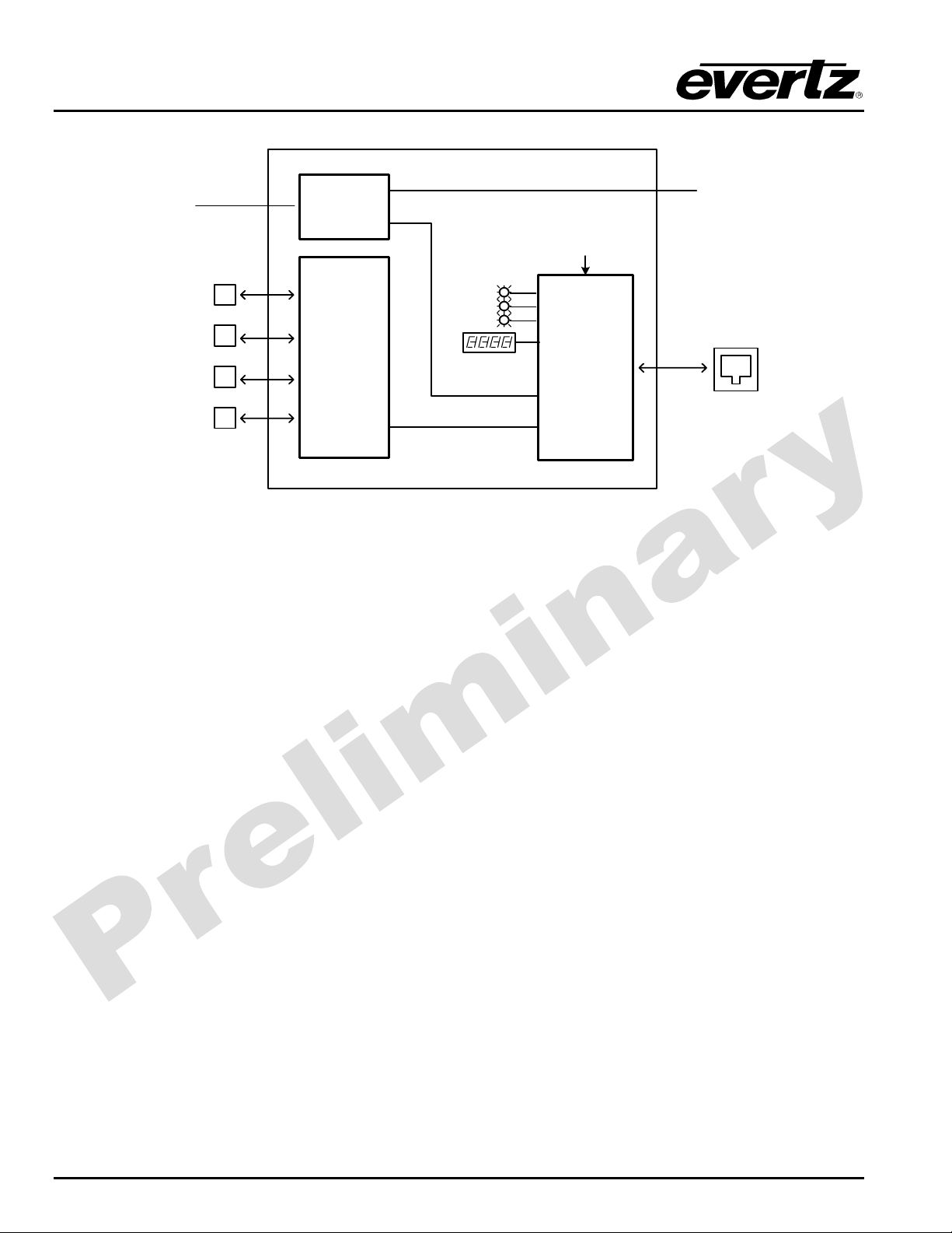
1. OVERVIEW
The 7700TPI VistaLINK® module links third-party equipment and Evertz VistaLINK® Network Management
System (NMS). Third-party equipment with fault alarming capabilities via General Purpose Interface
outputs (GPO), serial RS-232/422/485 connection, or Ethernet can communicate fault alarm conditions to
the VistaLINK
monitoring capabilities across the broadcast network.
The 7700TPI comes equipped with 4 RS-232/422/485 serial ports and 1 10/100 Mb Ethernet port. These
ports can also be utilized to communicate and provide remote control to third-party equipment.
The 7700TPI module is also equipped with 8 General Purpose Interface outputs (GPO) and can be utilized
to relay a state level from the VistaLINK
fault alarming are also possible through this interface.
The 7700TPI module fits conveniently into Evertz’s universally installed 7700FR-C frame and provides a
cost-effective and space-efficient third-party interface (TPI) solution.
VistaLINK
Management Protocol (SNMP) giving the flexibility to manage operations, including signal monitoring and
module configuration from SNMP capable control systems (Manager or NMS).
Features:
• 20 opto-isolated General Purpose Interface inputs (GPI)
• Enabled GPI alerts translated and reported to Network Management System (NMS) user interface via
SNMP
• Selectable +5V or +12V supply for driving GPI over longer cable runs
• 8 relay closure General Purpose Interface outputs (GPO)
• 4 serial ports RS-232/422 selectable
• GPI/GPO/Serial connections easily accessed through pin-headers (Phoenix Terminal Blocks) on rear
plate
• Modular, conveniently fits into 7700FR-C 3RU frame
• Module status LED and simple GPI input diagnostics
• Frame status trigger
• VistaLINK
application software through the 7700TPI to SNMP translator thereby extending fault
®
system to connected gear. Configuration changes or additional
®
offers remote monitoring, control and configuration capabilities via Simple Network
®
enabled for remote monitoring and control via SNMP
®
Revision 0.2
7700TPI-1
Page 6
7700 MultiFrame Manual
7700TPI VistaLINK Third Party Interface Module
20 GPIs
Serial Port #1
(RS-232/422)
GPI/O
GPI Status
Card Edge
Control
8 GPOs
Serial Port #2
(RS-232/422)
Serial Port #3
(RS-232/422)
Serial Port #4
(RS-232/422)
Serial I/O
Alphanumeric Card Edge
Status Display
CPU
Ethernet
VistaLINK®
Interface
Figure 1-1: 7700TPI Block Diagram
2. INSTALLATION
The 7700TPI comes with a companion rear plate that occupies 2 slots in the frame. For information on
inserting the module into the frame see the 7700FR chapter section 3.
7700TPI-2
Revision 0.2
Page 7
7700 MultiFrame Manual
7700TPI VistaLINK Third Party Interface Module
GPI 01
12
GPI 03
34
GPI 05
56
GPI 07
78
GPI 09
910
GND
11 12
GPI 11
12
GPI 13
34
GPI 15
56
GPI 17
78
GPI 19
910
GND GND
11 12
13 14
GPO1:NC
15 16
GPO1:NO
17 18
GENERAL PURPOSE IN / OUT
GPO3:NC
19 20
GPI 02
GPI 04
GPI 06
GPI 08
GPI 10
GND
GPI 12
GPI 14
GPI 16
GPI 18
GPI 20
GNDGPO:COM
GPO2:NC
GPO2:NO
GPO4:NC
11 12
13 14
15 16
17 18
RS-232/422 DATA
19 20
TX A
12
TX+ A RX+ A
34
GND
56
78
TX B RX B
910
TX+ B RX+ B
GND GND
TX C RX C
TX+ C RX+ C
---
---
RX A
GND
---
---
21 22
GPO3:NO
GND
23 24
25 26
GPO5:NC
27 28
GPO5:NO
GPO7:NC
29 30
GPO7:NO
31 32
33 34
GND GND
GPO4:NO
GND
GPO6:NC
GPO6:NO
GPO8:NC
GPO8:NO
21 22
GND GND
TX D
23 24
25 26
GND GND
27 28
29 30
31 32
33 34
--- ---
--- ---
GND GND
--- ---
RX D
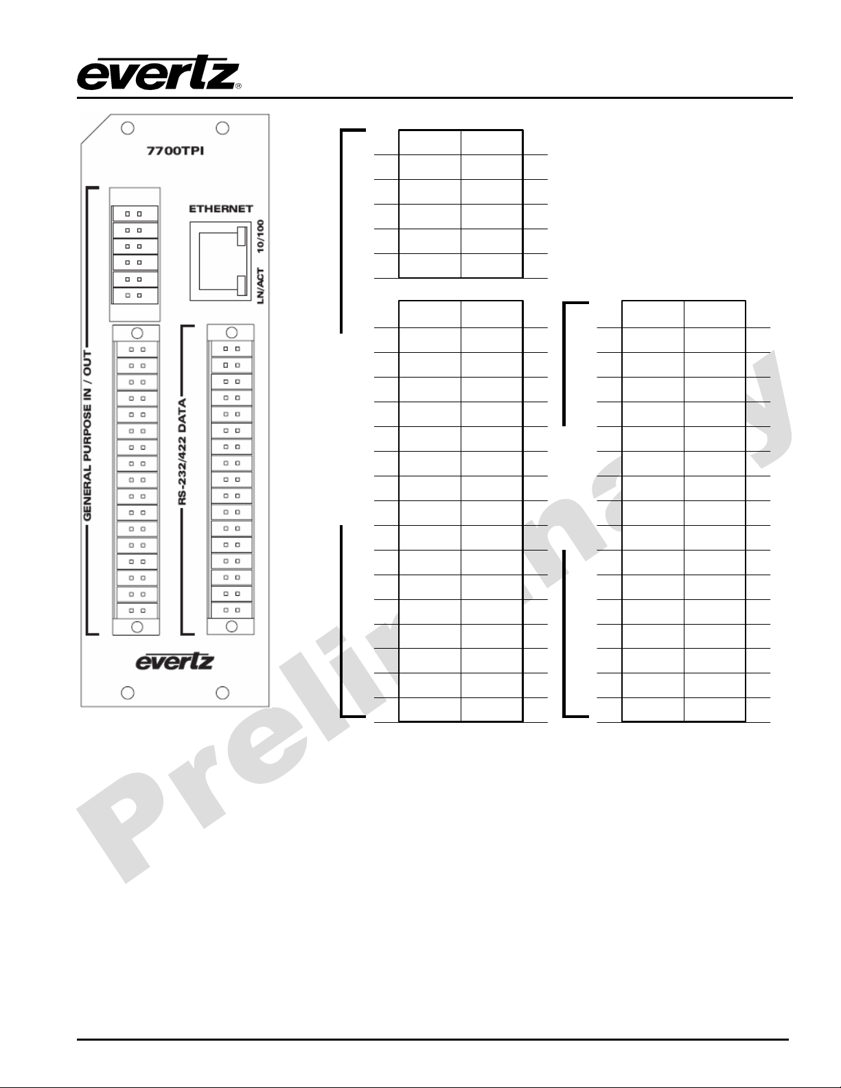
Figure 2-1: 7700TPI Rear I/O Module and Pinout Assignments
2.1. CONNECTING GPI/GPO, RS-232/422 INTERFACES
Three Terminal Block connectors are used to interconnect GPI, GPO, and serial communication lines to
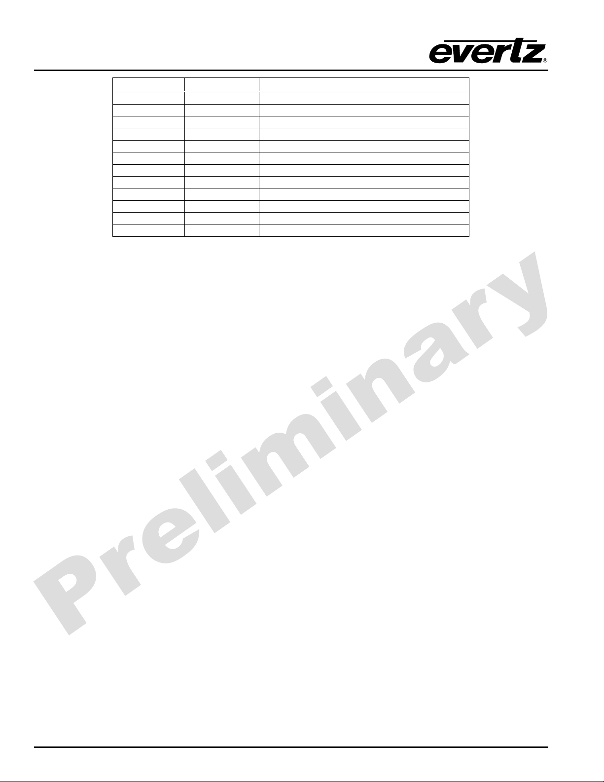
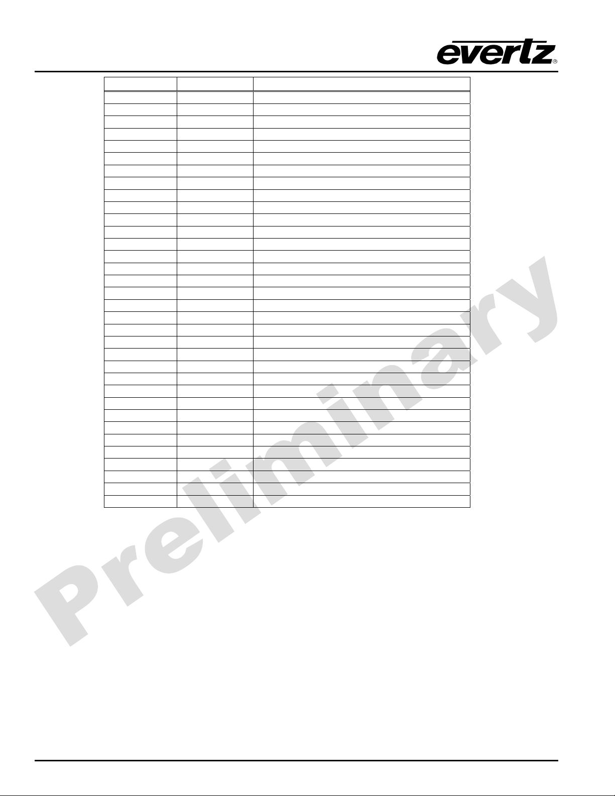
the 7700TPI module. The pins are identified in Figure 2-1 and defined in Table 2-1, Table 2-2 and Table
2-3. The input cables can be secured into the removable portion of the terminal strips using a small
screwdriver. The removable part of the terminal strip is then inserted into the rear panel and can be
secured using the hold down screws.
Revision 0.2
7700TPI-3
Page 8
7700 MultiFrame Manual
7700TPI VistaLINK Third Party Interface Module
Pin Number Pin Name Pin Description
1
2
3
4
5
6
7
8
9
10
11
12
GPI 1 General Purpose Input 1
GPI 2 General Purpose Input 2
GPI 3 General Purpose Input 3
GPI 4 General Purpose Input 4
GPI 5 General Purpose Input 5
GPI 6 General Purpose Input 6
GPI 7 General Purpose Input 7
GPI 8 General Purpose Input 8
GPI 9 General Purpose Input 9
GPI 10 General Purpose Input 10
GPI 11 General Purpose Input 11
GPI 12 General Purpose Input 12
Table 2-1: Upper Left 2x6 Terminal Block
Connector Pin Assignments
7700TPI-4
Revision 0.2
Page 9

7700TPI VistaLINK Third Party Interface Module
Pin Number Pin Name Pin Description
1
2
3
4
5
6
7
8
9
10
11
12
13
14
15
16
17
18
19
20
21
22
23
24
25
26
27
28
29
30
31
32
33
34
GPI 11 General Purpose Input 11
GPI 12 General Purpose Input 12
GPI 13 General Purpose Input 13
GPI 14 General Purpose Input 14
GPI 15 General Purpose Input 15
GPI 16 General Purpose Input 16
GPI 17 General Purpose Input 17
GPI 18 General Purpose Input 18
GPI 19 General Purpose Input 19
GPI 20 General Purpose Input 20
GND Ground
GND Ground
GPO:COM General Purpose Output Common
GND Ground
GPO1:NC General Purpose Output 1 – Normally Closed
GPO2:NC General Purpose Output 2 – Normally Closed
GPO1:NO General Purpose Output 1 – Normally Open
GPO2:NO General Purpose Output 2 – Normally Open
GPO3:NC General Purpose Output 3 – Normally Closed
GPO4:NC General Purpose Output 4 – Normally Closed
GPO3:NO General Purpose Output 3 – Normally Open
GPO4:NO General Purpose Output 4 – Normally Open
GND Ground
GND Ground
GPO5:NC General Purpose Output 5 – Normally Closed
GPO6:NC General Purpose Output 6 – Normally Closed
GPO5:NO General Purpose Output 5 – Normally Open
GPO6:NO General Purpose Output 6 – Normally Open
GPO7:NC General Purpose Output 7 – Normally Closed
GPO8:NC General Purpose Output 8 – Normally Closed
GPO7:NO General Purpose Output 7 – Normally Open
GPO8:NO General Purpose Output 8 – Normally Open
GND Ground
GND Ground
7700 MultiFrame Manual
Table 2-2: Lower Left 2x17 Terminal Block
Connector Pin Assignments
Revision 0.2
7700TPI-5
Page 10
7700 MultiFrame Manual
7700TPI VistaLINK Third Party Interface Module
Pin Number Pin Name Pin Description
1
2
3
4
5
6
7
8
9
10
11
12
13
14
15
16
17
18
19
20
21
22
23
24
25
26
27
28
29
30
31
32
33
34
TX A Serial Port A Transmit
RX A Serial Port A Receive
TX+ A Serial Port A Transmit (RS-422)
RX+ A Serial Port A Receive (RS-422)
GND Ground
GND Ground
TX B Serial Port B Transmit
RX B Serial Port B Receive
TX+ B Serial Port B Transmit (RS-422)
RX+ B Serial Port B Receive (RS-422)
GND Ground
GND Ground
TX C Serial Port C Transmit
RX C Serial Port C Receiv e
TX+ C Serial Port C Transmit (RS-422)
RX+ C Serial Port C Receive (RS-422)
--- No Connect
--- No Connect
--- No Connect
--- No Connect
GND Ground
GND Ground
TX D Serial Port D Transmit
RX D Serial Port D Receiv e
GND Ground
GND Ground
--- No Connect
--- No Connect
--- No Connect
--- No Connect
GND Ground
GND Ground
--- No Connect
--- No Connect
Table 2-3: Lower Right 2x17 Terminal Block
Connector Pin Assignments
2.2. GENERAL PURPOSE INPUTS & OUTPUTS
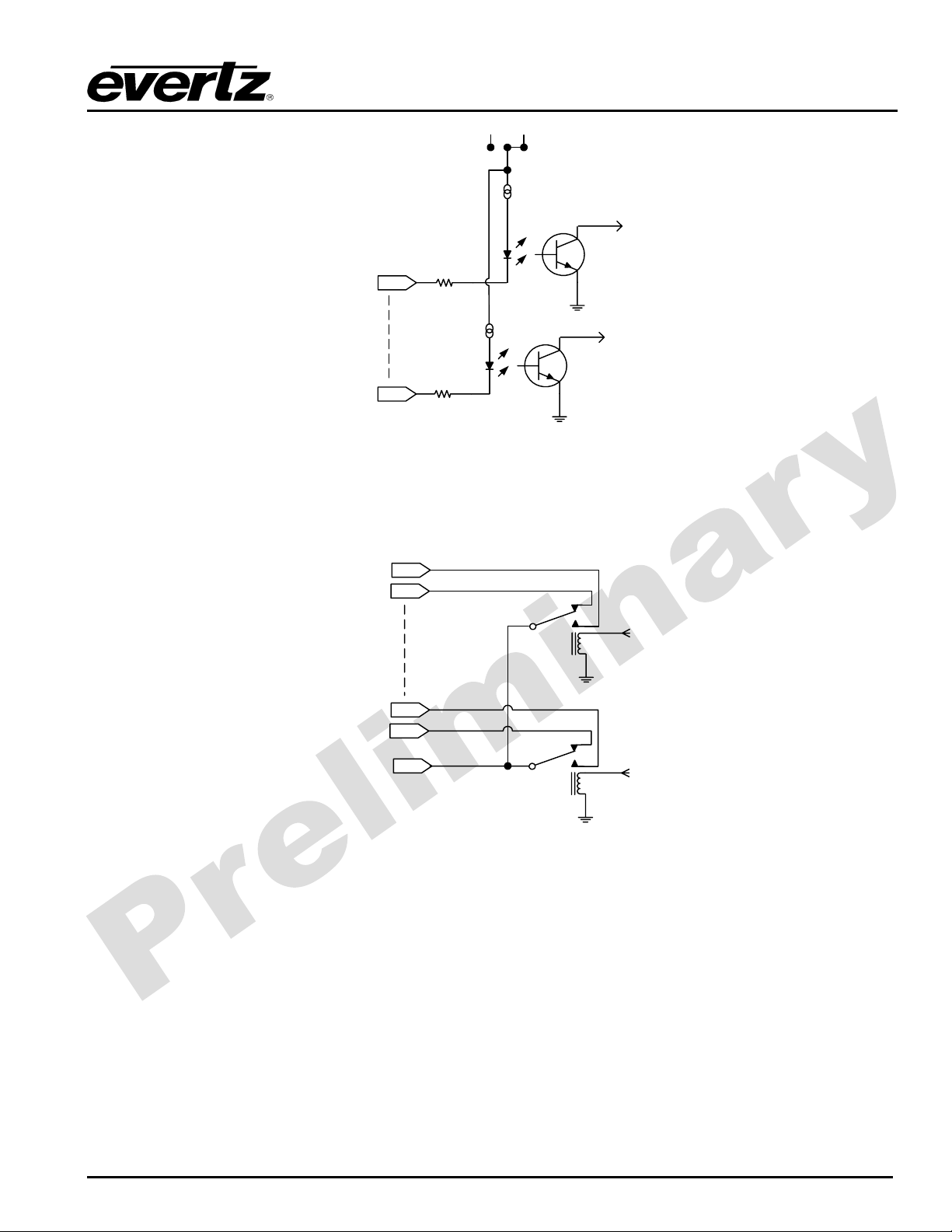
The GPI inputs are active low with internal pull-ups. If an input is left floating (not connected) it will not be
activated. Lowering the GPI input to a voltage below 0.8 volts will activate the input. GPIs can be
activated by simply connecting the GPI input pins to ground using a button, switch, relay, or an open
collector transistor. The inputs are internally pulled up to either +5 or +12 volts DC set by jumper J10
(please refer to Figure 6-1).
7700TPI-6
Revision 0.2
Page 11
7700 MultiFrame Manual
7700TPI VistaLINK Third Party Interface Module
+5V
+12V
GPI PULLUP
20mA
SELECT
to
internal
circuit
GPI 1
GPI x
10
20mA
10
to
internal
circuit
Figure 2-2: Typical GPI Circuitry
The GPO outputs are normally closed and normally open dry relay contacts and share a common
connection which can be tied to the module ground or to another reference voltage.
GPO1 NO
GPO1 NC
from
internal
circuit
GPOx NO
GPOx NC
GPO Common
from
internal
circuit
Figure 2-3: Typical GPO Circuitry
2.3. CONFIGURING THE MODULE OVER AN RS-232 SERIAL CONNECTION
Through the card-edge’s serial port, and using the serial 7700 upgrade cable connected to a PC’s serial
port running HyperTerminal (or equivalent), the 7700tpi module’s IP address, subnet, and SNMP TRAP
destination address are identified. The 7700 upgrade cable supplied with the 7700FR-C frame is a multicolored ribbon cable with a six pin header socket on one end and a female 9 pin D connector on the other
end, (Evertz part number
WA-S76)
is normally in the vinyl pouch at the front of the manual binder.
Configure the port settings of the terminal program as follows:
Revision 0.2
7700TPI-7
Page 12
7700 MultiFrame Manual
7700TPI VistaLINK Third Party Interface Module
Baud
Data bits
Parity
Stop bits
Flow Control
Table 2-4: 7700TPI Configuration COM Settings
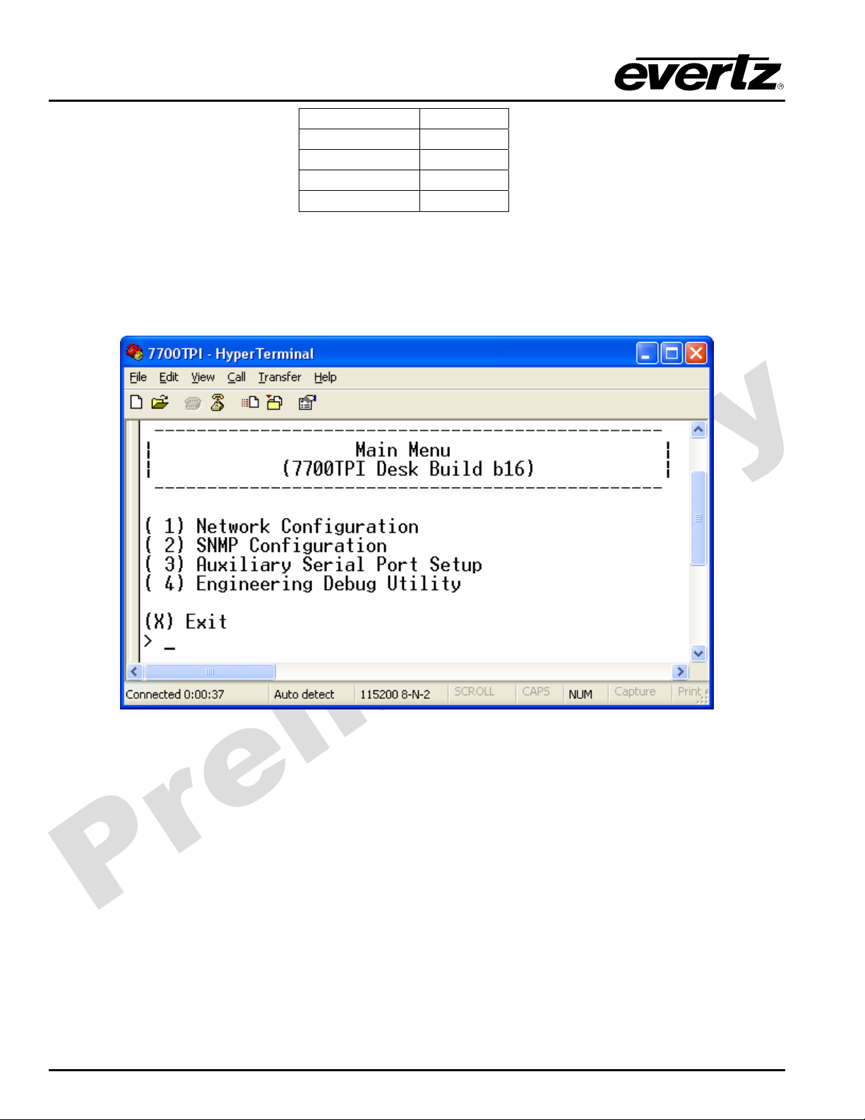
Press the <Enter> key to see the main Menu. In the Main Menu, the following options are present for
module configuration. Once changes completed and saved, the 7700tpi module should be power-cycled
for the changes to take effect.
115200
8
None
2
None
7700TPI-8
Figure 2-4: 7700TPI Main Menu
Revision 0.2
Page 13
7700 MultiFrame Manual
7700TPI VistaLINK Third Party Interface Module
2.3.1. Network Configuration Menu
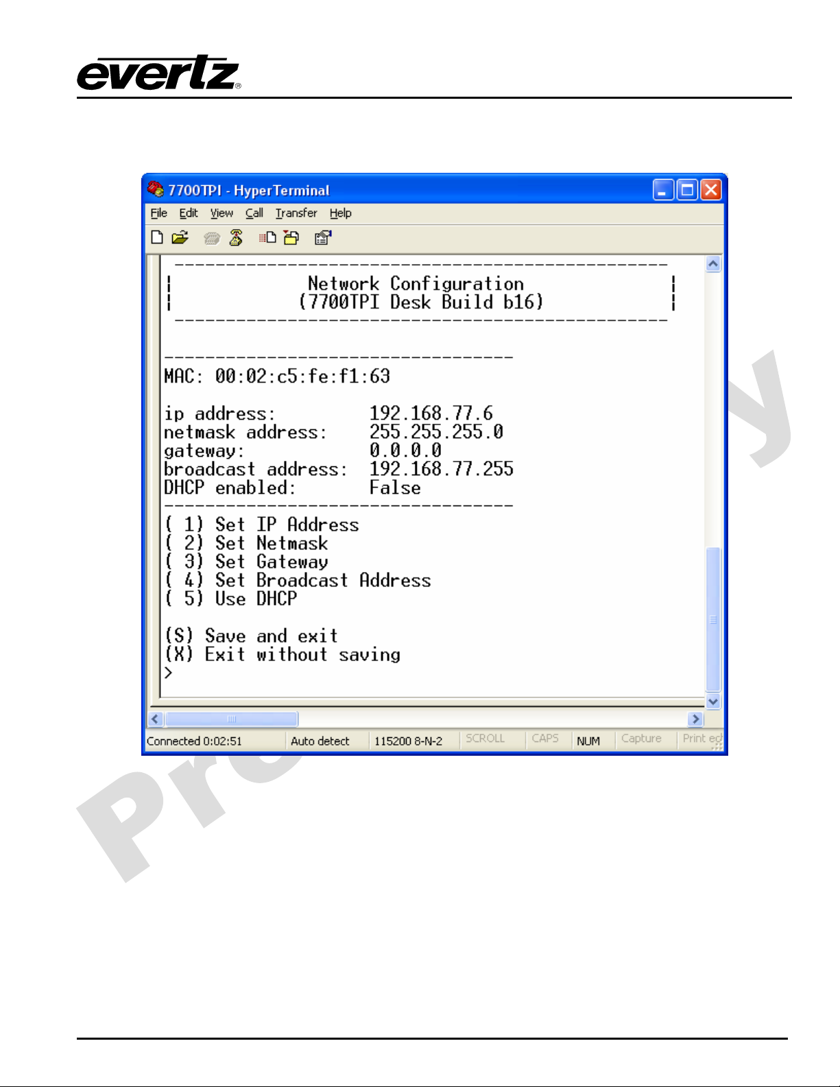
This menu option is used to configure the network IP settings of the module. Refer to Figure 2-5
Figure 2-5: 7700TPI Network Configuration Menu
Revision 0.2
7700TPI-9
Page 14
7700 MultiFrame Manual
7700TPI VistaLINK Third Party Interface Module
2.3.2. SNMP Configuration Menu
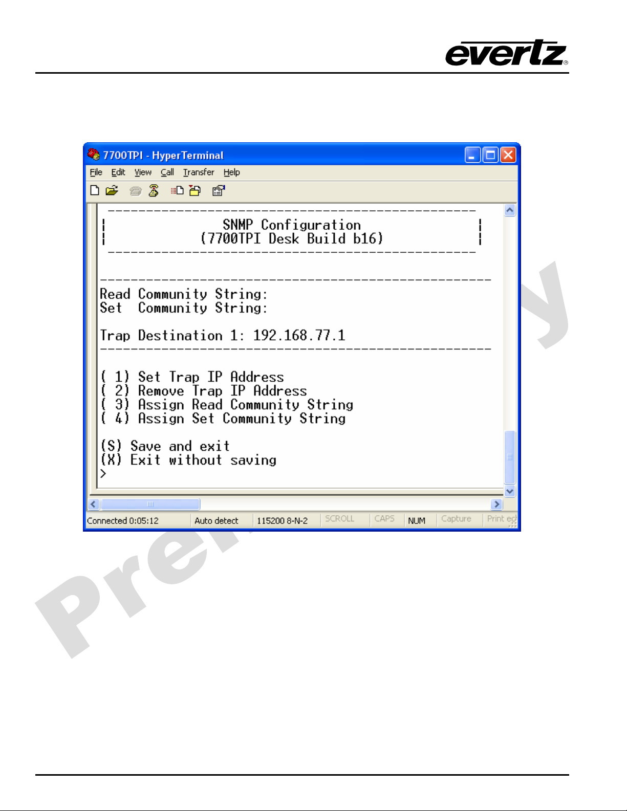
This menu option is used to configure the SNMP settings of the module. A maximum of 5 SNMP trap
destinations can be configured. Refer to Figure 2-6.
7700TPI-10
Figure 2-6: 7700TPI SNMP Configuration Menu
Revision 0.2
Page 15
7700 MultiFrame Manual
7700TPI VistaLINK Third Party Interface Module
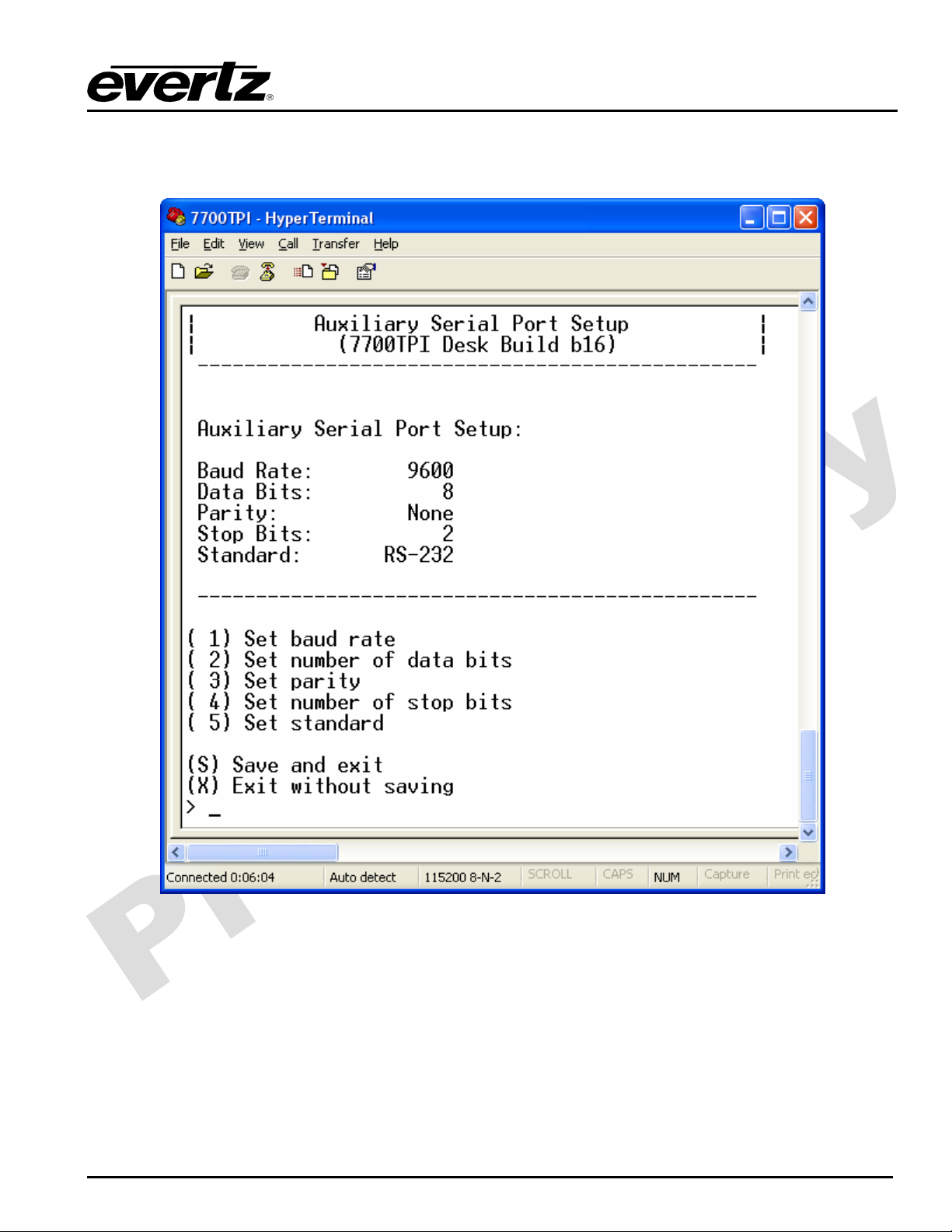
2.3.3. Auxiliary Serial Port Configuration Menu
This menu option is used to configure the serial port settings of the module. Refer to Figure 2-7.
Figure 2-7: 7700TPI Auxiliary Serial Port Configuration Menu
Revision 0.2
7700TPI-11
Page 16

7700 MultiFrame Manual
7700TPI VistaLINK Third Party Interface Module
3. SPECIFICATIONS
3.1. GENERAL PURPOSE INTERFACE INPUTS
Number of Inputs 20
Type Opto-isolated, active low with jumper selectable +5V or +12V supplied voltage
Connector Terminal Block
Signal Level Jumper selectable +5V or +12V
3.2. GENERAL PURPOSE INTERFACE OUTPUTS
Number of Outputs 8
Type “Dry Contact” relay closure
Connector 2 pins per output on Terminal Block
Signal Level Normally Closed and Normally Open
3.3. DATA INPUT SERIAL PORT
Number of Ports 4 RS-232 or 3 RS-422
Connector Terminal Block
Baud Rate User selectable, up to 115200 bps
3.4. ELECTRICAL
Voltage +12VDC
Power < 6W
Safety: ETL Listed, complies with EU safety directives
EMI/RFI Complies with FCC Part 15, Class A EU EMC Directive
3.5. PHYSICAL
7700 frame mounting:
Number of slots: 2
7701 frame mounting:
Number of slots: 1
Stand Alone Enclosure:
Dimensions: 14” L x 4.5” W x 1.9” H
(355 mm L x 114 mm W x 48 mm H)
Weight: approx. 1.5 lbs. (0.7 Kg)
7700TPI-12
Revision 0.2
Page 17
7700 MultiFrame Manual
7700TPI VistaLINK Third Party Interface Module
4. STATUS INDICATORS
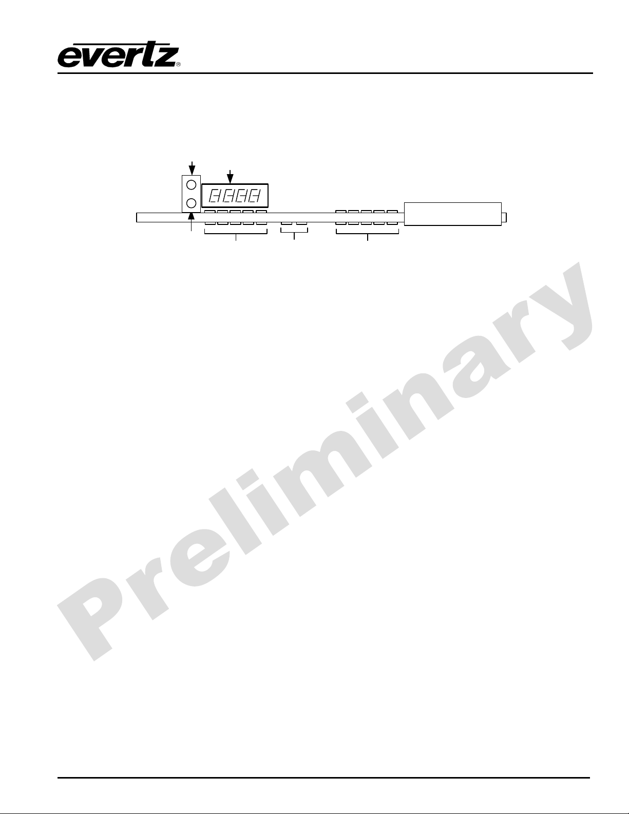
The 7700TPI modules have a number of LED Status indicators on the card edge of the board to show
operational status of the card at a glance. Refer to Figure 4-1.
MODULE
LOCAL
FAULT
Figure 4-1: LED Status Indicators and Card Edge Controls
Two large LEDs on the front of the board indicate the general health of the module.
LOCAL FAULT: This red LED indicates poor module health and will be ON during the absence of a
valid input signal or if a local input power fault exists (i.e.: a blown fuse). The LOCAL
FAULT indication can also be reported to the frame through the FRAME STATUS
jumper.
MODULE OK: This green LED indicates good module health. It will be ON when a valid input
signal is present on both inputs, and the board power is good.
DOT MATRIX: This display will provide high level system information, such as product ID, firmware
version and IP address. This information will be scrolling across the display.
GPI STATUS: These green LEDs indicate when a GPI has been asserted. There are 20 LEDs,
each mapping to a unique GPI.
ETHERNET: These 2 green LEDs indicate when Ethernet activity is detected.
OK
Dot Matrix
Display
7700TPI
GPI StatusGPI Stat us E t hernet
Revision 0.2
7700TPI-13
Page 18
7700 MultiFrame Manual
7700TPI VistaLINK Third Party Interface Module
5. CARD EDGE CONTROLS
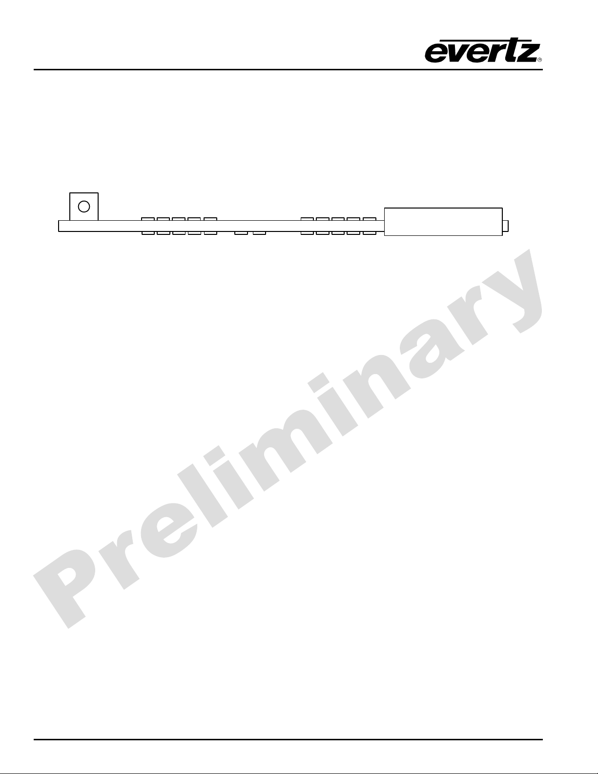
The 7700TPI modules are equipped with a toggle switch. This control can be found towards the top of the
module when inserted within a 7700FR-C frame. Refer to Figure 5-1.
toggle
switch
7700TPI
Figure 5-1: Card Edge Controls
TOGGLE SWITCH: This control is used to factory reset the module during the boot sequence.
7700TPI-14
Revision 0.2
Page 19
7700 MultiFrame Manual
7700TPI VistaLINK Third Party Interface Module
6. LOCATION OF LEDS AND JUMPERS
MODULE STATUS
DOT MATRIX
DISPLAY
GPI STATUS
RUN
J2
UPGRD
J1
UPGRADE
J4
OFF
ON
FRAME STATUS
SFF POWER
6.1. SELECTING WHETHER LOCAL FAULTS WILL BE MONITORED
BY THE GLOBAL FRAME STATUS
J5
+12V
GND
(A)7700PTX
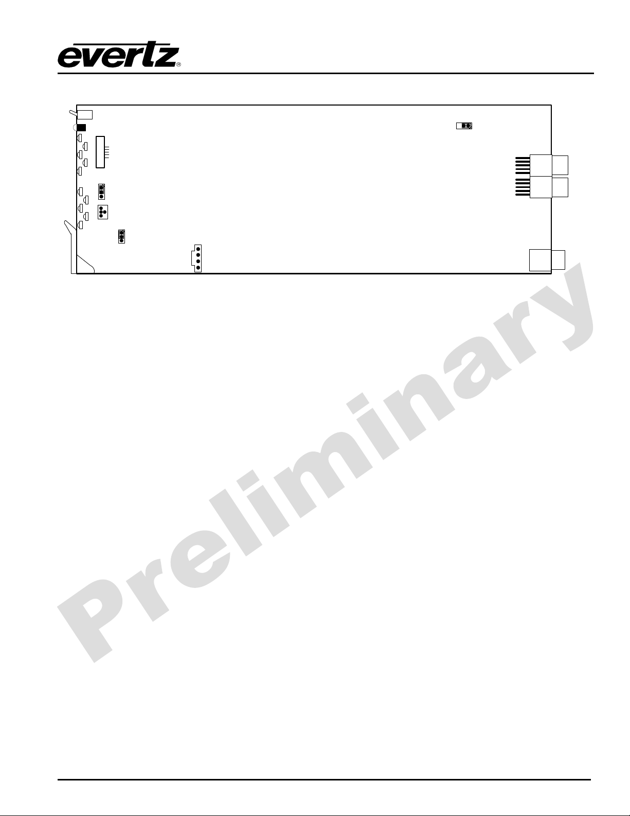
Figure 6-1: LED and Jumper Locations
+5V +12V
GPI Supply Voltage
J10
FRAME STATUS: The FRAME STATUS jumper located at the front of the module determines whether
local faults (as shown by the Local Fault indicator) will be connected to the 7700FRC frame's global status bus.
To monitor faults on this module with the frame status indicators (on the PS FRAME
STATUS LED's and on the Frame's Fault Tally output) install this jumper in the On
position. (Default)
When this jumper is installed in the Off position, local faults on this module will not
be monitored.
6.2. CONFIGURING THE MODULE FOR FIRMWARE UPGRADES
The 7700TPI module contains firmware that is contained in a FLASH EPROM device. From time to time
firmware updates will be provided to add additional features to the unit.
There are two methods of updating the firmware in the 7700TPI: File Transfer Protocol (FTP) and Serial
Upload. To minimize upgrade wait time, the FTP method is the preferred method of updating the
firmware.
Prior to initiating the upgrade process:
• Confirm the version of code currently installed on the unit by using the front panel display.
• Download the new application code from the Evertz FTP site (www.evertz.com) Unzip the file into
a temporary working folder on your PC.
Revision 0.2
7700TPI-15
Page 20
7700 MultiFrame Manual
7700TPI VistaLINK Third Party Interface Module
You will need the following equipment in order to update the Firmware:
• PC with available communications port and Ethernet network port.
• “Straight-thru” serial extension cable (DB9 female to DB9 male) or (DB25 female to DB9 male).
• Special upgrade cable supplied with the 7700FR-C frame. This multi-colored ribbon cable with a
six pin header socket on one end and a female 9 pin D connector on the other end, (Evertz part
number
• Appropriate Ethernet cable as outlined in section 6.2.1.2
• Terminal program such as HyperTerminal
• New firmware supplied by Evertz.
6.2.1. Upgrading the Firmware Using FTP
6.2.1.1. Determine the IP Address of the Module
Before any FTP (file transfer protocol) upgrades can be initiated, the user must determine the IP address
of the module. The IP address can be found scrolling across the card edge dot matrix display, or
alternatively refer to section 2.3.1 to recall the IP address.
WA-S76)
is normally in the vinyl pouch at the front of the manual binder.
6.2.1.2. Establishing a Valid Network Connection
Before upgrading the unit, a valid network connection must be determined.
1. Connect a PC/Laptop to the same network the 7700TPI module resides. If connecting directly to the
module then a crossover network cable must be used.
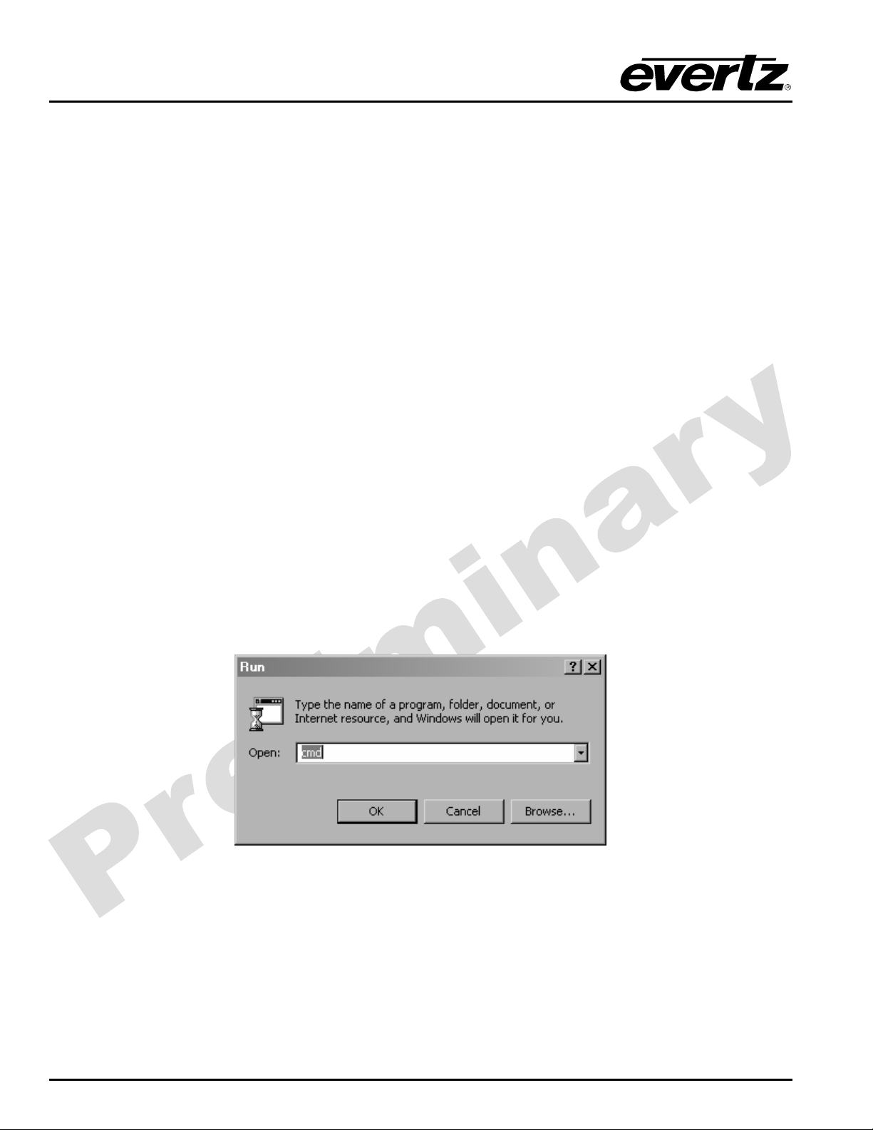
2. Open a DOS window. This can be accomplished by using the run command under the start button,
type “cmd”; see figure below for an example:
Figure 6-2: Opening a DOS Command Window
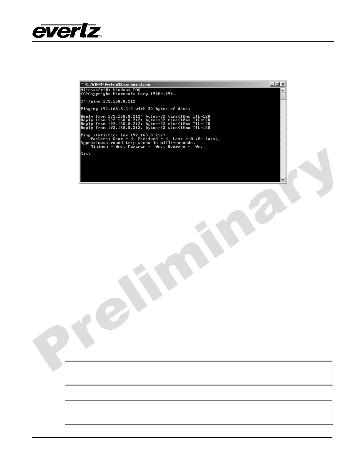
3. “Ping” the IP address of the module being upgraded to confirm that you have a valid network
connection. In the command prompt window type:
the module)
7700TPI-16
Revision 0.2
ping xxx.xxx.xxx.xxx
<Enter> (IP address of
Page 21
7700 MultiFrame Manual
7700TPI VistaLINK Third Party Interface Module
If a proper network connection has been established, a “reply” is displayed on the DOS window. If
there is a faulty network connection, a “Destination Host Unreachable” message is provided. If this
occurs, both IP addresses of the nodes should be verified or the network (Ethernet) cable may be
faulty.
Figure 6-3: Pinging a 7700TPI Module
6.2.1.3. FTP Upgrade
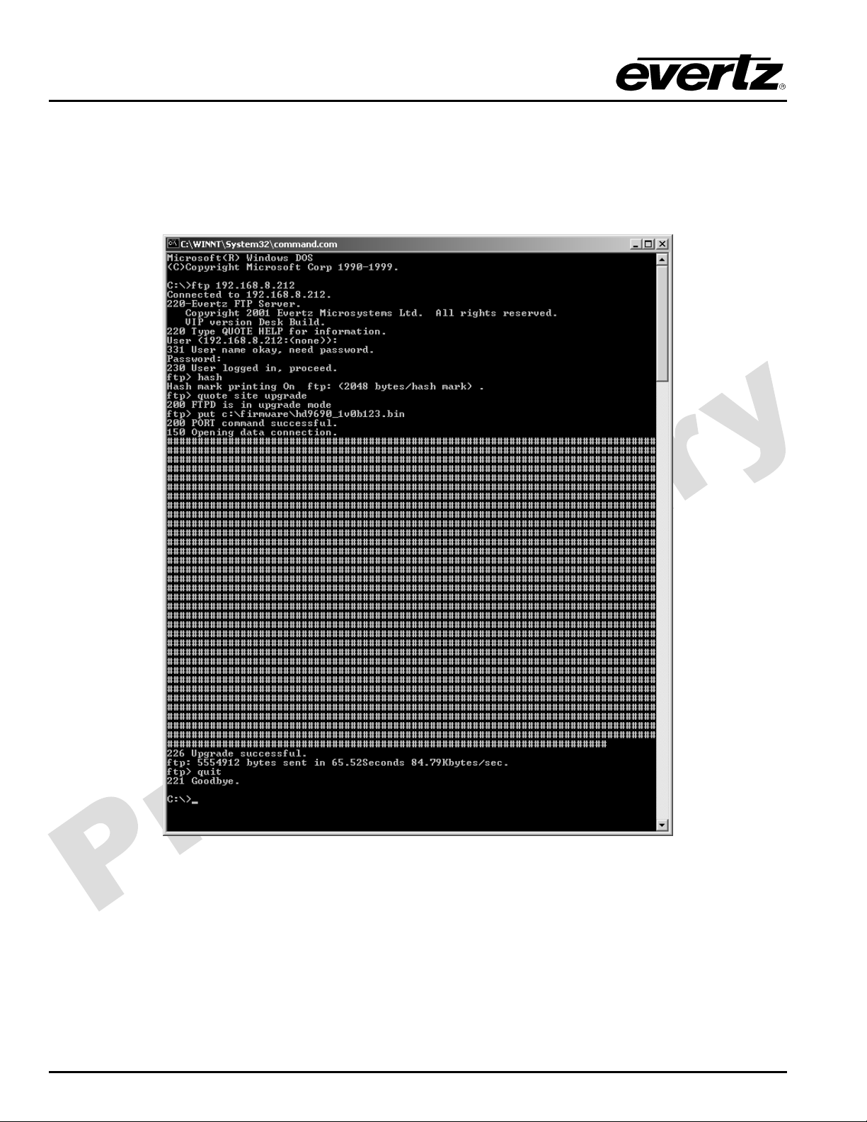
Using the same DOS command prompt from the previous section, apply the following steps to upgrade the
7700TPI module.
1. Obtain the new application code and place it on the local drive of the PC
2. In the command prompt window type:
3. Press the <Enter> key when prompted for a “Username”.
4. Press the <Enter> key when prompted for a “Password”. A message indicating that you logged in
is displayed.
5. At the “FTP>” prompt type
6. At the “FTP>” prompt type
indicating that you are in upgrade mode is displayed.
7. At the “FTP>” prompt type:
(For example: put 7700tpi-1.0.0.bin)
If the application file is not local to where you are performing the ftp, then include
"
the path with the name (For example: put c:\firmware\ 7700tpi-1.0.0.bin)
hash
to turn on the progress indicator during the ftp upload.
quote site upgrade
put “the name of the file.bin”
ftp xxx.xxx.xxx.xxx
to put the unit in upgrade mode. A message
(IP address of the module)
to send the firmware to the unit.
During this time it is mandatory that all power cycles of the unit be avoided. The
"
Revision 0.2
figure below displays a successful FTP session.
7700TPI-17
Page 22
7700 MultiFrame Manual
7700TPI VistaLINK Third Party Interface Module
8. A message indicating the successful connection to the module is displayed
9. File transfer occurs in several seconds, and the DOS window displays the “FTP>” prompt again
10. At the “FTP>” prompt type
quit
to exit the FTP procedure.
7700TPI-18
Figure 6-4: FTP Upgrading a 7700TPI Module
Revision 0.2
Page 23

7700 MultiFrame Manual
7700TPI VistaLINK Third Party Interface Module
6.2.1.4. Completing the FTP Upgrade
At this point the firmware has been accepted by the 7700TPI module. For the new firmware to
take affect, and reboot of the module is required. This can be done by removing the module from
the 7700FR-C frame and re-inserting the module. Please ensure that the 7700TPI module has
been firmly seated into place and proper contact has been made with the rear plate.
6.2.2. Upgrading the Firmware Over an RS-232 Serial Connection
UPGRADE: The UPGRADE jumper J2 located at the front edge of the module, near the serial
port header, is used when firmware upgrades are being done to the module. For
normal operation it should be installed in the RUN position. See the Upgrading
Firmware section in the front of the binder for more information.
To upgrade the firmware in the module pull it out of the frame. Move Jumper J2 into
the UPGRADE position. Install the Upgrade cable provided (located in the vinyl
pouch in the front of this manual) onto header J1 near the card ejector. Re-install
the module into the frame. Run the upgrade as described in the Upgrading
Firmware section in the front of the binder. Once the upgrade is completed, remove
the module from the frame, move J2 into the RUN position, remove the upgrade
cable and re-install the module. The module is now ready for normal operation.
"
6.3. CONTROLLING GPI PULLUP VOLTAGE
Jumper J10, located at the rear of the module, controls whether the GPI inputs and outputs are pulled up
to 5 volts or 12 volts.
GPI SELECT: To pull the GPI inputs and outputs up to 12 volts install this jumper in the position
To pull the GPI inputs and outputs up to 5 volts install this jumper in the position
Note that the baud rate for serial firmware upgrades is 115200 baud.
closest to the rear edge of the module.
closest to the front edge of the module.
Revision 0.2
7700TPI-19
Page 24

7700 MultiFrame Manual
7700TPI VistaLINK Third Party Interface Module
7. VISTALINK® REMOTE MONITORING/CONTROL
7.1. WHAT IS V
VistaLINK
is Evertz’ remote monitoring and configuration platform which operates over an Ethernet
®
ISTA
LINK®?
network using Simple Network Management Protocol (SNMP). SNMP is a standard computer network
protocol that enables different devices sharing the same network to communicate with each other.
VistaLINK
provides centralized alarm management, which monitors, reports, and logs all incoming alarm
®
events and dispatches alerts to all the VLPro Clients connected to the server. Card configuration through
VistaLINK
routines, which reduces the time to configure each module separately. Finally, VistaLINK
PRO can be performed on an individual or multi-card basis using simple copy and paste
®
enables the
®
user to configure devices in the network from a central station and receive feedback that the configuration
has been carried out.
There are 3 components of SNMP:
1. An SNMP manager, also known as a Network Management System (NMS), is a computer running
special software that communicates with the devices in the network. Evertz VistaLINK
®
-C
Configuration Utility graphical user interface (GUI), third party or custom manager software may be
used to monitor and control Evertz VistaLINK
enabled products.
®
1. Managed devices (such as the 7700TPI module), each with a unique address (OID), communicate
with the NMS through an SNMP Agent.
2. A virtual database known as the Management Information Base (MIB) lists all the variables being
monitored and which both the Manager and Agent understand. Please contact Evertz for further
information about obtaining a copy of the MIB for interfacing to a third party Manager/NMS.
7.2. V
ISTA
LINK® MONITORED PARAMETERS
The following parameters can be remotely monitored through the VistaLINK
Parameter Description
Card Type
Serial Number
Firmware Version
GPI Status
Indicates the name of the module
Indicates the serial number of the module
Indicates the card type (e.g. 7700R2X2-HD, 7700R2X2-HES)
Indicated the current state of a GPI
Table 7-1: VistaLINK® Monitored Parameters
7.3. V
ISTA
LINK® CONTROLLED PARAMETERS
The following parameters can be remotely monitored through the VistaLINK
Parameter Description
GPI Trap Enable
GPO State
Sets a filter on the module, to decide whether or not a GPI trap is to be fired
Sets the state of a GPO
Table 7-2: VistaLINK® Controlled Parameters
interface:
®
interface:
®
7700TPI-20
Revision 0.2
Page 25

7700 MultiFrame Manual
7700TPI VistaLINK Third Party Interface Module
7.4. V
Trap Description
GPI
ISTA
LINK® TRAPS
Triggers when a GPI is asserted
Table 7-3: VistaLINK® Traps
Revision 0.2
7700TPI-21
Page 26

7700 MultiFrame Manual
7700TPI VistaLINK Third Party Interface Module
This page left intentionally blank
7700TPI-22
Revision 0.2
 Loading...