

Page 1

7700 MultiFrame Manual
7780DLY-ASI ASI Delay
TABLE OF CONTENTS
1. OVERVIEW.......................................................................................................................................... 1
2. INSTALLATION................................................................................................................................... 3
2.1. ASI CONNECTIONS................................................................................................................... 3
2.2. SDI OUTPUT OVER OSD .......................................................................................................... 3
2.3. GENERAL PURPOSE INPUTS.................................................................................................. 4
3. SPECIFICATIONS............................................................................................................................... 5
3.1. ASI INPUT/OUTPUT................................................................................................................... 5
3.1.1. Asynchronous Serial Interface........................................................................................ 5
3.1.2. Standard Definition Serial Digital Video (OSD)............................................................... 5
3.2. FUNCTIONAL............................................................................................................................. 5
3.3. ELECTRICAL ............................................................................................................................. 5
3.4. PHYSICAL.................................................................................................................................. 5
4. STATUS LEDS.................................................................................................................................... 6
5. CARD EDGE CONTROLS - 7780DLY-ASI......................................................................................... 7
5.1. SELECTING THE OSD VIDEO STANDARD – 7780DLY-ASI................................................... 7
5.2. SELECTING WHETHER THE MODULE WILL BE CONTROLLED FROM THE
LOCAL CONTROLS OR THROUGH THE VISTALINK
6. USING THE ON SCREEN MENU ....................................................................................................... 9
6.1. TOP LEVEL MENU STRUCTURE ........................................................................................... 10
6.1.1. Setting the ASI Delay....................................................................................................11
6.2. CONFIGURING THE MONITORING PARAMETERS.............................................................. 11
6.3. UTILITY MENU......................................................................................................................... 12
7. JUMPERS AND USER CONTROLS................................................................................................. 13
7.1. SELECTING WHETHER LOCAL FAULTS WILL BE MONITORED
BY THE GLOBAL FRAME STATUS........................................................................................ 13
7.2. CONFIGURING THE MODULE FOR FIRMWARE UPGRADES ............................................. 14
INTERFACE – 7780DLY-ASI ........... 8
®
Revision 1.1
Page 2

7700 MultiFrame Manual
7780DLY-ASI ASI Delay
8. VISTALINK® REMOTE MONITORING/CONTROL........................................................................... 15
8.1. WHAT IS VISTALINK®?........................................................................................................... 15
8.2. VISTALINK® MONITORED PARAMETERS ............................................................................ 16
8.3. VISTALINK® CONTROLLED PARAMETERS ......................................................................... 17
8.4. VISTALINK® TRAPS ................................................................................................................ 17
Figures
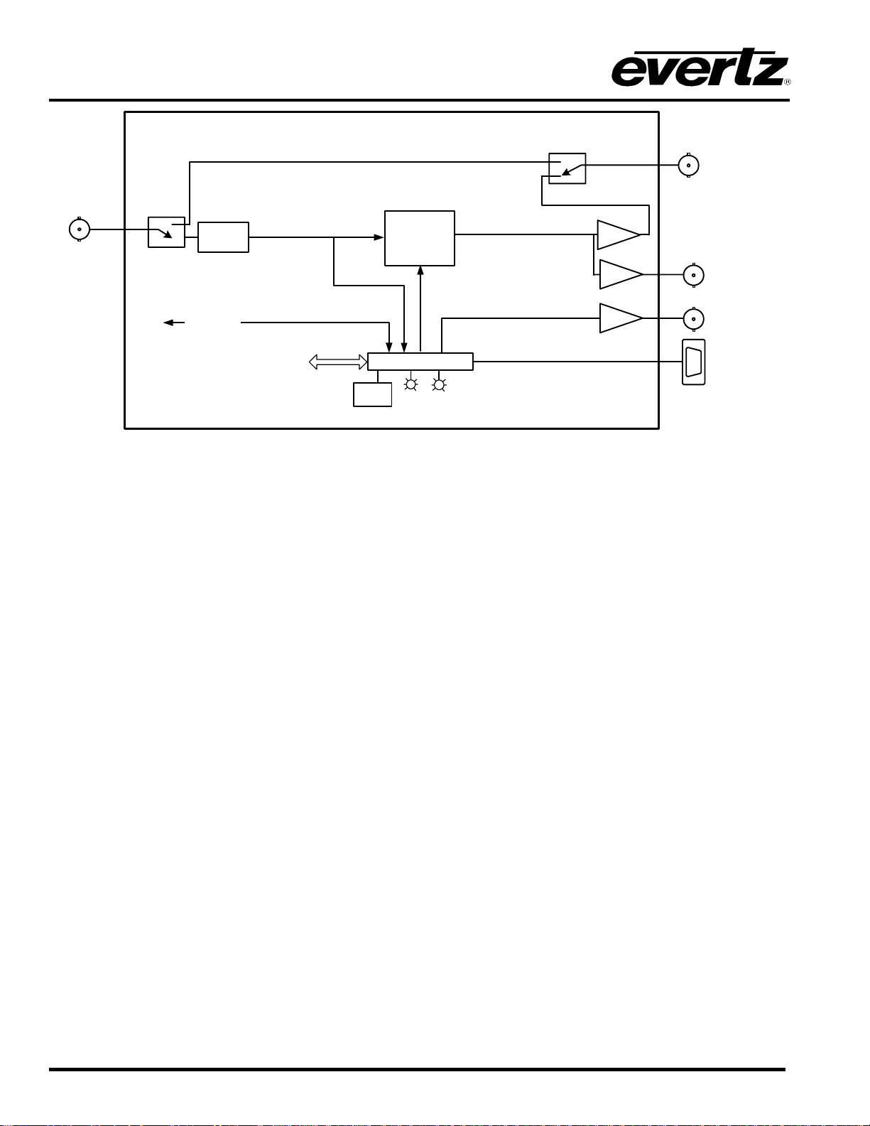
Figure 1-1: 7780DLY-ASI ASI Delay Block Diagram............................................................................................2
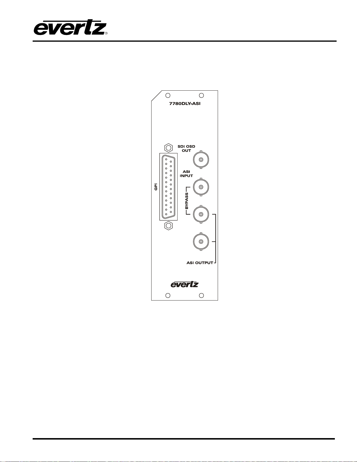
Figure 2-1: 7780DLY-ASI Rear Panel...................................................................................................................3
Figure 7-1: Location of Jumpers on Main Boards...............................................................................................13
Figure 7-2: Location of Jumpers on 7700CC Sub-Module .................................................................................13
Tables
Table 2-1: GPI Connector Pin Definitions.............................................................................................................4
Table 5-1: Overview of DIP Switch Functions – 7780DLY-ASI ............................................................................7
Table 5-2: Video Standard Switch Settings – 7780DLY-ASI ................................................................................7
Table 5-3: VistaLINK® Control Switch Settings – 7780DLY-ASI...........................................................................8
Table 8-1: VistaLINK® Monitored Parameters.....................................................................................................16
Table 8-2: VistaLINK® Controlled Parameters....................................................................................................17
Table 8-3: VistaLINK® Traps...............................................................................................................................17
Revision 1.1
Page 3

7700 MultiFrame Manual
7780DLY-ASI ASI Delay
REVISION HISTORY
REVISION
0.1 Preliminary Version Sep 06
1.0 Updated Table 5-1 Dip Swich Functions, VistaLINK
1.1 Updated VistaLINK section Nov 08
Information contained in this manual is believed to be accurate and reliable. However, Evertz assumes no responsibility for the use thereof nor for
the rights of third parties, which may be effected in any way by the use thereof. Any representations in this document concerning performance of
Evertz products are for informational use only and are not warranties of future performance, either express or implied. The only warranty offered by
Evertz in relation to this product is the Evertz standard limited warranty, stated in the sales contract or order confirmation form.
Although every attempt has been made to accurately describe the features, installation and operation of this product in this manual, no warranty is
granted nor liability assumed in relation to any errors or omissions unless specifically undertaken in the Evertz sales contract or order confirmation.
Information contained in this manual is periodically updated and changes will be incorporated into subsequent editions. If you encounter an error,
please notify Evertz Customer Service department. Evertz reserves the right, without notice or liability, to make changes in equipment design or
specifications.
DESCRIPTION DATE
, and Status Window items Jun 07
®
Revision 1.1
Page 4

7700 MultiFrame Manual
7780DLY-ASI ASI Delay
This page left intentionally blank
Revision 1.1
Page 5

7700 MultiFrame Manual
7780DLY-ASI ASI Delay
1. OVERVIEW
The 7780DLY-ASI is a full function ASI Delay module designed for applications such as: satellite uplink,
redundant path matching, and matching delays in the compressed domain caused by multi-path
compression and distribution.
The 7780DLY-ASI will delay any transport streams with any content (MPEG-2, H.264, VC-1, data, audio,
etc…). It is completely agnostic of the content of the stream.
The 7780DLY-ASI offers up to 16 seconds of delay in 1 ms increments.
Model Video Standard Delay Range Bitrate
7780DLY-ASI DVB ASI
65 µs up to 16
seconds
From 100Kbits/s to
213Mbits/s
The 7780DLY-ASI ASI Delay modules will delay the complete ASI stream bit by bit maintaining any
transport stream timing and ASI packet distribution. The delay can be set in seconds with 1 ms
increments.
With the broadcast environment in mind, the modules feature bypass relay protection to one output. The
7780DLY-ASI ASI Delay modules are housed in a 3RU frame that will hold up to seven 7780DLY-ASI
modules or a 1RU frame that will hold up to three modules.
Features:
• 1 ASI input 100kb/s to 213Mb/s and 2 ASI outputs
• Delay from few bytes to 16 seconds in 1ms increment
• Support 188 and 204 bytes packets (Auto-detect)
• ASI input test includes:
- Sync Byte error and Sync loss detection
- Total Bitrate
- Useful Bitrate
- Null packet Bitrate
- Continuity count error
- List of active PIDs
• Controlled by VistaLINK
• Fully integrated with the industry leading Evertz VistaLINK
PRO or Card Edge
®
PRO NMS system
®
• OSD (On-Screen Display) on SDI output for status and configuration display
• 7 programmable preset delays controllable by GPI and VistaLINK
PRO
®
• Passive bypass for increased safety
Revision 1.1 7780DLY-ASI - 1
Page 6
7700 MultiFrame Manual
7780DLY-ASI ASI Delay
DVB ASI Input
Equalizer
Variabl
e
Delay Buffer
Cable
Driver
DVB ASI Output
(Bypass Protected)
RS232 control
VistaLINK
Interface
Cable
Driver
Cable
Driver
TM
Card
Edge
CPU Control
Module
Input
Status
Present
GPI input 1 to 8
DVB ASI Output
SDI OSD
DB25
Figure 1-1: 7780DLY-ASI ASI Delay Block Diagram
7780DLY-ASI - 2 Revision 1.1
Page 7
7700 MultiFrame Manual
7780DLY-ASI ASI Delay
2. INSTALLATION
The 7780DLY-ASI module comes with a companion rear plate that has 4 BNC connectors and a 25 pin D
connector and occupies two slots in the frame. For information on mounting the rear plate and inserting
the module into the frame see section 3 of the 7700FR chapter.
Figure 2-1: 7780DLY-ASI Rear Panel
2.1. ASI CONNECTIONS
ASI INPUT: Input BNC connector for the DVB ASI signal.
ASI OUTPUT (VIDEO OUTPUT): Two BNC ASI outputs are provided. Output 1 is protected by a
bypass relay, which will activate in the event of power loss to the module. The
remaining output is not bypass protected.
2.2. SDI OUTPUT OVER OSD
SDI OSD OUT: This BNC is used to connect a SDI video monitor to view the on screen display.
Revision 1.1 7780DLY-ASI - 3
Page 8

7700 MultiFrame Manual
7780DLY-ASI ASI Delay
2.3. GENERAL PURPOSE INPUTS
A 25 pin D connector labeled GPI contains 8 GPI inputs. The connector pinout is shown in Table 2-1.
Pin # Name Description
1 - Not used
2 - Not used
3 GPI 0 Bypass Relay Enable
4 GPI 1 Preset 1
5 - Not used
6 - Not used
7 - Not used
8 - Not used
9 - Not used
10 - Not used
11 GPI 2 Preset 2
12 GPI 3 Preset 3
13 GPI 4 Preset 4
14 GPI 6 Preset 6
15 GPI 7 Preset 7
16 - Not used
17 - Not used
18 - Not used
19 - Not used
20 - Not used
21 GND Ground
22 - Not used
23 - Not used
24 - Not used
25 GPI 5 Preset 5
Shell Ground
Table 2-1: GPI Connector Pin Definitions
7780DLY-ASI - 4 Revision 1.1
Page 9

3. SPECIFICATIONS
3.1. ASI INPUT/OUTPUT
3.1.1. Asynchronous Serial Interface
Standard: DVB TR101 891, 270Mb/s
Number of Inputs: 1
Number of Outputs: 1 (with relay bypass)
Bitrate: 100kb/s to 213Mb/s
3.1.2. Standard Definition Serial Digital Video (OSD)
Number of Outputs: 1
Connector: BNC per IEC 61169-8 Annex A
Signal Level: 800mV nominal
DC Offset: 0V ±0.5V
Rise and Fall Time: 200ps nominal (HD), 740ps nominal (SD)
Overshoot: < 10% of amplitude
Return Loss: > 15dB up to 1.5Gb/s (HD)
Wide Band Jitter: < 0.2 UI
7700 MultiFrame Manual
7780DLY-ASI ASI Delay
3.2. FUNCTIONAL
Minimum Delay:
7780DLY-ASI: 5 MPEG-2 packets
Maximum Delay:
7780DLY-ASI: 16 sec independent of the ASI bitrate
3.3. ELECTRICAL
Voltage: + 12VDC
Power: 20 watts
EMI/RFI: Complies with FCC Part 15, class A devices.
Complies with EU EMC directive.
3.4. PHYSICAL
7700 frame mounting:
Number of slots: 2
7701 frame mounting:
Number of slots: 1
Stand Alone Enclosure:
Dimensions: 14 “ L x 4.5 “ W x 1.9 “ H
(355 mm L x 114 mm W x 48 mm H)
Weight: approx. 1.5 lbs. (0.7 Kg)
Revision 1.1 7780DLY-ASI - 5
Page 10

7700 MultiFrame Manual
7780DLY-ASI ASI Delay
4. STATUS LEDS
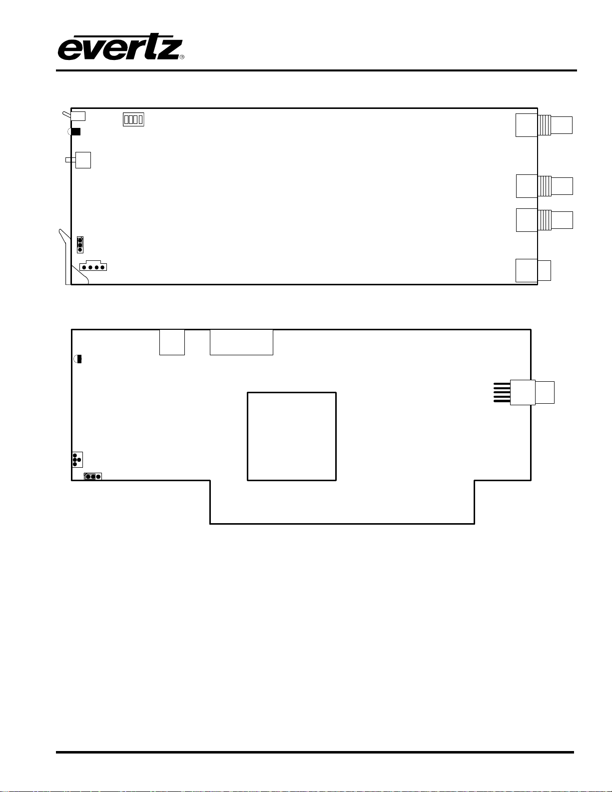
The 7780DLY-ASI has 2 LED Status indicators on the main circuit board and 1 indicator on the submodule to show operational status of the card at a glance. Figure 7-1 and Figure 7-2 shows the location of
the LEDs and card edge controls.
Two large LEDS on the front of the main board indicate the general health of the module:
LOCAL FAULT: This Red LED indicates poor module health and will be ON during the absence of a
valid input signal or if a local input power fault exists (i.e.: a blown fuse). The LOCAL
FAULT indication can also be reported to the frame through the FRAME STATUS
jumper.
MODULE OK: This Green LED indicates good module health. It will be ON when the board power
is good and the module detects a valid input.
SIGNAL PRESENT: This Green LED will be ON when there is a valid ASI signal present at the module
input.
One LED on the sub-module (7700CC) indicates the presence of the ASI TS input.
7780DLY-ASI - 6 Revision 1.1
Page 11
7700 MultiFrame Manual
7780DLY-ASI ASI Delay
5. CARD EDGE CONTROLS - 7780DLY-ASI
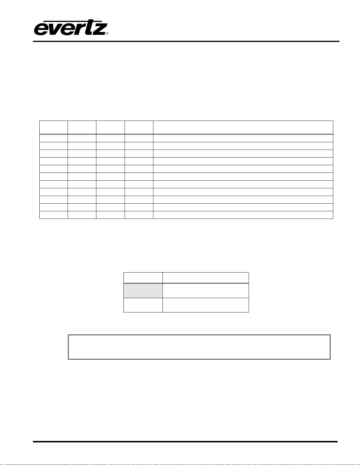
The 7780DLY-ASI module is equipped with a 4 position DIP switch on the top edge of the card to allow the
user to select various functions. All positions are assigned sequentially such that the DIP switch 1 is
located farthest from the front of the card. Table 5-1 gives an overview of the DIP switch functions for the
7780DLY-ASI. Sections 5.1 and 5.2 describe the assigned DIP switch functions. The On (closed) position
is down, or closest to the printed circuit board. The Off (open) position is up, or farthest from the printed
circuit board. There is also a toggle switch and pushbutton which are used to navigate the on screen
menu. (See section 6).
DIP 1 DIP 2 DIP 3 DIP 4 Setting
0 0 0 0 525i/59.94
0 0 0 1 Not used
0 0 1 0 Not used
0 0 1 1 Not used
0 1 0 0 Not used
0 1 0 1 Not used
0 1 1 0 Not used
0 1 1 1 Not used
1 0 0 0 625i/60
1 0 0 1 Not used
1 1 1 1 VistaLINK® remote ON (otherwise, VistaLINK® remote OFF)
Table 5-1: Overview of DIP Switch Functions – 7780DLY-ASI
5.1. SELECTING THE OSD VIDEO STANDARD – 7780DLY-ASI
DIP switch 1 is used to select the video standard for the SDI OSD output.
DIP 1 Video Format
Off 525 lines (525i/59.94)
On 625 lines (625i/50)
Table 5-2: Video Standard Switch Settings – 7780DLY-ASI
"
Note that when VistaLINK
through software.
is enabled, the control of the OSD format is done
®
Revision 1.1 7780DLY-ASI - 7
Page 12
7700 MultiFrame Manual
7780DLY-ASI ASI Delay
5.2. SELECTING WHETHER THE MODULE WILL BE CONTROLLED FROM THE
LOCAL CONTROLS OR THROUGH THE VISTALINK
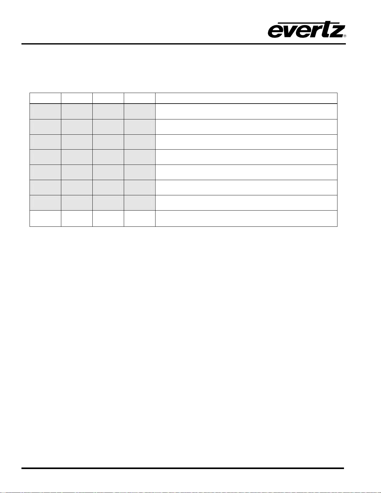
DIP switch 2, 3, 4 selects whether the module will be controlled from the local user controls or through the
VistaLINK
interface.
®
DIP 1 DIP 2 DIP 3 DIP 4 VISTALINK
Off Off Off Off 525i/59.94
ON Off Off Off 625i/50
Off Off On Off Not used
Off Off On On Not used
On On Off Off Not used
On On Off On Not used
On On On Off Not used
INTERFACE – 7780DLY-ASI
®
CONTROL
®
On On On On
Table 5-3: VistaLINK® Control Switch Settings – 7780DLY-ASI
The card functions are controlled through the VistaLINK
interface and local menu (See section 8)
®
7780DLY-ASI - 8 Revision 1.1
Page 13

7700 MultiFrame Manual
7780DLY-ASI ASI Delay
6. USING THE ON SCREEN MENU
An On Screen Display (OSD) is used to configure many of the module’s parameters. The three position,
return to center, toggle switch and momentary pushbutton located on the front edge of the module are
used to navigate the OSD setup menus and configure the cards various controls.
The OSD menu system is always present on the SDI output. You can use the toggle switch to move up
and down the list of available sub-menus. An arrow (>) moves up and down the left hand side of the menu
items to indicate which item you are currently selecting. Once the arrow is on the desired item, press the
pushbutton to select the next menu.
On all menus, there is a selectable item Done. Selecting Done will take you to the previous menu (the one
that was used to get into the menu). If you are at the top level of the menu tree then selecting Done will
exit the OSD menu and return to the main status display.
Once you are in a sub-menu, there may be another menu level, or there may be a list of parameters to
adjust. If there is another set of menu options, use the toggle switch to select the next choice with the
same procedure as in the main menu.
If there is a list of parameters to adjust, use the toggle switch to move up or down to the desired parameter
and press the pushbutton. The arrow will move to the right hand side (<) indicating that you can now
adjust the parameter. Using the toggle switch, adjust the parameter to its desired value. If the parameter
is a numerical value, the number will increase if you lift the toggle switch and decrease if you push down
on the toggle switch. If the parameter contains a list of choices, you can cycle through the list by pressing
the toggle switch in either direction.
When you have stopped at the desired value, depress the pushbutton. This will update the parameter with
the selected value and move the arrow back to the left side of the parameter list. Continue selecting and
adjusting other parameters or use the Done commands to return to the next higher menu level.
"
NOTE: THERE IS NO PICTURE DISPLAYED ON THE SDI OSD AS THE INPUT OF
THE 7780DLY-ASI IS A COMPRESSED STREAM AND THE CARD DOES NOT HAVE
AN MPEG-2 DECODER.
Revision 1.1 7780DLY-ASI - 9
Page 14

7700 MultiFrame Manual
7780DLY-ASI ASI Delay
6.1. TOP LEVEL MENU STRUCTURE
When the module is running, the OSD will show the status of the input. The status window displays the
following:
SIGNAL ASI input presence status.
TOTAL TS BITRATE A measurement of the total Bitrate of the input stream.
NULL PACKETS A measurement of the null packet Bitrate in the input stream.
USEFUL BITRATE A measurement of the non null packet Bitrate in the input stream.
DETECTED TS
PACKET LENGTH
MODULE STATUS Displays the module health status.
ASI DELAY Identifies the current settings of the ASI delay.
SYNC BYTE ERROR
COUNTER
MAX BITRATE
THRESHOLD ERROR
MIN BITRATE
THRESHOLD ERROR
TOTAL CONTINUATY
COUNT ERRORS
ACTIVE PID COUNTS Defines a total of all active PID’s detected.
OSD VIDEO
STANDARD
Detected packet length on the input stream (188 or 204 bytes).
A running count of the number of sync errors since the last stream
synchronization or reset.
Indicates whether the max total Bitrate threshold has been exceeded.
Indicates whether the min total Bitrate threshold has been exceeded.
A running count of the number of continuity errors across all PIDs since the
last stream synchronization or reset.
Video standard of the SD OSD output.
VistaLINK® CONTROL Indicates whether remote control of the module is enabled.
7780DLY-ASI - 10 Revision 1.1
Page 15
7700 MultiFrame Manual
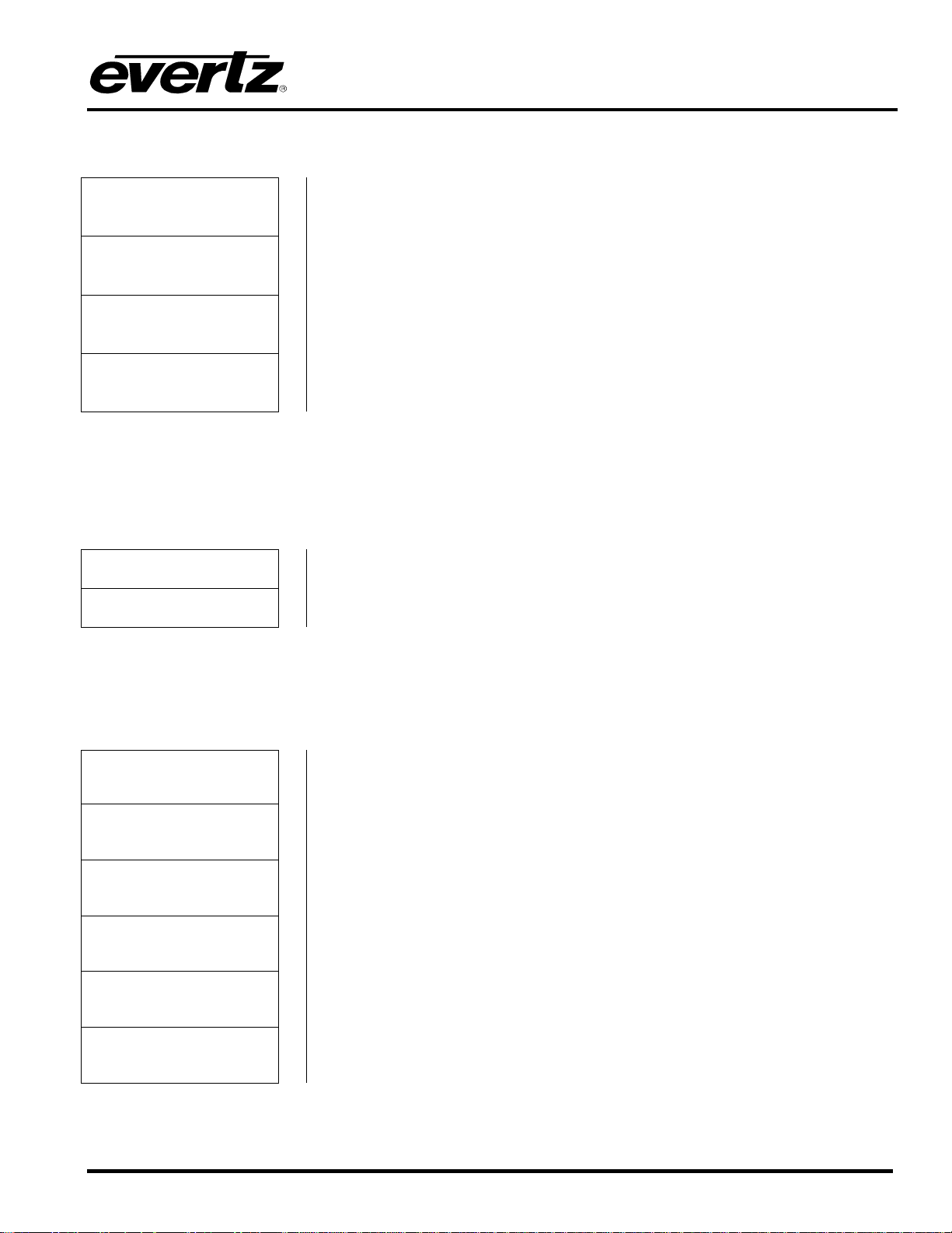
The following is a brief description of the top level of the menu tree that appears when you enter the on
screen menu. Selecting one of these items will take you down into the next menu level.
7780DLY-ASI ASI Delay
SET ASI DELAY
MONITORING
PARAMETER
UTILITY Enter the utility menu.
DONE Exit On Screen Menu System.
6.1.1. Setting the ASI Delay
The SET ASI DELAY menu item allows the user to set the ASI delay. The maximum delay is
approximately 16 seconds. The ASI delay is set using millisecond increments. Each time the pushbutton
is pressed to accept a new value of delay, the new ASI delay will be implemented immediately.
DELAY Sets the amount of ASI delay in seconds and milliseconds.
DONE Return to main menu.
Set the amount of delay.
Setup monitoring parameters and reset parameters.
6.2. CONFIGURING THE MONITORING PARAMETERS
The MONITORING PARAMETER menus are used to set measurement thresholds. The chart below
shows the items available in the Reference Phase menu.
MAX BITRATE
THRESHOLD
MIN BITRATE
THRESHOLD
TS PACKET LENGTH Set to auto-detect or force to 188 or 204 bytes per packet.
TIMEOUT WINDOW Sets the timeout period to report sync byte errors.
RESET ERROR Reset all error counters.
DONE Return to main menu.
Sets the maximum Bitrate threshold above which an error will be generated.
Sets the minimum Bitrate threshold below which an error will be generated.
Revision 1.1 7780DLY-ASI - 11
Page 16

7700 MultiFrame Manual
7780DLY-ASI ASI Delay
6.3. UTILITY MENU
BYPASS RELAY
OFF/ON
RECALL PRESET Recalls one of the 7 delay presets.
SAVE PRESET Save current settings into one of the 7 delay presets.
FACTORY RESET Reset the module to factory defaults.
VISTALINK STATUS Enable or disable VistaLINK® control.
FIRMWARE VERSION Displays the firmware version installed in the module.
DONE Return to the main menu.
Activates bypass from input to the first output BNC. The module will not
detect an input in this condition.
7780DLY-ASI - 12 Revision 1.1
Page 17
7. JUMPERS AND USER CONTROLS
1234
MODULE STATUS
EVERTZ (A) 7700SP3
FRAME
STATUS
ON
OFF
J22
7700 MultiFrame Manual
7780DLY-ASI ASI Delay
SFF POWER +12V
GND
EVERTZ (B) 7700CC
LD2 SIGNAL PRESENT
J14
J15
Run
Upgrade
Figure 7-1: Location of Jumpers on Main Boards
Figure 7-2: Location of Jumpers on 7700CC Sub-Module
7.1. SELECTING WHETHER LOCAL FAULTS WILL BE MONITORED
BY THE GLOBAL FRAME STATUS
FRAME STATUS: The FRAME STATUS jumper J22 located at the front of the main module
determines whether local faults (as shown by the Local Fault indicator) will be
connected to the 7700FR frame's global status bus.
To monitor faults on this module with the frame status indicators (on the Power
Supplies FRAME STATUS LED's and on the Frame's Fault Tally output) install this
jumper in the On position. (Default)
When this jumper is installed in the Off position, local faults on this module will not
be monitored.
Revision 1.1 7780DLY-ASI - 13
Page 18

7700 MultiFrame Manual
7780DLY-ASI ASI Delay
7.2. CONFIGURING THE MODULE FOR FIRMWARE UPGRADES
UPGRADE: The UPGRADE jumper J15 located near the front of the sub-module is used when
firmware upgrades are being done to the module. For normal operation it should be
installed in the RUN position. See the Upgrading Firmware chapter in the front of
the binder for more information.
To upgrade the firmware in the module, pull it out of the frame. Move Jumper J15 to
the UPGRADE position. Install the Upgrade cable provided (located in the vinyl
pouch in the front of this manual) onto header J14 at the card edge. Re-install the
module into the frame. Perform the upgrade as described in the Upgrading
Firmware chapter. Once the upgrade is complete, remove the module from the
frame, move J15 to the RUN position, remove the upgrade cable and re-install the
module. The module is now ready for normal operation.
7780DLY-ASI - 14 Revision 1.1
Page 19

8. VISTALINK® REMOTE MONITORING/CONTROL
8.1. WHAT IS VISTALINK®?
7700 MultiFrame Manual
7780DLY-ASI ASI Delay
VistaLINK
is Evertz’s remote monitoring and configuration platform which operates over an Ethernet
®
network using Simple Network Management Protocol (SNMP). SNMP is a standard computer network
protocol that enables different devices sharing the same network to communicate with each other.
VistaLINK
provides centralized alarm management, which monitors, reports, and logs all incoming alarm
®
events and dispatches alerts to all the VLPro Clients connected to the server. Card configuration through
VistaLINK
routines, which reduces the time to configure each module separately. Finally, VistaLINK
PRO can be performed on an individual or multi-card basis using simple copy and paste
®
enables the
®
user to configure devices in the network from a central station and receive feedback that the configuration
has been carried out.
There are 3 components of SNMP:
1. An SNMP manager, also known as a Network Management System (NMS), is a computer running
special software that communicates with the devices in the network. Evertz VistaLINK
®
-C
Configuration Utility graphical user interface (GUI), third party or custom manager software may be
used to monitor and control Evertz VistaLINK
enabled products.
®
2. Managed devices each with a unique address (OID), communicate with the NMS through an SNMP
Agent. The 7780DLY-ASI communicates directly with the manager using its internal Agent.
3. A virtual database known as the Management Information Base (MIB) lists all the variables being
monitored, which both the Manager and Agent understand. Please contact Evertz for further
information about obtaining a copy of the MIB for interfacing to a third party Manager/NMS.
Revision 1.1 7780DLY-ASI - 15
Page 20

7700 MultiFrame Manual
7780DLY-ASI ASI Delay
8.2. VISTALINK® MONITORED PARAMETERS
The following parameters can be remotely monitored through the VistaLINK
Parameter Description
ASI Delay
Bypass relay status
Local remote mode
Data bitrate
Null packet data rate
Useful data rate
Packet length
Number of PIDs
Continuity count error counter
The current ASI delay.
The current relay status.
The status of the VistaLINK
DIP switch.
®
The value of the input ASI bitrate.
The value of the input null packet rate.
The value of the useful input data rate.
The packet length of the input stream.
The number of active PIDs on the input.
The value of the number of continuity count errors reported.
interface.
®
Module Status
Input ASI Present
Max Bitrate threshold
Min Bitrate threshold
Indicates module status.
Indicates the status of the ASI input signal.
(The state of the ASI PRESENT LED)
Indicates the set threshold for maximum bitrate.
Indicates the set threshold for minimum bitrate.
Table 8-1: VistaLINK® Monitored Parameters
7780DLY-ASI - 16 Revision 1.1
Page 21
7700 MultiFrame Manual
7780DLY-ASI ASI Delay
8.3. VISTALINK
CONTROLLED PARAMETERS
®
Parameter Description
ASI Delay
Bypass relay
Preset recall
Preset store
Packet length
OSD video standard
Max Bitrate threshold
Min Bitrate threshold
Timeout Window
Reset Errors
Set ASI delay.
Set bypass relay mode.
Recall a preset.
Store current configuration into preset.
Force packet length.
Set video standard for the OSD.
Indicates the set threshold for maximum bitrate.
Indicates the set threshold for minimum bitrate.
Set timeout period to report sync byte errors.
Reset all error counters.
Table 8-2: VistaLINK® Controlled Parameters
8.4. VISTALINK
The following traps can be controlled through the VistaLINK
TRAPS
®
interface. Each trap will indicate a fault
®
condition when its value is True.
Parameter Description
Module Status
Input ASI Present
Max Bitrate threshold
Min Bitrate threshold
Continuity count error
Sync byte error
Indicates good module health and the presence of a valid ASI
input signal. (The state of the MODULE OK LED)
Indicates the presence of a valid ASI input signal.
(The state of the ASI PRESENT LED)
Indicates the max bitrate threshold that has been exceeded.
Indicates the min bitrate threshold that has not been exceeded.
Indicates the module detected continuity count error.
Indicates the module detected sync byte error.
Transport Stream Sync Loss
Indicates the module detected transport stream sync loss.
Table 8-3: VistaLINK® Traps
Revision 1.1 7780DLY-ASI - 17
Page 22

7700 MultiFrame Manual
7780DLY-ASI ASI Delay
This page left intentionally blank
7780DLY-ASI - 18 Revision 1.1
 Loading...