

Page 1

High Density Modular Audio R outer
USER MANUAL
© Copyright 2010 - 2016
EVERTZ MICROSYSTEMS LTD.
5292 John Lucas Drive
Burlington, Ontario
Canada L7L 5Z9
Phone: 905-335-3700
Sales: [email protected] Fax: 905-335-3573
Tech Support: [email protected] Fax: 905-335-7571
Web Page: http://www.evertz.com
Version 1.8, February 2016
The material contained in this manual consists of information that is the property of Evertz Microsystems and is intended solely for
the use of purchasers of the EMR. Evertz Microsystems expressly prohibits the use of this manual for any purpose other than the
operation of the EMR. Due to ongoing research and development, features and specifications in this manual are subject to
change without notice.
All rights reserved. No part of this publication may be reproduced without the express written permission of Evertz Microsystems
Ltd. Copies of this manual can be ordered from your Evertz dealer or from Evertz Microsystems.
Page 2
The lightning flash with arrowhead symbol within an equilateral triangle is
important operating and maintenance (i.e.: servicing)
WARNING:
EXPOSE THIS
APPARATUS TO RAIN OR MOISTURE
WARNING:
EXPOSE THIS EQUIPMENT TO DRIPPING OR SPLASHING AND ENSURE THAT NO
OBJECTS FILLED WITH LIQUIDS, SUCH AS VASES, ARE PLACED ON THE EQUIPMENT
WARNING:
TO COMPLETELY DISCONNECT THIS EQUIPMENT FROM THE AC MAINS, DISCONNECT
THE POWER SUPPLY CORD PLUG FROM THE AC RECEPTACLE
WARNING:
THE MAINS PLUG OF THE POWER SUPPLY CORD SHALL REMAIN READILY OPERABLE
IMPORTANT SAFETY INSTRUCTIONS
intended to alert the user to the presence of un-insulated, dangerous voltage
within the product’s enclosure that may be of sufficient magnitude to constitute
a risk of electric shock to persons.
The exclamation point within an equilateral triangle is intended to alert the user
to the presence of
instructions in the literature accompanying the product.
• Read these instructions.
• Keep these instructions.
• Heed all warnings.
• Follow all instructions.
• Don’t use this apparatus near water.
• Clean only with a dry cloth.
• Don’t block any ventilation openings.
• Install in accordance with the manufacturer’s instructions.
• Don’t install near any heat sources such as radiators, heat registers, stoves, or other
apparatuses (including amplifiers) that produce heat.
• Don’t defeat the safety purpose of the polarized or grounding-type plug. A polarized plug has
two blades with one wider than other. A grounding-type plug has two blades and a third
grounding prong. The wide blade or third prong is provided for your safety. If the plug provided
does not fit into your outlet, consult an electrician to replace the obsolete outlet.
• Protect the power cord from being walked on or pinched, particularly at plugs, convenience
receptacles, and the point where they exit from the apparatus.
• Only use attachments/accessories specified by the manufacturer
• Unplug this apparatus during lightning storms, or when unused for long periods of time.
• Refer all servicing to qualified service personnel. Servicing is required when the apparatus has
been damaged in any way, such as damage to the power-supply cord or plug, contact with
liquid (or any object small enough to enter the apparatus), exposure to rain or moisture, drop
damage, or upon experiencing any abnormal operation.
TO REDUCE THE RISK OF FIRE OR ELECTRIC SHOCK, DO NOT
DO NOT
Page 3

. Irreversible eye damage can occur in a
WARNING
Never look directly into an optical fiber
matter of milliseconds.
Page 4

INFORMATION FOR USERS IN EUROP E
This equipment with the CE marking complies with the EMC Directive (89/336/EEC) and the Low Voltage
Directive (73/23/EEC) issued by the Commission of the European Community.
Compliance with these directives implies conformity to the following European standards:
• EN60065 Product Safety
• EN55103-1 Electromagnetic Interference Class A (Emission)
• EN55103-2 Electromagnetic Susceptibility (Immunity)
This equipment has been tested and found to comply with the limits for a Class A digital device, pursuant
to the European Union EMC directive. These limits are designed to provide reasonable protection against
harmful interference when the equipment is operated in a commercial environment. This equipment
generates, uses, and can radiate radio frequency energy and, if not installed and used in accordance with
the instruction manual, may cause harmful interference to radio communications. Operation of this
equipment in a residential area is likely to cause harmful interference, in which case the user will be
required to correct the interference at his/her own expense.
INFORMATION FOR USERS IN THE U.S.A.
FCC Class A Digital Device or Peripheral
This equipment has been tested and found to comply with the regulations for a Class A digital device,
pursuant to Part 15 of the FCC Rules. These limits are designed to provide reasonable protection against
harmful interference when the equipment is operated in a commercial environment. This equipment
generates, uses, and can radiate radio frequency energy and, if not installed and used in accordance with
the instruction manual, may cause harmful interference to radio communications. Operation of this
equipment in a residential area is likely to cause harmful interference, in which case the user will be
required to correct the interference at his/her own expense.
WARNING
Changes or modifications not expressly approved by Evertz Microsystems Ltd. could void the user’s
authority to operate the equipment.
Use of unshielded plugs or cables may cause radiation interference. Properly shielded interface cables
with the shield connected to the chassis ground of the device must be used.
Page 5

EMR User's Guide
High Density Modular Audio Router (AES, Analog, MADI, TimeCode, Data)
REVISION HISTORY
REVISION DESCRIPTION DATE
0.1 Preliminary Release Aug 2010
1.0 First Release Sep 2010
1.1 Removed references to 3000PS-FM and 3000PS-QT-FM.
Updates made in sections 2.2 & 2.3. Nov 2010
1.2 Corrections made to Delay (+DLY) section Nov 2010
1.3 Added EMR-ADMX-16X16, EMR-IP16-MADI, EMR-OP16-MADI. Oct 2011
Added more information for LTC and data port routers. Updated VistaLINK®
Screens and descriptions.
1.3.1 Updated Electrical specification May 2013
1.4 Updates throughout Aug 2013
1.5 Added EMR-ADMX-16X16/A and EMR-ADMX-48X48 Dec 2013
1.6 Added Section 9: Appendix A – ADMX-16X16A and ADMX-48X48 Jan 2014
Redundancy Setup
1.7 Updated Images Jun 2015
1.8 Added EMR-IO8-MADI Feb 2016
Updated EMR- ADMX-16X16A and ADMX-48X48 Redundancy Setup
Information cont ained in this m anual is believed to be accura te and reli able. Ho wever, Evert z assumes no responsi bility for the use thereof, nor for t he rights of thi rd
parties, which m ay be affected in an y wa y by the u se th ereof. A ny repr esent ations i n this documen t conc erning p erforma nce of Evertz prod ucts a re for i nformati onal
use only and are not warra nti e s of future performance, ei t he r e xpressed or implied. The o nly warranty offere d b y Eve rt z in r ela ti on t o this p ro duc t i s the E v ert z standard
limited warranty, stated in the sales contract or order confirmation form.
Although every att empt ha s bee n mad e to ac curately describe the f eat ures, i nstall atio n and oper ation of thi s pr oduc t in t his ma nual , no warra nty i s gra nted nor l iabil ity
assumed in relatio n t o an y er ro rs or omissions unl ess specifically und er tak en in the Evertz sales contract or orde r c o nfi rm ati on. Information contain ed in this manual is
periodically updat ed and changes will be incorporate d into subseque nt editions. If you encounter an erro r, please notif y Evertz Cust omer Ser vice de partm ent. Evert z
reserves the right, without notice or liability, to make changes in equipment design or specifications.
Revision 1.8
Page 6

EMR User’s Guide
High Density Modular Audio Router (AES, Analog, MADI, TimeCode, Data)
This page left intentionally blank
Revision 1.8
Page 7

EMR User's Guide
High Density Modular Audio Router (AES, Analog, MADI, TimeCode, Data)
TABLE OF CONTENTS
1. OVERVIEW ................................................................................................................................... 1
1.1. FEATURES & BENEFITS ..................................................................................................... 2
1.2. SIGNAL TYPES .................................................................................................................... 2
2. COMPONENT OVERVIEW ........................................................................................................... 3
2.1. EMR FRAME ........................................................................................................................ 3
2.2. EMR I/O MODULES .............................................................................................................. 6
2.2.1. EMR-IP96 (48)-AESU (B) AES Audio Input Module ................................................... 6
2.2.1.1. Unbalanced AES Input Rear Panel.............................................................. 7
2.2.1.2. Balanced AES Input Rear Panel .................................................................. 9
2.2.1.3. Balanced AES Input D50 Connector – Pin Out .......................................... 10
2.2.1.4. Front Card Edge Controls and LEDs ......................................................... 11
2.2.1.5. Configuration and Monitoring Menu ........................................................... 12
2.2.2. EMR-OP96 (48)-AESU (B) AES Audio Output Module ............................................ 13
2.2.2.1. Unbalanced AES Output Rear Panel ......................................................... 13
2.2.2.2. Balanced AES Output Rear Panel ............................................................. 15
2.2.2.3. Balanced AES Output D50 Connector – Pin Out ....................................... 16
2.2.2.4. Front Card Edge Controls and LEDs ......................................................... 17
2.2.2.5. Configuration and Monitoring Menu ........................................................... 18
2.2.3. EMR-IP48-AA Analog Audio Input Module ............................................................... 23
2.2.3.1. Analog Audio D50 Connector – Pin Out .................................................... 25
2.2.3.2. Front Card Edge Controls and LEDs ......................................................... 25
2.2.3.3. Configuration and Monitoring Menu ........................................................... 27
2.2.4. EMR-OP48-AA Analog Audio Output Module .......................................................... 28
2.2.4.1. Analog Audio D50 Connector – Pin Out .................................................... 30
2.2.4.2. Front Card Edge Controls and LEDs ......................................................... 31
2.2.4.3. Configuration and Monitoring Menu ........................................................... 32
2.2.5. EMR-ADMX-16X16/A, EMR-ADMX-48X48 and 3000ADMX-16X16
Crosspoint Modules ................................................................................................. 38
2.2.5.1. Front Card Edge Controls and LEDs ......................................................... 39
2.2.5.2. EMR-ADMX-48X48 and EMR-ADMX-16X16A User Commands: .............. 40
2.2.6. EMR-IP16-MADI and 3000MADI16-TDM4 MADI Input Modules .............................. 41
2.2.6.1. Front Card Edge Controls and LEDs ......................................................... 42
2.2.6.2. Configuration and Monitoring Menu ........................................................... 43
2.2.7. EMR-OP16-MADI and 3000TDM4-MADI16 MADI Output Modules ......................... 43
2.2.7.1. Front Card Edge Controls and LEDs ......................................................... 45
2.2.7.2. Configuration and Monitoring Menu ........................................................... 46
2.2.8. EMR-IP96 (48)-LTC Time Code Input Module ......................................................... 46
2.2.8.1. LTC Input D50 Connector – Pin Out .......................................................... 48
2.2.8.2. Front Card Edge Controls and LEDs ......................................................... 49
2.2.8.3. Configuration and Monitoring Menu ........................................................... 50
2.2.9. EMR-OP96 (48)-LTC TimeCode Output Module ...................................................... 51
2.2.9.1. LTC Output D50 Connector – Pin Out ....................................................... 53
2.2.9.2. Front Card Edge Controls and LEDs ......................................................... 54
TABLE OF CONTENTS Revision 1.8 Page i
Page 8

EMR User's Guide
High Density Modular Audio Router (AES, Analog, MADI, TimeCode, Data)
2.2.9.3. Configuration and Monitoring Menu ........................................................... 55
2.2.10. EMR-PR48 Data Module ......................................................................................... 57
2.2.10.1. Data Port D50 Connector – Pin Out .......................................................... 59
2.2.11. EMR-PR48-A Data Module ...................................................................................... 65
2.2.11.1. Learn Modes ............................................................................................. 65
2.2.11.2. Special Modes ........................................................................................... 66
2.2.11.3. Configuration and Monitoring Menu ........................................................... 67
2.2.11.4. Status Signal ............................................................................................. 68
2.2.11.5. Data Port D50 Connector – Pin Out .......................................................... 68
2.2.11.6. Multicard Systems ..................................................................................... 73
2.2.11.7. Front Card Edge Control and LEDs ........................................................... 78
2.2.12. EMR-IO8-MADI ....................................................................................................... 80
2.3. INSTALLING AND REMOVING THE MODULES ............................................................... 82
2.3.1. Installing the Module Rear Plate .............................................................................. 82
2.3.2. Opening and Closing the Front Panel ...................................................................... 82
2.3.3. Installing a Module ................................................................................................... 83
2.3.4. Removing a Module ................................................................................................. 83
2.4. MOUNTING ........................................................................................................................ 83
2.5. COOLING ........................................................................................................................... 83
2.5.1. Fan Exhaust ............................................................................................................ 84
2.6. SERVICING INSTRUCTIONS ............................................................................................. 84
2.6.1. Changing the Fuses ................................................................................................. 84
2.6.2. Replacing the Power Supply .................................................................................... 85
2.7. POWER .............................................................................................................................. 87
2.7.1. Connecting the Power ............................................................................................. 87
2.7.2. Turning the Power On and Off ................................................................................. 88
2.7.3. Power Supply Status Indicators ............................................................................... 88
2.8. FRAME STATUS FAULT CONDITIONS ............................................................................ 89
2.9. CARE AND HANDLING OF OPTICAL FIBER .................................................................... 90
2.9.1. Safety 90
2.9.2. Assembly ................................................................................................................. 90
2.9.3. Labeling 90
2.9.4. Handling and Connecting Fibers .............................................................................. 91
3. SPECIFICATIONS ....................................................................................................................... 93
3.1. EMR SPECIFICATIONS ..................................................................................................... 93
3.1.1. Configuration ........................................................................................................... 93
3.1.2. Audio Inputs - AES .................................................................................................. 93
3.1.2.1. Balanced Version ...................................................................................... 93
3.1.2.2. Unbalanced Version .................................................................................. 93
3.1.3. Audio Outputs - AES ................................................................................................ 93
3.1.3.1. Balanced Version ...................................................................................... 93
3.1.3.2. Unbalanced Version .................................................................................. 94
3.1.4. Analog Audio ........................................................................................................... 94
Page ii Revision 1.8 TABLE OF CONTENTS
Page 9

EMR User's Guide
High Density Modular Audio Router (AES, Analog, MADI, TimeCode, Data)
3.1.5. Analog to Digital Conversion .................................................................................... 94
3.1.6. Digital to Analog Conversion .................................................................................... 94
3.1.7. Data Input Port ........................................................................................................ 95
3.1.8. Data Output Port ...................................................................................................... 95
3.1.9. LTC Reader ............................................................................................................. 95
3.1.10. LTC Generator ......................................................................................................... 95
3.1.11. Switching Reference ................................................................................................ 95
3.1.12. Control 95
3.1.13. Electrical 95
3.1.14. Physical 96
3.2. 3000FC FRAME CONTROLLER MODULE ........................................................................ 97
3.2.1. Specifications .......................................................................................................... 97
3.2.1.1. Ethernet .................................................................................................... 97
3.2.1.2. Serial Communications.............................................................................. 97
3.2.1.3. Electrical ................................................................................................... 97
3.3. EMX-FC FRAME CONTROLLER MODULE ....................................................................... 98
3.3.1. Specifications .......................................................................................................... 98
3.3.1.1. Ethernet .................................................................................................... 98
3.3.1.2. Serial Communications.............................................................................. 98
3.3.1.3. Electrical ................................................................................................... 98
4. SYSTEM OVERVIEW .................................................................................................................. 99
4.1. INTEGRATED AUDIO ROUTING ....................................................................................... 99
4.1.1. Audio Components Connected ................................................................................ 99
4.1.2. Connecting to EQX for Embedded Audio Embedding/De-embedding .................... 101
4.1.3. Referencing the Audio Routing System ................................................................. 103
4.1.4. Cable Length Limitations ....................................................................................... 103
4.1.5. Optional Audio Features ........................................................................................ 105
4.1.5.1. Sample Rate Conversion (+SRC) ............................................................ 105
4.1.5.2. Signal Processing (+DSP) ....................................................................... 105
4.1.5.3. Delay (+DLY)........................................................................................... 105
4.1.5.4. Advanced Monitoring (+AM) .................................................................... 106
4.2. TIME CODE ROUTING ..................................................................................................... 107
4.2.1. Configuring the LTC Router ................................................................................... 108
4.2.2. Referencing the LTC Router .................................................................................. 109
4.3. DATA PORT ROUTING .................................................................................................... 109
4.3.1. Configuring the Data Port Router ........................................................................... 110
4.3.2. Referencing ........................................................................................................... 110
5. WHAT IS VISTALINK
5.1. EMR AUDIO VISTALINK
5.1.1. General VistaLINK
5.1.1.1. General VistaLINK
5.1.1.2. General VistaLINK
5.1.1.3. General VistaLINK
5.1.2. Audio Channel Control VistaLINK
? ............................................................................................................ 111
®
PARAMETERS ....................................................................... 112
®
Parameters for EMR Audio .................................................... 112
®
Control Parameters ................................................. 113
®
Monitor Parameters ................................................. 113
®
Audio Traps ............................................................. 114
®
Parameters for Audio EMR ............................. 114
®
TABLE OF CONTENTS Revision 1.8 Page iii
Page 10

EMR User's Guide
High Density Modular Audio Router (AES, Analog, MADI, TimeCode, Data)
5.1.2.1. Audio Channel Control VistaLINK® Control Parameters .......................... 115
5.1.2.2. Audio Channel Control VistaLINK
5.1.3. Audio Channel Processing VistaLINK
®
5.1.3.1. Audio Channel Processing VistaLINK
5.1.4. Audio Pair Control VistaLINK
Parameters for Audio EMR .................................... 118
®
5.1.4.1. Audio Pair Control VistaLINK
5.1.5. Audio Channel Fault Definitions VistaLINK
5.1.5.1. Audio Channel Fault Definitions VistaLINK
5.1.5.2. Audio Channel Fault Definitions VistaLINK
5.1.6. Audio Pair Fault Definitions VistaLINK
5.1.6.1. Audio Pair Fault Definitions VistaLINK
5.1.6.2. Audio Pair Fault Definitions VistaLINK
5.1.6.3. Audio Bar Graphs in VistaLINK
Monitor Parameters .......................... 116
®
Parameters for Audio EMR ....................... 116
Control Parameters .................... 118
®
Control Parameters ................................. 119
®
Parameters for Audio EMR ............... 119
®
®
®
Parameters for Audio EMR ...................... 120
®
Control Parameters ................... 121
®
Traps ......................................... 122
®
.............................................................. 122
®
Control Parameters ............ 120
Traps .................................. 120
5.2. EMR DATA PORT VISTALINK
5.2.1. Port Configuration VistaLINK
5.2.1.1. Port Configuration VistaLINK
5.2.1.2. Port Configuration VistaLINK
PARAMETERS ............................................................. 123
®
Parameters for EMR Data Port .............................. 123
®
Control Parameters ................................. 123
®
Monitor Parameters ................................. 123
®
6. EMR CONFIGURATION WITH MAGNUM................................................................................. 125
6.1. EMR INTEGRATED AUDIO ROUTING ............................................................................ 125
6.1.1. Configuration Using Magnum ................................................................................ 125
6.1.2. Adding EMR Audio Modules to Magnum ............................................................... 125
6.1.3. Adding EQX Embedding and De-Embedding Modules to Magnum ........................ 127
6.1.4. Interfacing All EMR Audio Modules ........................................................................ 128
6.2. TIME CODE ROUTING ..................................................................................................... 129
6.3. DATA PORT ROUTING .................................................................................................... 130
7. MODULE UPGRADES .............................................................................................................. 131
7.1. NETWORKING FUNDAMENTALS (FTP UPGRADE PROCESS) .................................... 131
7.2. UPGRADING THE APPLICATION CODE ........................................................................ 131
7.2.1. FTP Upgrade Method ............................................................................................ 131
7.2.2. Serial Upload Method ............................................................................................ 132
7.2.3. Upgrading 3000FC and EMX-FC Application Code ............................................... 134
7.2.3.1. FTP Upgrade Method .............................................................................. 134
7.2.3.2. Serial Upgrade Method ........................................................................... 135
8. TROUBLESHOOTING THE EMR .............................................................................................. 137
8.1. TDM CONNECTIONS ....................................................................................................... 137
8.1.1. Verifying TDM Connections to the EMR-ADMX ..................................................... 137
8.1.2. Verifying TDM Connections to the EMR Output Modules ....................................... 137
8.1.3. Verifying TDM Connections to the EQX Embedder and EMR-OP16-
MADI Modules ....................................................................................................... 137
8.2. REFERENCES .................................................................................................................. 138
8.2.1. Verifying Reference to the EMR Modules .............................................................. 138
Page iv Revision 1.8 TABLE OF CONTENTS
Page 11

EMR User's Guide
High Density Modular Audio Router (AES, Analog, MADI, TimeCode, Data)
8.2.2. Verifying Reference to the EMR-OP16-MADI ........................................................ 138
8.2.3. Verifying Reference to the EQX De-Embedder and Embedder Modules ................ 138
8.3. SIGNALS .......................................................................................................................... 138
8.3.1. Verifying Input Signals to EMR Modules ................................................................ 138
8.3.2. Verifying Output Signals from EMR Modules ......................................................... 139
8.3.3. Verifying Input Signals to the EMR-IP16-MADI ...................................................... 139
8.4. MAGNUM CONFIGURATION ........................................................................................... 139
8.4.1. Verifying Tieline Definitions .................................................................................... 139
8.4.2. Verifying Source Availability ................................................................................... 139
8.5. TROUBLESHOOTING CHECKLIST ................................................................................. 139
9. APP E NDI X A - ADMX-16X 1 6 A AN D ADM X -48X48 REDUNDANCY SETUP ........................... 141
9.1. OVERVIEW ....................................................................................................................... 141
9.2. MINIMUM REQUIREMENT ............................................................................................... 141
9.3. ADMX CONFIGURATION ................................................................................................. 142
9.3.1. Checking The Firmware Version ............................................................................ 142
9.3.2. Checking or Setting The IP addresses ................................................................... 143
9.3.3. Upgrading The Module .......................................................................................... 143
9.4. EMX-FC CONFIGURATION ............................................................................................. 143
9.5. EMX-FC TCP PROXY CONFIGURATION ........................................................................ 145
9.5.1. Setting TCP Proxy on the Left EMX-FC ................................................................. 145
9.5.2. Setting TCP Proxy on the Right EMX-FC ............................................................... 146
9.6. EMX-FC UPGRADE .......................................................................................................... 148
9.7. MAGNUM SERVER CONFIGURATION ........................................................................... 148
9.8. USEFUL COMMANDS...................................................................................................... 150
FIGURES
Figure 2-1: 3000FR Rear View .................................................................................................................................. 4
Figure 2-2: EMX 6-FR Rear View ............................................................................................................................... 5
Figure 2-3: EMX 3-FR Rear View ............................................................................................................................... 5
Figure 2-4: EMR-IP96 (48)-AESU Rear Plate............................................................................................................ 7
Figure 2-5: EMR-IP96 (48)-AESB Rear Plate ............................................................................................................ 9
Figure 2-6: EMR-IP96 (48)-AESU (B) Front Card Edge .......................................................................................... 11
Figure 2-7: EMR-OP96 (48)-AESU Rear Plate ........................................................................................................ 14
Figure 2-8: EMR-OP96 (48)-AESB Rear Plate ........................................................................................................ 15
Figure 2-9: EMR-OP96 (48)-AESU (B) Front Card Edge ........................................................................................ 17
Figure 2-10: Basic EMR AESB Setup with ADMX-48x48 ........................................................................................ 20
Figure 2-11: Basic EMR AESB Setup with ADMX-16X16/A .................................................................................... 21
Figure 2-12: Basic EMR AESB Setup with ADMX ................................................................................................... 22
Figure 2-13: EMR-IP48-AA Rear Plate .................................................................................................................... 24
TABLE OF CONTENTS Revision 1.8 Page v
Page 12

EMR User's Guide
High Density Modular Audio Router (AES, Analog, MADI, TimeCode, Data)
Figure 2-14: EM R-IP48-AA Front Card Edge .......................................................................................................... 26
Figure 2-15: EMR-OP48-AA Rear Plate .................................................................................................................. 29
Figure 2-16: EM R-OP48-AA Front Card Edge ........................................................................................................ 31
Figure 2-17: Basic EMR-AA Setup with 3000 ADMX .............................................................................................. 34
Figure 2-18: Basic EMR-AA Setup with ADMX -48X48 ............................................................................................ 35
Figure 2-19: Basic EMR-AA Setup without ADMX-16X16/A ................................................................................... 36
Figure 2-20: Basic EMR-AA Setup without ADMX .................................................................................................. 37
Figure 2-21: EM R-ADMX-16X16/A (left), EMR-ADMX-48X48 (center) and 3000ADMX-16X16 (right) .................. 38
Figure 2-22: From left to right EMR-ADMX-48X48, EMR-ADMX-16X16A, EMR-ADMX-16X16 and 3000ADMX-
16X16) Front Card Edges ........................................................................................................................................ 39
Figure 2-23: EM R -IP16-MADI (left) and 3000MADI16-TDM4 (right) Rear Plates ................................................... 41
Figure 2-24: EM R-IP16-MADI (left) and 3000MADI16-TDM4 (right) Front Card Edges ......................................... 42
Figure 2-25: EM R-OP16-MADI (left) and 3000TDM4-MADI16 (right) Rear Plates ................................................. 44
Figure 2-26: EM R-OP16-MADI (left) and 3000TDM4-MADI16 (right) Front Card Edges ....................................... 45
Figure 2-27: EM R-IP96 (48)-LTC Rear Plate .......................................................................................................... 47
Figure 2-28: EM R-IP96 (48)-LTC Front Card Edge ................................................................................................. 49
Figure 2-29: EM R-OP96 (48)-LTC Rear Plate ......................................................................................................... 52
Figure 2-30: EM R-OP96 (48)-LTC Front Card Edge ............................................................................................... 54
Figure 2-31: Basic LTC Setup with ADMX-48X48 ................................................................................................... 56
Figure 2-32: Basic LTC Setup without ADMX .......................................................................................................... 57
Figure 2-33: EMR-PR48 Rear Plate ........................................................................................................................ 58
Figure 2-34: Data Port Pin-Out ................................................................................................................................ 59
Figure 2-35: EM R-PR48 Front Card Edge ............................................................................................................... 62
Figure 2-36: Basic 2x EMR Port Router Setup ........................................................................................................ 64
Figure 2-37: Data Port D50 Connector – Pin Out .................................................................................................... 69
Figure 2-38: Example System Connections ............................................................................................................ 72
Figure 2-39: EM R-PR48-A Rear Plate ..................................................................................................................... 77
Figure 2-40: EM R-PR48-A Front Card Edge ........................................................................................................... 79
Figure 2-41 : EMR-IO8-MADI Rear Plate ................................................................................................................ 80
Figure 2-42 : Front Card Edge of EMR-IO8-MADI................................................................................................... 81
Figure 2-43: Locating the Power Supply Mounting Screw ....................................................................................... 86
Figure 2-44: Connecting the Power to the Frame.................................................................................................... 87
Figure 2-45: Power Supply Status Indicators .......................................................................................................... 88
Figure 2-46: Reproduction of Laser Certification and Identification Label ............................................................... 90
Figure 4-1: EMR Au di o Connec te d with MADI Int erf ac e ......................................................................................... 99
Figure 4-2: EMR Au di o Connec te d with TDM Interface ........................................................................................ 100
Figure 4-3: EQX and EMR Interconnection ........................................................................................................... 102
Figure 4-4: TDM Cable Length Limitations ............................................................................................................ 104
Figure 4-5: Audio Processing Signal Flow ............................................................................................................. 106
Figure 4-6: 96x96 LTC Configuration .................................................................................................................... 107
Figure 4-7: 288x288 LTC Configuration ................................................................................................................ 108
Figure 4-8: 96 Port Configuration........................................................................................................................... 110
Figure 5-1: Vista LIN K® General Tab for EMR Audio ............................................................................................. 112
Figure 5-2: VistaLINK® Audio Channel Control Tab for EMR Audio ..................................................................... 114
Figure 5-3: Vista LIN K® Audio Channel Processing Tab for EMR Audio ............................................................... 117
Figure 5-4: Vista LIN K® Audio Pair Control Tab for EMR Audio ............................................................................. 118
Figure 5-5: Vista LIN K® Audio Channel Fault Definitions Tab for EMR Audio ....................................................... 119
Figure 5-6: Vista LIN K® Audio Pair Fault Definitions Tab for EMR Audio .............................................................. 121
Figure 5-7: VistaLINK® Audio Bar Graph ............................................................................................................... 122
Figure 5-8: Vista LIN K® Port Control Tab for EMR Data Port ................................................................................. 123
Figure 6-1: Magnum Add Device Dialog ................................................................................................................ 126
Figure 6-2: Magnum Add Device Dialog ................................................................................................................ 126
Figure 6-3: Mag num Devices Page ....................................................................................................................... 127
Figure 6-4: Magnum EQX Layout Page ................................................................................................................. 127
Figure 6-5: Inserting Existing Device ..................................................................................................................... 128
Figure 6-6: Magnum Tielines Page ........................................................................................................................ 129
Page vi Revision 1.8 TABLE OF CONTENTS
Page 13

EMR User's Guide
High Density Modular Audio Router (AES, Analog, MADI, TimeCode, Data)
Figure 7-1: Run Window ........................................................................................................................................ 132
Figure 7-2 : Run Window ....................................................................................................................................... 134
Figure 9-1: ADMX Redundancy Layout ................................................................................................................. 142
Figure 9-2: ADMX Configuration in Magnum Server ............................................................................................. 149
TABLES
Table 2-1: Link Module Options for EMR-IP96 (48)-AESU ........................................................................................ 8
Table 2-2: Balanc ed AE S Audi o Input Pi n-Out ........................................................................................................ 10
Table 2-3: Description of EMR-IP96 (48)-AESU (B) Card Edge.............................................................................. 12
Table 2-4: Link Module Options for EMR-OP96 (48)-AESU .................................................................................... 14
Table 2-5: Balanc ed AE S Audi o Outp ut Pi n-Out ..................................................................................................... 16
Table 2-6: Description of EMR-OP96 (48)-AESU (B) Card Edge ............................................................................ 18
Table 2-7: Analog Aud io In put Pin-Out .................................................................................................................... 25
Table 2-8: Description of EMR-IP48-AA Card Edge ................................................................................................ 27
Table 2-9: Analog Audio Output Pin-Out ................................................................................................................. 30
Table 2-10: Description of EMR-OP48-AA Card Edge ............................................................................................ 32
Table 2-11: Description of EMR-ADMX-16X16 and 3000ADMX-16X16 Card Edges ............................................. 40
Table 2-12: Description of ADMX-48X48 and ADMX-16X 16A Car d Edg es ............................................................ 40
Table 2-13: Description of EMR-IP16-MADI and 3000MADI16-TDM4 Card Edge ................................................. 43
Table 2-14: Description of EMR-OP16-MADI and 3000TDM4-MADI16 Card Edges .............................................. 46
Table 2-15: LTC Input Pin-Out ................................................................................................................................ 48
Table 2-16: Description of EMR-IP96 (48)-LTC Card Edge .................................................................................... 50
Table 2-17: EMR-OP96 (48)-LTC TDM Connections .............................................................................................. 52
Table 2-18: LTC Output Pin-Out ............................................................................................................................. 53
Table 2-19: Description of EMR-OP96 (48)-LTC Card Edge ................................................................................... 55
Table 2-20: EMR-PR48 TDM Connections .............................................................................................................. 58
Table 2-21: Data Port Pin-Out.................................................................................................................................. 61
Table 2-22: Description of EMR-PR48 Card Edge .................................................................................................. 63
Table 2-23: External Device Standard Controller and Slave D9 Pinouts ................................................................ 70
Table 2-24: Recommended Port Wiring ................................................................................................................... 71
Table 2-25: Multi-Card TDM Cables (96 Ports, 2 Card Systems) ............................................................................ 73
Table 2-26: Multi-Card TDM Cables (144 Ports, 3 Card Systems).......................................................................... 73
Table 2-27: Multi-Card TDM Cables (192 Ports, 4 Card Systems).......................................................................... 73
Table 2-28: Multi-Card TDM Cables (240 Ports, 5 Card Systems).......................................................................... 74
Table 2-29: Multi-Card TDM Cables (288 Ports, 6 Card Systems).......................................................................... 75
Table 2-30: Multi-Card TDM Cables (336 Ports, 7 Card Systems).......................................................................... 76
Table 2-31: EMR-PR48-A TDM Connections .......................................................................................................... 77
Table 2-32: Description of EMR-PR48-A Card Edge ............................................................................................... 78
Table 2-33 : Description of EMR-IO8-MADI Card Edge .......................................................................................... 82
Table 7-1: FTP Window ......................................................................................................................................... 134
Table 9-1: ADMX IP Config .................................................................................................................................... 143
Table 9-2 : ADMX FTP Upgrade ............................................................................................................................ 143
Table 9-3: Left and Right EMX-FCs Network Config ............................................................................................. 144
Table 9-4: Left FC TCP Proxy Config .................................................................................................................... 146
Table 9-5 : Right FC TCP Proxy Config ................................................................................................................. 147
TABLE OF CONTENTS Revision 1.8 Page vii
Page 14

EMR User's Guide
High Density Modular Audio Router (AES, Analog, MADI, TimeCode, Data)
This page left intentionally blank
Page viii Revision 1.8 TABLE OF CONTENTS
Page 15

EMR User's Guide
High Density Modular Audio Router (AES, Analog, MADI, TimeCode, Data)
1. OVERVIEW
The EMR is a multi-format modular router that provides a high density solution without compromising
functionality. The EMR provides a unified platform for routing digital audio, analog audio, MADI audio,
data, and time code. The EMR uses a packet routing core that allows for highly dense applications and
also provides the flexibility for expansion as demands grow.
A single 6RU frame can accommodate 288x288 AES, 288 data ports, 288x288 time code signals, or a mix
of everything in between. Expansion beyond this is as easy as adding another frame. With two 6RU
frames, the EMR can accommodate 576x576 AES signals with full redundancy.
The modular design of the EMR means that there are no limitations to the signal formats that can be
added to the router, or limitations to the size at which it can be expanded to. Other products that can be
combined with the EMR are master controllers, multi-viewers and more.
Configuration:
The EMR allows any mix of formats within a frame. The inputs and outputs are scalable in blocks of 96 or
48 depending on the format. A system consists of the input stage, the crosspoint, and the output stage.
Each input and output device is connected to the crosspoint through a proprietary TDM connection. It is
the use of this connection that provides the flexibility for the system to scale and evolve with changing
needs.
Scalability:
The EMR can be scaled well beyond a single frame. A single crosspoint module can support up to 16/48
input modules and 16/48 output modules, allowing a system to scale to 10240x10240/30720x30720 AES.
For larger requirements, multiple crosspoint modules can be combined to scale even further. There really
is no limit to the range of the EMR.
Redundancy:
Each input and output card in the EMR contains Multiple TDM interfaces that allow connections to multiple
crosspoints. Each input card provides Main and Redundant TDM outputs that can be used for redundant
connections, and each output card provides Main and Redundant TDM inputs that can be setup to
automatically failover if the primary connection fails. The redundancy structure of the EMR minimizes the
chances of any failure to the system.
Control:
When combined with Magnum, the EMR can be controlled using a wide range of control panels and
interfaces. The EMR also provides a SNMP interface to control various configuration options.
System Integration:
When combined with the EQX, the EMR provides the ability to route audio universally across various
formats. Embedded audio from EQX video sources can be de-embedded and routed to AES, analog, or
MADI destinations. The system also allows discrete audio sources from AES, analog or MADI to be routed
to audio embedders on the EQX. This unique system provides maximum flexibility for routing any audio
source to any audio destination.
OVERVIEW Revision 1.8 Page 1
Page 16

EMR User's Guide
High Density Modular Audio Router (AES, Analog, MADI, TimeCode, Data)
1.1. FEATURES & BENEFITS
Audio Routing:
• Support for unbalanced/balanced AES, analog, and MADI audio formats
• Input and output sample rate conversion
• Processing capabilities for per channel gain, inversion, quad-mixing and per channel audio delay
• Advanced audio monitoring for loss, silence, over, phase and mono
• Unique HD video output with audio level display for all audio inputs
Data Port Routing:
• Support for RS-232 and RS-422 devices (selectable)
• Conversion between RS-232 and RS-422 devices
• Manual or automatic sensing of controlling and controlled devices
• Sony interface for detecting controlling or controlled devices
Time Code Routing:
• Decoding and encoding capabilities for advanced monitoring
• Handles shuffle speeds up to 70x
Advanced System Control & Interfacing:
• Supports the full range of Quartz remote control panels
• Full VistaLINK
• Supports a wide selection of control protocols
• Ethernet, Serial RS-422/RS-232 connections
• Full integration with 3rd party automation systems
High Availability, 24/7 Design:
• Full modular design
• All modules are hot swappable
• All components are front accessible
• Passive I/O
• External MI connection
• Redundant crosspoint
• Redundant power supply
• Comprehensive system monitoring bus
• VistaLINK
PRO command & control, SNMP
®
PRO SNMP monitoring of I/O modules
®
1.2. SIGNAL TYPES
TDM (Time Division Multiplexed): 640 channels per stream.
MADI (Multichannel Audio Digital Interface): 64 channels of audio per stream. Please note 56 channels
in older systems.
AES: 2 audio channels per stream, single Dolby E/D compressed stream.
Analog: Mono differential signal.
Page 2 Revision 1.8 OVERVIEW
Page 17

EMR User's Guide
ening labels will be upside down. This is the case for the Analog Audio,
High Density Modular Audio Router (AES, Analog, MADI, TimeCode, Data)
2. COMPONENT OVERVIEW
2.1. EMR FRAME
The EMR is housed in one of three rack-mountable frames. The three available frames are the 3000FR
the EMX6-FR and the EMX3-FR. The 3000FR and EMX6-FR frames can accommodate up to 2 hotswappable power supply units and up to 15 single slots, hot-swappable I/O modules. The EMX3-FR f rame
can accommodate up to 2 hot-swappable power supply units and up to 5 single slots, hot-swappable I/O
modules. Each module has a corresponding passive rear plate, which is mounted via screws to the
frame. It is important that all screws are used to fasten the rear plates to ensure proper connectivity with
the I/O modules.
The EMR frame is also equipped with a frame controller unit used for facilitating network communications
between the frame modules and Magnum.
The 3000FR frame uses a 3000FC frame controller which provides one network connection via an RJ-45
connector and two references via BNC connectors. The BNC labeled 59.94 Hz is the main reference and
the BNC labeled 50 Hz is the backup reference. The references do not need to be the frequencies
indicated on the frame. Figure
The EMX6-FR and EMX3-FR frames use an EMX-FC frame controller which provides two network
connections via RJ-45 connectors and two references via BNC connectors. The BNC labeled Ref 1 is the
main reference and the BNC labeled Ref 2 is the backup reference. Figure
rear of the EMX6-FR and EMX3-FR frames respectively. There are also main and backup serial
connections to the EMX-FC that are provided for future use.
The E MX6-FR and EMX3-FR frames have optional redundant frame controller configurations.
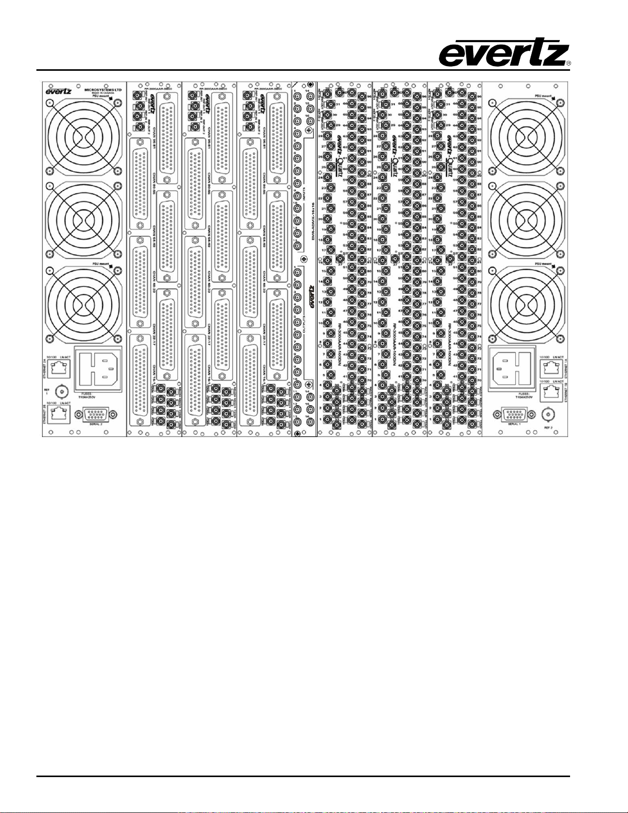
2-1 shows the rear of the 3000FR frame and 3000FC connections.
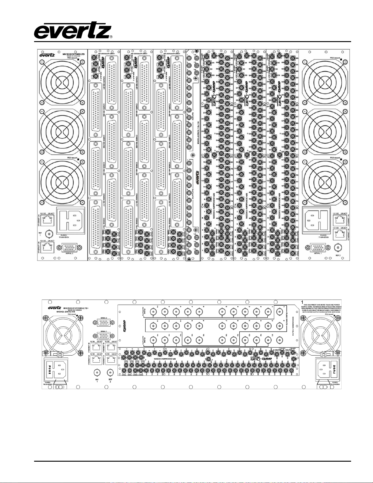
2-2 and Figure 2-3 show the
Note: Rear panels are placed horizontally in the EMX3-FR frame and as a result, some
scre
Balanced AES, LTC and Data Port modules.
COMPONENT OVERVIEW Revision 1.8 Page 3
Page 18
EMR User's Guide
High Density Modular Audio Router (AES, Analog, MADI, TimeCode, Data)
Figure
2-1: 3000FR Rear View
Page 4 Revision 1.8 COMPONENT OVERVIEW
Page 19
EMR User's Guide
High Density Modular Audio Router (AES, Analog, MADI, TimeCode, Data)
AESB AESU
Figure 2-2: EMX6-FR Rear View
Figure 2-3: EMX3-FR Rear View
COMPONENT OVERVIEW Revision 1.8 Page 5
Page 20

EMR User's Guide
High Density Modular Audio Router (AES, Analog, MADI, TimeCode, Data)
2.2. EMR I/O MODULES
The EMR system is built from a variety of input and output modules. All modules are hot-swappable and
can reside in any one of the 15 slots of the 3000FR or EMX6-FR frames or 5 slots of the EMX3-FR frame.
Available I/O modules include:
1. EMR-IP96-AESU 96 Unbalanced AES inputs with TDM outputs
2. EMR-IP96-AESB 96 Balanced AES inputs with TDM outputs
3. EMR-IP48-AESU 48 Unbalanced AES inputs with TDM outputs
4. EMR-IP48-AESB 48 Balanced AES inputs with TDM outputs
5. EMR-IP48-AA 48 Analog stereo inputs with TDM outputs
6. EMR-OP96-AESU 96 Unbalanced AES outputs with TDM inputs
7. EMR-OP96-AESB 96 Balanced AES outputs with TDM inputs
8. EMR-OP48-AESU 48 Unbalanced AES outputs with TDM inputs
9. EMR-OP48-AESB 48 Balanced AES outputs with TDM inputs
10. EMR-OP48-AA 48 Analog stereo outputs with TDM inputs
11. EMR-ADMX-16X16A 16 TDM inputs and 16 TDM outputs
12. EMR-ADMX-16X16 16 TDM inputs and 16 TDM outputs
13. EMR-ADMX-48X48 48 TDM inputs and 48 TDM outputs
14. EMR-IP16-MADI 16 MADI inputs with TDM outputs
15. EMR-OP16-MADI 16 MADI outputs with TDM inputs
16. 3000ADMX-16X16 16 TDM inputs and 16 TDM outputs
17. 3000MADI16-TDM4 *OBSOLETE* 16 MADI inputs with TDM outputs
18. 3000TDM4-MADI16 *OBSOLETE* 16 MADI outputs with TDM inputs
19. EMR-IP96-LTC 96 LTC inputs with TDM outputs
20. EMR-IP48-LTC 48 LTC inputs with TDM outputs
21. EMR-OP96-LTC 96 LTC outputs with TDM inputs
22. EMR-OP48-LTC 48 LTC outputs with TDM Inputs
23. EMR-PR48 48 data ports with 4 TDM inputs and 4 TDM outputs
24. EMR-PR48-A 48 data ports with 4 TDM inputs and 4 TDM outputs
25. EMR-IO8-MADI 8 MADI inputs with TDM outputs and 8 MADI outputs with TDM inputs
Detailed module descriptions, module rear plate drawings, and specifications are provided in the following
sections.
2.2.1. EMR-IP96 (48)-AESU (B) AES Audio Input Module
The E MR-IP96 (48)-AESU (B) is an AES audio input card for the EMR. It supports 96 or 48 discrete AES
inputs (192 or 96 mono channels). Additionally, there is one MADI input which can carry up to 64
channels of digital audio, giving a total of 256 or 160 mono channels of audio.
The latest firmware version takes the 256 channels of audio and multiplexes them onto 2 TDM streams.
One stream is the main and the other is the redundant. Either TDM stream can be used as the primary
since they are identical.
There is also one video monitoring output which can be used to visualize the audio levels using level
meters for each channel. This monitoring output is a 720p/59.94 signal that provides a visual confirmation
of audio presence and levels. On the unbalanced AES version, the availability of this output depends on
the configuration of the link module as described in Table
2-1.
Page 6 Revision 1.8 COMPONENT OVERVIEW
Page 21
EMR User's Guide
High Density Modular Audio Router (AES, Analog, MADI, TimeCode, Data)
2.2.1.1. Unbalanced AES Input Rear Panel
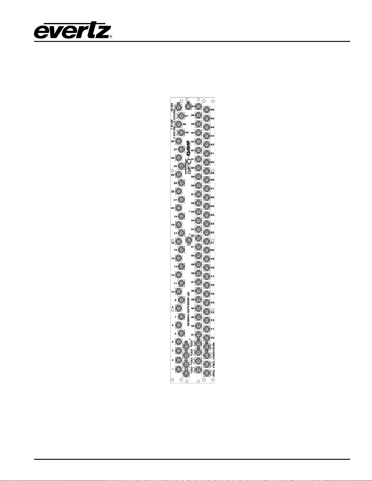
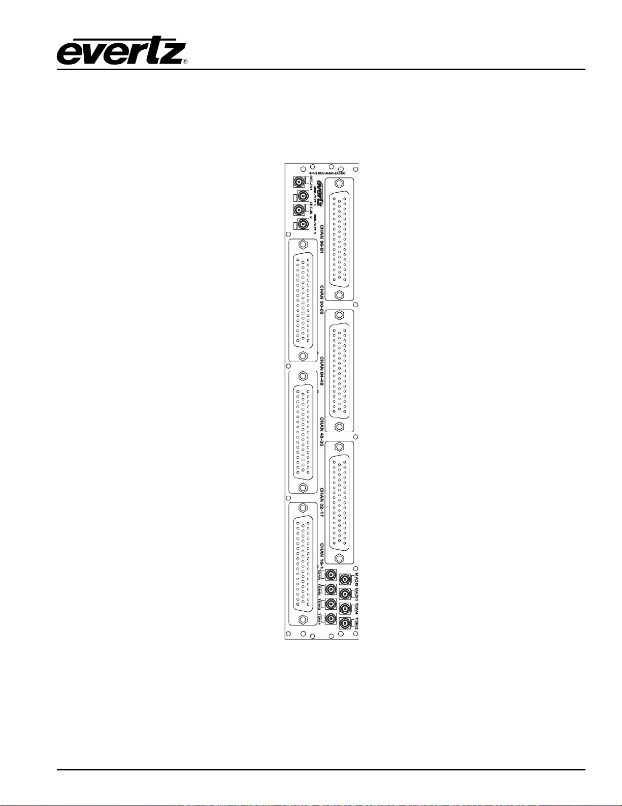
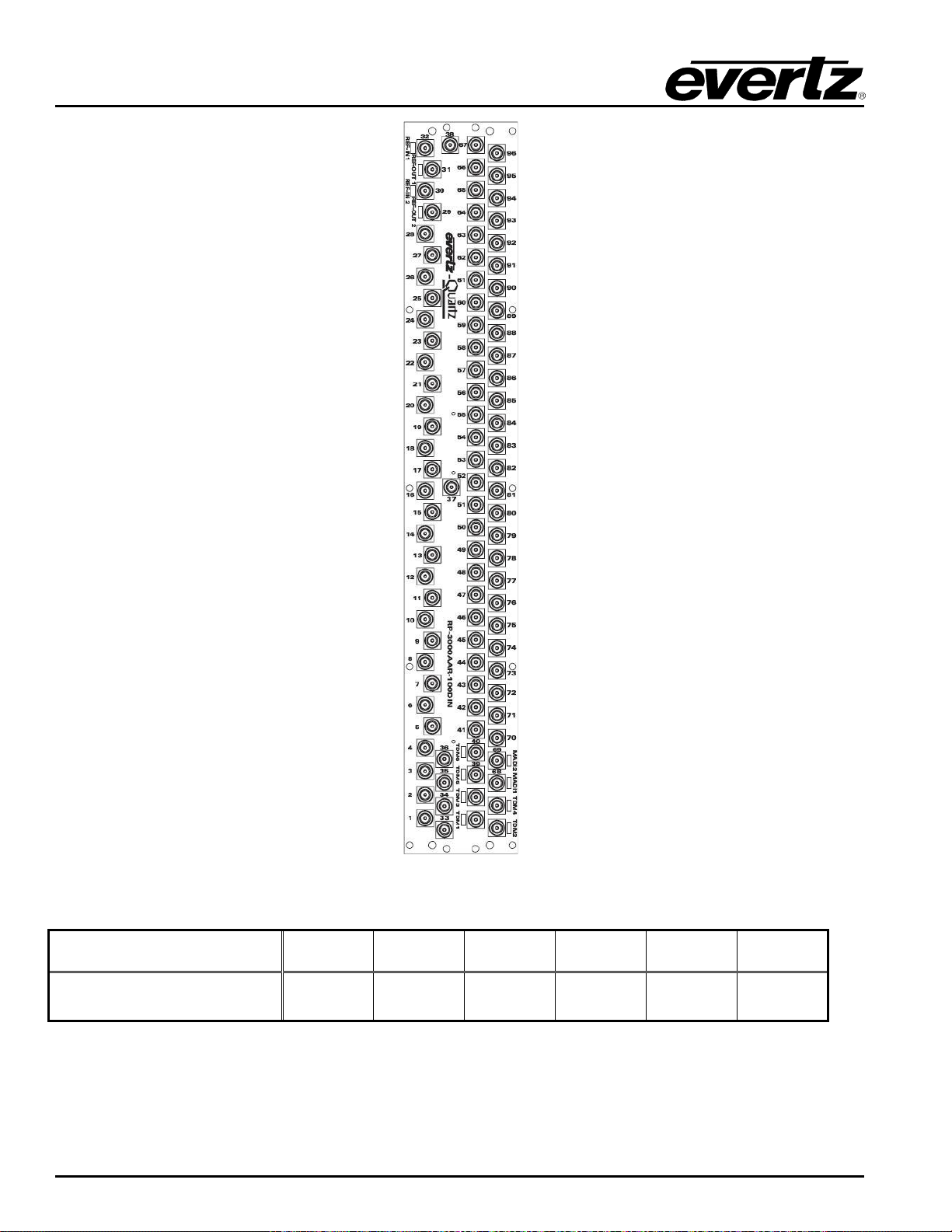
The AESU version of the rear panel occupies 2 slots in a frame and has unbalanced AES inputs with DIN
1.0/2.3 connectors as shown in Figure
IP96-AESU but only the first 48 AES inputs are enabled.
2-4. The E MR-IP48-AESU uses the same rear plate as the EMR-
Figure
2-4: EMR-I P96 (48)-AESU Rear Plate
Of the 100 DIN 1.0/2.3 connectors, inputs 1-96 are dedicated AES inputs. The connectors TDM1 and
TDM2 are dedicated TDM outputs.
Connectors TDM3, TDM4, TDM5/39, TDM6/40, MADI1/68 and MADI2/69 have different functions
depending on which link module is installed. The link module is a small printed circuit board (PCB)
COMPONENT OVERVIEW Revision 1.8 Page 7
Page 22

EMR User's Guide
Video
OUT
MADI
IN
AES IN
39
High Density Modular Audio Router (AES, Analog, MADI, TimeCode, Data)
located near the back of the main module. Depending on which module is installed, the connectors have
different functions. Table
LINK MODULE TDM3 TDM4 TDM5/39 TDM6/40 MADI1/68 MADI2/69
2-1 shows the different I/O configurations available.
(A-EMR-AES-UNBALT3)
AES IN 40 AES IN 68 AES IN 69
Table 2-1: Link Module Options for EMR-IP96 (48)-AESU
Page 8 Revision 1.8 COMPONENT OVERVIEW
Page 23
EMR User's Guide
High Density Modular Audio Router (AES, Analog, MADI, TimeCode, Data)
2.2.1.2. Balanced AES Input Rear Panel
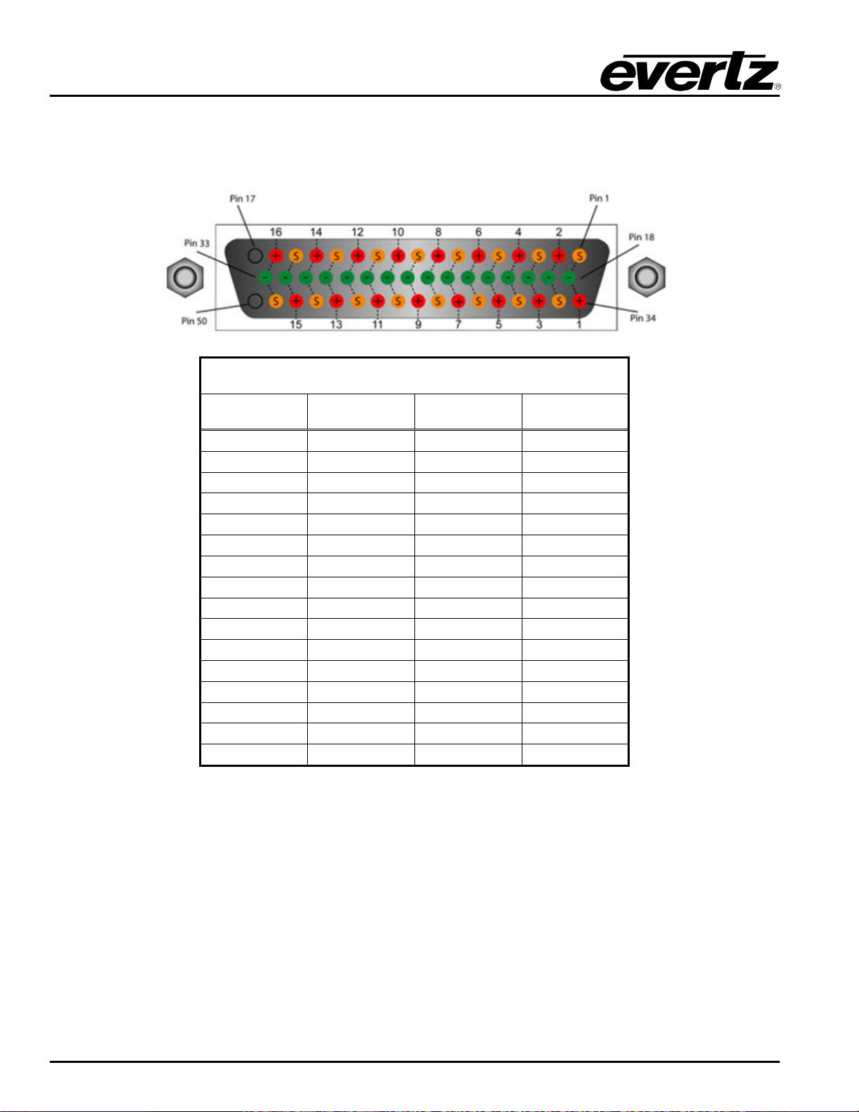
The AESB version of the rear panel occupies 2 slots in a frame and has balanced AES inputs using a rear
plate that has 50-pin D-Sub female connectors as shown in Figure
same rear plate as the EMR-IP96-AESB but only the first three 50-pin D-Sub connectors are enabled.
2-5. The EMR-IP48-AESB uses the
Figure
2-5: EMR-I P96 (48)-AESB Rear Plate
The balanced AES inputs are interfaced by 50-pin D-Sub female connectors. Each connector supports 16
mono channels of balanced AES. The pinout for each connector is shown in Table
2-2. All other I/O
signals use DIN 1.0/2.3 connectors. The control of the monitoring ports is not currently supported.
TDM1 and TDM2 are TDM outputs, while TDM 3 is a video output. The connector MADI2 is a MADI input.
COMPONENT OVERVIEW Revision 1.8 Page 9
Page 24
EMR User's Guide
High Density Modular Audio Router (AES, Analog, MADI, TimeCode, Data)
2.2.1.3. Balanced AES Input D50 Connector – Pin Out
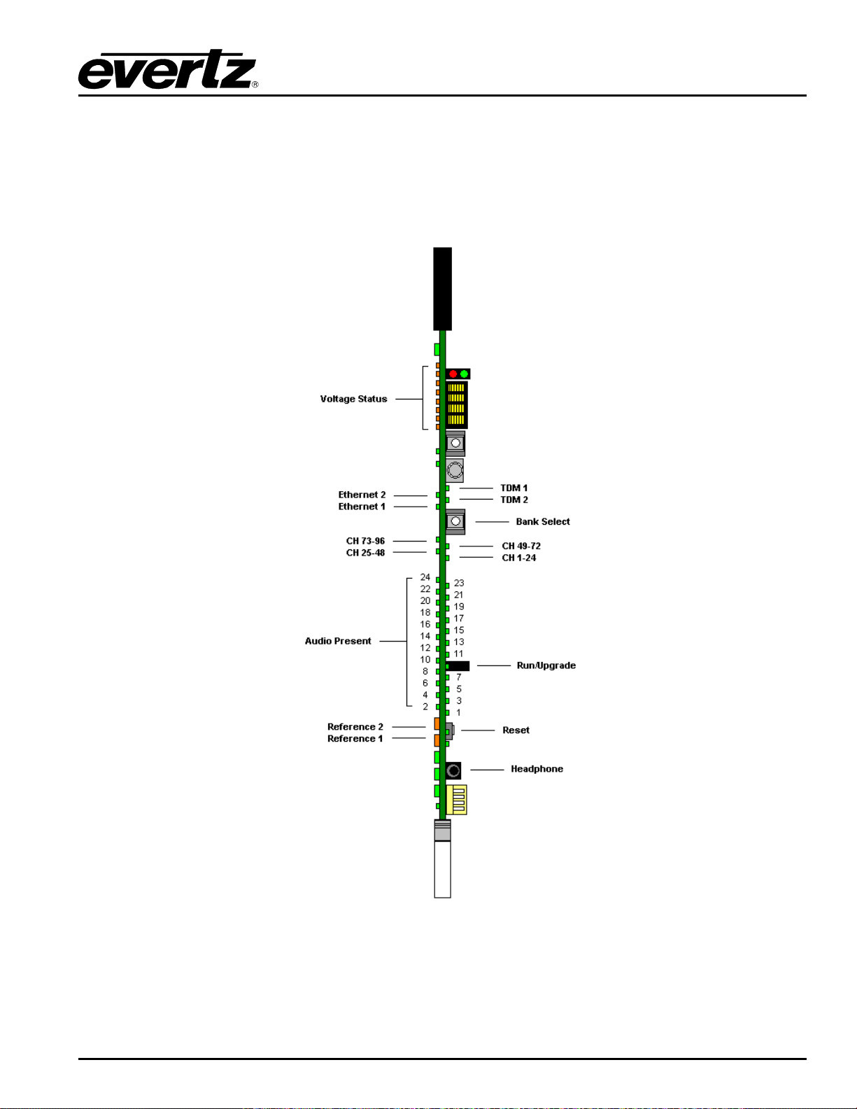
The E MR-IP96 (48)-AESB audio cards use female 50-pin D-Sub connectors, with each connector carrying
16 signals. Table
2-2 outlines the pinot for the connectors.
D50 Audio Pin-Out Table
Signal +ve Pin -ve Pin Screen
1 34 18 1
2 2 19 35
3 36 20 3
4 4 21 37
5 38 22 5
6 6 23 39
7 40 24 7
8 8 25 41
9 42 26 9
10 10 27 43
11 44 28 11
12 12 29 45
13 46 30 13
14 14 31 47
15 48 32 15
16 16 33 49
Table 2-2: Balanced AES Audio Input Pin-Out
Page 10 Revision 1.8 COMPONENT OVERVIEW
Page 25
EMR User's Guide
High Density Modular Audio Router (AES, Analog, MADI, TimeCode, Data)
2.2.1.4. Front Card Edge Controls and LEDs
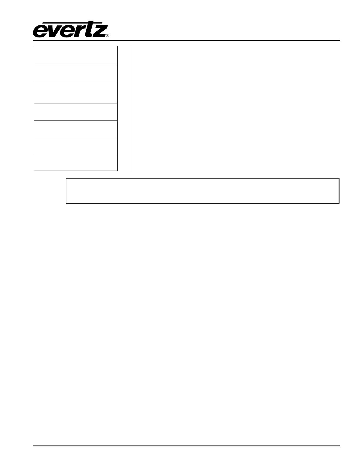
The E MR-IP96 (48)-AESU (B) front card edge has some key controls and indicators that can help in the
installation and debugging processes. Figure
expected behavior of each component. If the status indicators do not behave as described it can be a
sign of installation or configuration issues.
2-6 and Table 2-3 show the card edge and describe the
Figure
2-6: EMR-I P96 (48)-AESU (B) Fr ont Card Edge
COMPONENT OVERVIEW Revision 1.8 Page 11
Page 26

EMR User's Guide
High Density Modular Audio Router (AES, Analog, MADI, TimeCode, Data)
Component Description
Voltage Status LEDs
Ethernet 1 LED
Ethernet 2 LED
Bank Select Push
Button
CH 1-24 LED
CH 25-48 LED
CH 49-72 LED
CH 73-96 LED
Audio Present LEDs
Run/Upgrade Jumper
Reference 1 LED
This set of LEDs are amber in color and should always be ON
This LED is green in color and flashes when there is activity on
Ethernet port 1
This LED is green in color and flashes when there is activity on
Ethernet port 2
Selects the bank of inputs that are being monitored by the Audio
Present LEDs
This LED is green in color and indicates that inputs 1 to 24 are
currently being monitored by the Audio Present LEDs
This LED is green in color and indicates that inputs 25 to 48 are
currently being monitored by the Audio Present LEDs
This LED is green in color and indicates that inputs 49 to 72 are
currently being monitored by the Audio Present LEDs
This LED is green in color and indicates that inputs 73 to 96 are
currently being monitored by the Audio Present LEDs
This set of LEDs are green in color and indicate the presence of
audio on each respective input
This jumper is used to place the module in upgrade mode when
upgrading the firmware
This LED is amber in color and indicates the presence of a valid
reference on input 1. It will flash rapidly if reference is present and
slowly if it is the primary reference
This LED is amber in color and indicates the presence of a valid
Reference 2 LED
Reset Button
Headphone Jack
reference on input 2. It will flash rapidly if reference is present and
slowly if it is the primary reference
This button resets the module
This jack allows a user to monitor audio signals from a pair of
headphones
Table 2-3: Description of EMR-IP96 (48)-AESU (B) Card Edge
2.2.1.5. Configuration and Monitoring Menu
EMR-IP96 (48)-AESU (B) contains configuration and monitoring menu that allows the user to change
some internal settings of the device and also to monitor various components on the card.
The configuration and monitoring menu can be accessed using either Telnet session or serial connection.
Once gained access to the main menu, use the numbers beside the items to set the value. Follow the on
screen instructions to set the value of the parameter, save and exit the configuration.
Page 12 Revision 1.8 COMPONENT OVERVIEW
Page 27
EMR User's Guide
View of audio channel status, frame reference, board and TDM
Configuration of Headphone port, Tone Gen and Audio pair control
Audio Monitor Cast
Service Config
High Density Modular Audio Router (AES, Analog, MADI, TimeCode, Data)
Network Configuration Configuration of Network 1 and 2
SNMP Configuration Configuration of Simple Network Management Protocol settings.
Audio Configuration
Set TDM Version Configuration of TDM versions (TDM v2 is for future use)
Trace - Engineering Only Configured under the supervision of Evertz technical support staff only
Engineering Debug Utility Accessed by Evertz technical support staff only
Note: The default TDM version has to be set to V1; TDM V2 is for future use.
2.2.2. EMR-OP96 (48)-AESU (B) AES Audio Output Module
The E MR-OP96 (48)-AESU (B) is an AES audio output card for the EMR. It supports 96 or 48 discrete
AES outputs (192 or 96 mono channels). Additionally, there is one MADI output which can carry up to 64
channels of digital audio, giving a total of 256 or 160 mono channels of audio.
The latest firmware version de-multiplexes the 256 channels of audio from 1 of 2 TDM input streams. One
stream is the primary and the other is the redundant. Either TDM stream can be used as the primary
since they are identical. The system can be configured to default to the redundant stream if the primary is
missing.
There is also one video monitoring output which can be used to visualize the audio levels using level
meters for each channel. This monitoring output is a 720p/59.94 signal that provides a visual confirmation
of audio presence and levels. On the unbalanced AES version, the availability of this output depends on
the configuration of the link module as described in Table
AESU.
information.
Configuration of Cast service
2-4: Link Module Options for EMR-OP96 (48)-
2.2.2.1. Unbalanced AES Output Rear Panel
The AESU version of the rear panel occupies 2 slots in a frame and has unbalanced AES outputs with
DIN 1.0/2.3 connectors as shown in Figure
EMR-OP96-AESU but only the first 48 AES outputs are enabled.
Beside each input labeled TDM there is a small LED adjacent to the connector that will light up solid green
if it sees a valid MADI signal or valid T DM signal. The LED will remain solid if a valid T DM is the primary
TDM and it will flash if a valid TDM is detected but not currently used.
COMPONENT OVERVIEW Revision 1.8 Page 13
2-7. T he EMR-OP48-AESU uses the same rear plate as the
Page 28
EMR User's Guide
High Density Modular Audio Router (AES, Analog, MADI, TimeCode, Data)
Figure
2-7: EMR-O P96 (48)-AESU Rear Plate
Link Module TDM3 TDM4 TDM5/39 TDM6/40 MADI1/68 MADI2/69
(A-EMR-AES-UNBALT2)
Table
MADI
OUT
2-4: Link Module Options for EMR-OP96 (48)-AESU
Video
OUT
AES OUT
39
AES OUT
40
AES OUT
68
AES OUT
69
Page 14 Revision 1.8 COMPONENT OVERVIEW
Page 29
EMR User's Guide
High Density Modular Audio Router (AES, Analog, MADI, TimeCode, Data)
2.2.2.2. Balanced AES Output Rear Panel
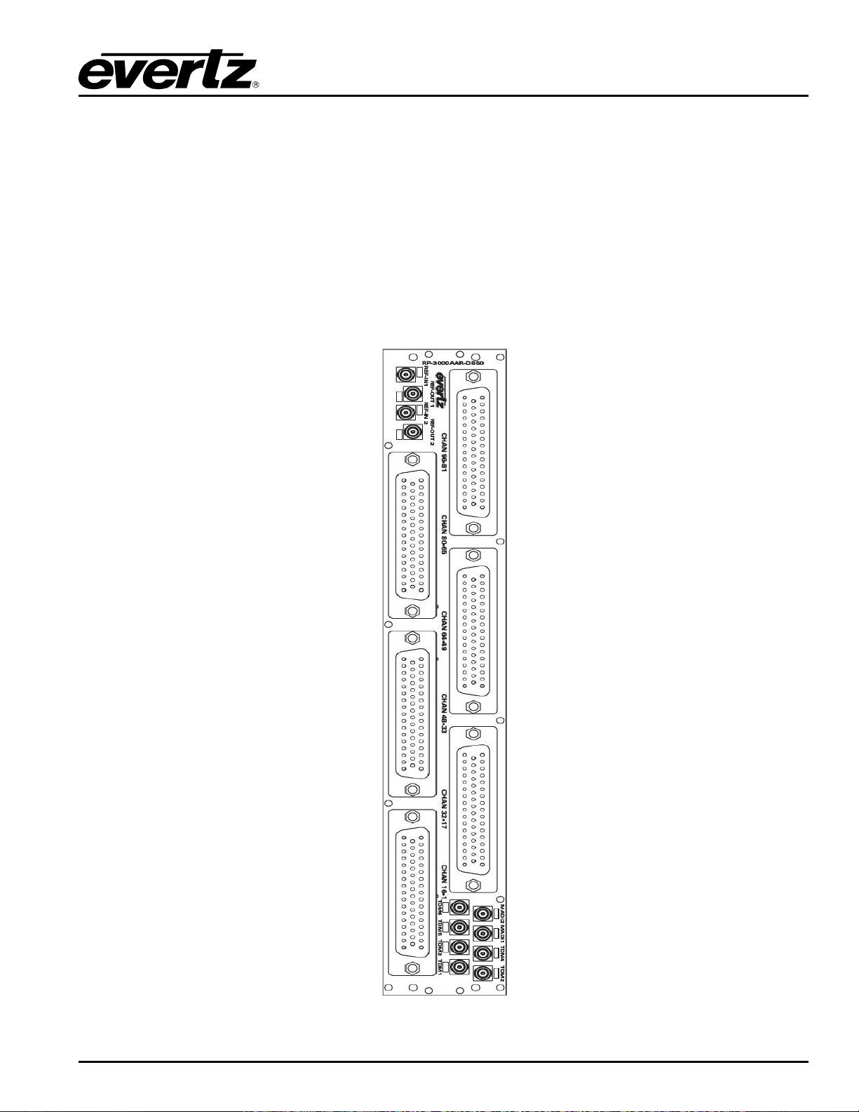
The AESB version of the rear panel occupies 2 slots in a frame and has balanced AES outputs using a
rear plate that has 50-pin D-Sub female connectors as shown in Figure
the same rear plate as the EMR-OP96-AESB but only the first three 50-pin D-Sub connectors are
enabled. The control of the monitoring ports is not currently supported.
Connectors TDM1-TDM5 are TDM inputs and the connector MADI1 is a MADI output, and the connector
TDM6 is a video output.
Beside each input labeled TDM there is a small LED adjacent to the connector that will light up solid green
if it sees a valid MADI signal or valid TDM signal. The LED will remain solid if a valid TDM is the primary
TDM and it will flash if a valid TDM is detected but not currently used.
2-8. T he E MR-OP48-AESB uses
Figure
2-8: EMR-O P96 (48)-AESB Rear Plate
COMPONENT OVERVIEW Revision 1.8 Page 15
Page 30
EMR User's Guide
High Density Modular Audio Router (AES, Analog, MADI, TimeCode, Data)
2.2.2.3. Balanced AES Output D50 Connector – Pin Out
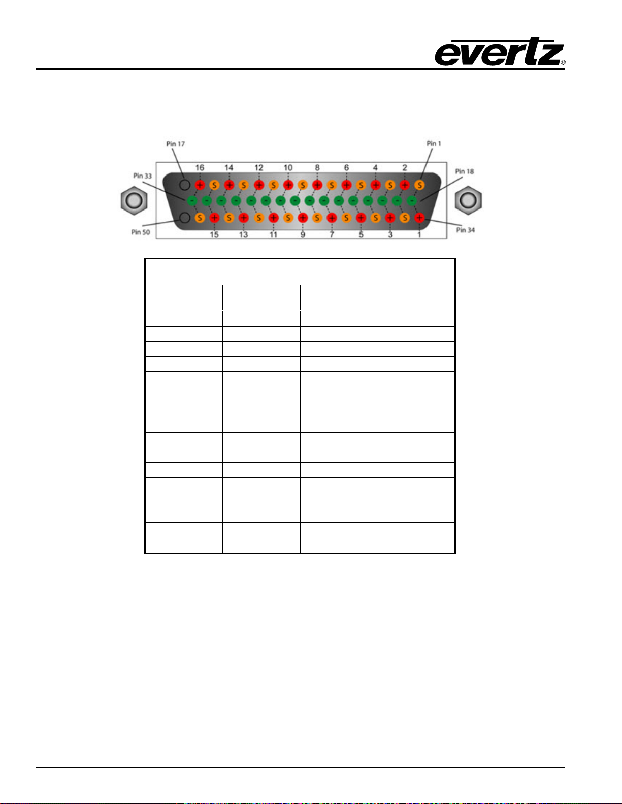
The EMR-OP96 (48)-AESB audio cards use female 50-pin D-Sub connectors, with each connector
carrying 16 signals. Table
2-5 outlines the pinout for the connectors.
D50 Audio Pin-Out Table
Signal +ve Pin -ve Pin Screen
1 34 18 1
2 2 19 35
3 36 20 3
4 4 21 37
5 38 22 5
6 6 23 39
7 40 24 7
8 8 25 41
9 42 26 9
10 10 27 43
11 44 28 11
12 12 29 45
13 46 30 13
14 14 31 47
15 48 32 15
16 16 33 49
Table 2-5: Balanced AES Audio Output Pin-Out
Page 16 Revision 1.8 COMPONENT OVERVIEW
Page 31
EMR User's Guide
High Density Modular Audio Router (AES, Analog, MADI, TimeCode, Data)
2.2.2.4. Front Card Edge Controls and LEDs
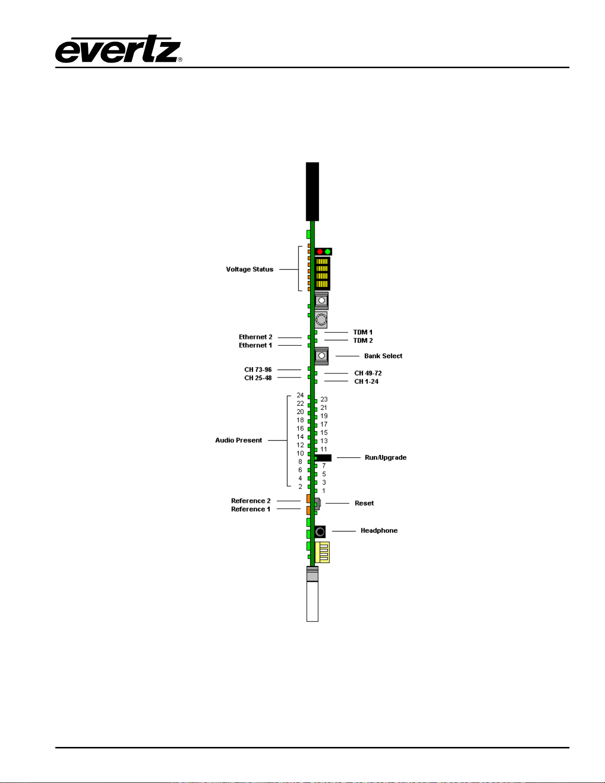
The E MR-OP96 (48)-AESU (B) front card edge has some key controls and indicators that can help in the
installation and debugging processes. Figure
expected behavior of each component. If the status indicators do not behave as described it can be a
sign of installation or configuration issues.
2-9 and Table 2-6 show the card edge and describe the
Figure
2-9: EMR-O P96 (48)-AESU (B) Fr ont Card Edge
COMPONENT OVERVIEW Revision 1.8 Page 17
Page 32

EMR User's Guide
This jack allows a user to monitor audio signals from a pair of
headphones
High Density Modular Audio Router (AES, Analog, MADI, TimeCode, Data)
Component Description
Voltage Status LEDs
Ethernet 1 LED
Ethernet 2 LED
TDM 1
TDM 2
Bank Select Push
Button
CH 1-24 LED
CH 25-48 LED
CH 49-72 LED
CH 73-96 LED
This set of LEDs are amber in color and should always be ON
This LED is green in color and flashes when there is activity on
Ethernet port 1
This LED is green in color and flashes when there is activity on
Ethernet port 2
This LED is green in color and flashes when a valid TDM signal is
detected on TDM input 1 and is solid when it is the primary TDM
This LED is green in color and flashes when a valid TDM signal is
detected on TDM input 2 and is solid when it is the primary TDM
Selects the bank of inputs that are being monitored by the Audio
Present LEDs
This LED is green in color and indicates that inputs 1 to 24 are
currently being monitored by the Audio Present LEDs
This LED is green in color and indicates that inputs 25 to 48 are
currently being monitored by the Audio Present LEDs
This LED is green in color and indicates that inputs 49 to 72 are
currently being monitored by the Audio Present LEDs
This LED is green in color and indicates that inputs 73 to 96 are
currently being monitored by the Audio Present LEDs
Audio Present LEDs
Run/Upgrade Jumper
Reference 1 LED
Reference 2 LED
Reset Button
Headphone Jack
This set of LEDs are green in color and indicate the presence of
audio on each respective input
This jumper is used to place the module in upgrade mode when
upgrading the firmware
This LED is amber in color and indicates the presence of a valid
reference on input 1. It will flash rapidly if reference is present and
slowly if it is the primary reference
This LED is amber in color and indicates the presence of a valid
reference on input 2. It will flash rapidly if reference is present and
slowly if it is the primary reference
This button resets the module
Table 2-6: Description of EMR-OP96 (48)-AESU ( B) Card Edge
2.2.2.5. Configuration and Monitoring Menu
EMR-OP96 (48)-AESU (B) contains configuration and monitoring menu that allows the user to change
some internal settings of the device and also to monitor various components on the card.
The configuration and monitoring menu can be accessed using either Telnet session or serial connection.
Once gained access to the main menu, use the numbers beside the items to set the value. Follow the on
screen instructions to set the value of the parameter, save and exit the configuration.
Page 18 Revision 1.8 COMPONENT OVERVIEW
Page 33
EMR User's Guide
View of audio channel status, frame reference, board and TDM
Configuring Headphone port, Tone Gen and Audio pair control
Service Config
High Density Modular Audio Router (AES, Analog, MADI, TimeCode, Data)
Network Configuration Configuration of Network 1 and 2
SNMP Configuration Configuration of Simple Network Management Protocol.
Audio Configuration
Set TDM Version Configuration of TDM versions (TDM v2 is for future use)
Audio Monitor Cast
Trace - Engineering Only Configured under the supervision of Evertz technical support staff only
Engineering Debug Utility Accessed by Evertz technical support staff only
Note: The default TDM version has to be set to V1; TDM V2 is for future use.
information.
Configuration of Cast service
COMPONENT OVERVIEW Revision 1.8 Page 19
Page 34
EMR User's Guide
High Density Modular Audio Router (AES, Analog, MADI, TimeCode, Data)
Figure
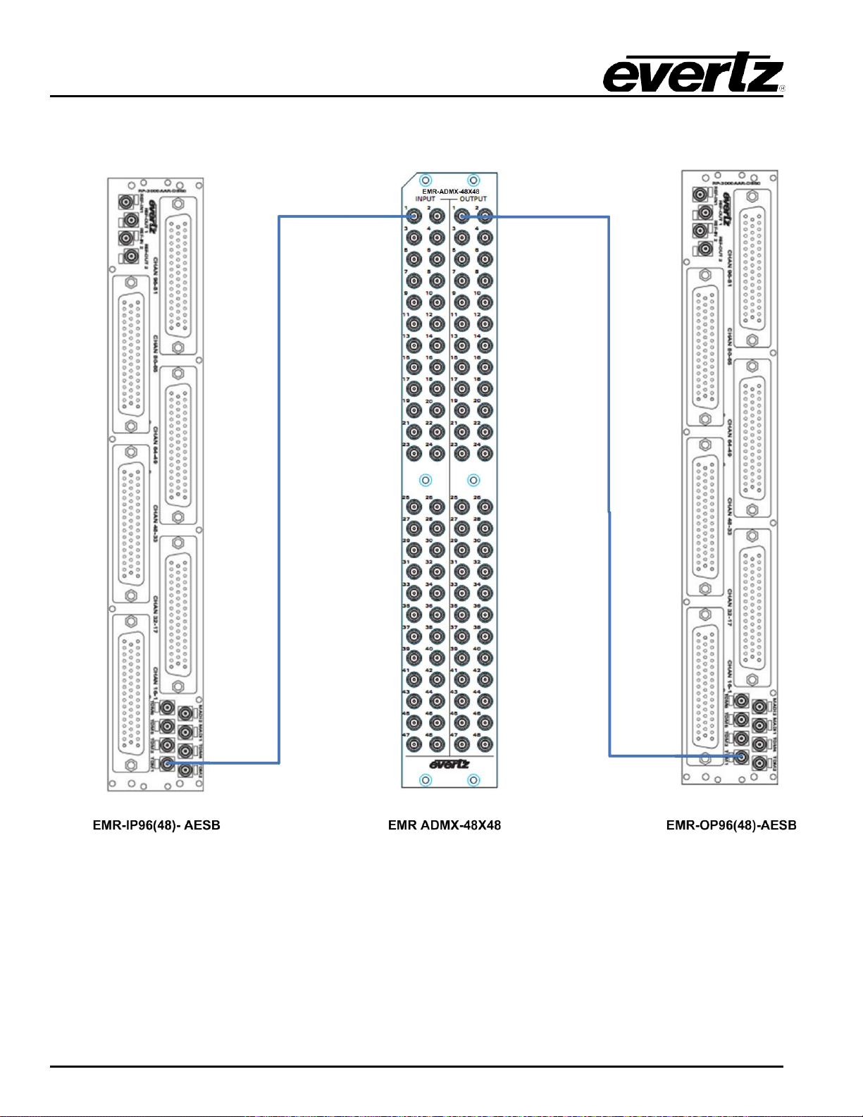
2-10: Basic EMR AESB Setup with ADMX-48x48
Page 20 Revision 1.8 COMPONENT OVERVIEW
Page 35
EMR User's Guide
High Density Modular Audio Router (AES, Analog, MADI, TimeCode, Data)
Figure
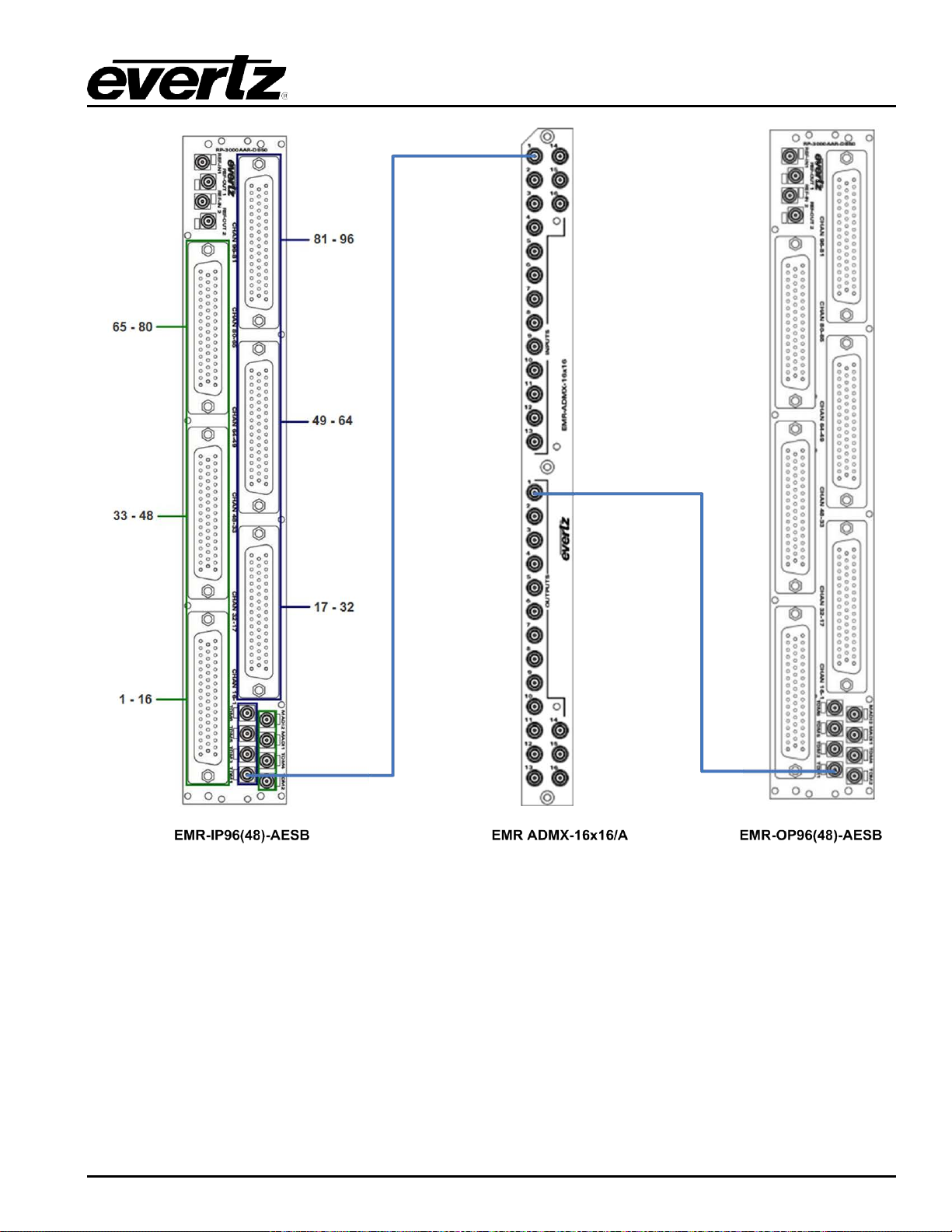
2-11: Basic EMR AESB Setup with ADMX-16X16/A
COMPONENT OVERVIEW Revision 1.8 Page 21
Page 36
EMR User's Guide
High Density Modular Audio Router (AES, Analog, MADI, TimeCode, Data)
Figure
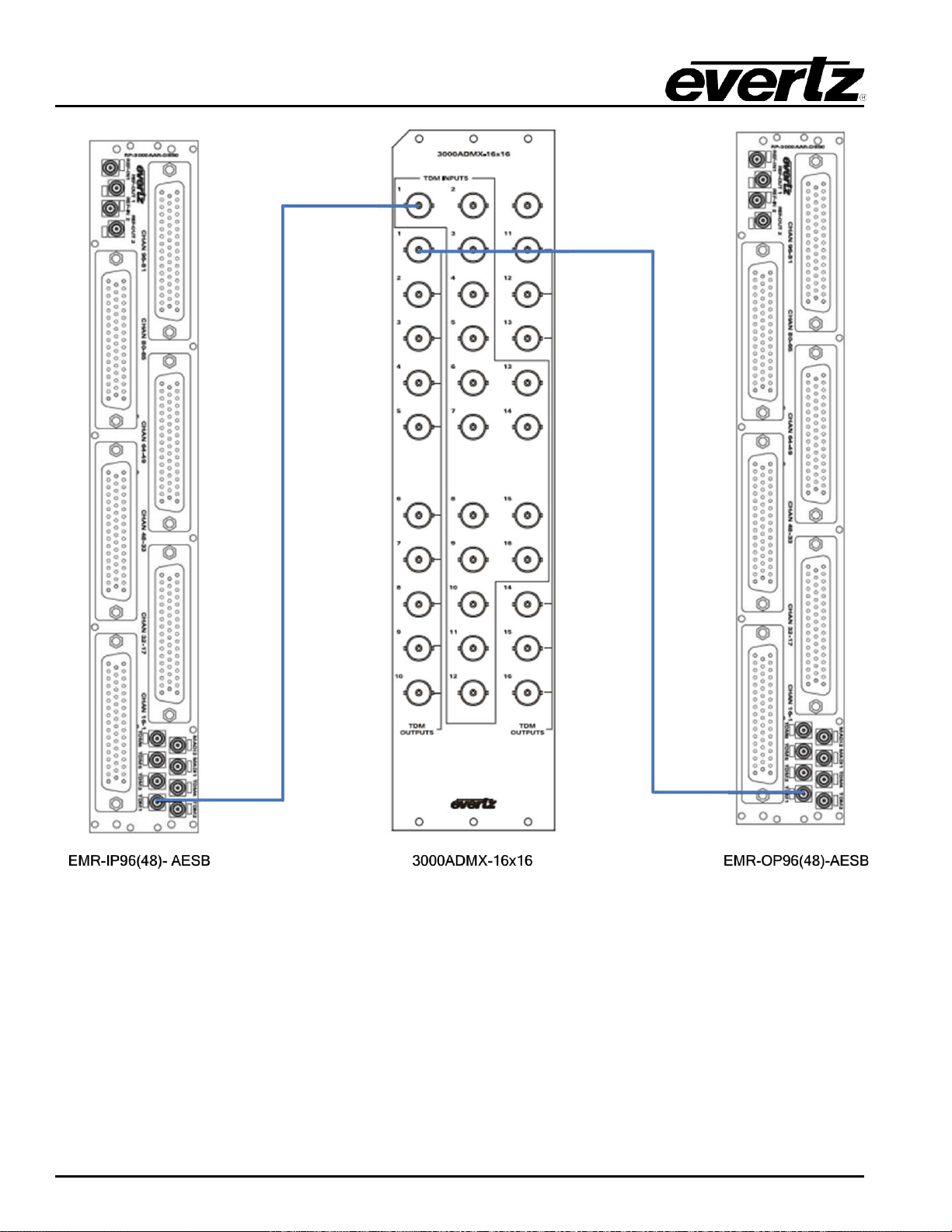
2-12: Basic EMR AESB Setup with ADMX
Page 22 Revision 1.8 COMPONENT OVERVIEW
Page 37
EMR User's Guide
Please Note: It is necessary to set the IP address on both half modules. Also, the user
High Density Modular Audio Router (AES, Analog, MADI, TimeCode, Data)
2.2.3. EMR-IP48-AA Analog Audio Input Module
The E MR-IP48-AA is an analog audio input card for the EMR. It supports 48 stereo analog pairs (96 mono
channels). Additionally, there is one MADI input, which can carry up to 64 additional channels of audio
giving a total of 160 channels of audio.
The EMR-IP48-AA consists of two identical half modules to reduce the failure block of the analog
component. The latest version of firmware takes the 48 channels of audio from each half module and the
MADI input, and multiplexes them onto 2 TDM streams. One stream is the main and the other is the
redundant. Either TDM stream can be used as the primary since they are identical.
There is also one video monitoring output which can be used to visualize the audio levels using level
meters for each channel. This monitoring output is a 720p/59.94 signal that provides a visual confirmation
of audio presence and levels.
The EMR-IP48-AA rear panel occupies 2 slots in a frame and has 50-pin D-Sub female connectors as
shown in Figure
connector supports 8 stereo pairs of analog audio. The pin out for each connector is shown in Table
All other I/O signals use DIN 1.0/2.3 connectors. The control of the monitoring ports is not currently
supported.
The TDM 1 and TDM 5 connectors are the main and redundant TDM outputs respectively. TDM 3 is the
video output and the connector labeled MADI2 is a MADI Input.
2-13. The analog inputs are interfaced by the six 50-pin D-Sub female connectors. Each
2-7.
must load code on both half modules. The left module’s IP address will be used for
Winsetup & VLPRO.
Please Note: Cards will talk to one another through a link on the rear plate.
COMPONENT OVERVIEW Revision 1.8 Page 23
Page 38
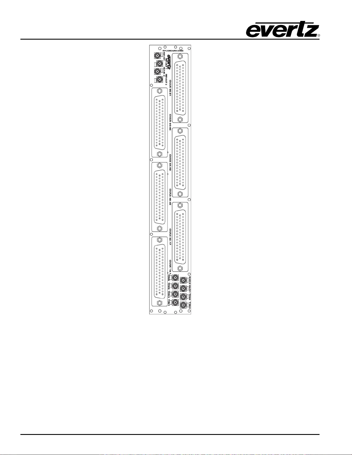
EMR User's Guide
High Density Modular Audio Router (AES, Analog, MADI, TimeCode, Data)
Figure
2-13: EMR-IP48-AA Rear Plate
Page 24 Revision 1.8 COMPONENT OVERVIEW
Page 39
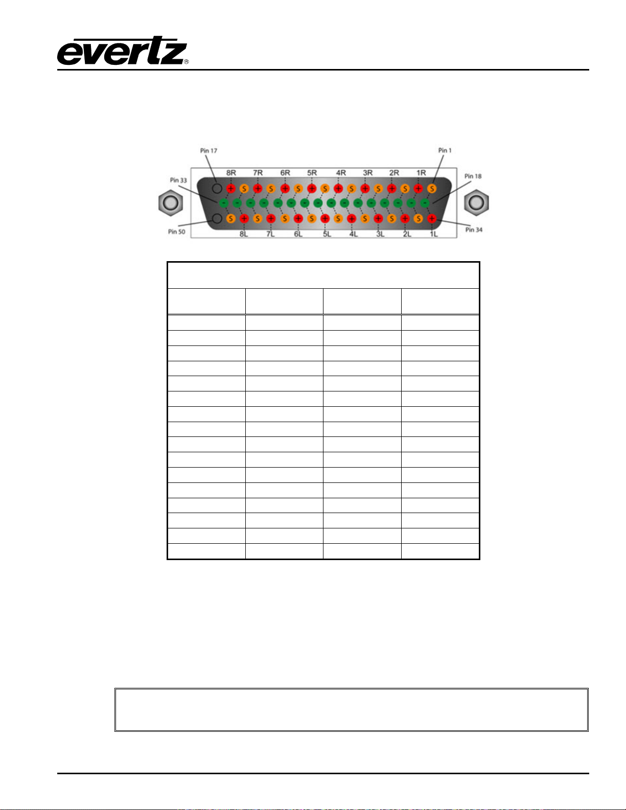
EMR User's Guide
Please Note: The left side of the input card’s IP address is used for VLPRO &
Winsetup. Both half modules should have the same code loaded on it but different IP
addresses.
High Density Modular Audio Router (AES, Analog, MADI, TimeCode, Data)
2.2.3.1. Analog Audio D50 Connector – Pin Ou t
The E MR-IP48-AA analog audio cards use female D50 connectors, with each connector carrying 8 signal
pairs. Table
2-7 outlines the pinout for the connectors.
D50 Audio Pin-Out Table
Signal + Pin - Pin Screen
1L 34 18 1
1R 2 19 35
2L 36 20 3
2R 4 21 37
3L 38 22 5
3R 6 23 39
4L 40 24 7
4R 8 25 41
5L 42 26 9
5R 10 27 43
6L 44 28 11
6R 12 29 45
7L 46 30 13
7R 14 31 47
8L 48 32 15
8R 16 33 49
Table 2-7: Analog Audio Input Pin-Out
2.2.3.2. Front Card Edge Controls and LEDs
The EMR-IP48-AA front card edge has some key controls and indicators that can help in the installation
and debugging processes. Figure
2-14 and Table 2-8 show the card edge and describe the expected
behavior of each component. If the status indicators do not behave as described it can be a sign of
installation or configuration issues.
COMPONENT OVERVIEW Revision 1.8 Page 25
Page 40
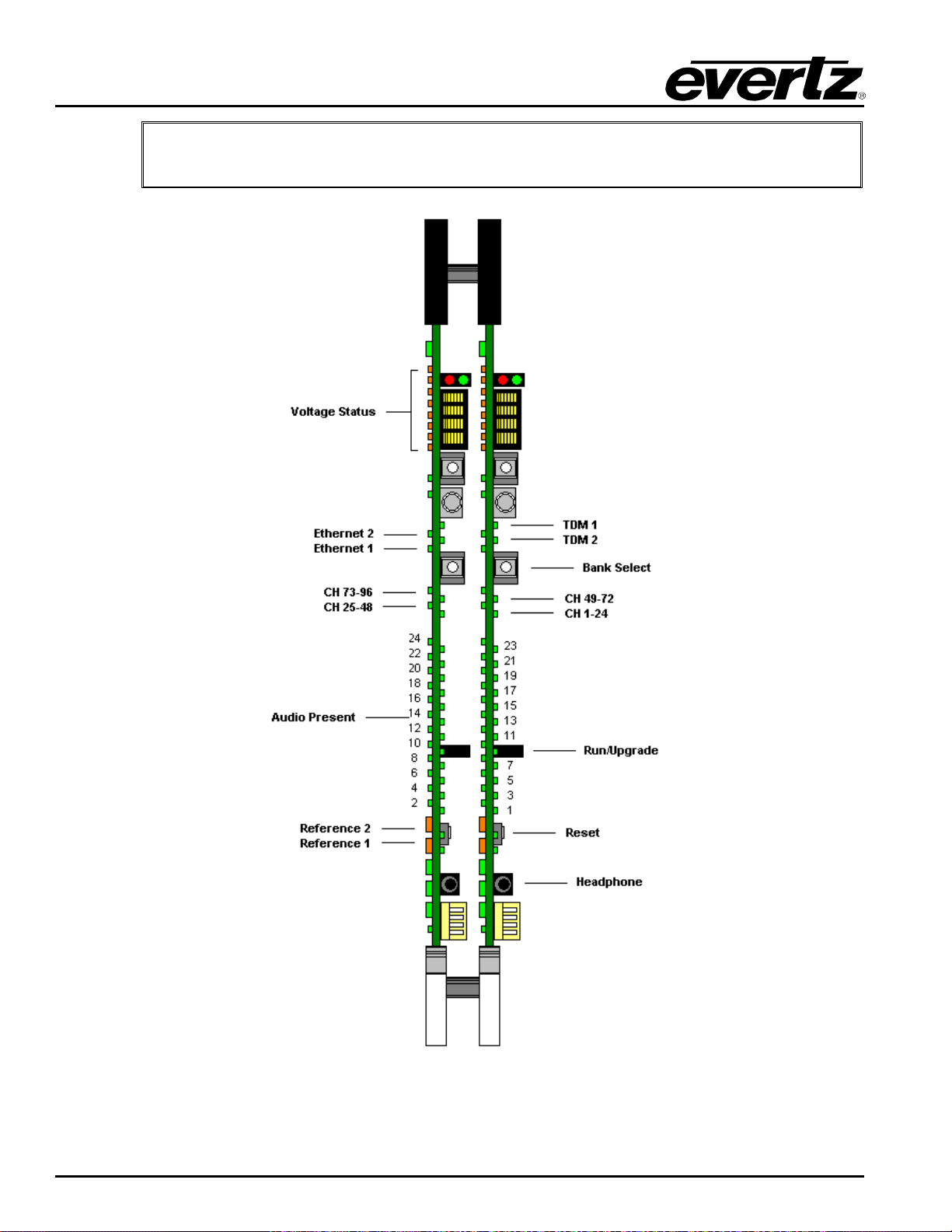
EMR User's Guide
Please Note: Analog IP card will accept an analog signal and will convert it to digital
High Density Modular Audio Router (AES, Analog, MADI, TimeCode, Data)
(TDM).
Figure
Page 26 Revision 1.8 COMPONENT OVERVIEW
2-14: EMR-IP48-AA Front Card Edge
Page 41
EMR User's Guide
High Density Modular Audio Router (AES, Analog, MADI, TimeCode, Data)
Component Description
Voltage Status LEDs
Ethernet 1 LED
Ethernet 2 LED
Bank Select Push
Button
CH 1-24 LED
CH 25-48 LED
CH 49-72 LED
CH 73-96 LED
Audio Present LEDs
Run/Upgrade Jumper
Reference 1 LED
This set of LEDs are amber in color and should always be ON
This LED is green in color and flashes when there is activity on
Ethernet port 1
This LED is green in color and flashes when there is activity on
Ethernet port 2
Selects the bank of inputs that are being monitored by the Audio
Present LEDs
This LED is green in color and indicates that inputs 1 to 24 are
currently being monitored by the Audio Present LEDs
This LED is green in color and indicates that inputs 25 to 48 are
currently being monitored by the Audio Present LEDs
This LED is green in color and indicates that inputs 49 to 72 are
currently being monitored by the Audio Present LEDs
This LED is green in color and indicates that inputs 73 to 96 are
currently being monitored by the Audio Present LEDs
This set of LEDs are green in color and indicate the presence of
audio on each respective input
This jumper is used to place the module in upgrade mode when
upgrading the firmware
This LED is amber in color and indicates the presence of a valid
reference on input 1. It will flash rapidly if reference is present and
slowly if it is the primary reference
This LED is amber in color and indicates the presence of a valid
Reference 2 LED
Reset Button
Headphone Jack
reference on input 2. It will flash rapidly if reference is present and
slowly if it is the primary reference
This button resets the module
This jack allows a user to monitor audio signals from a pair of
headphones
Table 2-8: Description of EMR-IP48-AA Card Edge
2.2.3.3. Configuration and Monitoring Menu
EMR-IP48-AA contains configuration and monitoring menu that allows the user to change some internal
settings of the device and also to monitor various components on the card.
The configuration and monitoring menu can be accessed using either Telnet session or serial connection.
Once gained access to the main menu, use the numbers beside the items to set the value. Follow the on
screen instructions to set the value of the parameter, save and exit the configuration.
COMPONENT OVERVIEW Revision 1.8 Page 27
Page 42
EMR User's Guide
View of audio channel status, frame reference and board information.
Configuration of Headphone port, Tone Gen and Audio Monitor
Configuration
Configuration of Alignment.
Service Config
High Density Modular Audio Router (AES, Analog, MADI, TimeCode, Data)
Network Configuration Configuration of Network 1 and 2
SNMP Configuration Configuration of Simple Network Management Protocol.
Audio Configuration
Audio ADC/DAC
Set TDM Version Configuration of TDM versions (TDM v2 is for future use)
Audio Monitor Cast
Trace - Engineering Only Configured under the supervision of Evertz technical support staff only
Engineering Debug Utility Accessed by Evertz technical support staff only
Note: The default TDM version has to be set to V1; TDM V2 is for future use.
2.2.4. EMR-OP48-AA Analog Audio Output Module
The E MR-OP48-AA is an analog audio output card for the EMR. It supports 48 stereo analog pairs (96
mono channels). Additionally, there is one MADI output, which can carry up to 64 additional channels of
audio giving a total of 160 channels of audio.
View of Pot CMMR, Alignment and Calibration tables.
Configuration of Cast service
Note: Analog OP card will accept a TDM signal and will convert it to analog.
The latest firmware version de-multiplexes 160 channels of audio from 1 of 2 TDM input streams. One
stream is the primary and the other is the redundant. Either TDM stream can be used as the primary
since they are identical. The system can be configured to default to the redundant stream if the primary is
missing.
There is also one video monitoring output which can be used to visualize the audio levels using level
meters for each channel. This monitoring output is a 720p/59.94 signal that provides a visual confirmation
of audio presence and levels.
The E MR-OP48-AA rear panel occupies 2 slots in a frame and has 50-pin D-Sub female connectors as
shown in Figure
Each connector supports 8 stereo pairs of analog audio. The pin out for each connector is shown in
Table
currently supported.
The connectors labeled TDM1 and TDM 2 are the main and redundant TDM inputs respectively, TDM 6 is
the video output and the connector labeled MADI1 is a MADI output.
Page 28 Revision 1.8 COMPONENT OVERVIEW
2-9. All other I/O signals use DIN 1.0/2.3 connectors. The control of the monitoring ports is not
2-15. The analog outputs are interfaced by the six 50-pin D-Sub female connectors.
Page 43
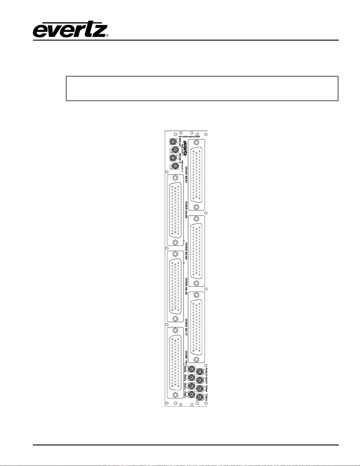
EMR User's Guide
High Density Modular Audio Router (AES, Analog, MADI, TimeCode, Data)
Beside each input labeled TDM there is a small LED adjacent to the connector that will light up solid green
if it sees a valid TDM signal. The LED will remain solid if a valid TDM is the primary TDM and it will flash if
a valid TDM is detected but not currently used.
The following signal levels are available: 24dBu, 18dBu and 15dBu.
Figure
COMPONENT OVERVIEW Revision 1.8 Page 29
2-15: EMR-OP48-AA Rear Plate
Page 44
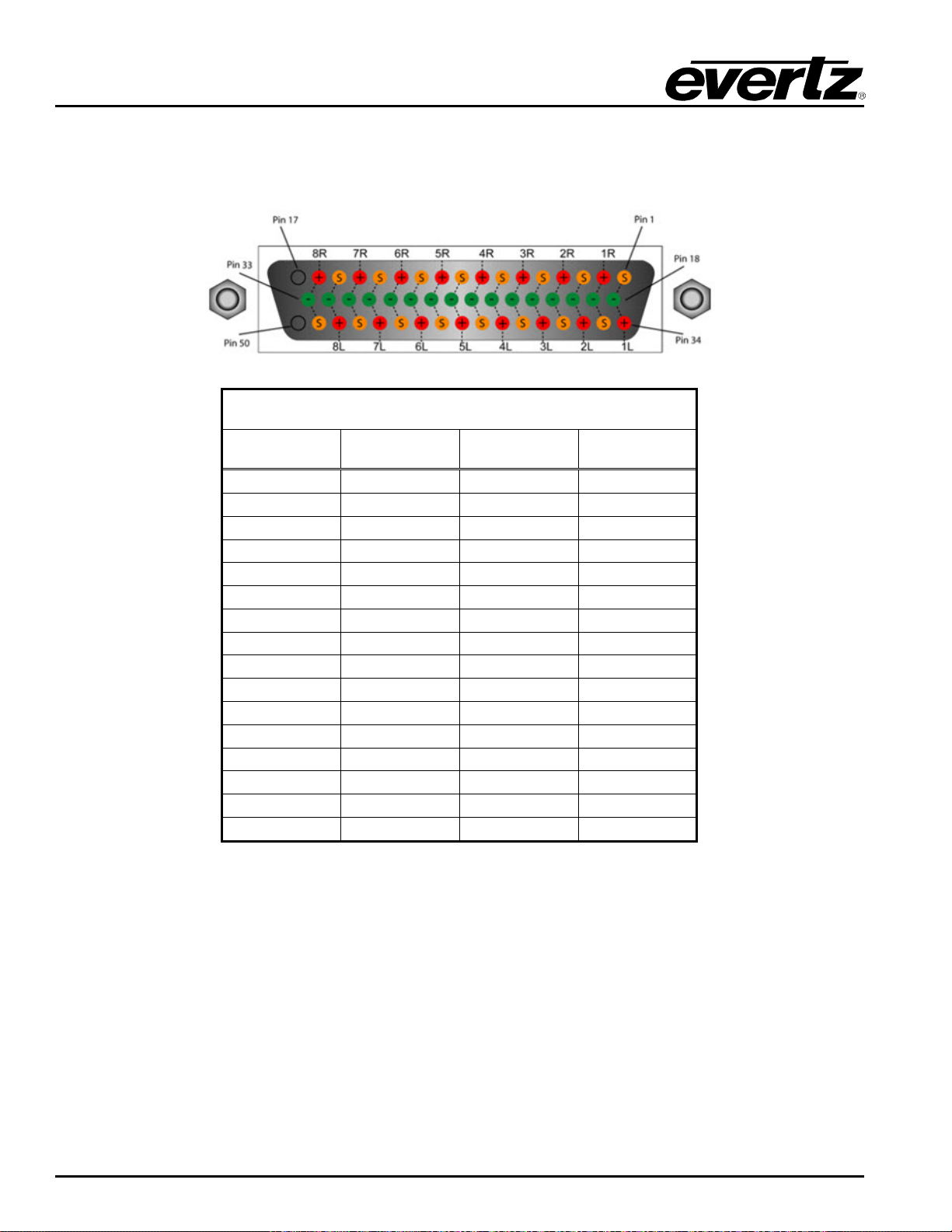
EMR User's Guide
High Density Modular Audio Router (AES, Analog, MADI, TimeCode, Data)
2.2.4.1. Analog Audio D50 Connector – Pin Ou t
The E MR-OP48-AA analog audio cards use female D50 connectors, with each connector carrying 8 signal
pairs. Table
2-9 outlines the pinout for the connectors.
D50 Audio Pin-Out Table
Signal + Pin - Pin Screen
1L 34 18 1
1R 2 19 35
2L 36 20 3
2R 4 21 37
3L 38 22 5
3R 6 23 39
4L 40 24 7
4R 8 25 41
5L 42 26 9
5R 10 27 43
6L 44 28 11
6R 12 29 45
7L 46 30 13
7R 14 31 47
8L 48 32 15
8L 16 33 49
Table 2-9: Analog Audio Output Pin-Out
Page 30 Revision 1.8 COMPONENT OVERVIEW
Page 45
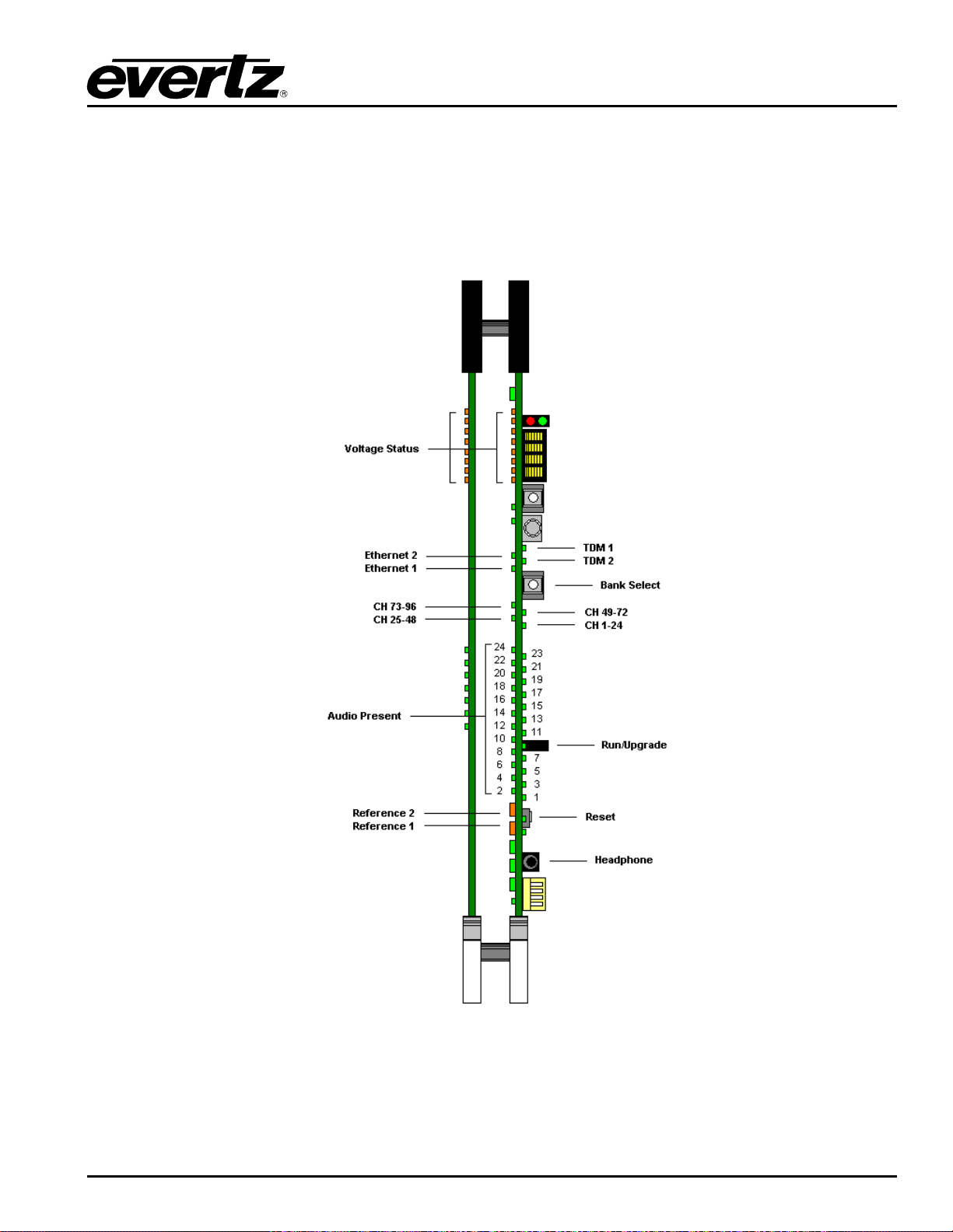
EMR User's Guide
High Density Modular Audio Router (AES, Analog, MADI, TimeCode, Data)
2.2.4.2. Front Card Edge Controls and LEDs
The E MR-OP48-AA front card edge has some key controls and indicators that can help in the installation
and debugging processes. Figure
behavior of each component. If the status indicators do not behave as described it can be a sign of
installation or configuration issues.
2-16 and Table 2-10 show the card edge and describe the expected
Figure
2-16: EMR-OP48-AA Front Card Edge
COMPONENT OVERVIEW Revision 1.8 Page 31
Page 46

EMR User's Guide
This jack allows a user to monitor audio signals from a pair of
headphones
High Density Modular Audio Router (AES, Analog, MADI, TimeCode, Data)
Component Description
Voltage Status LEDs
Ethernet 1 LED
Ethernet 2 LED
TDM 1
TDM 2
Bank Select Push
Button
CH 1-24 LED
CH 25-48 LED
CH 49-72 LED
CH 73-96 LED
This set of LEDs are amber in color and should always be ON
This LED is green in color and flashes when there is a c tivit y on
Ethernet port 1
This LED is green in color and flashes when there is activity on
Ethernet port 2
This LED is green in color and flashes when a valid TDM signal is
detected on TDM input 1 and is solid when it is the primary TDM
This LED is green in color and flashes when a valid TDM signal is
detected on TDM input 2 and is solid when it is the primary TDM
Selects the bank of inputs that are being monitored by the Audio
Present LEDs
This LED is green in color and indicates that inputs 1 to 24 are
currently being monitored by the Audio Present LEDs
This LED is green in color and indicates that inputs 25 to 48 are
currently being monitored by the Audio Present LEDs
This LED is green in color and indicates that inputs 49 to 72 are
currently being monitored by the Audio Present LEDs
This LED is green in color and indicates that inputs 73 to 96 are
currently being monitored by the Audio Present LEDs
Audio Present LEDs
Run/Upgrade Jumper
Reference 1 LED
Reference 2 LED
Reset Button
Headphone Jack
This set of LEDs are green in color and indicate the presence of
audio on each respective input
This jumper is used to place the module in upgrade mode when
upgrading the firmware
This LED is amber in color and indicates the presence of a valid
reference on input 1. It will flash rapidly if reference is present and
slowly if it is the primary reference
This LED is amber in color and indicates the presence of a valid
reference on input 2. It will flash rapidly if reference is present and
slowly if it is the primary reference
This button resets the module
Table 2-10: Description of EMR-OP48-AA Card Edge
2.2.4.3. Configuration and Monitoring Menu
EMR-OP48-AA contains conf iguration and monitoring menu that allows the user to change some internal
settings of the device and also to monitor various components on the card.
The configuration and monitoring menu can be accessed using either Telnet session or serial connection.
Once gained access to the main menu, use the numbers beside the items to set the value. Follow the on
screen instructions to set the value of the parameter, save and exit the configuration.
Page 32 Revision 1.8 COMPONENT OVERVIEW
Page 47
EMR User's Guide
View of audio channel status, frame reference and board information.
Tone Gen, Audio Monitor and MADI
Mode.
Audio ADC/DAC
Configuration
Audio Monitor Cast
Service Config
High Density Modular Audio Router (AES, Analog, MADI, TimeCode, Data)
Network Configuration Configuration of Network 1 and 2
SNMP Configuration Configuration of Simple Network Management Protocol.
Audio Configuration
Set TDM Version Configuration of TDM versions (TDM v2 is for future use)
Trace - Engineering Only Configured under the supervision of Evertz technical support staff only
Engineering Debug Utility Accessed by Evertz technical support staff only
Note: The default TDM version has to be set to V1; TDM V2 is for future use.
Configuration of Headphone port,
View of Alignment and Calibration tables. Configuration of Alignment.
Configuration of Cast service
COMPONENT OVERVIEW Revision 1.8 Page 33
Page 48
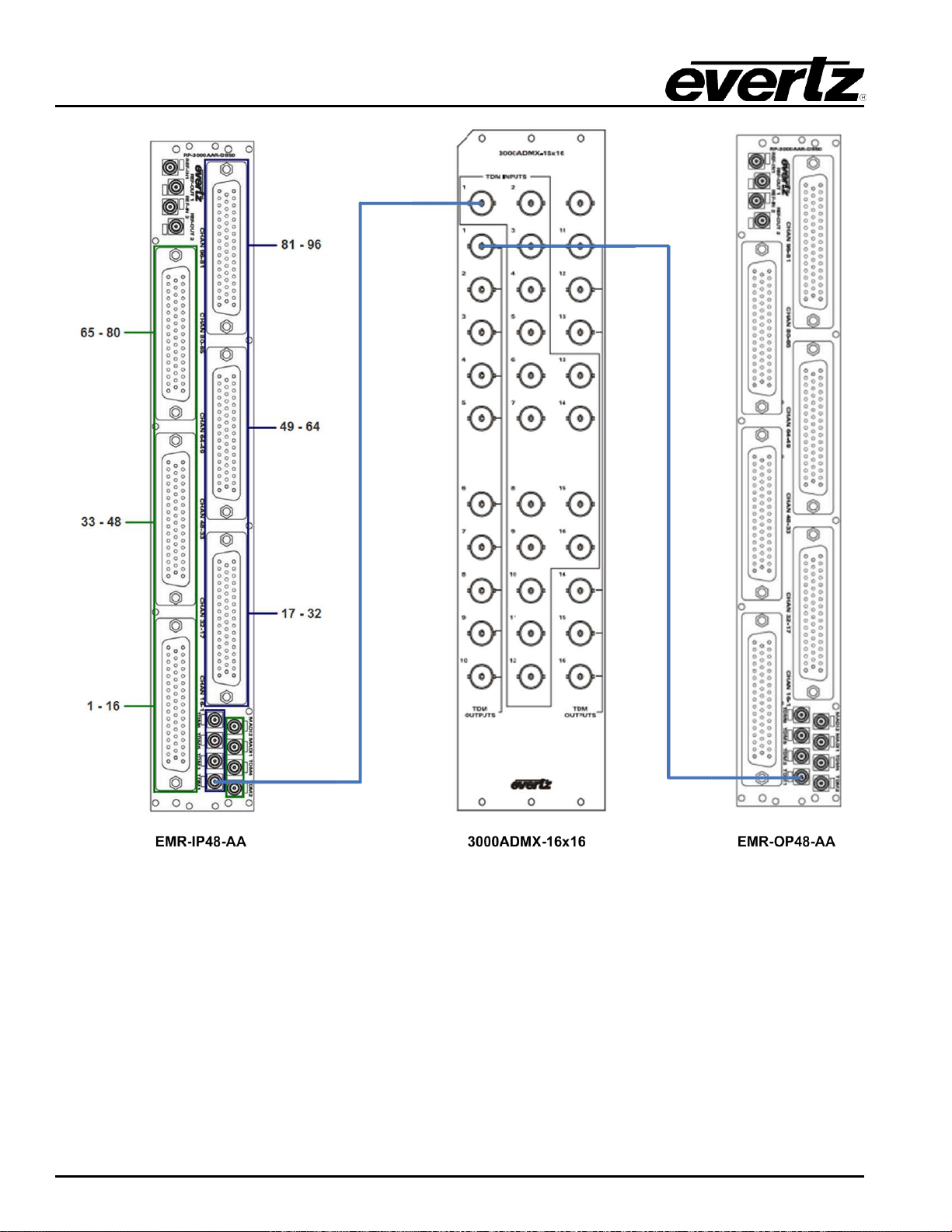
EMR User's Guide
High Density Modular Audio Router (AES, Analog, MADI, TimeCode, Data)
Figure
2-17: Basic EMR-AA Setup with 3000 ADMX
Page 34 Revision 1.8 COMPONENT OVERVIEW
Page 49
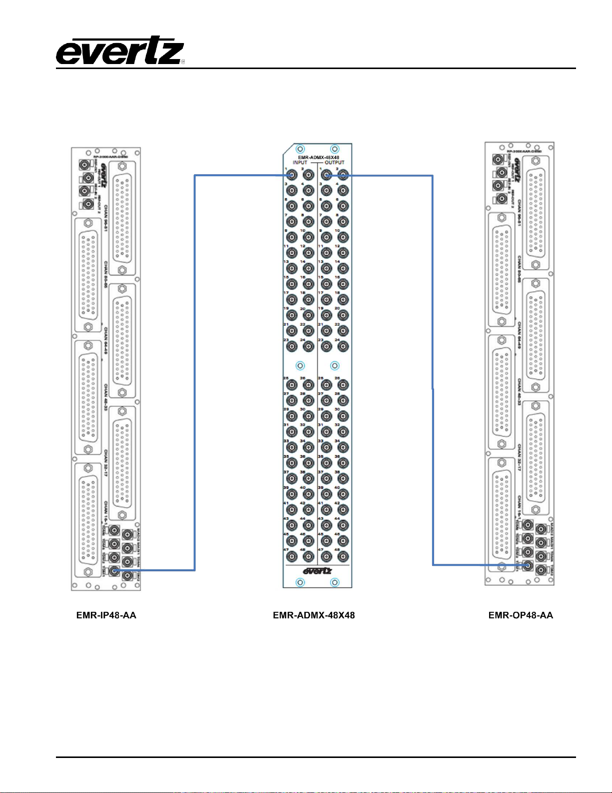
EMR User's Guide
High Density Modular Audio Router (AES, Analog, MADI, TimeCode, Data)
Figure
2-18: Basic EMR-AA Setup with ADMX-48X48
COMPONENT OVERVIEW Revision 1.8 Page 35
Page 50
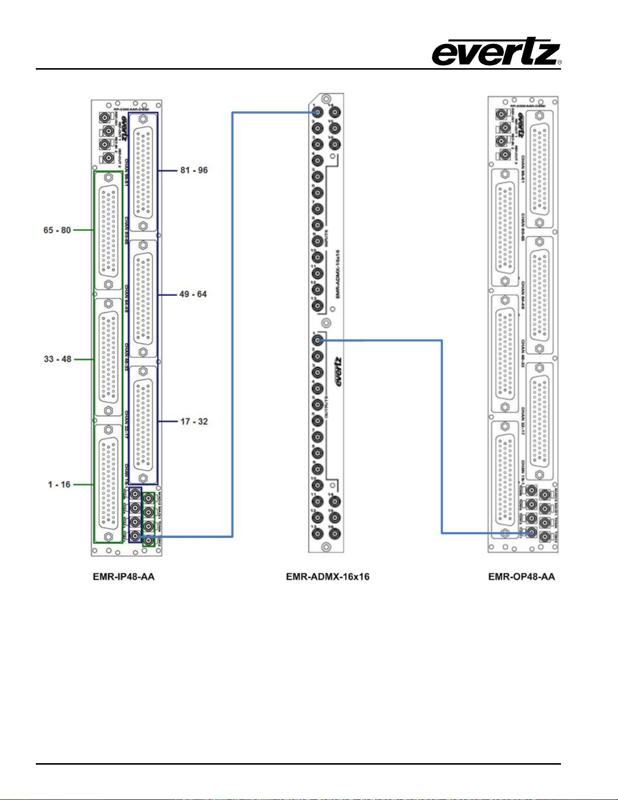
EMR User's Guide
High Density Modular Audio Router (AES, Analog, MADI, TimeCode, Data)
Figure
2-19: Basic EMR-AA Setup without ADMX-16X16/A
Page 36 Revision 1.8 COMPONENT OVERVIEW
Page 51
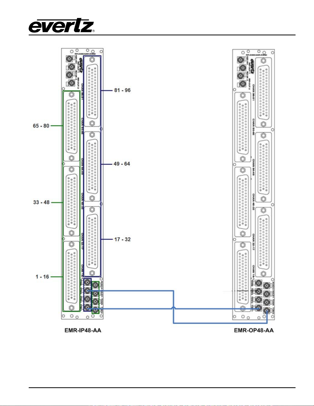
EMR User's Guide
High Density Modular Audio Router (AES, Analog, MADI, TimeCode, Data)
Figure 2-20: Basic EMR-AA Setup without ADMX
COMPONENT OVERVIEW Revision 1.8 Page 37
Page 52
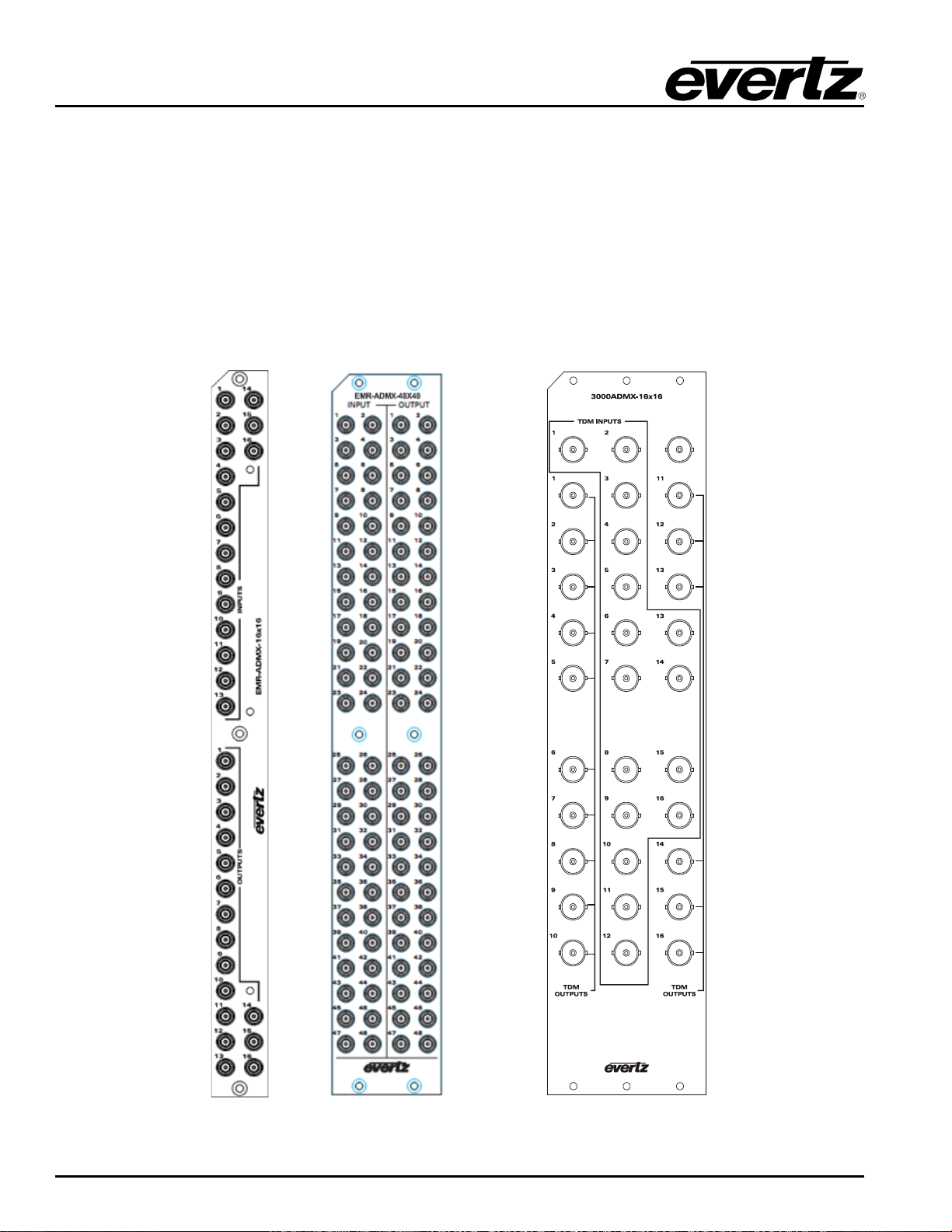
EMR User's Guide
High Density Modular Audio Router (AES, Analog, MADI, TimeCode, Data)
2.2.5. EMR-ADMX-16X16/A, EMR-ADMX-48X48 and 3000ADMX-16X16 Crosspoint Modules
The EMR-ADMX-16X16/A, EMR-ADMX-48X48 and 3000ADMX-16X16 are the crosspoint cards for the
EMR. They utilize a TDM core to allow up to 30720x30720 mono audio channels to be routed. EMRADMX-16X16/A and the 3000ADMX-16X16 have 16 TDM inputs and EMR-ADMX-48X48 has 48 TDM
inputs which allow them to be interfaced with any of the EMR input modules or AVIP and 16 TDM and 48
TDM outputs that allow them to be interfaced with any of the EMR output modules or AVOP.
The E MR-ADMX-16X16/A rear panel occupies 1 slot in a frame and uses DIN 1.0/2.3 connectors, EMRADMX-48X48 rear panel occupies 2 slots in a frame and uses DIN 1.0/2.3 connectors while the
3000ADMX-16X16 rear panel occupies 3 slots in a frame and has BNC connectors. All three plates are
shown in Figure
2-21.
Figure
2-21: EMR-ADMX-16X16/A (left), EMR-ADMX-48X48 (center) and 3000ADMX-16X16 (right)
Page 38 Revision 1.8 COMPONENT OVERVIEW
Page 53
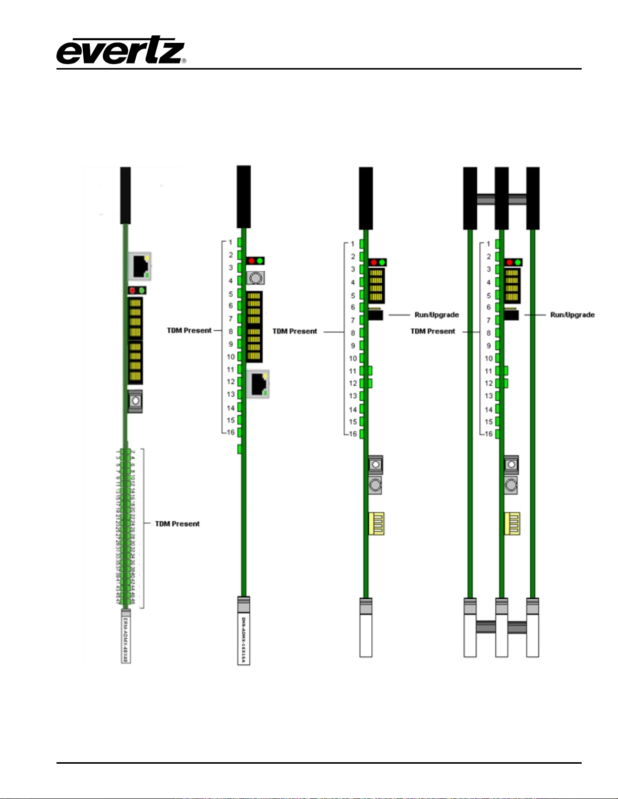
EMR User's Guide
High Density Modular Audio Router (AES, Analog, MADI, TimeCode, Data)
2.2.5.1. Front Card Edge Controls and LEDs
The EMR-ADMX-48X48, EMR-ADMX-16X16/A and the 3000ADMX-16X16 front card edges have some
key controls and indicators that can help in the installation and debugging processes. Figure
Table
2-11 show the card edges and describe the expected behavior of each component. If the status
indicators do not behave as described it can be a sign of installation or configuration issues.
2-22 and
Figure
2-22: From left to right EMR-ADMX-48X48, EMR-ADMX-16X16A, EMR-ADMX-16X16 and
3000ADMX-16X16) Front Card Edges
COMPONENT OVERVIEW Revision 1.8 Page 39
Page 54
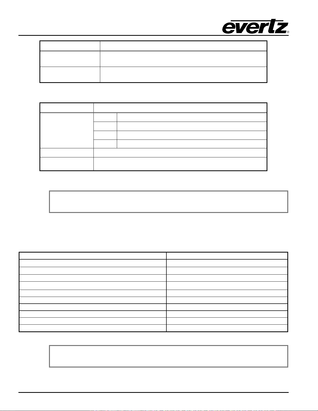
EMR User's Guide
Switches the display to view, FIFO/Mem, Version, IP address A,
IP address B, Input error and Interlink error
Note: If it appears that the TDM presence LEDs do not light up with valid TDM
ifconfig 0 inet x.x.x.x netmask y.y.y.y broadcast z.z.z.z
Configures Netwrok 1
ifconfig 1 inet x.x.x.x netmask y.y.y.y broadcast z.z.z.z
Configures Netwrok 2
ifconfig
Displays the current network setting
iproute add default xxx.xxx.xxx.xxx
Sets the default gateway address
iproute load
Displays the current default gateway address
iproute add default 0.0.0.0
Removes the default gateway
TDM version 1
Sets TDM to version 1 ( Reboot required)
TDM version 2
Sets TDM to version 2 ( Future use)
TDM version
Displays the current TDM version
version
Displays the installed firmware version
reset
Resets the unit
High Density Modular Audio Router (AES, Analog, MADI, TimeCode, Data)
Component Description
TDM Present LEDs
Run/Upgrade Jumper
Table 2-11: Description of EMR-ADMX-16X16 and 3000ADMX-16X16 Card Edges
Component
TDM Present LEDs
Ethernet Port
Rotary Switch
Table 2-12: Description of ADMX-48X48 and ADMX-16X16A Card Edges
connections, ensure that the module is firmly connected to the rear plate.
This set of LEDs are green in color and indicate the presence of a
valid TDM connection on each respective input
This jumper is used to place the module in upgrade mode when
upgrading the firmware
Description
Red No signal or link error
Blue Audio packet without LSID
Green Audio packet with LSID
Amber LSID with no Audio packet
No function
2.2.5.2. EMR-ADMX-48X48 and EMR-ADMX-16X16 A User Commands:
Menus in ADMX-48X48 and ADMX-16X16A are command based. Important commands are listed in the
table below in order to configure some parameter in the card:
Note: The default TDM version is V1. TDM V2 is for future use.
Page 40 Revision 1.8 COMPONENT OVERVIEW
Page 55
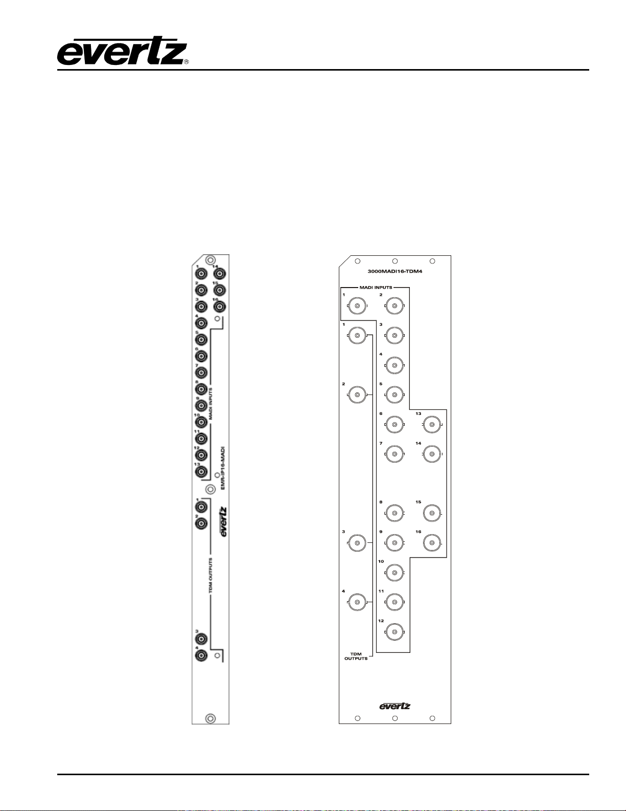
EMR User's Guide
High Density Modular Audio Router (AES, Analog, MADI, TimeCode, Data)
2.2.6. EMR-IP16-MADI and 3000MADI16-TDM4 MADI Input Modules
The E MR-IP16-MADI and 3000MADI16-TDM4 are MADI audio input cards for the EMR. They support 16
MADI inputs and 4 TDM outputs. Each MADI input can support both 64 channels and 56 channels MADI.
Of the 4 TDM outputs, only outputs 1 and 2 are required for operation. Outputs 3 and 4 can be used as
redundant TDM connections for systems that have more than 1 crosspoint module. TDM output 1 carries
512 audio signals corresponding to MADI inputs 1-8. TDM output 2 carries 512 audio signals
corresponding to MADI inputs 9-16.
The EMR-IP16-MADI rear panel occupies 1 slot in a frame and has DIN 1.0/2.3 connectors, while the
3000MADI16-TDM4 rear panel occupies 3 slots in a frame and has BNC connectors. Both are shown in
Figure
2-23.
Figure 2-23: EMR-IP16-MADI (left) and 3000MADI16-TDM4 (right) Rear Plates
COMPONENT OVERVIEW Revision 1.8 Page 41
Page 56
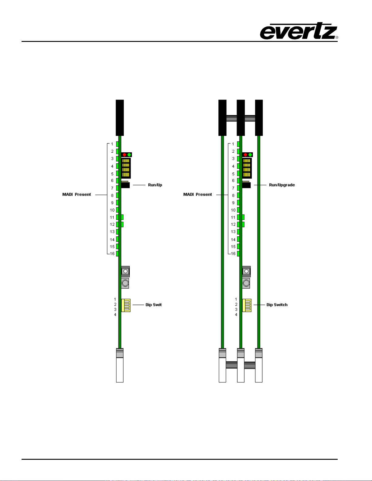
EMR User's Guide
High Density Modular Audio Router (AES, Analog, MADI, TimeCode, Data)
2.2.6.1. Front Card Edge Controls and LEDs
The EMR-IP16-MADI and 3000MADI16-TDM4 front card edges have some key controls and indicators
that can help in the installation and debugging processes. Figure
edges and describe the expected behavior of each component. If the status indicators do not behave as
described it can be a sign of installation or configuration issues.
2-24 and Table 2-13 show the card
New Card Old Card
Figure
2-24: EMR-IP16-MADI (left) and 3000MADI16-TDM4 (right) Front Card Edges
Page 42 Revision 1.8 COMPONENT OVERVIEW
Page 57
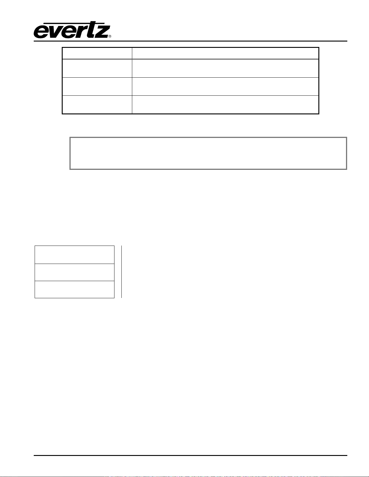
EMR User's Guide
TDM4 module, dip switch 1 must be
High Density Modular Audio Router (AES, Analog, MADI, TimeCode, Data)
Component Description
MADI Present LEDs
Run/Upgrade Jumper
Dip Switch
Table 2-13: Description of EMR-IP16-MADI and 3000MADI16-TDM4 Card Edge
Note: For normal operation of the 3000MADI16-
2.2.6.2. Configuration and Monitoring Menu
EMR-IP16-MADI contains configuration and monitoring menu that allows the user to change some internal
settings of the device and also to monitor various components on the card.
The configuration and monitoring menu can be accessed using either Telnet session or serial connection.
Once gained access to the main menu, use the numbers beside the items to set the value. Follow the on
screen instructions to set the value of the parameter, save and exit the configuration.
set to the up position (OPEN) and dip switches 2-4 must be set to the down position.
This set of LEDs are green in color and indicate the presence of a
valid MADI connection on each respective input
This jumper is used to place the module in upgrade mode when
upgrading the firmware
This set of switches control the mode of the device. Dip 1 must be
up and 3-4 must be down.
Network Configuration Configuration of Network 1
Audio Diagnostics Shows the MADI Input status, Current route map and Genlock status
Engineering Menu Accessed by Evertz technical support staff only
2.2.7. EMR-OP16-MADI and 3000TDM4-MADI16 MADI Output Modules
The E MR-OP16-MADI and 3000TDM4-MADI16 are MADI audio output cards for the EMR. They support
4 TDM inputs and 16 MADI outputs. Each MADI output supports 56 or 64 channel MADI depending on a
setting in the serial menu.
Of the 2 TDM inputs, only inputs 1 and 2 are required for operation. Inputs 3 and 4 can be used as
redundant TDM connections for systems that have more than 1 crosspoint module. TDM input 1 carries
512 audio signals corresponding to MADI outputs 1-8. TDM input 2 carries 512 audio signals
corresponding to MADI outputs 9-16.
The EMR-OP16-MADI rear panel occupies 1 slot in a frame and has DIN 1.0/2.3 connectors. The
3000TDM4-MADI16 rear panel occupies 3 slots in a frame and has BNC connectors. Both are shown in
Figure
2-25 below.
COMPONENT OVERVIEW Revision 1.8 Page 43
Page 58
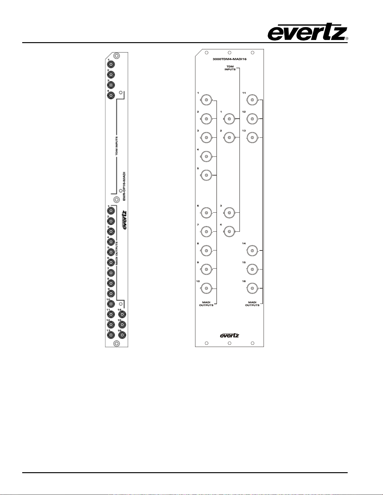
EMR User's Guide
High Density Modular Audio Router (AES, Analog, MADI, TimeCode, Data)
Figure
2-25: EMR-OP16-MADI (left) and 3000TDM4-MADI16 (right) Rear Plates
Page 44 Revision 1.8 COMPONENT OVERVIEW
Page 59
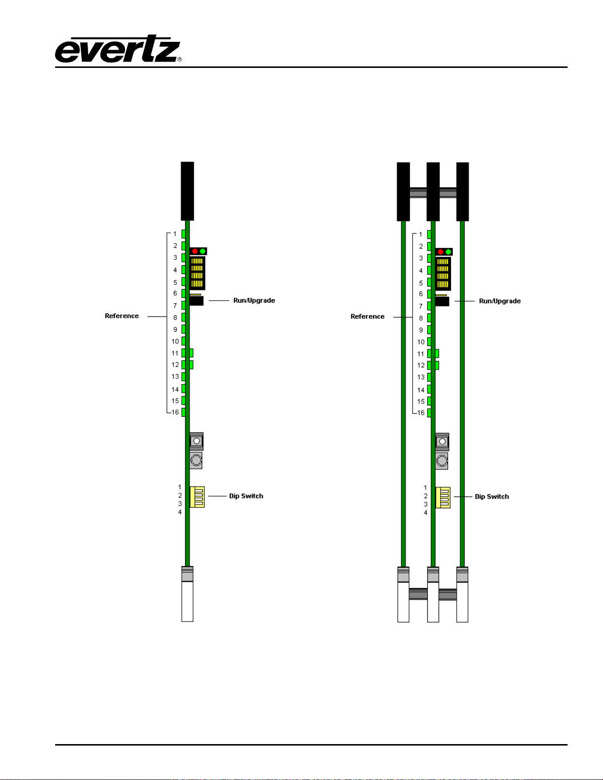
EMR User's Guide
High Density Modular Audio Router (AES, Analog, MADI, TimeCode, Data)
2.2.7.1. Front Card Edge Controls and LEDs
The EMR-OP16-MADI and 3000TDM4-MADI16 front card edges have some key controls and indicators
that can help in the installation and debugging processes. Figure
edges and describe the expected behavior of each component. If the status indicators do not behave as
described it can be a sign of installation or configuration issues.
2-26 and Table 2-14 show the card
Figure
2-26: EMR-OP16-MADI (left) and 3000TDM4-MADI16 (right) Front Card Edges
COMPONENT OVERVIEW Revision 1.8 Page 45
Page 60
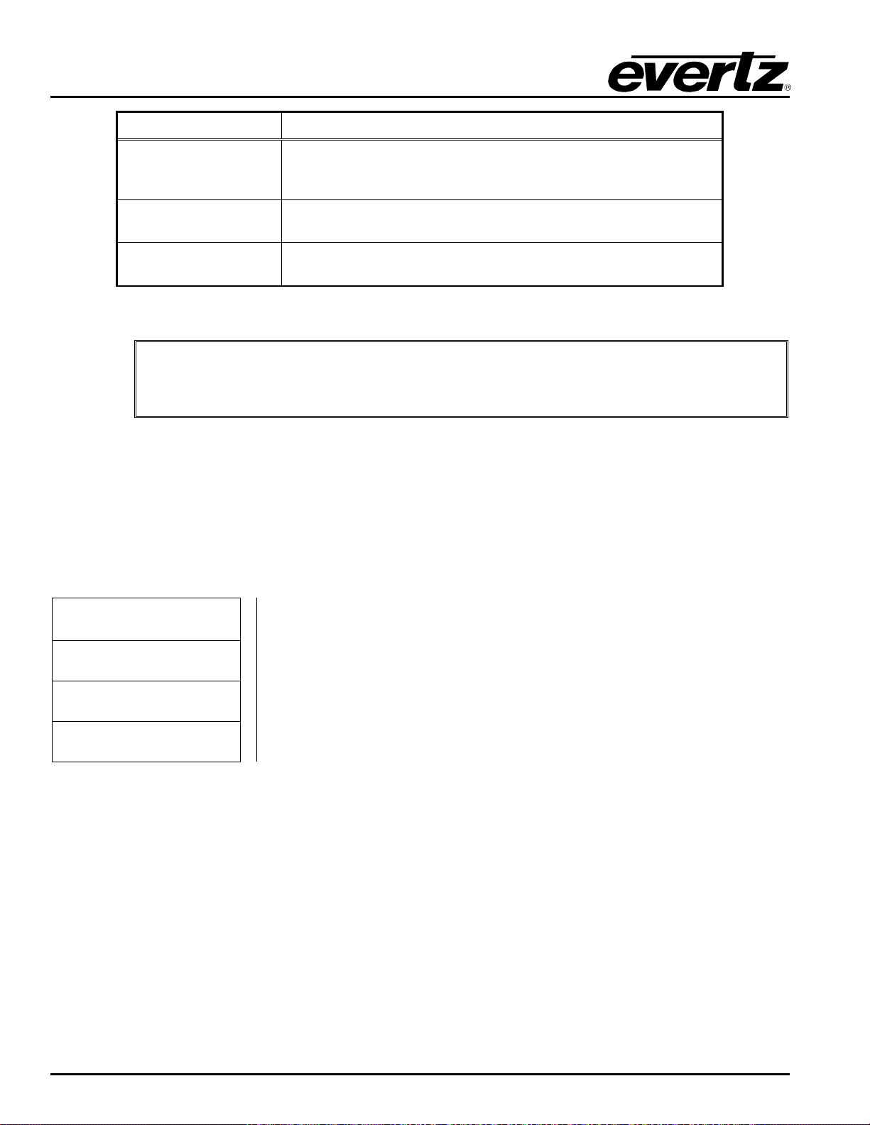
EMR User's Guide
MADI16 module, dip switch 1 must be
High Density Modular Audio Router (AES, Analog, MADI, TimeCode, Data)
Component Description
These sets of LEDs are green in color and will in 1 second interval
Reference LEDs
if a valid reference is detected. If no reference is detected they will
cycle between on for 1 second and off for 3 seconds.
Run/Upgrade Jumper
Dip Switch
Table 2-14: Description of EMR-OP16-MADI and 3000TDM4-MADI16 Card Edges
Note: For normal operation of the 3000TDM4-
2.2.7.2. Configuration and Monitoring Menu
EMR-OP16-MADI contains configuration and monitoring menu that allows the user to change some
internal settings of the device and also to monitor various components on the card.
The configuration and monitoring menu can be accessed using either Telnet session or serial connection.
Once gained access to the main menu, use the numbers beside the items to set the value. Follow the on
screen instructions to set the value of the parameter, save and exit the configuration.
Network Configuration Configuration of Network 1
set to the up position (OPEN) and dip switches 2-4 must be set to the down position.
This jumper is used to place the module in upgrade mode when
upgrading the firmware
This set of switches control the mode of the device. Dip 1 must be
up and 3-4 must be down.
MADI output Format Configuration of MADI output to 56 Channels or 64 Channels
Audio Diagnostics Shows current route map, LSID presence status and data rate
Engineering Menu Accessed by Evertz technical support staff only
2.2.8. EMR-IP96 (48)-LTC Time Code Input Module
The EMR-IP96 (48)-LTC is a time code input card for the EMR. It supports 96 or 48 balanced LTC inputs.
The E MR-IP96 ( 48)-LTC input card does not require the use of a 3000ADMX-16X16 for systems with less
than 768 LTC inputs. Each LTC input card connects directly to each LTC output card via one of 8
identical TDM outputs.
The E MR-IP96-LTC rear panel occupies 2 slots in a frame and has 50-pin D-Sub female connectors as
shown in Figure
connector supports 16 LTC input signals. The pin out for each connector is shown in Table
TDM outputs all use DIN 1.0/2.3 connectors.
2-27. The LTC inputs are interfaced by the six 50-pin D-Sub female connectors. Each
2-15. The
Page 46 Revision 1.8 COMPONENT OVERVIEW
Page 61
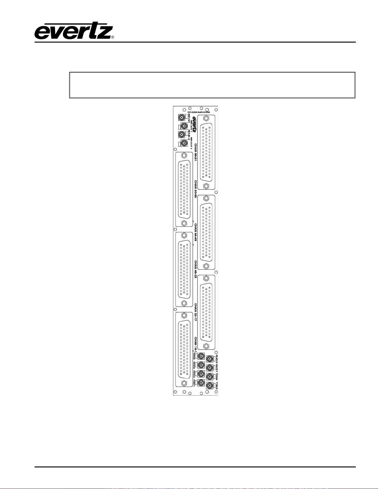
EMR User's Guide
High Density Modular Audio Router (AES, Analog, MADI, TimeCode, Data)
The EMR-IP48-LTC uses the same rear plate but only the first three 50-pin D-Sub connectors are
enabled.
Note: The IP and OP LTC cards use balanced rear plates.
Figure
COMPONENT OVERVIEW Revision 1.8 Page 47
2-27: EMR-IP96 (48)-LTC Rear Plate
Page 62
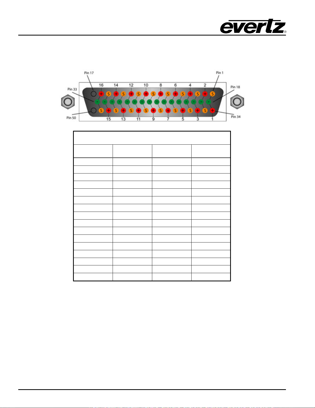
EMR User's Guide
High Density Modular Audio Router (AES, Analog, MADI, TimeCode, Data)
2.2.8.1. LTC Input D50 Connector – Pin Out
The EMR-IP96 (48)-LTC time code cards use female D50 connectors, with each connector carrying 16
signals. Table
2-15 outlines the pinout for the connectors.
D50 LTC Pin-Out Table
Signal +ve Pin -ve Pin Screen
1 34 18 1
2 2 19 35
3 36 20 3
4 4 21 37
5 38 22 5
6 6 23 39
7 40 24 7
8 8 25 41
9 42 26 9
10 10 27 43
11 44 28 11
12 12 29 45
13 46 30 13
14 14 31 47
15 48 32 15
16 16 33 49
Table 2-15: LTC Input Pin-Out
Page 48 Revision 1.8 COMPONENT OVERVIEW
Page 63
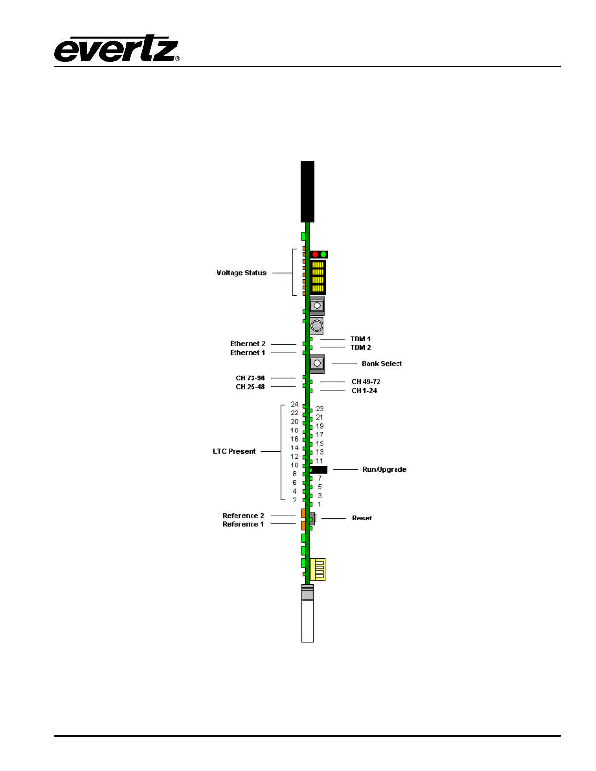
EMR User's Guide
High Density Modular Audio Router (AES, Analog, MADI, TimeCode, Data)
2.2.8.2. Front Card Edge Controls and LEDs
The EMR-IP96 (48)-LTC front card edge has some key controls and indicators that can help in the
installation and debugging processes. Figure
expected behavior of each component. If the status indicators do not behave as described it can be a
sign of installation or configuration issues.
2-28 and Table 2-16 show the card edge and describe the
Figure
2-28: EMR-IP96 (48)-LTC Front Card Edge
COMPONENT OVERVIEW Revision 1.8 Page 49
Page 64

EMR User's Guide
This LED is amber in color and indicates the presence of a valid
slowly if it is the primary reference
This LED is amber in color and indicates the presence of a valid
slowly if it is the primary reference
High Density Modular Audio Router (AES, Analog, MADI, TimeCode, Data)
Component Description
Voltage Status LEDs
Ethernet 1 LED
Ethernet 2 LED
TDM 1
TDM 2
Bank Select Push
Button
CH 1-24 LED
CH 25-48 LED
CH 49-72 LED
CH 73-96 LED
This set of LEDs are amber in color and should always be ON
This LED is green in color and flashes when there is a ctiv it y on
Ethernet port 1
This LED is green in color and flashes when there is activity on
Ethernet port 2
This LED is green in color and flashes when a valid TDM signal is
detected on TDM input 1 and is solid when it is the primary TDM
This LED is green in color and flashes when a valid TDM signal is
detected on TDM input 2 and is solid when it is the primary TDM
Selects the bank of inputs that are being monitored by the LTC
Present LEDs
This LED is green in color and indicates that inputs 1 to 24 are
currently being monitored by the LTC Present LEDs
This LED is green in color and indicates that inputs 25 to 48 are
currently being monitored by the LTC Present LEDs
This LED is green in color and indicates that inputs 49 to 72 are
currently being monitored by the LTC Present LEDs
This LED is green in color and indicates that inputs 73 to 96 are
currently being monitored by the LTC Present LEDs
LTC Present LEDs
Reference 1 LED
Reference 2 LED
Run/Upgrade Jumper
Reset Button
This set of LEDs are green in color and indicate the presence of
LTC on each respective input
reference on input 1. It will flash rapidly if reference is present and
reference on input 2. It will flash rapidly if reference is present and
This jumper is used to place the module in upgrade mode when
upgrading the firmware
This button resets the module
Table 2-16: Description of EMR-IP96 (48)-LTC Card Edge
2.2.8.3. Configuration and Monitoring Menu
EMR-IP48-LTC contains configuration and monitoring menu that allows the user to change some internal
settings of the device and also to monitor various components on the card.
The configuration and monitoring menu can be accessed using either Telnet session or serial connection.
Once gained access to the main menu, use the numbers beside the items to set the value. Follow the on
screen instructions to set the value of the parameter, save and exit the configuration.
Page 50 Revision 1.8 COMPONENT OVERVIEW
Page 65

EMR User's Guide
Views LTC port routing, port status table, frame reference status, frame
High Density Modular Audio Router (AES, Analog, MADI, TimeCode, Data)
Network Configuration Configuration of Network 1 and 2
SNMP Configuration Configuration of Simple Network Management Protocol.
LTC Port Configuration
reference and plink status.
Trace - Engineering Only Configured under the supervision of Evertz technical support staff only
Engineering Debug Utility Accessed by Evertz technical support staff only
2.2.9. EMR-OP96 (48)-LTC TimeCode Output Module
The EMR-OP96 (48)-LTC is a time code output card for the EMR. It supports 96 or 48 balanced LTC
outputs.
The EMR-OP96 (48)-LTC output card does not require the use of an ADMX for systems with less than
768 LTC outputs. Each LTC output card connects directly to each LTC input card via one of 8 TDM
inputs.
The E MR-OP96-LTC rear panel occupies 2 slots in a frame and has 50-pin D-Sub female connectors as
shown in Figure
connector supports 16 LTC output signals. The pin out for each connector is shown in Table
TDM inputs all use DIN 1.0/2.3 connectors and are identified using Table
2-29. The LTC outputs are interfaced by the six 50-pin D-Sub female connectors. Each
2-18. The
2-17. The sequence in which
input cards are connected to the output card determine the sequence of the LTC inputs. The EMR-OP48LTC uses the same rear plate but only the first three 50-pin D-Sub connectors are enabled.
COMPONENT OVERVIEW Revision 1.8 Page 51
Page 66
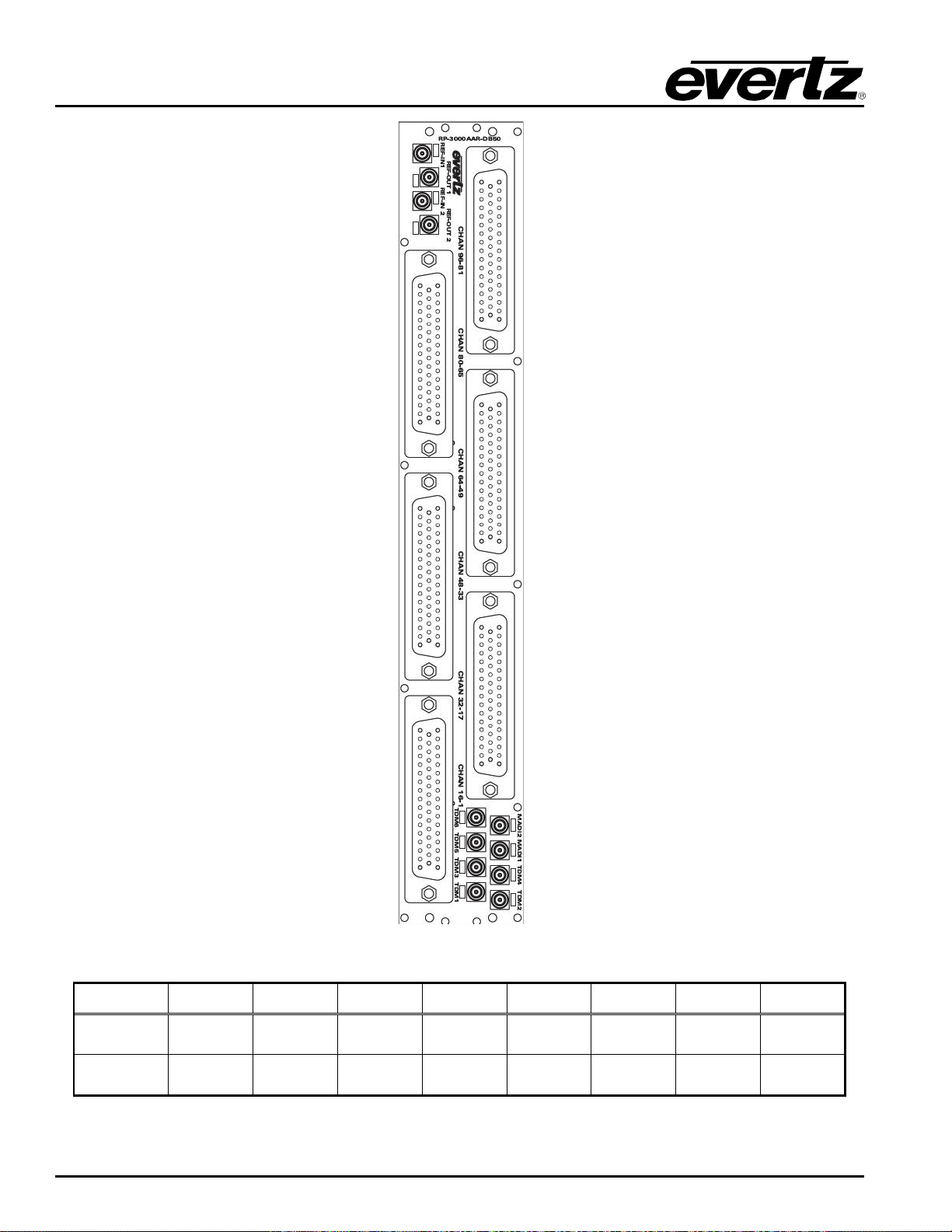
EMR User's Guide
TDM
Inputs
TDM IN
1
TDM IN
2
TDM IN
3
TDM IN
4
TDM IN
5
TDM IN
6
TDM IN
7
TDM IN
8
LTC
Inputs
High Density Modular Audio Router (AES, Analog, MADI, TimeCode, Data)
Figure
2-29: EMR-O P96 (48)-LTC Rear Plate
Label TDM 1 TDM 3 TDM 2 TDM 4 TDM 5 TDM 6 MADI 1 MADI 2
1-96 97-192 193-288 289-384 385-480 481-576 577-672 673-768
Table 2-17: EMR-OP96 (48)-LTC TDM Connections
Page 52 Revision 1.8 COMPONENT OVERVIEW
Page 67
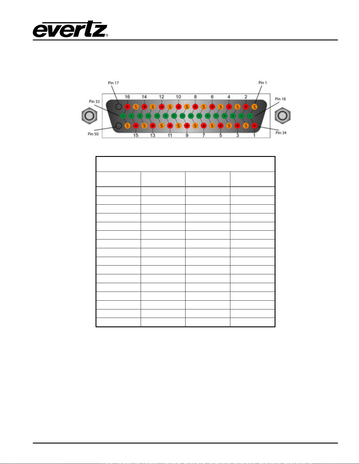
EMR User's Guide
High Density Modular Audio Router (AES, Analog, MADI, TimeCode, Data)
2.2.9.1. LTC Output D50 Connector – Pin Out
The E MR-OP96 (48)-LTC time code cards use female D50 connectors, with each connector carrying 16
signals. Table
2-18 outlines the pinout for the connectors.
D50 LTC Pin-Out Table
Signal +ve Pin -ve Pin Screen
1 34 18 1
2 2 19 35
3 36 20 3
4 4 21 37
5 38 22 5
6 6 23 39
7 40 24 7
8 8 25 41
9 42 26 9
10 10 27 43
11 44 28 11
12 12 29 45
13 46 30 13
14 14 31 47
15 48 32 15
16 16 33 49
Table 2-18: LTC Output P in-Out
COMPONENT OVERVIEW Revision 1.8 Page 53
Page 68
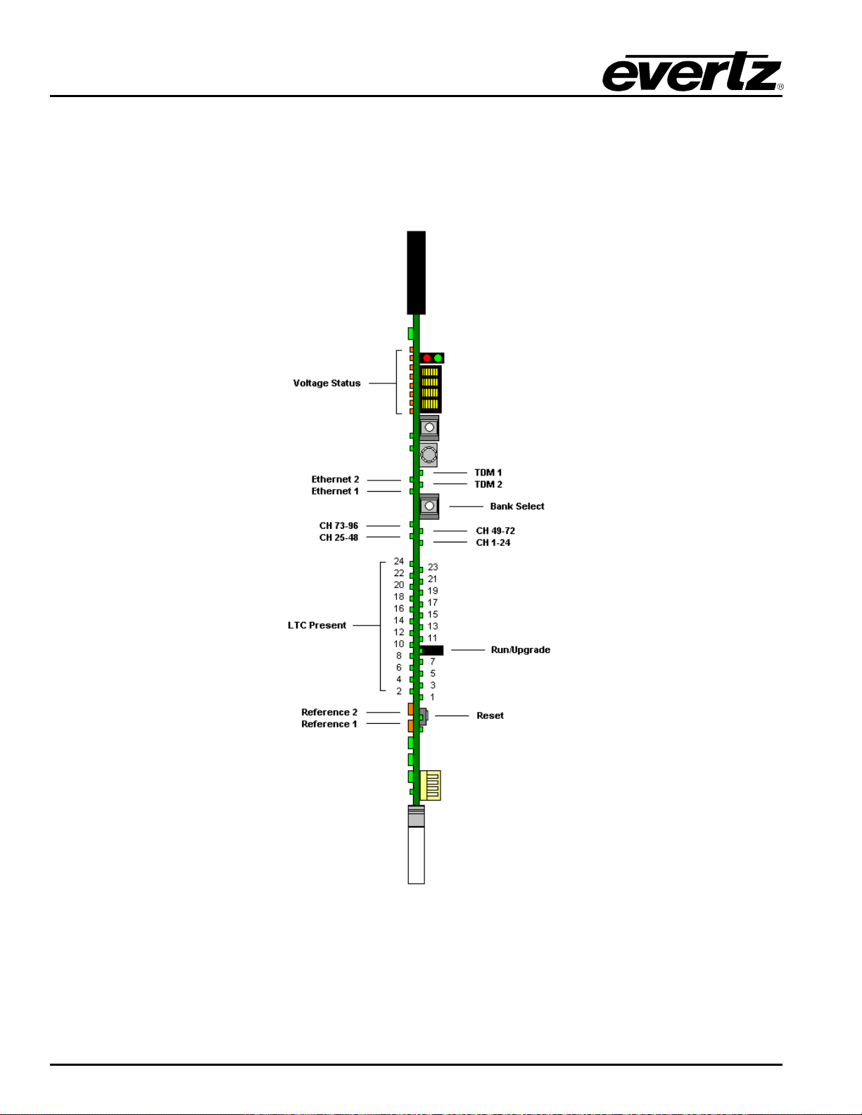
EMR User's Guide
High Density Modular Audio Router (AES, Analog, MADI, TimeCode, Data)
2.2.9.2. Front Card Edge Controls and LEDs
The EMR-OP96 (48)-LTC front card edge has some key controls and indicators that can help in the
installation and debugging processes. Figure
expected behavior of each component. If the status indicators do not behave as described it can be a
sign of installation or configuration issues.
2-30 and Table 2-19 show the card edge and describe the
Figure
2-30: EMR-O P96 (48)-LTC Front Card Edge
Page 54 Revision 1.8 COMPONENT OVERVIEW
Page 69
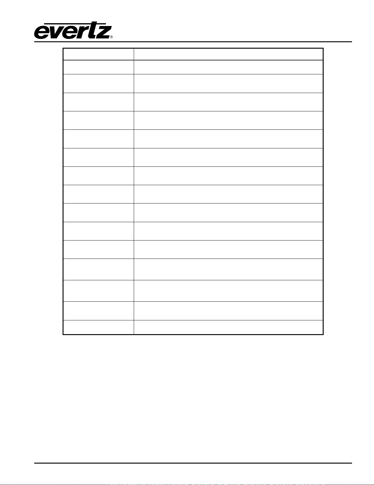
EMR User's Guide
This LED is amber in color and indicates the presence of a valid
slowly if it is the primary reference
This LED is amber in color and indicates the presence of a valid
slowly if it is the primary reference
High Density Modular Audio Router (AES, Analog, MADI, TimeCode, Data)
Component Description
Voltage Status LEDs
Ethernet 1 LED
Ethernet 2 LED
TDM 1
TDM 2
Bank Select Push
Button
CH 1-24 LED
CH 25-48 LED
CH 49-72 LED
CH 73-96 LED
This set of LEDs are amber in color and should always be ON
This LED is green in color and flashes when there is a ctiv it y on
Ethernet port 1
This LED is green in color and flashes when there is activity on
Ethernet port 2
This LED is green in color and flashes when a valid TDM signal is
detected on TDM input 1 and is solid when it is the primary TDM
This LED is green in color and flashes when a valid TDM signal is
detected on TDM input 2 and is solid when it is the primary TDM
Selects the bank of inputs that are being monitored by the LTC
Present LEDs
This LED is green in color and indicates that inputs 1 to 24 are
currently being monitored by the LTC Present LEDs
This LED is green in color and indicates that inputs 25 to 48 are
currently being monitored by the LTC Present LEDs
This LED is green in color and indicates that inputs 49 to 72 are
currently being monitored by the LTC Present LEDs
This LED is green in color and indicates that inputs 73 to 96 are
currently being monitored by the LTC Present LEDs
LTC Present LEDs
Reference 1 LED
Reference 2 LED
Run/Upgrade Jumper
Reset Button
This set of LEDs are green in color and indicate the presence of
LTC on each respective input
reference on input 1. It will flash rapidly if reference is present and
reference on input 2. It will flash rapidly if reference is present and
This jumper is used to place the module in upgrade mode when
upgrading the firmware
This button resets the module
Table 2-19: Description of EMR-OP96 (48)-LTC Card Edge
2.2.9.3. Configuration and Monitoring Menu
EMR-OP48-LTC contains configur ation and monitoring menu that allows the user to change some internal
settings of the device and also to monitor various components on the card.
The configuration and monitoring menu can be accessed using either Telnet session or serial connection.
Once gained access to the main menu, use the numbers beside the items to set the value. Follow the on
screen instructions to set the value of the parameter, save and exit the configuration.
COMPONENT OVERVIEW Revision 1.8 Page 55
Page 70
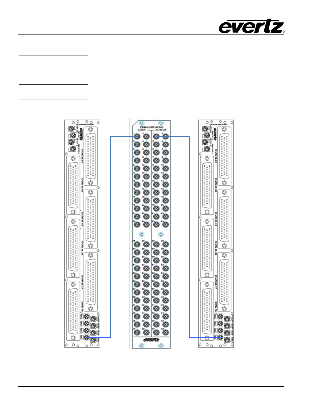
EMR User's Guide
Views LTC port routing, port status table, frame reference status, Card ID,
LTC output amplitude and plink status.
EMR-IP96(48)-LTC EMR-OP96(48)-LTC
EMR ADMX-48X48
High Density Modular Audio Router (AES, Analog, MADI, TimeCode, Data)
Network Configuration Configuration of Network 1 and 2
SNMP Configuration Configuration of Simple Network Management Protocol.
LTC Port Configuration
Trace - Engineering Only Configured under the supervision of Evertz technical support staff only
Engineering Debug Utility Accessed by Evertz technical support staff only
Figure
Page 56 Revision 1.8 COMPONENT OVERVIEW
2-31: Basic LTC Setup with ADMX-48X48
Page 71
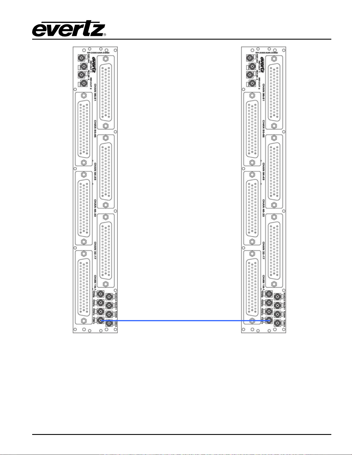
EMR User's Guide
EMR-IP
96(
48)
-LTC EMR
-OP
96(48)-LTC
High Density Modular Audio Router (AES, Analog, MADI, TimeCode, Data)
Figure
2-32: Basic LTC Setup without ADMX
2.2.10. EMR-PR48 Data Module
The EMR-PR48 is a data port router card for the EMR. Each of the 48 data ports that are available on the
module can be configured to sup1port either RS-422 or RS-232 serial protocols. Additionally, each port
can be configured to be a master or slave so that devices can be set to controlling or controlled devices.
COMPONENT OVERVIEW Revision 1.8 Page 57
Page 72
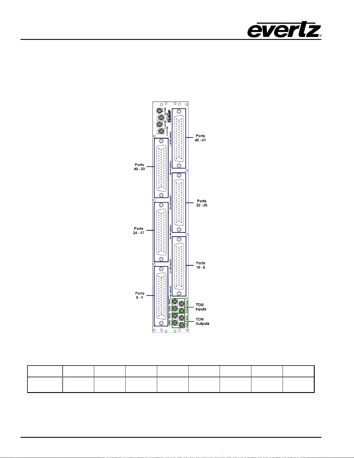
EMR User's Guide
RP-3000APR-DB50
TDM
OUT 1
TDM
OUT 2
TDM
OUT 3
TDM
OUT 4
TDM IN
1
TDM IN
2
TDM IN
3
TDM IN
4
High Density Modular Audio Router (AES, Analog, MADI, TimeCode, Data)
The EMR-PR48 rear panel occupies 2 slots in a frame and uses 50-pin D-Sub female connectors as
shown in Figure
The E MR-PR48 rear plate also has 6 TDM outputs and 6 TDM inputs via DIN 1.0/2.3 connectors. These
connectors allow for further port expansion. The EMR-PR48 can expand to a system of 288 ports without
the need for an ADMX crosspoint and 336x336 with an ADMX crosspoint. Details of the expansion are
shown in Section
2-33. Each connector supports 8 serial data ports (RS-232 or RS-422).
4.2.1.
Figure
2-33: EMR-PR48 Rear Plate
Label TDM 1 TDM 3 TDM 2 TDM 4 TDM 5 TDM 6 MADI 1 MADI 2
Actual I/O
Table 2-20: EMR-PR48 TDM Connections
Page 58 Revision 1.8 COMPONENT OVERVIEW
Page 73
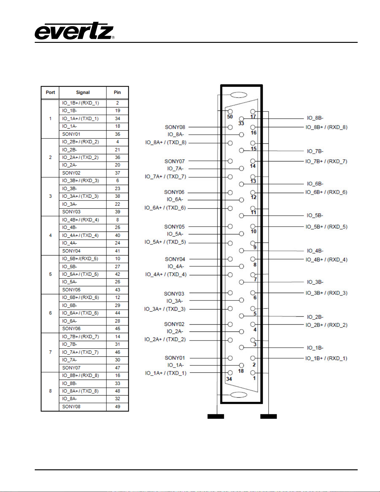
EMR User's Guide
High Density Modular Audio Router (AES, Analog, MADI, TimeCode, Data)
2.2.10.1. Data Port D50 Connector – Pin Out
EMR-PR48 analog audio frames use female D50 connectors, with each connector carrying 8 data ports.
The details of how each of the D50 pins map to each of the 8 ports is shown in Figure
2-34 .
Figure
2-34: Data Port Pin-Out
COMPONENT OVERVIEW Revision 1.8 Page 59
Page 74
EMR User's Guide
CTRL
SLAVE
D50
RS422
RS232
D9
Rx+
Tx+
2
Tx+
TXD
Pin 3
Rx-
Tx-
19
Tx- Pin 8
Tx+
Tx+
34
Rx+
RXD
Pin 7
Tx-
Tx-
18
Rx-
Pin 2
Sony
Sony
35
Sony
Pin 5
0v
0v 1 0v
0v
Pin 4 & 6
Rx+
Tx+
4
Tx+
TXD
Pin 3
Rx-
Tx-
21
Tx- Pin 8
Tx+
Tx+
36
Rx+
RXD
Pin 7
Tx-
Tx-
20
Rx-
Pin 2
Sony
Sony
37
Sony
Pin 5
0v
0v 3 0v
0v
Pin 4 & 6
Rx+
Tx+
6
Tx+
TXD
Pin 3
Rx-
Tx-
23
Tx- Pin 8
Tx+
Tx+
38
Rx+
RXD
Pin 7
Tx-
Tx-
22
Rx-
Pin 2
Sony
Sony
39
Sony
Pin 5
0v
0v 5 0v
0v
Pin 4 & 6
Rx+
Tx+
8
Tx+
TXD
Pin 3
Rx-
Tx-
25
Tx- Pin 8
Tx+
Tx+
40
Rx+
RXD
Pin 7
Tx-
Tx-
24
Rx-
Pin 2
Sony
Sony
41
Sony
Pin 5
0v
0v 7 0v
0v
Pin 4 & 6
Rx+
Tx+
10
Tx+
TXD
Pin 3
Rx-
Tx-
27
Tx- Pin 8
Tx+
Tx+
42
Rx+
RXD
Pin 7
Tx-
Tx-
26
Rx-
Pin 2
Sony
Sony
43
Sony
Pin 5
0v
0v 9 0v
0v
Pin 4 & 6
Rx+
Tx+
12
Tx+
TXD
Pin 3
Rx-
Tx-
29
Tx-
Pin 8
Tx+
Tx+
44
Rx+
RXD
Pin 7
Tx-
Tx-
28
Rx-
Pin 2
Sony
Sony
45
Sony
Pin 5
0v
0v
11
0v
0v
Pin 4 & 6
High Density Modular Audio Router (AES, Analog, MADI, TimeCode, Data)
The pins on each port can vary depending on whether the port is configured for RS-232 or RS-422 and
whether the port is configured as a controller or a slave. Depending on these configuration parameters,
the pin-outs for each port are different. Table
configurations and the pinouts for the DB50 breakout cable for connecting the VTRs.
2-21 shows the mapping for each port with various
PR48-A Port Mode Remote Unit
1
2
3
4
5
6
Page 60 Revision 1.8 COMPONENT OVERVIEW
Page 75
EMR User's Guide
Rx+
Tx+
14
Tx+
TXD
Pin 3
Rx-
Tx-
31
Tx-
Pin 8
Tx+
Tx+
46
Rx+
RXD
Pin 7
Tx-
Tx-
30
Rx-
Pin 2
Sony
Sony
47
Sony
Pin 5
0v
0v
13
0v
0v
Pin 4 & 6
Rx+
Tx+
16
Tx+
TXD
Pin 3
Rx-
Tx-
33
Tx-
Pin 8
Tx+
Tx+
48
Rx+
RXD
Pin 7
Tx-
Tx-
32
Rx-
Pin 2
Sony
Sony
49
Sony
Pin 5
0v
0v
15
0v
0v
Pin 4 & 6
High Density Modular Audio Router (AES, Analog, MADI, TimeCode, Data)
7
8
Table
2-21: Data P or t Pin-Out
COMPONENT OVERVIEW Revision 1.8 Page 61
Page 76
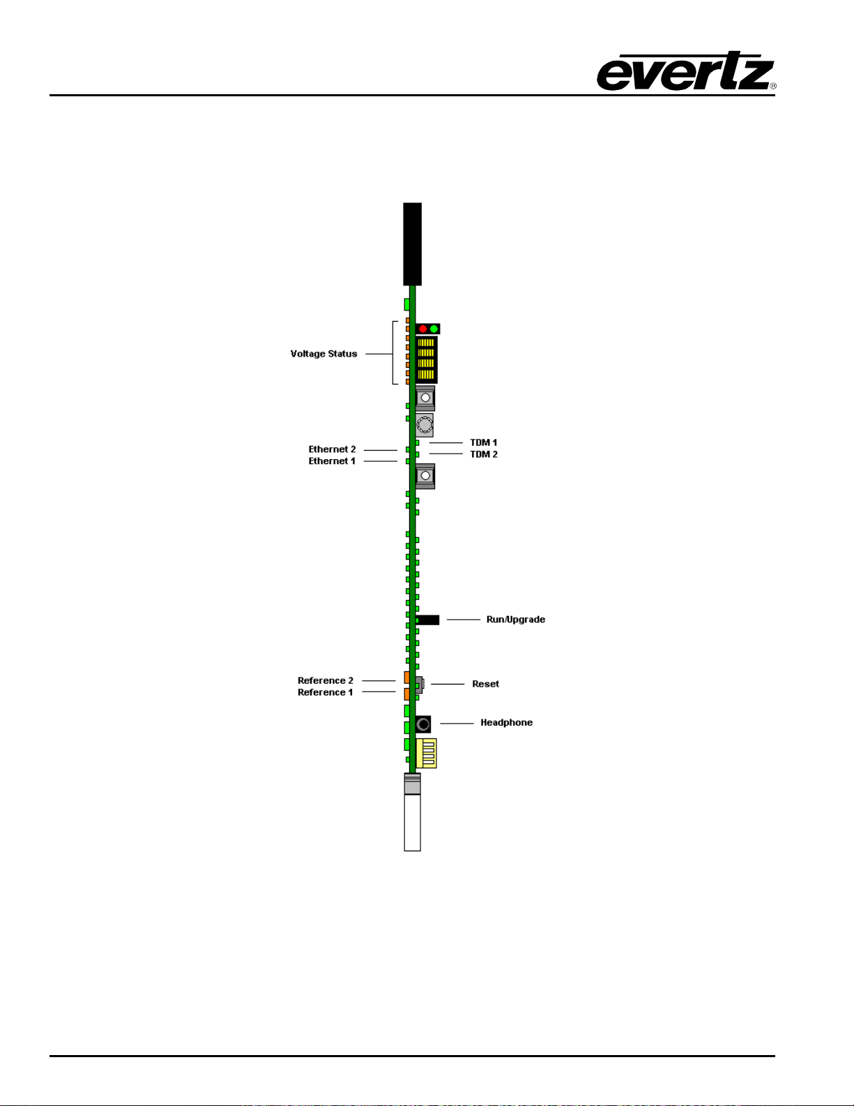
EMR User's Guide
High Density Modular Audio Router (AES, Analog, MADI, TimeCode, Data)
The EMR-PR48 front card edge has some key controls and indicators that can help in the installation and
debugging processes. Figure
behavior of each component. If the status indicators do not behave as described it can be a sign of
installation or configuration issues.
2-35 and Table 2-22 show the card edge and describe the expected
Figure
2-35: EMR-PR48 Front Card Edge
Page 62 Revision 1.8 COMPONENT OVERVIEW
Page 77
EMR User's Guide
High Density Modular Audio Router (AES, Analog, MADI, TimeCode, Data)
Component Description
Voltage Status
LEDs
Ethernet 1 LED
Ethernet 2 LED
TDM 1
TDM 2
Run/Upgrade
Jumper
Reset Button
This set of LEDs are amber in color and should always be ON
This LED is green in color and flashes when there is activity on
Ethernet port 1
This LED is green in color and flashes when there is activity on
Ethernet port 2
This LED is green in color and flashes when a valid TDM signal is
detected on TDM input 1 and is solid when it is the primary TDM
This LED is green in color and flashes when a valid TDM signal is
detected on TDM input 2 and is solid when it is the primary TDM
This jumper is used to place the module in upgrade mode when
upgrading the firmware
This button resets the module
Table 2-22: Description of EMR-PR48 Card Edge
COMPONENT OVERVIEW Revision 1.8 Page 63
Page 78
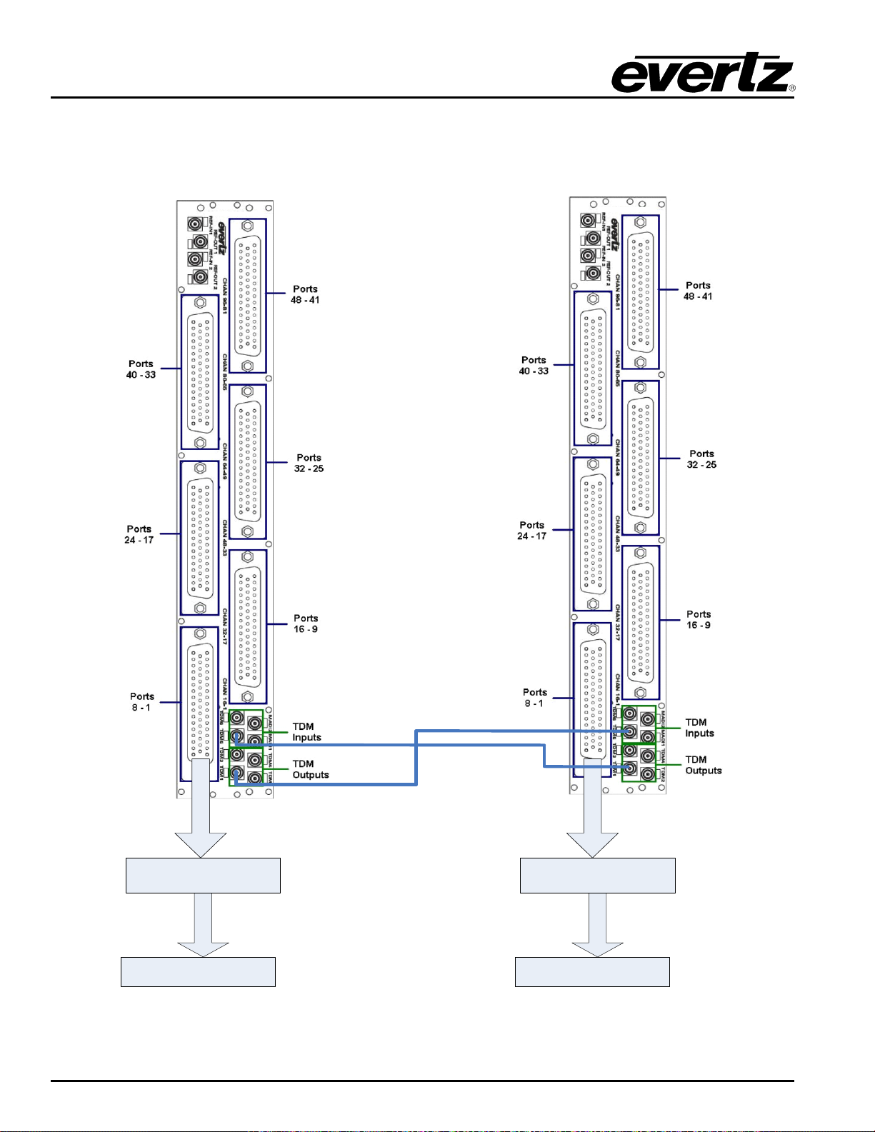
EMR User's Guide
RP-3000APR-DB50
EMR-PR48 Rear Plate EMR-PR48 Rear Plate
DB – 50
RP-3000APR-DB50
DB – 50
VTR 9-16
Patch Panel
VTR 1-8
Patch Panel
High Density Modular Audio Router (AES, Analog, MADI, TimeCode, Data)
Figure
2-36: Basic 2x EMR Port Router Setup
Page 64 Revision 1.8 COMPONENT OVERVIEW
Page 79

EMR User's Guide
High Density Modular Audio Router (AES, Analog, MADI, TimeCode, Data)
2.2.11. EMR-PR48-A Data Module
The EMR-PR48-A is a data port router card for the EMR. Each of the 48 data ports available on the
module can be configured to support either RS-442 or RS-232 serial protocols.
Each port consists of 2 reconfigurable transceivers allowing the port router to transmit or receive on each
of the Tx/Rx (sub port) connections. When the port is set at as Controller, sub port A (pins 34/18 for port 1)
is configured as a transmitter and sub port B (pins 2/19 for port 1) as a receiver, setting the port as a Slave
reverses the directions.
The EMR-PR48-A rear panel occupies 2 slots in a frame and uses 50-pin D-Sub female connectors as
shown in Figure
each connector is shown in Table
Before installing the EMR-PR48-A, some consideration should be given to the cabling to ensure that
different VTR’s and RS-422 devices will be supported correctly. Figure
allocated in a typical application.
In this example, all the EMR-PR48-A ports are wired in exactly the same way. Any Tx/Rx swaps that are
required to support controlling (edit controller) or slave (VTR) devices is defined by the VL-Pro
configuration.
Notes about serial wiring to the EMR-PR48-A:
1. The use of DB9 patch panels is optional but it is recommended that you use a consistent signal
connection scheme to allow any pair of devices to be patched together.
2. RS-422 connections should be made using screened dual twisted pair cabling. Short runs of ribbon
cabling (<3m) can be supported, longer runs may affect the advanced features of the card.
3. A GND reference connection must be provided in the cable between the EMR-PR48-A and the
remote device.
4. If the external device supports the Sony pin 5 modes then the device’s Sony pin must be wired to
the EMR-PR48-A.
2-37. Each connector supports 8 serial data ports (RS-232 or RS-422). The pin out for
2-23.
2-37 shows the first 8 ports
2.2.11.1. Learn Modes
The E MR-PR48-A has features to aid the user in establishing serial link connectivity quickly.
Learn Activity Mode: This can be used with the port standard set to RS-232 or RS-422. In this mode the
EMR-PR48-A listens f or activity on both of the sub ports in order to find out which sub port is receiving
data. The user will need to cause the connected device to send data in order for this mode to function.
Single or Multiple ports may be learned at the same time.
Learn Driver Mode: This mode is only supported with standard set to RS-422. In this mode the EMRPR48-A interrogates the 2 sub ports to find out which one is connected to the external driver. No data
activity is required on the links but the external driver must be active. It is important that the receiver port
connections are not reversed so if the ports polarity is incorrect then a warning message is shown.
Depending upon the amount of data present on the link, the mode may fail to detect properly. It is usually
sufficient to just repeat the learn request.
COMPONENT OVERVIEW Revision 1.8 Page 65
Page 80

EMR User's Guide
Note: Ensure that the GND reference connection between the external device and the
High Density Modular Audio Router (AES, Analog, MADI, TimeCode, Data)
Using the Learn Modes: The learn modes can be instigated from either VLPro or the serial menu; the
following description is when the serial menu is being used. The user has the option to learn a single port
or multiple port configurations using either of the two modes described earlier. Upon successful detection
of the ports configuration the user can accept the setting as a manual setting i.e. hard code the port as a
Controller or Slave; enter‘s’ to allow the setting to be used in the Sony mode (senses the state of the Sony
pin and port configuration together and configures the Sony operational mode based upon the sensed
conditions); or enter ‘o’ to configure the port to use the ‘order of takes direction control’ mode based upon
the sensed conditions.
2.2.11.2. Special Modes
Normally the user will just hard configure the port as a Controller or a Slave depending on how the sub
ports are connected to the TX and Rx. However, there are times where the port connections swap in use,
e.g. when EMR-PR48-A is in a system that requires machine to machine (VTR) dubbing. EMR-PR48-A
provides the following modes:
Sony Mode: This mode is only supported when the standard is set to RS422. In this mode, the status of
the external devices Sony pin (pin 5 on a 9 way ‘D’ type connector) is used to control the ports mode, i.e.
in Sony 0 = Controller, if the Sony pin is low EMR-PR48-A port will be configured as a controller, if the pin
is high then it will be configured as a slave.
Note that some VTR’s such as the Sony DVW-A500P and the Sony DNW-A75 do not support pin 5 fully
and therefore cannot be supported using the Sony modes on the EMR-PR48-A. Also note that other
VTR’s such as the Sony SRW-5500 and SRW-5800 swap the Tx/Rx pairs momentarily when the ‘Player’
button is pressed and require the Slave VTR to respond to latch the TX/RX swap and allow the controlling
VTR to control the slave device.
Default & Non-Default Mode: The EMR-PR48-A can be globally configured for one of two modes.
Default mode and Non-Default mode. In default mode: For instance if the user wants to route port 4 to 5,
user would just set the route “4” then “5” in the route menu to get a two-way traf fic. But in Non-Default
mode customer would need to set two routes “4” to “5” and then “5” to “4” to get a two-way traffic. User
won’t be able to do the normal routing when the router is in “Non-Default mode”.
Note: It will affect all the ports on the card when the card config is changed to NonDefault Mode from Default Mode
Auto 3 Detection Mode: This mode is provided to support the problematic devices mentioned above. It
continuously monitors the ports status and automatically detects when an external device swaps its Tx
and Rx connections and reconfigures the EMR-PR48-A ports accordingly. This mode should be used only
if the Sony mode does not function. This mode supports the Sony DVW-A500P, the Sony DNW-A75, the
Sony SRW-5500 and the SRW-5800 devices.
Note that this mode causes a small interruption to the transmitted data unless data is flowing on the link,
which is true for all VTRs. Therefore caution must be observed when using it on links that do not have
continuous data flowing. The Auto 3 timeout is defaulted to correctly support VTR operation.
EMR-PR48-A is made.
Page 66 Revision 1.8 COMPONENT OVERVIEW
Page 81
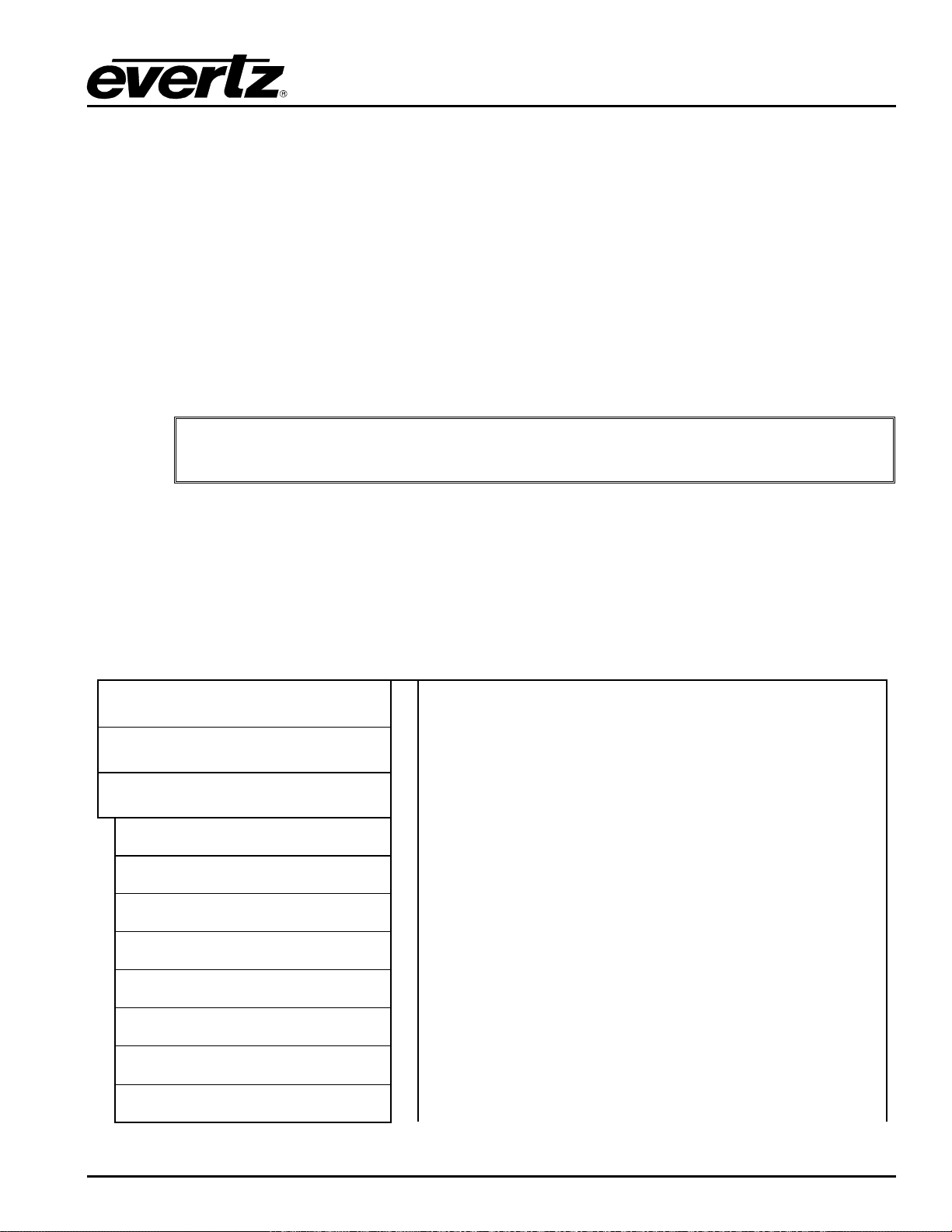
EMR User's Guide
Set X to Y Route
View/Conf Port
View/Conf Port Status
View / Configure Video Reference
View / Configure Advanced Global
View / Configure PLink Status
View Board Info
High Density Modular Audio Router (AES, Analog, MADI, TimeCode, Data)
Order of Take Controls the Direction Mode (ORDMM): Some devices i.e. VTRs change the pins used
for TX and RX depending upon their operational mode. This mode allows the user to control the PR48-A
port configuration based upon the order of the route is made.
The user can either manually select the Order of Route Determined Direction mode or work out the
controller/slave arrangement required or use the learn mode and enter ‘o’ when presented with the results
to place the port in the correct configuration in the Route Determined Direction mode.
Once configured with, for example, port 1 routed to port 5 and with port 5 set in Route Determined
Direction mode, then if port 5 is routed to port 1 then the Tx and Rx signals will swap on port 5. In other
words, which ever device is selected first becomes the controller and the device that is selected second
will become the slave.
This mode can be used when neither the Auto 3 nor the Sony modes correctly handle the device i.e. VTR.
Note: An EMR-PR48-A module has 48 ports to configure. Once this is completed you
should save the settings in VL-Pro for later recall.
2.2.11.3. Configuration and Monitoring Menu
EMR-PR48-A contains configuration and monitoring menu that allows the user to change some internal
settings of the device and also to monitor various components on the card.
The configuration and monitoring menu can be accessed using either Telnet session or serial connection.
Once gained access to the main menu, use the numbers beside the items to set the value. Follow the on
screen instructions to set the value of the parameter, save and exit the configuration.
Network Configuration
SNMP Configuration
Port Configuration
View Port Routing Table
Status - Individual Port
- All Ports
Configuration of Network 1 and 2
Configuration of Simple Network Management Protocol.
Views Route Table
Sets individual route
View and mode configuration of individual port
View and mode configuration of all ports
COMPONENT OVERVIEW Revision 1.8 Page 67
View and configuration of Video reference
Accessed by Evertz technical support staff only
View and configuration of Plink and ADMX mode
Views board information
Page 82
EMR User's Guide
High Density Modular Audio Router (AES, Analog, MADI, TimeCode, Data)
Trace - Engineering Only
Engineering Debug Utilit y
2.2.11.4. Status Signal Polarity: When the standard is set to RS-422 the EMR-PR48-A advises the user of the state of the Rx
signals polarity (i.e. swapped +ve/-ve signal lines).
Data Activity: Any activity on the EMR-PR48-A receivers is provided to the user on both the status
display and the 24 front LEDs (2 LEDs per port, one for each of the sub ports).
Baud Rate: Provided there is sufficient activity on the receiver port, the EMR-PR48-A will sho w the link s
baud rate. This is updated every 8s.
Auto/Sony State: When operating the port in Auto 3 Detection mode or the Sony mode, the state of the
port mode/Sony pin status is shown.
Port Routing: Shows the interconnections (routes) between the ports.
Note: Setting the route to 337 will route Null to the port (i.e. the port o/p will be in the
idle state). Setting the route to the same number as the port will route the port input
to its output.
Accessed by Evertz technical support staff only
Accessed by Evertz technical support staff only
2.2.11.5. Data Port D50 Connector – Pin Out
The E MR-PR48-A uses female D50 connectors, with each connector carrying 8 data ports. The details of
how each of the D50 pins map to each of the 8 ports is shown in Figure
2-37.
Page 68 Revision 1.8 COMPONENT OVERVIEW
Page 83
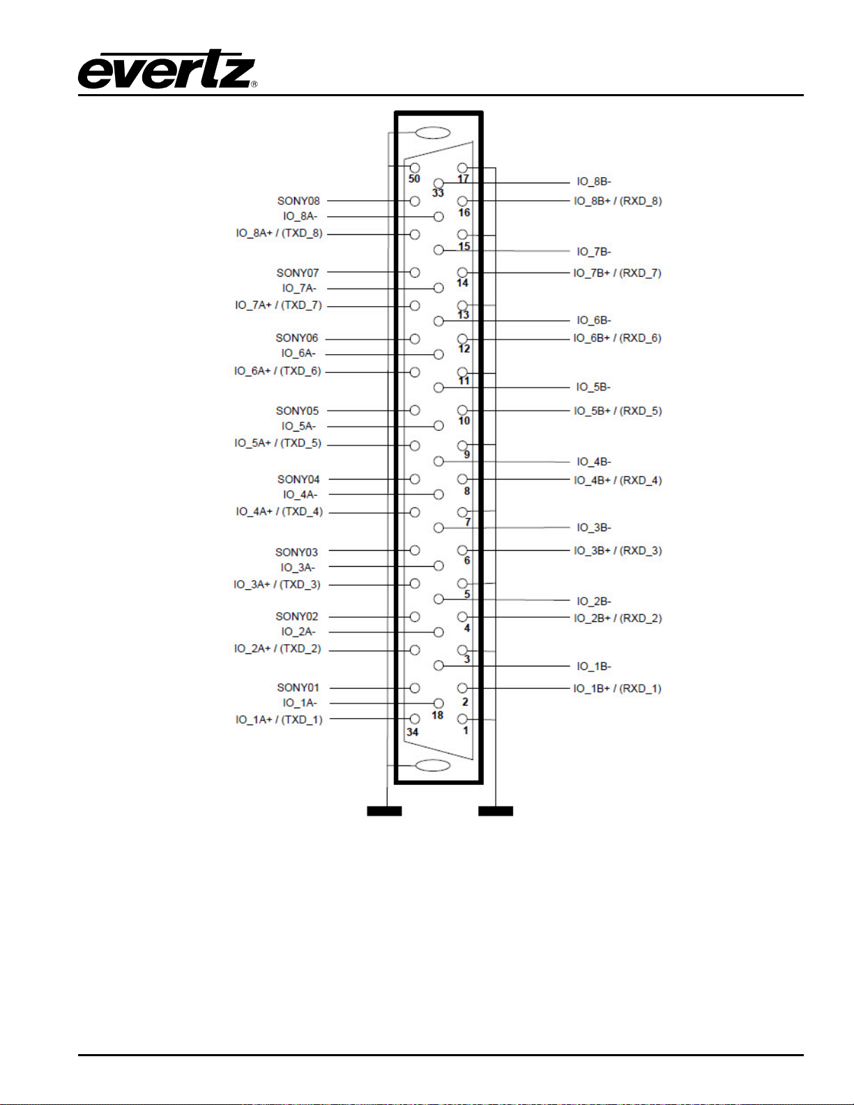
EMR User's Guide
High Density Modular Audio Router (AES, Analog, MADI, TimeCode, Data)
Figure
2-37: Data Port D50 Connector – Pin Out
The pins on each port can vary depending on whether the port is configured for RS-232 or RS-422 and
whether the port is configured as a controller or a slave. Depending on these configuration parameters,
the pin-outs for each port are different.
COMPONENT OVERVIEW Revision 1.8 Page 69
Page 84
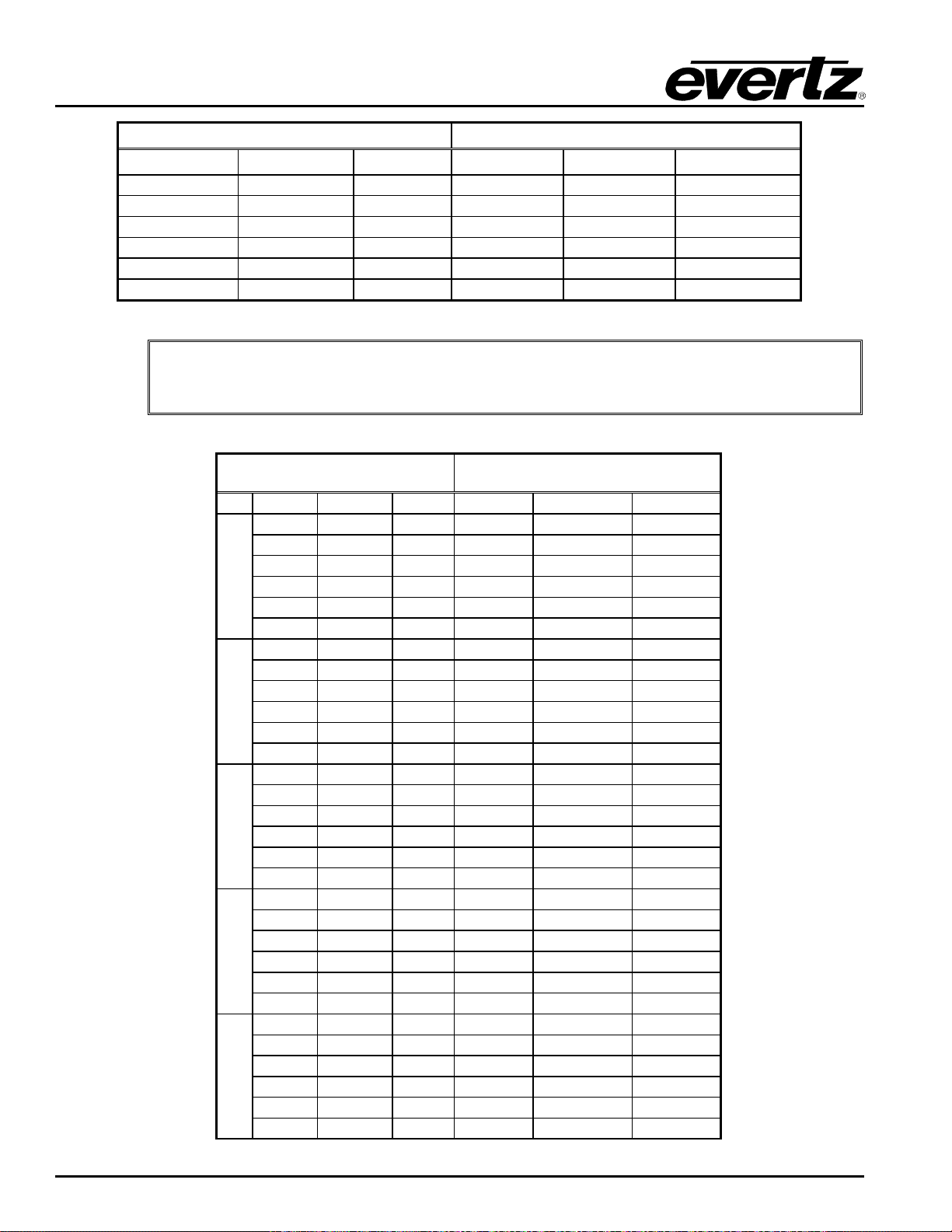
EMR User's Guide
Controller
Slave
RS-422
RS-232
D9 Pin
RS-422
RS-232
D9 Pin
Rx+
RXD
3
Tx+
TXD
7
Rx-
8 Tx- 2
Tx+
TXD
7
Rx+
RXD
3
Tx-
2 Rx- 8
Sony
5 Sony 5
0V ( GND)
0V ( GND)
4&6
0V ( GND)
0V ( GND)
4&6
CTRL
SLAVE
D50
RS422
RS232
D9
Rx+
Tx+
2
Tx+
TXD
Pin 3
Rx-
Tx-
19
Tx-
Pin 8
Tx+
Tx+
34
Rx+
RXD
Pin 7
Tx-
Tx-
18
Rx-
Pin 2
Sony
Sony
35
Sony
Pin 5
0v
0v 1 0v
0v
Pin 4 & 6
Rx+
Tx+
4
Tx+
TXD
Pin 3
Rx-
Tx-
21
Tx-
Pin 8
Tx+
Tx+
36
Rx+
RXD
Pin 7
Tx-
Tx-
20
Rx-
Pin 2
Sony
Sony
37
Sony
Pin 5
0v
0v 3 0v
0v
Pin 4 & 6
Rx+
Tx+
6
Tx+
TXD
Pin 3
Rx-
Tx-
23
Tx-
Pin 8
Tx+
Tx+
38
Rx+
RXD
Pin 7
Tx-
Tx-
22
Rx-
Pin 2
Sony
Sony
39
Sony
Pin 5
0v
0v 5 0v
0v
Pin 4 & 6
Rx+
Tx+
8
Tx+
TXD
Pin 3
Rx-
Tx-
25
Tx-
Pin 8
Tx+
Tx+
40
Rx+
RXD
Pin 7
Tx-
Tx-
24
Rx-
Pin 2
Sony
Sony
41
Sony
Pin 5
0v
0v 7 0v
0v
Pin 4 & 6
Rx+
Tx+
10
Tx+
TXD
Pin 3
Rx-
Tx-
27
Tx-
Pin 8
Tx+
Tx+
42
Rx+
RXD
Pin 7
Tx-
Tx-
26
Rx-
Pin 2
Sony
Sony
43
Sony
Pin 5
0v
0v 9 0v
0v
Pin 4 & 6
High Density Modular Audio Router (AES, Analog, MADI, TimeCode, Data)
Table 2-23: External Device Standard Controller and Slave D9 Pinouts
Note: Some VTRs use signal names TxA and TxB. On the EMR-PR48-A TX+ is TxB
and TX- is TxA.
PR48-A Port Mode Remote Unit
1
2
3
4
Page 70 Revision 1.8 COMPONENT OVERVIEW
5
Page 85
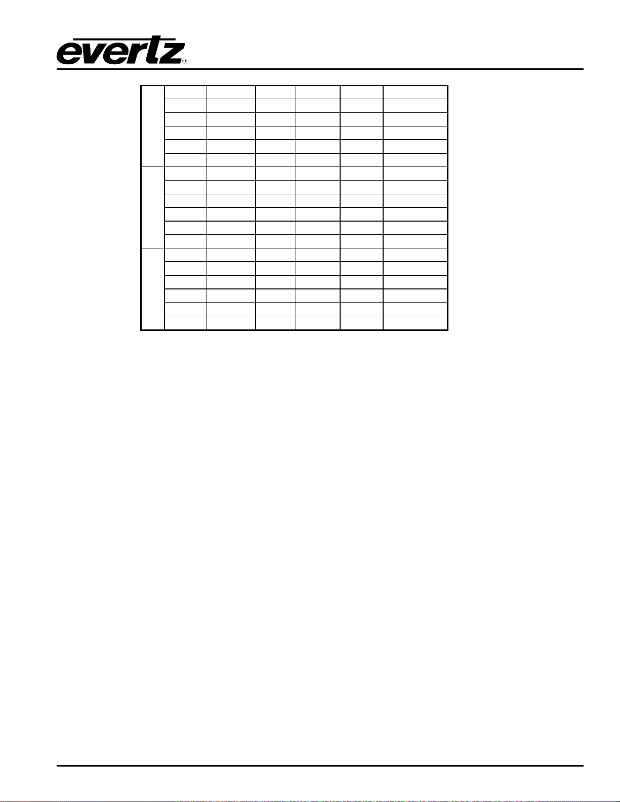
EMR User's Guide
Rx+
Tx+
12
Tx+
TXD
Pin 3
Rx-
Tx-
29
Tx- Pin 8
Tx+
Tx+
44
Rx+
RXD
Pin 7
Tx-
Tx-
28
Rx- Pin 2
Sony
Sony
45
Sony Pin 5
0v
0v
11
0v
0v
Pin 4 & 6
Rx+
Tx+
14
Tx+
TXD
Pin 3
Rx-
Tx-
31
Tx- Pin 8
Tx+
Tx+
46
Rx+
RXD
Pin 7
Tx-
Tx-
30
Rx- Pin 2
Sony
Sony
47
Sony Pin 5
0v
0v
13
0v
0v
Pin 4 & 6
Rx+
Tx+
16
Tx+
TXD
Pin 3
Rx-
Tx-
33
Tx- Pin 8
Tx+
Tx+
48
Rx+
RXD
Pin 7
Tx-
Tx-
32
Rx- Pin 2
Sony
Sony
49
Sony Pin 5
0v
0v
15
0v
0v
Pin 4 & 6
High Density Modular Audio Router (AES, Analog, MADI, TimeCode, Data)
6
7
8
Table
2-24: Recommended Port Wiring
COMPONENT OVERVIEW Revision 1.8 Page 71
Page 86
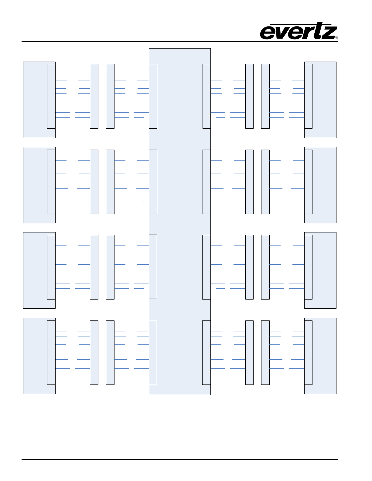
EMR User's Guide
Controller 1
3
8
7
2
5
4
6
3
8
7
2
5
4
6
Ctl Tx+
Ctl Tx-
Ctl Rx+
Ctl Rx-
Pin 5
0V
0V
3
8
7
2
5
4
6
Ctl Tx+
Ctl Tx-
Ctl Rx+
Ctl Rx-
Pin 5
0V
0V
EMR-PR48
2
19
34
18
35
1
4
21
36
20
37
3
3
8
7
2
5
4
6
3
8
7
2
5
4
6
Ctl Tx+
Ctl Tx-
Ctl Rx+
Ctl Rx-
Pin 5
0V
0V
Ctl Tx+
Ctl Tx-
Ctl Rx+
Ctl Rx-
Pin 5
0V
0V
Port 1
Controller
Port 5
Slave
VTR 2
3
8
7
2
5
4
6
Rx
Tx
Rx
Tx
Tx
Rx
10
27
42
26
43
9
3
8
7
2
5
4
6
3
8
7
2
5
4
6
Ctl Tx+
Ctl Tx-
Ctl Rx+
Ctl Rx-
Pin 5
0V
0V
Ctl Tx+
Ctl Tx-
Ctl Rx+
Ctl Rx-
Pin 5
0V
0V
Port 6
Slave
VTR 3
3
8
7
2
5
4
6
Rx
Tx
Tx
Rx
Optional D9
Patch Panel
Optional D9
Patch Panel
Controller 2
3
8
7
2
5
4
6
3
8
7
2
5
4
6
Ctl Tx+
Ctl Tx-
Ctl Rx+
Ctl Rx-
Pin 5
0V
0V
3
8
7
2
5
4
6
Ctl Tx+
Ctl Tx-
Ctl Rx+
Ctl Rx-
Pin 5
0V
0V
12
29
44
28
45
11
Port 2
Controller
Rx
Tx
Optional D9
Patch Panel
Controller 3
3
8
7
2
5
4
6
3
8
7
2
5
4
6
Ctl Tx+
Ctl Tx-
Ctl Rx+
Ctl Rx-
Pin 5
0V
0V
3
8
7
2
5
4
6
Ctl Tx+
Ctl Tx-
Ctl Rx+
Ctl Rx-
Pin 5
0V
0V
3
8
7
2
5
4
6
3
8
7
2
5
4
6
Ctl Tx+
Ctl Tx-
Ctl Rx+
Ctl Rx-
Pin 5
0V
0V
Ctl Tx+
Ctl Tx-
Ctl Rx+
Ctl Rx-
Pin 5
0V
0V
Port 3
Controller
Port 7
Slave
VTR 4
3
8
7
2
5
4
6
Rx
Tx
Rx
Tx
Tx
Rx
14
31
46
30
47
13
3
8
7
2
5
4
6
3
8
7
2
5
4
6
Ctl Tx+
Ctl Tx-
Ctl Rx+
Ctl Rx-
Pin 5
0V
0V
Ctl Tx+
Ctl Tx-
Ctl Rx+
Ctl Rx-
Pin 5
0V
0V
Port 8
Slave
VTR 5
3
8
7
2
5
4
6
Rx
Tx
Tx
Rx
Optional D9
Patch Panel
Optional D9
Patch Panel
VTR 1
3
8
7
2
5
4
6
3
8
7
2
5
4
6
Ctl Tx+
Ctl Tx-
Ctl Rx+
Ctl Rx-
Pin 5
0V
0V
3
8
7
2
5
4
6
Ctl Tx+
Ctl Tx-
Ctl Rx+
Ctl Rx-
Pin 5
0V
0V
16
33
48
32
49
15
Port 4
Controller
Rx
Tx
Optional D9
Patch Panel
6
23
38
22
39
5
8
25
40
24
41
7
Rx
Tx
Rx
Tx
Rx
Tx
Rx
Tx
High Density Modular Audio Router (AES, Analog, MADI, TimeCode, Data)
Figure
2-38: Example System Connections
Page 72 Revision 1.8 COMPONENT OVERVIEW
Page 87
EMR User's Guide
Note: A video black and burst reference signal must be connected to the frame when
Input Card
Connector
From
Output Card
Connector
Card 1 In 1
TDM 5
Card 2 Out 1
TDM 1
Card 2 In 1
TDM 5
Card 1 Out 1
TDM 1
Card 1 In 1
TDM 5
Card 2 Out 1
TDM 1
Card 1 In 2
TDM 6
Card 3 Out 1
TDM 1
Card 2 In 1
TDM 5
Card 1 Out 1
TDM 1
Card 2 In 2
TDM 6
Card 3 Out 2
TDM 3
Card 3 In 1
TDM 5
Card 1 Out 2
TDM 3
Card 3 In 2
TDM 6
Card 2 Out 2
TDM 3
Card 1 In 1
TDM 5
Card 2 Out 1
TDM 1
Card 1 In 2
TDM 6
Card 3 Out 1
TDM 1
Card 1 In 3
MADI 1
Card 4 Out 1
TDM 1
Card 2 In 1
TDM 5
Card 1 Out 1
TDM 1
Card 2 In 2
TDM 6
Card 3 Out 2
TDM 3
Card 2 In 3
MADI 1
Card 4 Out 2
TDM 3
Card 3 In 1
TDM 5
Card 1 Out 2
TDM 3
Card 3 In 2
TDM 6
Card 2 Out 2
TDM 3
Card 3 In 3
MADI 1
Card 4 Out 3
TDM 2
Card 4 In 1
TDM 5
Card 1 Out 3
TDM 2
Card 4 In 2
TDM 6
Card 2 Out 3
TDM 2
Card 4 In 3
MADI 1
Card 3 Out 3
TDM 2
High Density Modular Audio Router (AES, Analog, MADI, TimeCode, Data)
2.2.11.6. Multicard Systems
The EMR-PR48-A rear plate has 6 TDM outputs and 6 TDM inputs via DIN 1.0/2.3 connectors. These
connectors allow for further port expansion. The EMR-PR48-A can expand to a system of 336 ports
without the need for an ADMX cross point. In a Multicard system, port 1 can be routed to any of the 336
outputs. Details of the expansion are shown in Section 4.2.1.
expanding a system beyond a single module.
Table 2-25: Multi-Card TDM Cables (96 Ports, 2 Card Systems)
Input Card Connector From Output Card Connector
Table 2-26: Multi-Card TDM Cables (144 Ports, 3 Card Systems)
Input Card Connector From Output Card Connector
Table 2-27: Multi-Card TDM Cables (192 Ports, 4 Card Systems)
COMPONENT OVERVIEW Revision 1.8 Page 73
Page 88
EMR User's Guide
Card 1 In 1
TDM 5
Card 2 Out 1
TDM 1
Card 1 In 2
TDM 6
Card 3 Out 1
TDM 1
Card 1 In 3
MADI 1
Card 4 Out 1
TDM 1
Card 1 In 4
MADI 2
Card 5 Out 1
TDM 1
Card 2 In 1
TDM 5
Card 1 Out 1
TDM 1
Card 2 In 2
TDM 6
Card 3 Out 2
TDM 3
Card 2 In 3
MADI 1
Card 4 Out 2
TDM 3
Card 2 In 4
MADI 2
Card 5 Out 2
TDM 3
Card 3 In 1
TDM 5
Card 1 Out 2
TDM 3
Card 3 In 2
TDM 6
Card 2 Out 2
TDM 3
Card 3 In 3
MADI 1
Card 4 Out 3
TDM 2
Card 3 In 4
MADI 2
Card 5 Out 3
TDM 2
Card 4 In 1
TDM 5
Card 1 Out 3
TDM 2
Card 4 In 2
TDM 6
Card 2 Out 3
TDM 2
Card 4 In 3
MADI 1
Card 3 Out 3
TDM 2
Card 4 In 4
MADI 2
Card 5 Out 4
TDM 4
Card 5 In 1
TDM 5
Card 1 Out 4
TDM 4
Card 5 In 2
TDM 6
Card 2 Out 4
TDM 4
Card 5 In 3
MADI 1
Card 3 Out 4
TDM 4
Card 5 In 4
MADI 2
Card 4 Out 4
TDM 4
High Density Modular Audio Router (AES, Analog, MADI, TimeCode, Data)
Input Card Connector From Output Card Connector
Table 2-28: Multi-Card TDM Cables (240 Ports, 5 Card Systems)
Page 74 Revision 1.8 COMPONENT OVERVIEW
Page 89
EMR User's Guide
Card 1 In 1
TDM 5
Card 2 Out 1
TDM 1
Card 1 In 2
TDM 6
Card 3 Out 1
TDM 1
Card 1 In 3
MADI 1
Card 4 Out 1
TDM 1
Card 1 In 4
MADI 2
Card 5 Out 1
TDM 1
Card 1 In 5
REF_IN 2
Card 6 Out 1
TDM 1
Card 2 In 1
TDM 5
Card 1 Out 1
TDM 1
Card 2 In 2
TDM 6
Card 3 Out 2
TDM 3
Card 2 In 3
MADI 1
Card 4 Out 2
TDM 3
Card 2 In 4
MADI 2
Card 5 Out 2
TDM 3
Card 2 In 5
REF_IN 2
Card 6 Out 2
TDM 3
Card 3 In 1
TDM 5
Card 1 Out 2
TDM 3
Card 3 In 2
TDM 6
Card 2 Out 2
TDM 3
Card 3 In 3
MADI 1
Card 4 Out 3
TDM 2
Card 3 In 4
MADI 2
Card 5 Out 3
TDM 2
Card 3 In 5
REF_IN 2
Card 6 Out 3
TDM 2
Card 4 In 1
TDM 5
Card 1 Out 3
TDM 2
Card 4 In 2
TDM 6
Card 2 Out 3
TDM 2
Card 4 In 3
MADI 1
Card 3 Out 3
TDM 2
Card 4 In 4
MADI 2
Card 5 Out 4
TDM 4
Card 4 In 5
REF_IN 2
Card 6 Out 4
TDM 4
Card 5 In 1
TDM 5
Card 1 Out 4
TDM 4
Card 5 In 2
TDM 6
Card 2 Out 4
TDM 4
Card 5 In 3
MADI 1
Card 3 Out 4
TDM 4
Card 5 In 4
MADI 2
Card 4 Out 4
TDM 4
Card 5 In 5
REF_IN 2
Card 6 Out 5
REF_OUT_2
Card 6 In 1
TDM 5
Card 1 Out 5
REF_OUT_2
Card 6 In 2
TDM 6
Card 2 Out 5
REF_OUT_2
Card 6 In 3
MADI 1
Card 3 Out 5
REF_OUT_2
Card 6 In 4
MADI 2
Card 4 Out 5
REF_OUT_2
Card 6 In 5
REF_IN 2
Card 5 Out 5
REF_OUT_2
High Density Modular Audio Router (AES, Analog, MADI, TimeCode, Data)
Input Card Connector From Output Card Connector
COMPONENT OVERVIEW Revision 1.8 Page 75
Table 2-29: Multi-Card TDM Cables (288 Ports, 6 Card Systems)
Page 90

EMR User's Guide
Input Card
Connector
From
Output Card
Connector
Card 1 In 1
TDM 5
Card 2 Out 1
TDM 1
Card 1 In 2
TDM 6
Card 3 Out 1
TDM 1
Card 1 In 3
MADI 1
Card 4 Out 1
TDM 1
Card 1 In 4
MADI 2
Card 5 Out 1
TDM 1
Card 1 In 5
REF_IN 2
Card 6 Out 1
TDM 1
Card 1 In 6
REF_IN 1
Card 7 Out 1
TDM 1
Card 2 In 1
TDM 5
Card 1 Out 1
TDM 1
Card 2 In 2
TDM 6
Card 3 Out 2
TDM 3
Card 2 In 3
MADI 1
Card 4 Out 2
TDM 3
Card 2 In 4
MADI 2
Card 5 Out 2
TDM 3
Card 2 In 5
REF_IN 2
Card 6 Out 2
TDM 3
Card 2 In 6
REF_IN 1
Card 7 Out 2
TDM 3
Card 3 In 1
TDM 5
Card 1 Out 2
TDM 3
Card 3 In 2
TDM 6
Card 2 Out 2
TDM 3
Card 3 In 3
MADI 1
Card 4 Out 3
TDM 2
Card 3 In 4
MADI 2
Card 5 Out 3
TDM 2
Card 3 In 5
REF_IN 2
Card 6 Out 3
TDM 2
Card 3 In 6
REF_IN 1
Card 7 Out 2
TDM 2
Card 4 In 1
TDM 5
Card 1 Out 3
TDM 2
Card 4 In 2
TDM 6
Card 2 Out 3
TDM 2
Card 4 In 3
MADI 1
Card 3 Out 3
TDM 2
Card 4 In 4
MADI 2
Card 5 Out 4
TDM 4
Card 4 In 5
REF_IN 2
Card 6 Out 4
TDM 4
Card 4 In 6
REF_IN 1
Card 7 Out 4
TDM 4
Card 5 In 1
TDM 5
Card 1 Out 4
TDM 4
Card 5 In 2
TDM 6
Card 2 Out 4
TDM 4
Card 5 In 3
MADI 1
Card 3 Out 4
TDM 4
Card 5 In 4
MADI 2
Card 4 Out 4
TDM 4
Card 5 In 5
REF_IN 2
Card 6 Out 5
REF_OUT_2
Card 5 In 6
REF_IN 1
Card 7 Out 5
REF_OUT_2
Card 6 In 1
TDM 5
Card 1 Out 5
REF_OUT_2
Card 6 In 2
TDM 6
Card 2 Out 5
REF_OUT_2
Card 6 In 3
MADI 1
Card 3 Out 5
REF_OUT_2
Card 6 In 4
MADI 2
Card 4 Out 5
REF_OUT_2
Card 6 In 5
REF_IN 2
Card 5 Out 5
REF_OUT_2
Card 6 In 6
REF_IN 1
Card 7 Out 6
REF_OUT_1
Card 7 In 1
TDM 5
Card 1 Out 6
REF_OUT_1
Card 7 In 2
TDM 6
Card 2 Out 6
REF_OUT_1
Card 7 In 3
MADI 1
Card 3 Out 6
REF_OUT_1
Card 7 In 4
MADI 2
Card 4 Out 6
REF_OUT_1
Card 7 In 5
REF_IN 2
Card 5 Out 6
REF_OUT_1
Card 7 In 6
REF_IN 1
Card 6 Out 6
REF_OUT_1
High Density Modular Audio Router (AES, Analog, MADI, TimeCode, Data)
Table 2-30: Multi-Card TDM Cables (336 Ports, 7 Card Systems)
Page 76 Revision 1.8 COMPONENT OVERVIEW
Page 91
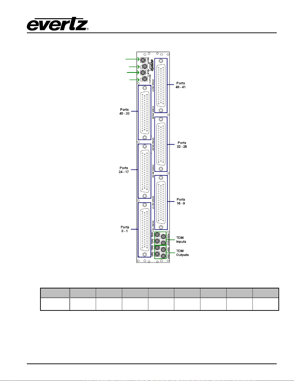
EMR User's Guide
RP-3000APR-DB50
TDM IN 5
TDM IN 6
TDM OUT
5
TDM OUT 6
TDM
OUT 1
TDM
OUT 2
TDM
OUT 3
TDM
OUT 4
TDM IN
1
TDM IN
2
TDM IN
3
TDM IN
4
High Density Modular Audio Router (AES, Analog, MADI, TimeCode, Data)
Figure
2-39: EMR-PR48-A Rear Plate
Label TDM 1 TDM 3 TDM 2 TDM 4 TDM 5 TDM 6 MADI 1 MADI 2
Actual I/O
Table 2-31: EMR-PR48-A TDM Connections
COMPONENT OVERVIEW Revision 1.8 Page 77
Page 92
EMR User's Guide
This LED is amber in color and indicates the presence of a valid
it’s a valid backup reference.
This LED is amber in color and indicates the presence of a valid
it’s a valid backup reference.
High Density Modular Audio Router (AES, Analog, MADI, TimeCode, Data)
2.2.11.7. Front Card Edge Control and LEDs
The E MR-PR48-A front card edge has some key controls and indicators that can help in the installation
and debugging processes. Figure
behavior of each component. If the status indicators do not behave as described it can be a sign of
installation or configuration issues.
Component Description
2-40 and Table 2-32 show the card edge and describe the expected
Voltage Status LEDs
Ethernet 1 LED
Ethernet 2 LED
TDM 1 - 6
Bank Select Push
Button
CH 1-12 LED
CH 13-24 LED
CH 25-36 LED
CH 37-48 LED
Activity LEDs
This set of LEDs are amber in color and should always be ON
This LED is amber in color and flashes when there is activity on
Ethernet port 1
This LED is amber in color and flashes when there is activity on
Ethernet port 2
This LED is green in color when a valid TDM signal is detected on
TDM input.
Selects the bank of inputs that are being monitored by the PR
activity LEDs
This LED is green in color and indic ates that in puts 1 t o 12 are
currently being monitored by the LTC activity LEDs
This LED is green in color and indicates that inputs 13 to 24 are
currently being monitored by the LTC activity LEDs
This LED is green in color and indicates that inputs 25 to 36 are
currently being monitored by the LTC activity LEDs
This LED is green in color and indicates that inputs 37 to 48 are
currently being monitored by the LTC activity LEDs
This set of LEDs are green in color and indicate the Activity on
each respective sub port ( Left = Sub Port B, Right = Sub Port A)
Reference 1 LED
Reference 2 LED
Run/Upgrade Jumper
Reset Button
reference on input 1. It will flash (2Hz for Pal and 1Hz for NTSC) if
reference is present and is the used reference, or intermittently if
reference on input 1. It will flash (2Hz for Pal and 1Hz for NTSC) if
reference is present and is the used reference, or intermittently if
This jumper is used to place the module in upgrade mode when
upgrading the firmware
This button resets the module
Table
2-32: Description of EMR-PR48-A Card Edge
Page 78 Revision 1.8 COMPONENT OVERVIEW
Page 93
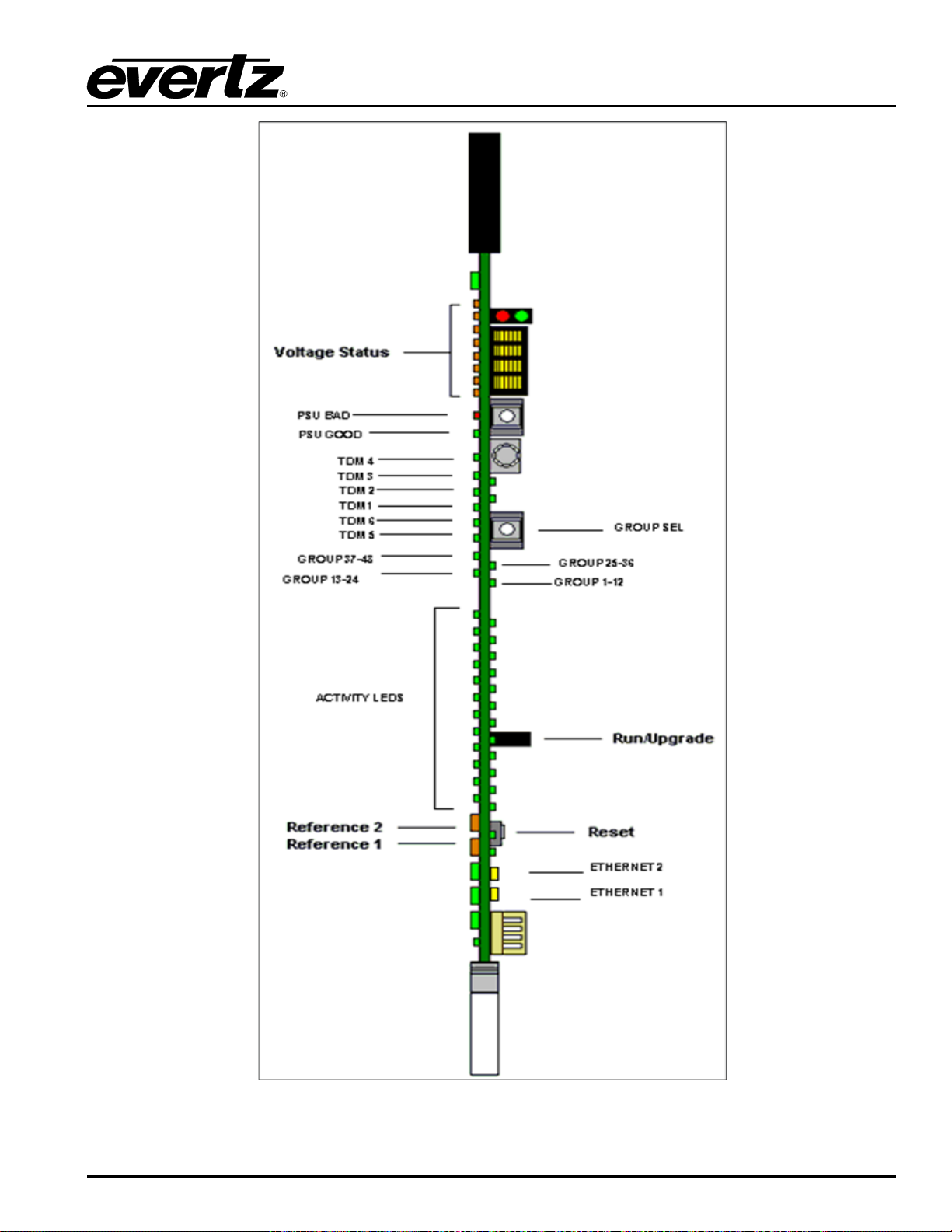
EMR User's Guide
High Density Modular Audio Router (AES, Analog, MADI, TimeCode, Data)
Figure
2-40: EMR-PR48-A Front Card Edge
COMPONENT OVERVIEW Revision 1.8 Page 79
Page 94
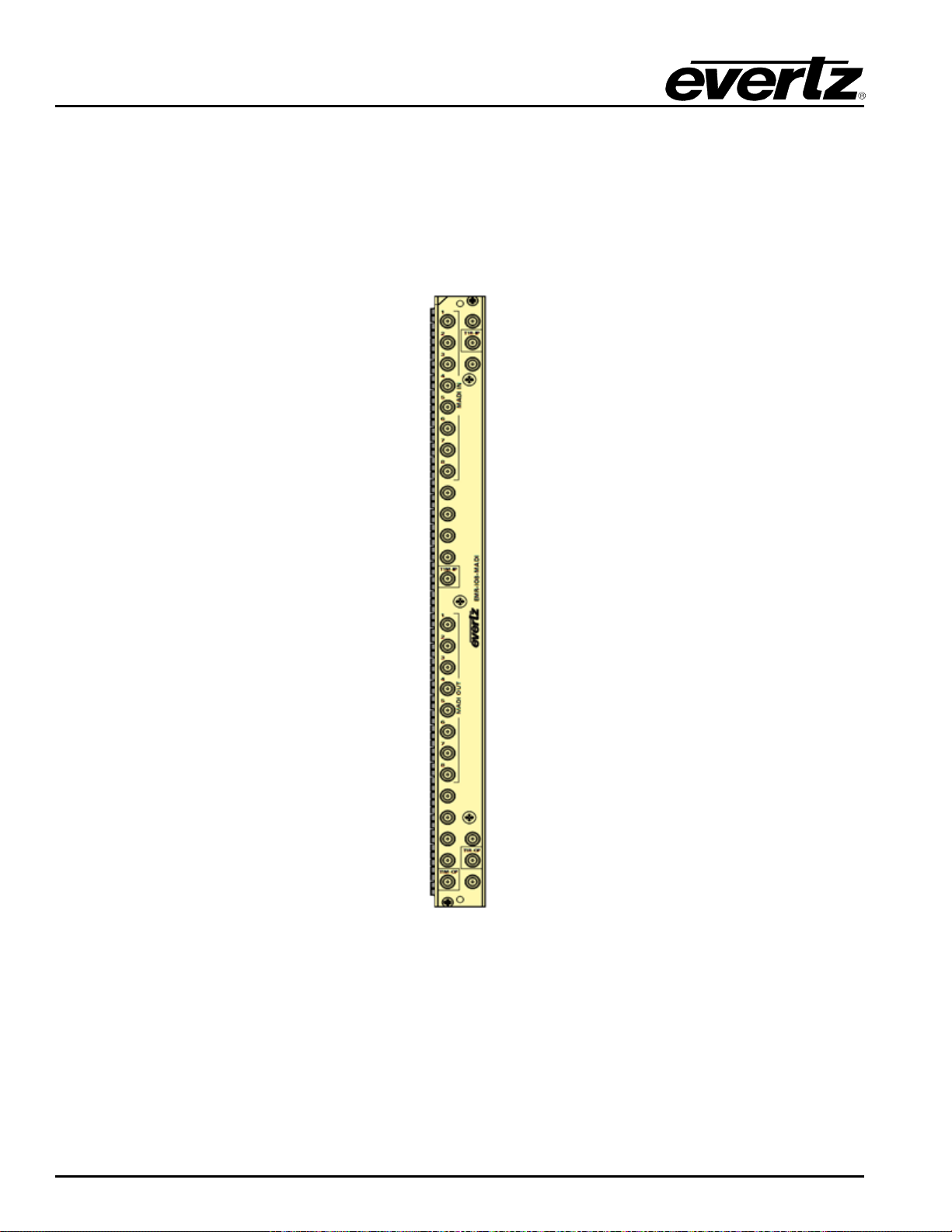
EMR User's Guide
High Density Modular Audio Router (AES, Analog, MADI, TimeCode, Data)
2.2.12. EMR-IO8-MADI
The EMR-IO8-MADI is an audio card that can support 56 or 64 channels MADI signal. It has 8 MADI
inputs mark e d as “ MAD I IN ” and 8 MADI outputs marked as “MADI OUT” on the rear plate and also has 2
TDM input and 2 TDM output ports. Each TDM input and an output port carries 640 audio channels. TDM
input and TDM output ports have Main and Redundancy. The EMR-IO8-MADI rear panel occupies 1 slot
in a frame and has DIN 1.0/2.3 connectors as shown in Figure 2-41. The connectors labeled MADI IN and
MADI OUT on the rear plate.
Figure
2-41 : EMR-IO8-MADI Rear Plate
Of the two TDM Inputs, the one which marked as “T1M-IP” is for Main and the other one which is marked
as “T1R-IP” is for Redundant on the rear plate.
Of the two TDM Outputs, the one which is marked as “T1M-OP” is for Main and the other which is marked
as “T1R-OP” is for Redundant.
The EMR-IO8-MADI supports TDM V1 and TDM V2. It also supports two network IP Addresses and
VISTALINK
Monitoring and SNMP management system.
®
The impedance is 75 Ω terminating, the power consumption is 27W and the required voltage is +12VDC.
Page 80 Revision 1.8 COMPONENT OVERVIEW
Page 95
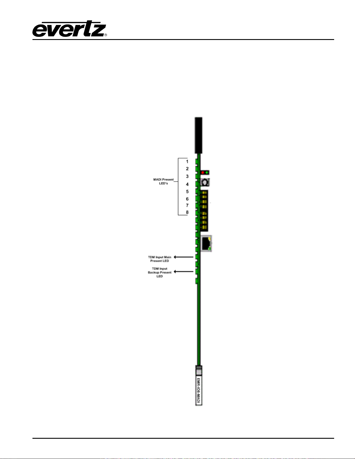
EMR User's Guide
High Density Modular Audio Router (AES, Analog, MADI, TimeCode, Data)
EMR-IO8-MADI can be used in EMX1RU, EMX3RU and EMX6RU Frames with 1 slot occupancy.
Note that the orientation of the rear plate and EMR-IO8-MADI module are different when installing on the
EMX6RU verses EMX3RU and EMX1RU frames.
Front Card Edge Controls and LEDs
The EMR-IO8-MADI front card edge has some key controls and indicators that can help in the installation
and debugging processes. Figure 2-42 and Table 2-33 shows the card e dge and describes the expected
behavior of each component.
Figure
2-42 : Front Card Edge of EMR-IO8-MADI
COMPONENT OVERVIEW Revision 1.8 Page 81
Page 96
EMR User's Guide
Component
Description
RED
No MADI Signal
Green
MADI Signal Present
OFF
No TDM Signal
BLUE
Audio Packet without LSID
GREEN
Audio Packet with LSID
AMBER
LSID with no Audio Packet
Rotary Switch
Switches the display to view firmware version, IP address A, IP address B
High Density Modular Audio Router (AES, Analog, MADI, TimeCode, Data)
MADI Present LEDs
TDM Present LEDs
Table 2-33 : Description of EMR-IO8-MADI Card Edge
2.3. INSTALLING AND REMOVING THE MODULE S
2.3.1. Installing the Module Rear Plate
In most cases, the EMR frame will already have the modules and rear plates installed within the frame.
However, when modules and rear plates need re-positioning, or when additional modules are purchased,
proper module/rear plate installation is required.
Each EMR module is shipped with a matching rear panel plate that houses the appropriate connectors for
that module.
To Install the Rear Plate:
1. Locate the specific slot in the frame and remove any filler plates.
2. Install the rear plate over the open slot by first fitting the plate then tightening the two lock-screws.
3. Fasten the third screw in the middle of the rear plate. (Only on 3000FR)
4. Tighten the screws after the main module is installed.
CAUTION: If any of the screws for the rear plate are missing, please contact
Evertz immediately for the specification and/or replacement. Using the
incorrect screw can cause thread stripping.
2.3.2. Opening and Closing the Front Panel
In order to insert or remove modules you will have to open the front panel using the following procedure:
1. Turn the two captive screws located on the front panel counter clockwise several turns until they
release completely from the front extrusions.
2. Carefully lower the front panel door so that the front edge of the door is lower than the rear of the door.
Page 82 Revision 1.8 COMPONENT OVERVIEW
Page 97

EMR User's Guide
FR have front mounted cooling fans and require the
area below them to be flush so that there is sufficient room to open the frame door
High Density Modular Audio Router (AES, Analog, MADI, TimeCode, Data)
2.3.3. Installing a Module
1. Orient the module vertically such that the smaller white card ejector is on the bottom, while the larger
black card ejector is on the top.
2. Align the card with the card guide corresponding to the slot number where you installed the rear panel
plate.
3. Carefully slide the module into the frame and press it completely into the rear panel connectors.
4. Use the upper card-ejector to latch the module into the slot.
5. Make sure that the connectors are fully seated in the rear panel.
6. When this is done, close the front panel and then tighten the screws that hold the rear panel in place.
2.3.4. Removing a Module
1. Press the card ejector down to release the module.
2. Grasp the card using the upper card ejector and pull the module out from the frame.
3. Carefully place the module in a safe place, free from static discharge.
2.4. MOUNTING
The EMR frame is equipped with rack mounting rails and fits into a standard rack space. The 3000FR
requires a 19” x 10.5” x 14.5” (483 mm x 260 mm x 368 mm) space, the EMX6-FR requires a 19” x 10.5” x
15.75” (483 mm x 260 mm x 400 mm) space, and the EMX3-FR requires a 19” x 5.25” x 15.75” (483 mm x
133 mm x 400 mm) space. To securely fasten the frame to the equipment rack, make sure that all four
mounting screws on each mounting rail are tightened securely.
Note: The EMX6-FR and EMX3-
After the unit has been installed in a rack, all cards in the frame should be checked to ensure they are fully
seated within the frame. This is best accomplished by simply pushing (simultaneously, with moderate
force) on each card’s top and bottom insertion/extraction levers. See section
This step should be repeated any time the frame is shipped, or relocated within a facility.
completely and be able to remove the modules.
2.3.3 for further information.
2.5. COOLING
The EMR frame is designed to ensure adequate cooling for up to 650 watts (3000FR and EMX6-FR) or
360 watts (EMX3-FR) of processing power per frame. Fans at the front and rear of each power supply
module accomplish forced air-cooling. Adjacent equipment may be mounted immediately to the top and
bottom of the frame. Additional module cooling is provided by interior cooling channels to ensure that
even fully loaded frames mounted adjacent to each other will operate within the normal temperature
range.
COMPONENT OVERVIEW Revision 1.8 Page 83
Page 98
EMR User's Guide
y and one
CAUTION: These servicing instructions are for use by qualified service
ersonnel only. To reduce the risk of electric shock, do not perform any
servicing instructions in this section of the manual unless you are qualified to
CAUTION: For continued protection against the risk of fire, replace only with the
ATTENTION: Pour éviter les risques d’incendie, remplacer le fusible avec un
fusible de même calibre.
High Density Modular Audio Router (AES, Analog, MADI, TimeCode, Data)
The EMX6-FR and EMX3-FR frames have additional fans mounted to the front door of the frame to
provide additional cooling.
CAUTION: For proper cooling, the frame must contain two 3000PS/EMX6-PS
power supplies. The EMX3-FR can have one EMX3-PS power suppl
EMX3PS-FM power supply blank panel with cooling fan.
2.5.1. Fan Exhaust
The cooling fans for the power supplies, located at the front of the frame, draw air in the front and exhaust
out the sides of the frame. The cooling fans for the modules, located at the rear of the frame, draw air in
the front and the exhaust out the rear of the frame.
CAUTION: To ensure adequate cooling, care should be taken to ensure that the
fan inlets and exhaust openings are free of obstructions.
2.6. SERVICING INSTRUCTIONS
p
do so.
2.6.1. Changing the Fuses
same type and rating of fuse.
The fuse holder is located inside the power entry module. To change the fuses, disconnect the line cord
from the power entry module and pull the fuse holder out from the power entry module using a small
screwdriver. The fuse holder contains two fuses, one for the line and one for the neutral side of the mains
connection. Pull out the blown fuse and place a fuse of the correct value in its place.
For 100-120 VAC operation, use ceramic time delay 5 x 20 mm fuses rated for 250 Volts with a 10 amps
current rating. For 220-240 VAC operation use ceramic time delay 5 x 20 mm fuses rated for 250 Volts
with a 6.3 amps current rating.
For your convenience there are spare fuses located in the vinyl pouch in the front of this manual.
Carefully reinsert the fuse holder into the power entry module.
Page 84 Revision 1.8 COMPONENT OVERVIEW
Page 99
EMR User's Guide
CAUTION: Do not run the frame for extended periods of time with one of the
power supplies removed. Proper cooling of the frame requires both power
or one power supply and a power supply
High Density Modular Audio Router (AES, Analog, MADI, TimeCode, Data)
2.6.2. Replacing the Power Supply
Each power supply is a complete assembly, and includes the power supply cooling fan and one framecooling fan. In the event that the power supply or one of the fans malfunctions, you will need to replace
the power supply assembly with a spare one while the failed assembly is being repaired.
supplies to be inserted into the frame,
blank panel.
The 3000PS, EMX6-PS and EMX3-PS power supplies are hot swappable and can be easily replaced from
the front without interrupting the signal integrity of the frame. Each power supply is capable of supplying
full power to the frame by itself, however we recommend running with both supplies powered for power
redundancy. On frames with only one power supply, a 7800PS-QT-FM blank power supply module with
cooling fan must be inserted into the second power supply space. The 7800PS-QT-FM contains a
module-cooling fan and baffles to maintain proper airflow within the frame.
The power supply is secured into the frame by two machine screws through the rear panel (as shown in
Figure
2-41). These screws must be removed before the power supply can be extracted from the front.
COMPONENT OVERVIEW Revision 1.8 Page 85
Page 100
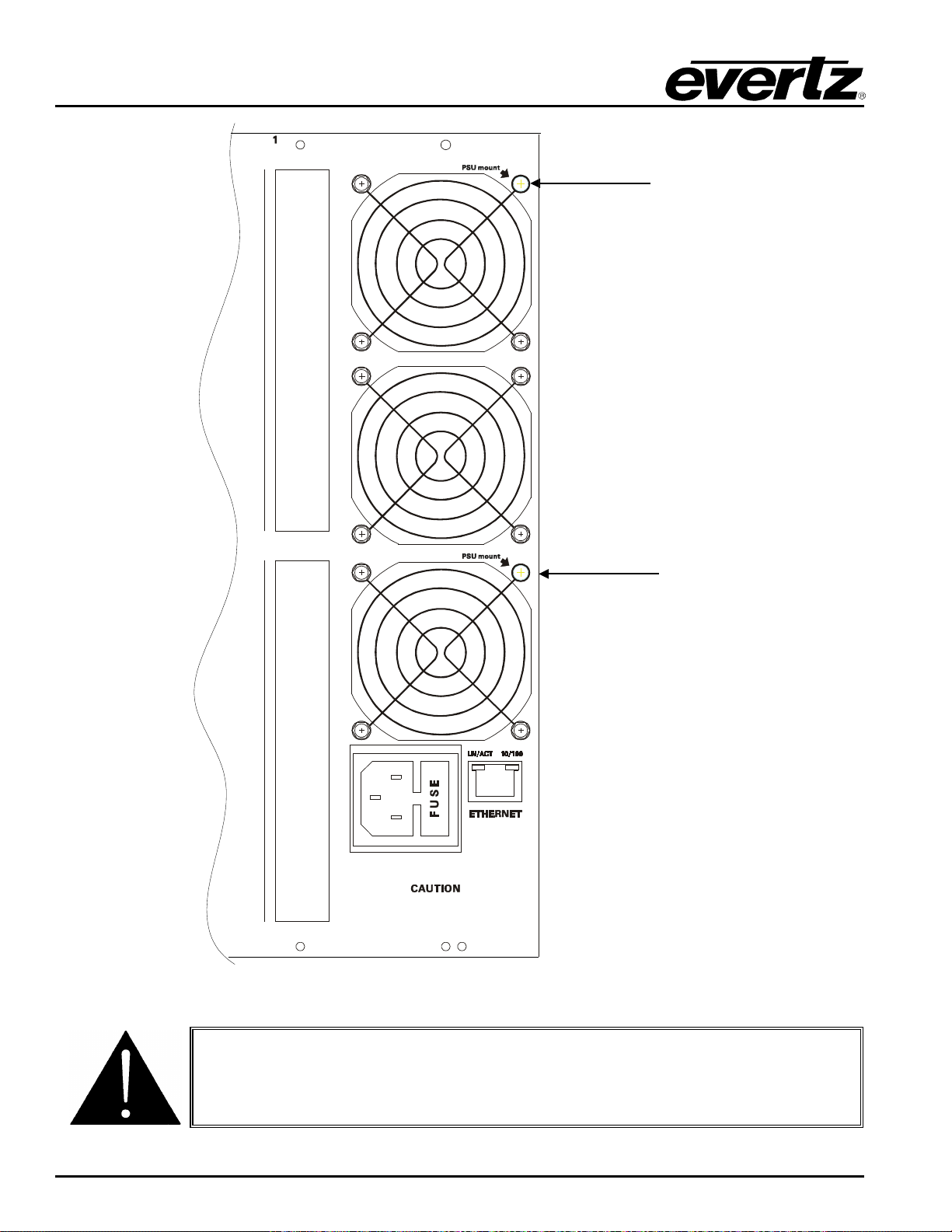
EMR User's Guide
Install
screw
here
Install
screw
here
THIS EQUIPMENT HAS MORE THAN ONE POWER
SUPPLY CORD. TO REDUCE RISK OF ELEC TRIC SHOCK
GROUNDING OF THE CENTER PIN OF POWER SUPPLY
CORD PLUGS MUST BE MAINTAINED. DISCONNECT
BOTH POWER SUPP LY CORDS BEF ORE SERVICING
FUSE: 100-120V: T10AH250V
220-240V: T6.3AH250V
CAUTION: To reduce the risk of electric shock, you must replace the mounting
High Density Modular Audio Router (AES, Analog, MADI, TimeCode, Data)
Figure
screw after replacing the power supply.
Page 86 Revision 1.8 COMPONENT OVERVIEW
2-43: Locating the Power Supply Mounting Screw
 Loading...