

Page 1
Administrator’s Guide
and
Operating Instructions
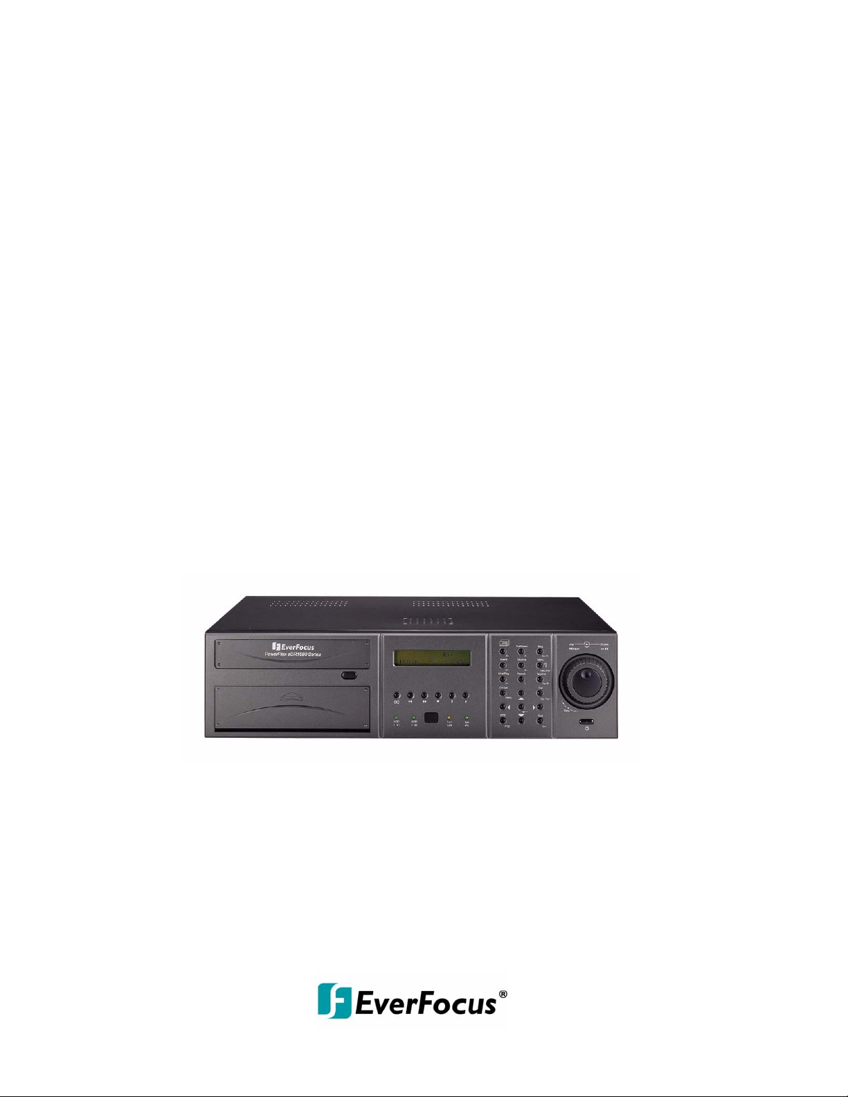
Real Time Digital Video Recorder
eDR1680 Series
V 1.0
1
Page 2
CAUTION
DO NOT REMOVE COVER. NO USER SERVICEABLE PARTS INSIDE.
REFER SERVICING TO QUALIFIED SERVICE PERSONNE L.
WARNING
TO REDUCE RISK OF FIRE OR EL EC TRIC SH OCK,
DO NOT EXPOSE THIS APPLIANCE TO RAIN OR MOISTURE
Safety Precautions
Refer all work related to the installation of this product to qualified service
personnel or system installers.
Do not block the ventilation opening or slots on the cover.
Do not drop metallic parts through slots.This could permanently damage
the appliance. Turn the power off immediately and contact qualified service
personnel for service.
.
Do not attempt to disassemble the appliance.To prevent electric shock,
do not remove screws or covers. There are no user-serviceable parts
inside. Contact qualified service personnel for maintenance. Handle the
appliance with care. Do not strike or shake, as this may damage the
appliance.
Do not expose the appliance to water or moisture, nor try to operate it in
wet areas. Do take immediate action if the appliance becomes wet.
Turn the power off and refer servicing to qualified service personnel.
Moisture may damage the appliance and also cause electric shock.
Do not use strong or abrasive detergents when cleaning the appliance
body. Use a dry cloth to clean the appliance when it is dirty. When the
dirt is hard to remove,use a mild detergent and wipe gently.
Do not overload outlets and extension cords as this may result in a risk of
fire or electric shock.
Do not operate the appliance beyond its specified temperature, humidity
or power source ratings. Do not use the appliance in an extreme
environment where high temperature or high humidity exists. Use the
appliance at temperatur e wit hin 0
The input power source for this appliance is AC100~240V
o
C ~ +40oC and a humidity below 90%.
2
Page 3
Safety Precautions
The lightning flash with an arrowhead symbol, within an
equilateral triangle, is intended to alert the user to the
presence of uninsulated ” dangerous voltage” within the
product’s enclosure that may be of sufficient magnitude to
constitute a risk of electric shock to persons
The exclamation point within an equilateral triangle is
intended to alert the user to presence of important
operating and maintenance(servicing)instructions in the
literature accompanying the appliance.
Warning :
To prevent fire or shock hazard, do not expose units not
specifically designed for outdoor use to rain or moisture.
Attention:
Installation should be performed by qualified service personnel
only in accordance with the National Electrical Code or
applicable local codes.
Warning:
Electrostatic-sensitive device. Use proper
CMOS/MOSFET handing precautions to avoid
electrostatic discharge.
UNPACKING
Unpack carefully.
This is electronic equipment and should be
handled carefully.
Check to ensure that the following items are included;
•1. Digital Video Recorder unit
•2. User’s manual
•3. Power Cord
•4. HDD tray key and screws
•5 Built-in 160 GB HDD
•6. RS232-RS485 converter
If an item appears to have been damaged in shipment,
replace it properly in its carton and notify the shipper.
Do not place on uneven or unstable work surfaces.
Seek servicing if the casing.
Power Disconnect:
Units with or without ON-OFF switches have power
supplied to the unit whenever the power code is inserted
into the power source; however, the unit is operational
only when the ON-OFF switch is in the ON position.
The power cord is the main power disconnect for all units.
AC100~240V Power Cords
Note:
This is a class A product. In a domestic environment this product may cause radio interference
In which case the user may be required to take adequate measures.
Note:
Before installing and using this unit, please read this manual carefully. Be sure to keep it handy for later
reference.
The information in this manual was current when published. The manufacturer reserves the right to revise
and improve its products. All specifications are therefore subject to change without notice.
3
Page 4
Important Safeguards
Read Instruction---All the safety and operating instructions should be read before the init is operated
Retain Instructions---The safety and operating instructions should be retained for future reference.
Heed Warnings—All warnings on the unit and in the operating instructions should be adhered to.
Follow Instructions—All operating and use instructions should be followed
Cleaning—Unplug the unit from the outlet before cleaning. Do not use liquid cleaners or aerosol
cleaners. Use a damp cloth for cleaning
Attachments—Do not use attachment not recommended by the product manufacturer as they may
cause hazards.
Water and Moisture—Do not use this unit near water-for example, near a bath tub, wash bowl,
kitchen sink, or laundry tub, in a wet basement, near a swimming pool, in an
unprotected outdoor installation, or any area which is classified as a wet location.
Servicing—Do not attempt to service this unit yourself as opening or removing covers may expose
you to dangerous voltage or other hazards. Refer all servicing to qualified service personnel.
Power Cord Protection—Power supply cords should be routed so that they are not likely to be walked
on or pinched by items placed upon or against them, playing particular
attention to cords and plugs, convenience receptacles, and the point where
they exit from the appliance.
Object and Liquid Entry—Never push objects of any kind into this unit through openings as they may
touch dangerous voltage points or short-out parts that could result in a fire or
electric shock, Never spill liquid of any kind on the unit.
4
Page 5

Table of Contents
1. Product Features………………………………………………………..………….1
2. Part Names………………………………………………………..…………………2
2.1 Front panel……………………………………………………..………………...2
2.2 Back panel…………………………………………..……………………………3
2.3 Remote Controller…………………………………..…… ………………………4
3. Installation..........……………………………..…………………………….....…….5
4. Function keys illustration………………………..………………………………..7
5. Live Display………………………………………….………………….…………..10
5.1. System Login……………………………………….…………………………..10
5.2. Live Display and Basic Operation…………………….………………………10
6. Setup Menu………………………………………………………… ……………. ..12
6.1. Setup Menu Flowchart…………………………………………………………13
6.2. Camera Setup……………………………… ……………… …… ……………. 1 4
6.2.1. Global Configuration ……… ………… …………….… … ……………… .14
6.2.2. Camera-Advanced S et u p ………… …… ……………… …………. …... 15
6.2.3. Camera-Global Setup ……………… …… ……………. ………… …… .. 19
6.3. Calendar Setup ……………………………………………………….……20
6.4. System Setup…………………………………………………………………...21
6.4.1. System-General Setup ..…………………………….……………….….21
6.4.2. System-HDD Setup ..……………… …… ………… …. ……………… ... 2 2
6.4.3. System-Alarm Input Setup ..………………………….…………………23
6.4.4. System-Network Setup ….…………………………….…………….…. 25
6.4.5. System-Dial-up Setup .. …………… …… ………… ….. ……….…. …… 2 7
6.4.6. System-E-Mail Setup……………… …… …………….. ……….… …. ….. 2 7
6.5. Display Setup
6.5.1. Display-Main Monitor Sequ e nc e S et u p .. ……………… …..…… …….. 28
6.5.2. Display-Call Monitor Seque nce Se t up ..………… …… …………….. … 2 9
6.6. Password Setup… ………………………………………………….…….……..30
6.7. Logout .........................................................................................................31
7. Playback and Search recorded Images ……………………………………...…32
7.1. Video Playback………………………………………………………...………..32
7.2. Search Recorded Images……………………………………………………....33
7.2.1. Search by Time………….….………………………… ……….. …..……. 3 3
7.2.2. Search by Location………. ….……… …………… ………..…… …….. .. 3 3
7.2.3. Search by Event…………………… ……………… …… ………... ……. .34
7.2.4. Smart Search………………………………………...…… ………… …... 34
8. Video Archive and Preview………………………………………………………..35
8.1. Video Archive…………………………………………………………………....35
8.2.Preview Archived Video…………………………………………………..……..36
9. Event Log……………………………………………………………… ……..…….. 3 7
10. PTZ Control………………………………………………………………………...38
11. View from Internet / Intranet ……………………………………………..……39
Appendix A – Specifications ………………………………………………..........… 45
Appendix B – Time Lapse Mode Recording Time .............................................. 46
Appendix C – Simulated Keyboard ...................................................................... 48
Appendix D – Q & A .............................................................................................. 49
…………………………………………………………………….…... …28
5
Page 6

1. Product Features
16/8 CH Real-Time Digital Video Recorder
Quadruple operation: Recording, Live view, Playback & Remote viewing
16/8 Color and/or B/W camera inputs (NTSC/PAL)
MPEG-4 compression with resolution up to 720*480 (NTSC) / 720*576 (PAL)
Real time recording (up to 25/30 FPS) per channel
Real time live display (up to 25/30 FPS) per channel
Real time playback (up to 25/30 FPS) per channel
16/13/10/9/7/4 windows or full-screen display
4 audio inputs, 1 audio output.
Synchronized video & audio
Video/audio storage in 1 built-in IDE HDD, 1 hot swappable IDE HDD
Programmable storage for highest surveillance availability.
1 IDE CD-RW for video/audio backup.
Non-editable video/audio data.
Motion detection with programmable area and sensitivity for each camera.
Alarm processor with configurable triggering conditions and reactions
Alarm history log for Video Loss, Motion, Alarm input, etc.
Pre-record time: up to 10 seconds.
Sophisticated PTZ control functions, including Pan, Auto pan, Tilt, Zoom, Focus,
Speed, Preset locations, Sequence, etc.
RS232 ports for modem ( Modem function reserved ) connection and PTZ control.
Optional SCSI connector for additional backup devices.
Ethernet connector for internet/intranet access.
Remote alarm notification via e-mail, dial-out, etc.
ActiveX support for third-party software integration & networking CCTV applications.
Multi-level password to ensure high degree of security.
Multi-lingual support.
TV monitor out and VGA monitor out
Call (spot) monitor out
Front panel LCD & LEDs
Input devices: Keypad & Jog-shuttle, and I/R remote controller (1 I/R remote controller
can control up to 4 eDRs)
Built-in Compact Flash, power off data protection, power on and run
Built-in RTC
Hardware WDT
6
Page 7
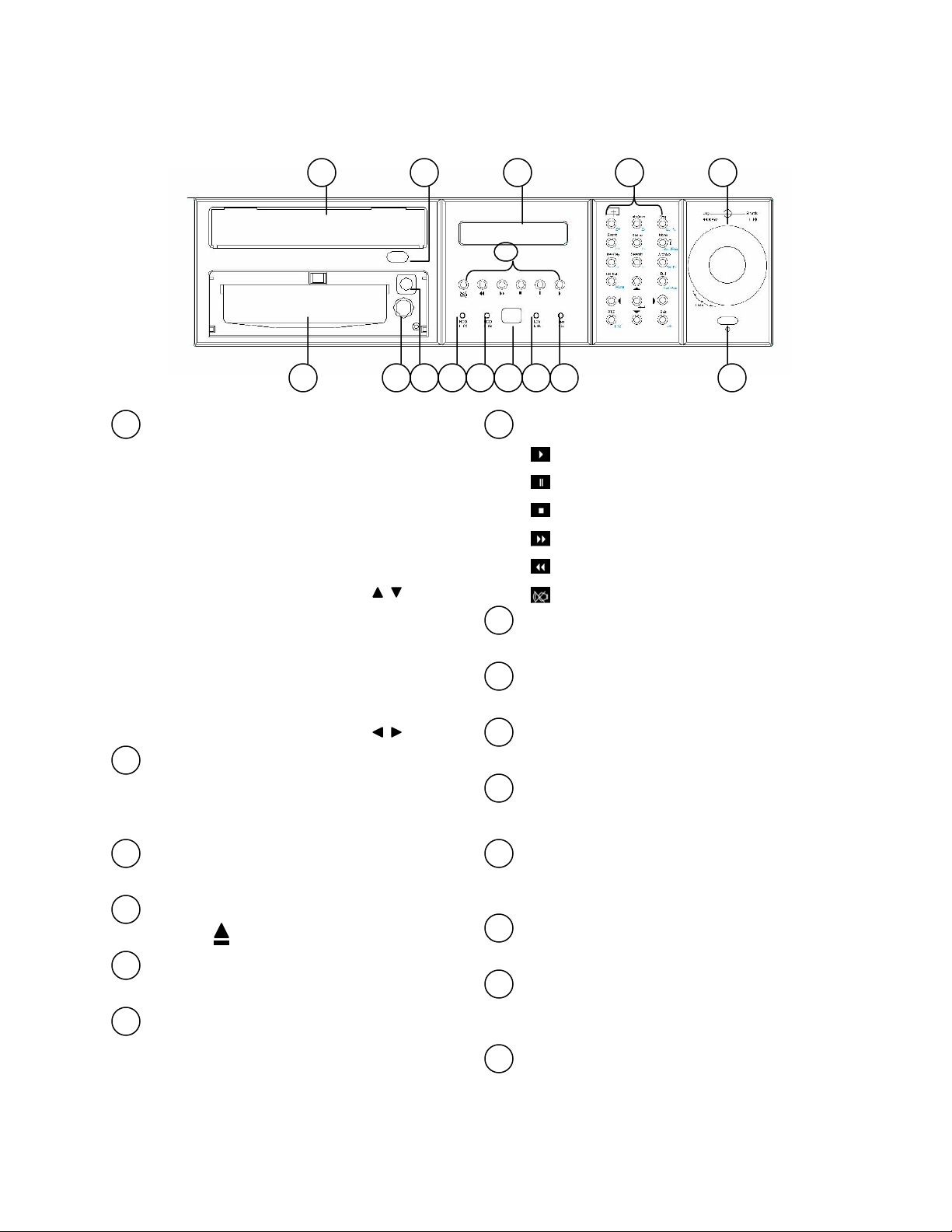
2. Part Names
2.1 Front Panel
124 35
7
1
Jog Dial (inner) and Shuttle Ring (outer)
Jog Dial:
A. Rotate in paused playback to move
forward or backward to the next recorded
image
B. In Setup Menu, rotate to select the
options in the column (Same as keys)
Shuttle Ring:
A. Rotate in playback to search the
recorded images in variable speed.
B. In Setup Menu, rotate to select the
options in the column (Same as keys)
2
Function Keys Panel
General Mode Panel(white) and PTZ Control
Panel (Cyan). Please refer to Chapter 5 for
detail function.
3
LCD Panel
8
1112131415
910
7
Playback Buttons
6
Press to start playback
Press to pause playback
Press to stop playback
Press to fast forward playback
Press to fast rewind playback
Press to mute status On/Off
8
LAN Active Indicator
Flashed when LAN is accessed.
9
LAN Link Indicator
Illuminates when LAN is connected.
10
IR Receiver
For IR Remote Controller (ERC100)
11
HDD I02 Indicator (Internal HDD)
Illuminates when HDD I02 (hot-swappable)
is accessed.
12
HDD I01 Indicator (Internal HDD)
To display the Date/Time, Recording status, etc.
4
Eject Button
Press to eject CD-RW disc tray.
5
CD-RW
Built-in CD-RW.
6
Power Switch and Indicator
Press to turn On/Off the power.
Illuminates when HDD I01 (built-in) is
accessed.
13
HDD Tray Lock
Lock the tray to e nable the HDD I02 application.
14
DVR ID Switch
Switch the controlled ID (DVR1~DVR4) for
ERC100 controller. The default setting is DVR 1.
15
HDD Tray
HDD I02 (hot-swappable)
7
Page 8
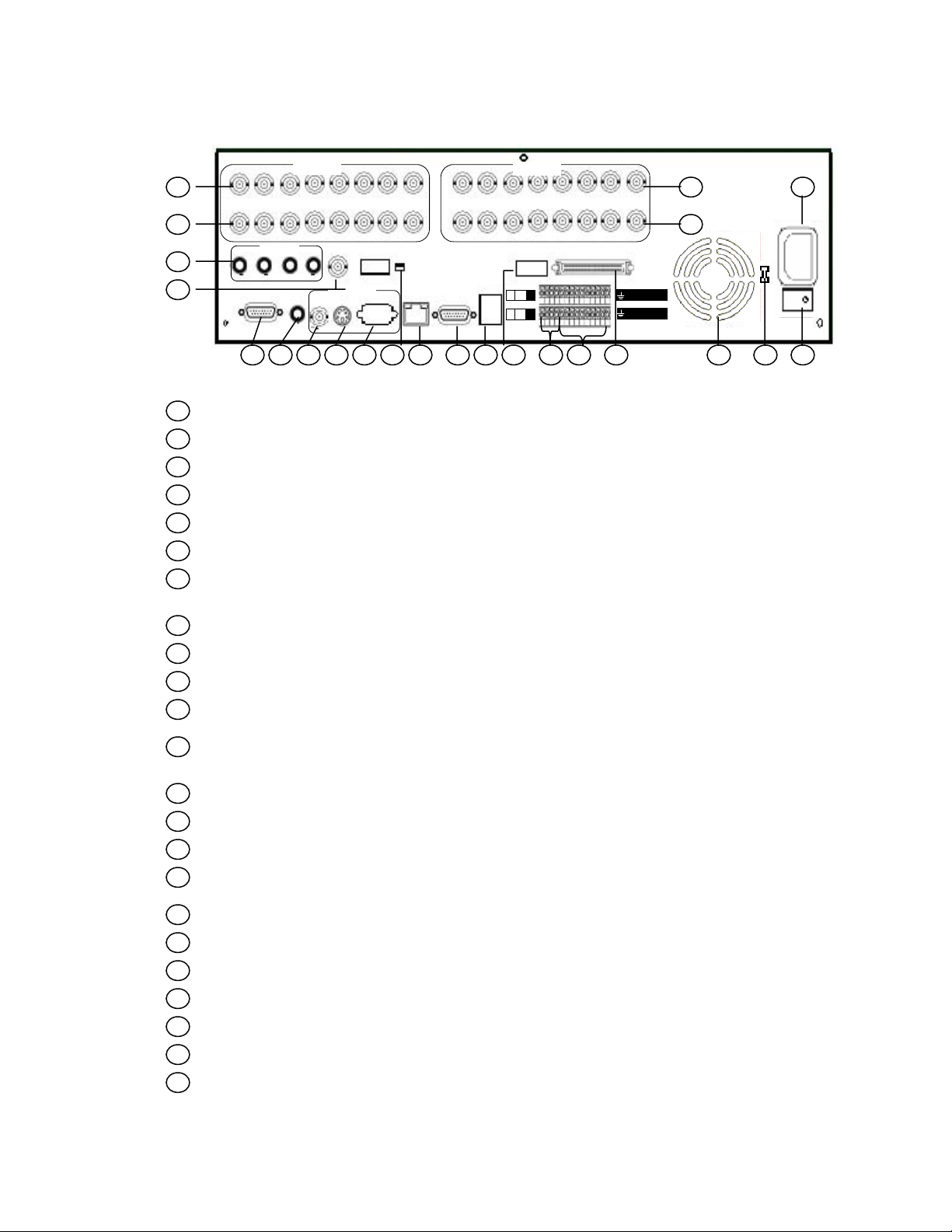
2.2 Back Panel
A
9
In
1
2
23
22
V1 V2 V3 V4 V5 V6
Out
udio In
1 2 3 4
Audio
RS232#1
Out
Video 1-8
Call Monitor
CVBS
1-8
Main Monitor
Y/C
75
VGA
Ω
V7 V8
NTSC/PAL
LAN
In
Out
RS232#2
Video 9-16
V9 V10 V11 V12
75
9-16
Alarm Out
USB
2 1 C
4 3
NC
NO
6 5 C
8 7
V13 V14
Ω
SCSI
V15 V16
16 15 14 13 12 11 10
Alarm In
8 7 6 5 4 3 2 1
53
4
Power
21
1
Video Input Connectors (Video In 1-8): BNC connectors for video input 1-8
2
Video Output Connectors (Video Out 1-8): BNC connectors for video looping out 1-8
3
Video Input Connectors (Video In 9~16): BNC connectors for video input 9~16 (eDR1680)
4
Video Output Connectors (Video Out 9~16): BNC connectors for video looping out 9~16
5
Main Power Socket: The main power input.
6
Power Switch: Power On/Off.
Power Selector Switch: 115V AC or 230V AC selector switch. Warning: To avoid damaging
7
the system, set this switch before plugging in the power plug. Use a screwdriver to set th e
15
12 11
10 9 8 7 614 131619 18 1720
switch to the correct position so that the number shown is the same as the local AC voltage.
8
Cooling Fan
9
SCSI Connector: For connecting the optional extension unit. (Reserved)
10
Alarm Inputs: Connect to alarm inputs 1-16 and 2 common grounds
11
Alarm Outputs: Connect to 4 Normally Closed alarm outputs (1,2,5,6), Normally Open alarm
outputs (3,4,7,8) and 2 common grounds.
12
75ohm Termination 9-16: The termination should be set as On normally. However, if the
corresponding camera is connected to other devices, please set it as off
13
USB Connector: Reserved.
14
RS232 connector #2: Connects to PTZ camera.
15
LAN connector: Connects to RJ45 LAN connector.
16
Video System Switch
before system starts up
17
Main Monitor VGA Output: VGA connector
18
Main Monitor Y/C Output: Mini-Din S-Video connector
19
Main Monitor CVBS Output: BNC connector, connects to TV monitor input
20
Audio Output Connector (Audio Out): Audio output to an external device (Speakers)
21
RS232 connector #1: Connects to Modem (Modem Function Reserved)
22
Call Monitor Output: BNC connector for Call (spot) monitor
23
Audio Input Connectors (Audio In 1-4): Audio input from an external device Mick)
: NTSC / PAL manual switch. Please make sure to select the proper video system
8
Page 9
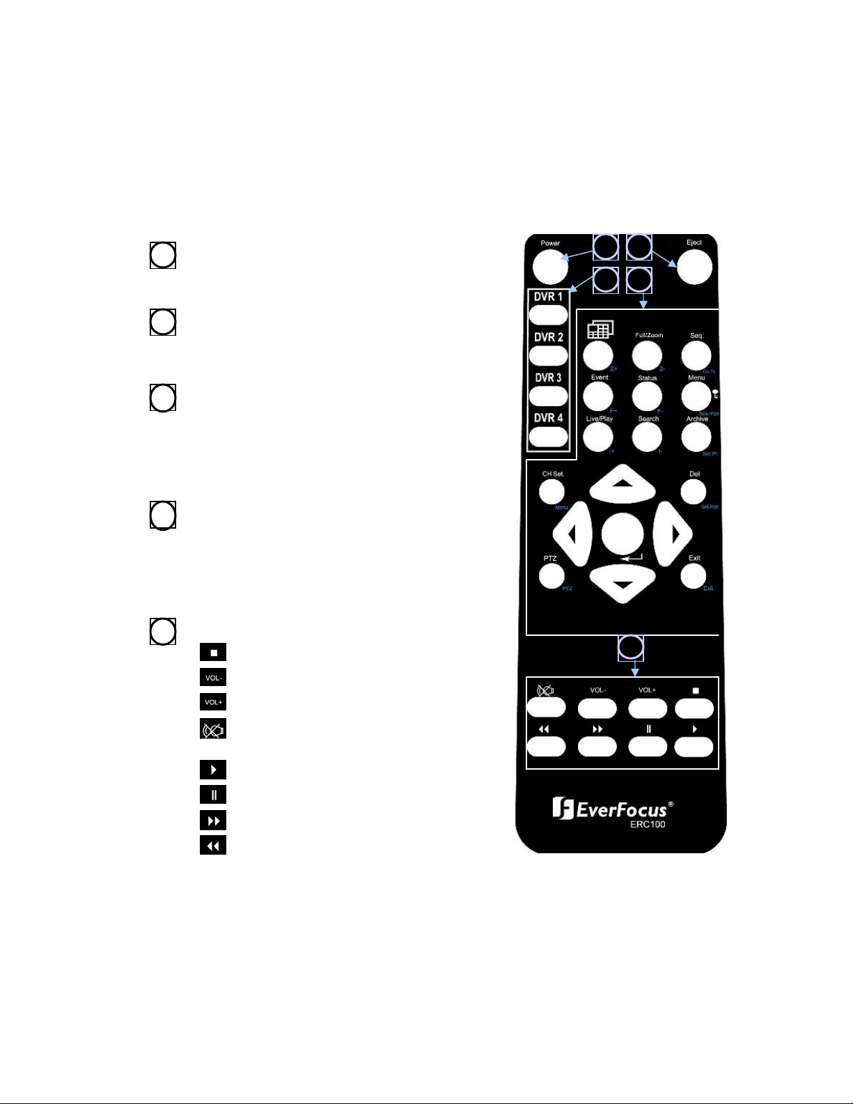
2.3 Remote Controller
The ERC100 remote controller is an accessory to enhance the handy operations. You can
do all the settings and operations by the remote controller. The effective distance is up to
10 meters without any obstacle.
Power Button
1
Main Power ON/OFF
Eject Button
2
Press to control the ejection insertion
of the CD-RW disc tray.
ID Buttons
3
One Remote Controller can control up
to 4 DVRs. Press the buttons to switch
the controlled ID (DVR1~DVR4). The
default setting is DVR 1.
Function Buttons
4
General Mode Panel (white), PTZ
Mode Panel (Cyan)
Please refer to Chapter 4 for detail
functions operation.
Playback Buttons
5
Press to stop playback
1 2
3 4
5
Press to adjust the audio volume low
Press to adjust the audio volume high
Press to mute status On/Off
Press to start playback
Press to pause playback
Press to fast forward playback
Press to fast rewind playback
9
Page 10
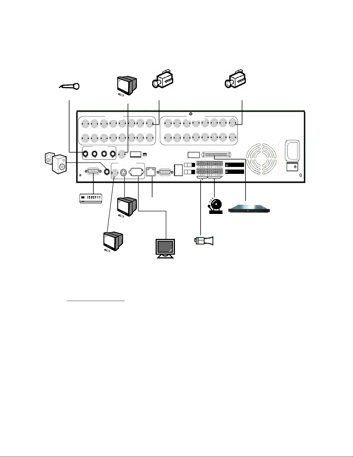
3. Installation
A
9
Audio In 1~4
Audio Out
Call Monitor
udio In
Video 1-8
Audio
Out
Call Monitor
CVBS
In
V1 V2 V3 V4 V5 V6
Out
1 2 3 4
RS232#1
Modem
Main Monitor (Y/C)
Main Monitor (CVBS)
1-8
Main Monitor
Y/C
Camera In 1~8 Camera In 9~16
USB
Video 9-16
75
9-16
Alarm Out
2 1 C
4 3
NC
NO
6 5 C
8 7
V13 V14
Ω
SCSI
75
VGA
V7 V8
Ω
NTSC/PA L
LAN
In
Out
RS232#2
V9 V10 V11 V12
Ethernet
Alarm In
Alarm Out
V15 V16
16 15 14 13 12 11 10
Alarm In
8 7 6 5 4 3 2 1
Disk Array
Power
Main Monitor (VGA)
Basic Connection
Cameras
Connect each camera video input connector to the video output from a camera or other
composite video source.
Main TV Monitor
Connect the Main monitor output connector to a TV monitor. The TV monitor displays selected
live or recorded cameras in any available format.
Power
Plug the 110V AC or 220V power source into the power socket.
10
Page 11
Optional Connection
VGA Monitor
Connect the VGA monitor output connector to a VGA monitor. The VGA monitor displays
selected live or recorded cameras in any available format.
Call Monitor
Connect the Call monitor output connector to a TV monitor. This monitor displays the full screen
images of cameras associated with alarms or images from the installed cameras sequentially.
Alarm In
Connect Alarm In 1-16 to NC or NO type of alarm signals. Please make sure to setup the
software configurations of Alarm In accordingly.
Alarm Out
Connect Alarm Out 1,2,5,6 to NC type of alarm signals, Alarm Out 3,4,7,8 to NO type.
Microphone/Speaker
Connect the microphone/speaker or other audio devices to the Audio In/Audio out connector.
PTZ Camera
Connect a PTZ camera to the RS-232 (Com#2) connector at system start up.
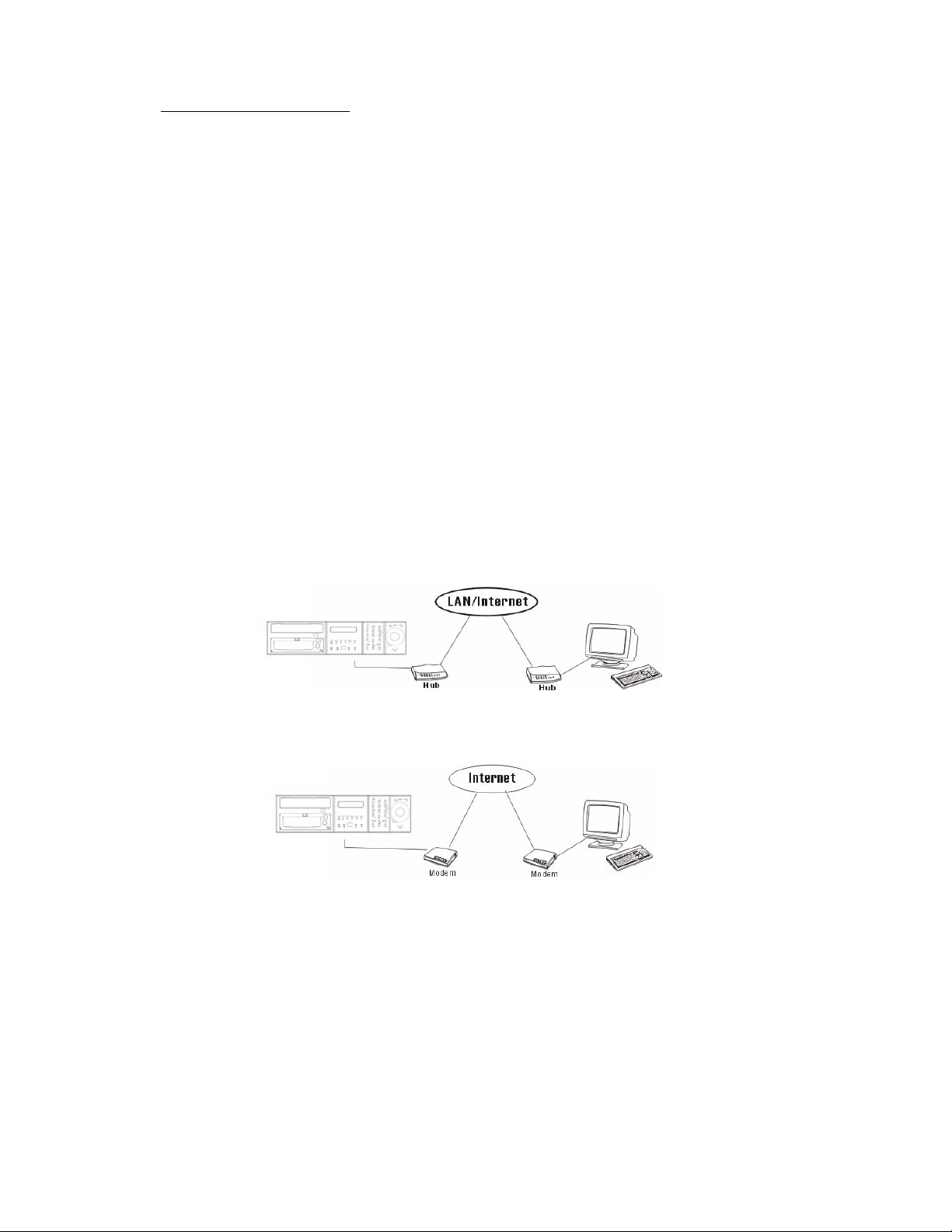
Ethernet
The system is enabled control from the PC via Ethernet. Connect the LAN connector to a
standard RJ45 connector Ethernet cable. Shown in below is an example of the connection. .
Modem ( Modem Function Reserved)
The system is enabled control from the PC via modem. Connect the RS 232 Connector (Com#1)
to a modem. Shown in below is an example of th e con n ecti on.
ISDN
The system is enabled control from the PC via ISDN. Connect the ISDN TA device to the RS
232 connector (Com#1).
Disk Array
It is allowed to connect additional hard disk array (EDA400) for extensional storage.
11
Page 12
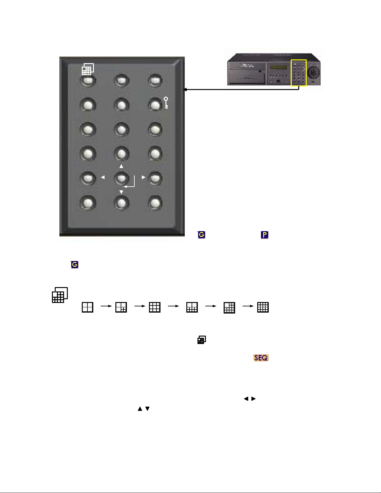
4. Function Keys Illustration
Full/Zoom Seq.
Go Pr.Z+ Z-
Event
Live/Play
CH Set Del
Auto Pan Set Pan
PTZ
Status Menu
F+ F-
Search Archive
I+
Seq. Pr.
I-
Set Pr.
Exit
The Function Key Panel can operate 2 levels
function-General Mode and PTZ Control Mode.
The levels are distinguished by icon colors:
General Mode – White ( For EDR1680 operation)
PTZ Control Mode– Cyan (For extensional PTZ
camera if connected)
The default panel function is under General Mode.
Press “PTZ” button to switch to PTZ control function.
Press the buttons again to switch back to General
Mode.
PTZ
Exit.
On main monitor display, there is a icon shown on the
right lower corner. It shows the operation mode.
General mode PTZ control mode
4.1 General mode operation.
Press to change display split mode according to following cycle.
Full/Zoom Switch the focus window to full screen mode. Press again to Digital Zoom-in (X2) the
selected area (Show X2 at the right lower corner on the display). Press again to return to previous static
display. On Full screen display, you may also press to return to previous static display.
Seq. Press to toggle between Sequence Mode and Static Mode (Show at the right lower corner
of screen). Press again to return to static mode.
Note: In Seq mode, press Status to display Date/Time, HDD storage status. Press Menu, Event,
Archive & CH Set, return to Static Display.
Event Press to appear Event Log Dialog. Press Exit to return. Use buttons or Shuttle to
move the focus among items, or Jog to select option from the list.
Note: Press Del button can delete selected event list.
12
Page 13
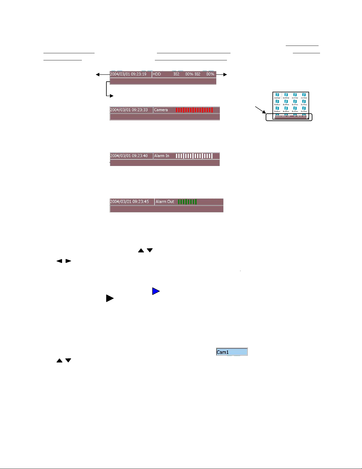
Status There are four types of status display on the bottom of the screen. Press to display Date/Time &
HDD storage status. Press again to display Date/Time & Camera Status. Press again to display Date/Time
& Alarm Inputs. .Press again to control the Date/Time & Alarm Outputs Press again to close the display.
Date/Time
Show the details if motion or alarm triggered.
From left to right, each light stand for camera 1~16 (eDR880=1~8)
Green=Recording, Grey=Not Recording, White=Uninstall, Yellow=Motion, Red=Video Loss
From left to right, each light stand for Alarm Input 1~16 (eDR880=1~8)
Green=Normal, Red=Alarm triggered, White=Alarm In setting off
Green= Alarm out setting ON. White= Alarm out setting OFF
HDD recorded percentage
Menu Press to appear Setup Menu Dialog. Press Exit to return. In Setup Menu, press Enter button to
enter the selected setup menu. Press or turn the Jog to move between the rows (For Up and Down).
Press or turn the Shuttle to move between main menu and submenu (For Left and Right). Please
refer details for menu setting in chapter 6.
Live/Play Press to select between Live Mode or Playback Mode for focus channel.
Once select the Playback Mode, there is a show on the right upper corner of the
selected channel. Press on the payback buttons to start playing back. Please refer to
Chapter 7.1 for details.
Search Press to show Search Dialog for playback. Press Exit to return. Please refer to Chapter 7.2 for details.
Archive Press to show Archive Dialog for archiving to CD-RW. Press Exit to return. Please refer to
Chapter 7.2 for details.
CH Set Press to set display camera on focus window. The dialog will show on focus channel.
Press or turn the Jog to select desired camera then press Enter to confirm setting. Press Exit to leave
the dialog.
Note: Each channel is allowed only to show at once. It is not able to appear same camera in different
windows in the same split display.
Del In Event Log Dialog, press to delete event list. In the column where need to edit character, press to
delete one character each time (Same as Back Space).
13
Page 14

A. Press to move focus window Up, Down, Left & Right in live display mode.
B. In setup Menu Dialog, press to move between columns (Same as Shuttle), press to
select options (Same as Jog).
C. Once the Simulated keyboard pop up, use to move among the alphanumeric keys. (Same as
JOG)
(Enter)
A. In Main Menu Setup, press to enter the Menu Dialog.
B. Press to save the configuration.
C. In Motion Detection Setup, press to toggle the Detect Area.
D. Press to confirm the select channel in CH set operation.
Exit Press to return to upper level or leave current dialog without saving.
4.2 PTZ mode operation.
If there is a compatible PTZ camera connected to the DVR, you may switch between PTZ mode or
General mode to operate the PTZ camera or DVR by pressing the PTZ button on the front panel.
(Current available models: EverFocus EPTZ series, ED2200. Pelco D protocol dome, C1487M.
Kalatel Cyber Dome. Phili ps Auto Dome. Samsung SCC-641P, SPD-2500. Subject to further notice if
there is update support protocol)
Z+ : Zoom In Z- : Zoom Out
F+ : Focus Far F- : Focus Near
I+ : Open IRIS I- : Close IRIS
GO Pr : Goto Preset position. The dialog will show on the f ocus camera. Use to
select the preset position 1~10.
Seq Pr : Sequence tour on preset position 1~10. The dialog will show on the focus camera.
Use to select the dwelling time. Use to move to “OK” icon and press (Enter) to start.
Set Pr : Set Preset position. Pan/tilt/zoom the camera to desire position and then press this button, the
dialog will show on the focus camera. Use to select desired position and press
(Enter) to confirm the setting position. Press “Exit” to leave the dialog .
Auto Pan : Press to start Auto Pan (left to right). T he dialog will show for further sett ing of
the pan speed as you need. Move ( ) to “OK” icon to start auto pan.
Set Pan : Set Auto Pan Scope
: Press to Pan/Tilt the camera (Pan=left/right, Tilt=up/down)
Exit : Press to leave setting dialog without saving.
14
Page 15

5. Live Display
5.1 System Login
If the user does not login the system, he will be treated as a guest and can only view the live video
and system status. To login the system, press (Menu) button, the system login dialog and
simulated keyboard will appear on screen as below allowing user to enter appropriate Login name
and password. (For Operator, the factory default value for both is operator
factory default value for both is supervisor
admin
)
Use or JOG to move among the alphanumeric keys.
Press “Enter” button to confirm the selected character. Move to <- key and press “Del” button can
delete the wrong character inputted if necessary.
, for Administrator, the factory default value for both is
, for Supervisor, the
Use or Shuttle to move to next row (Tab).
After finished all necessary inputs of username and password, use or Shuttle to move to “Login”
icon and then press “Enter” button to login the system.
5.2. Live Display and Basic Operation
SEQ G
The screen above is the main display (monitor) after the system starts up and user login.
The display resolution is 640x480(NTSC), 800x600(PAL). The display mode and function key panel
status will be shown on the screen as following:
G
General mode for DVR operation PTZ control mode Sequential mode display
SEQP
15
Page 16
There is always a focus window surrounded by a white frame and it can be moved among split
windows by using buttons.
Full/Zoom Switch the focus window to full screen mode. Press again to Digital Zoom-in (X2) the
selected area (Show X2 at the right lower corner on the display). Press again to return to previous
static display. On Full screen display, you may also press to return to previous static display.
Multi-window display
Press to change display different split windows according to following cycle.
Display Camera Setup
Move the focus to the desired view window, press “CH Set” button and the camera selection Dialog
will appear on the screen. Press or turn the Jog to select desired camera then
press “Enter” button to confirm setting. Press “Exit” button to leave the dialog.
Note: Each channel is allowed only to show at once. It is not able to appear same camera in
different windows in the same split display.
Sequence Display Mode
Press “SEQ” button to toggle between Sequence and Static Display Mode.Sequence can be
displayed in various split windows. Press the Sequence Display Mode, user may view the Status
and control the Alarm Outputs. The other function keys will be disabled until it’s switched back to
Static Display Mode.
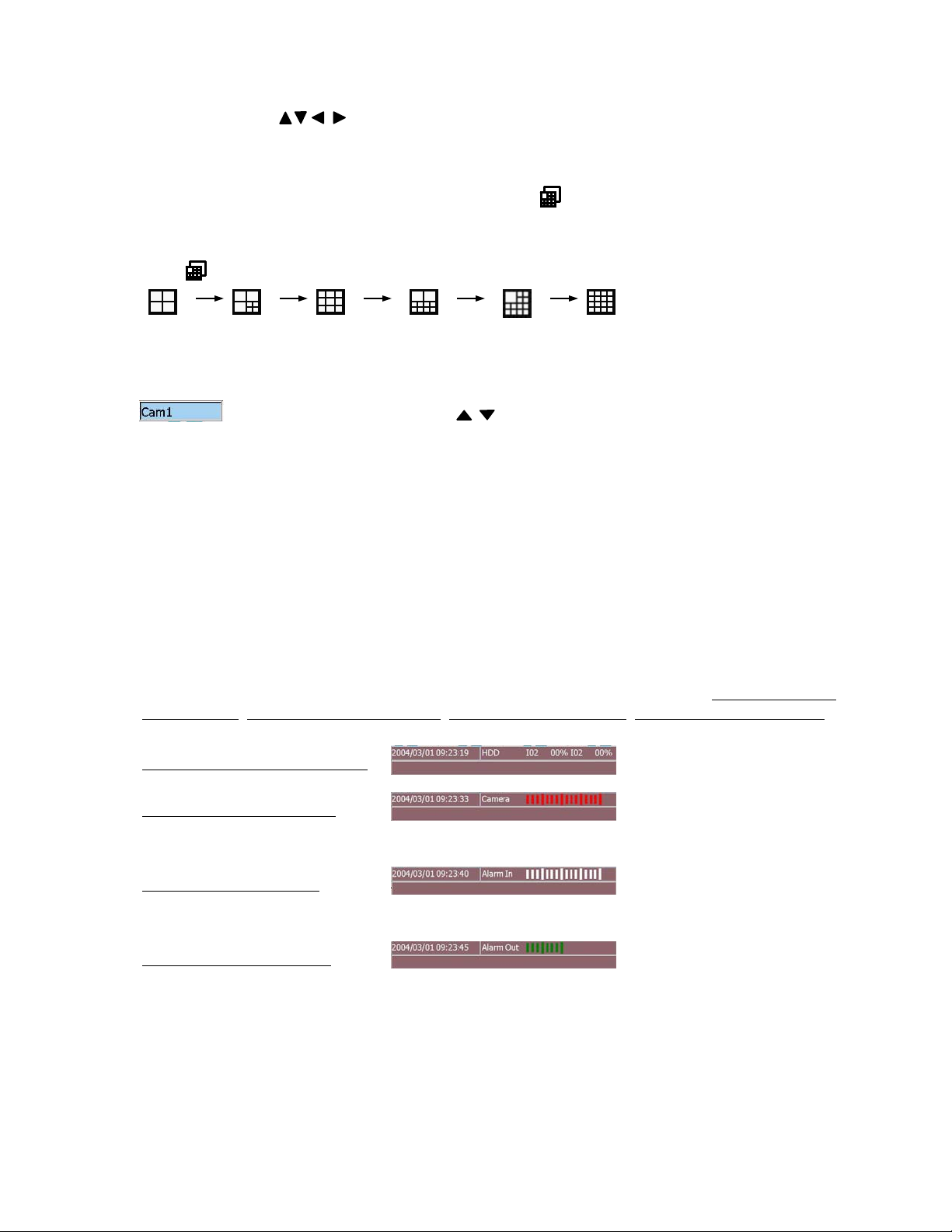
Status Display
There are four types of status display on the bottom of the screen
storage status, Date/Time & Camera Status, Date/Time & Alarm Inputs, Date/Time & Alarm Outputs
accordingly.
Date/Time & HDD storage status
Date/Time & Camera Status
(Green=Recording, Grey=Not Recording, White=Uninstall, Yellow=Motion, Red=Video Loss)
Date/Time & Alarm Inputs
(Green=Normal, Red=Alarm triggered, White=Alarm In setting off)
Date/Time & Alarm Outputs
(Green= Alarm out setting ON. White= Alarm out setting OFF)
. Press to display Date /Time & HDD
Clean Message / Alarm Reset
When the alarm is activated, press any button first time to clean the alarm message.
16
Page 17
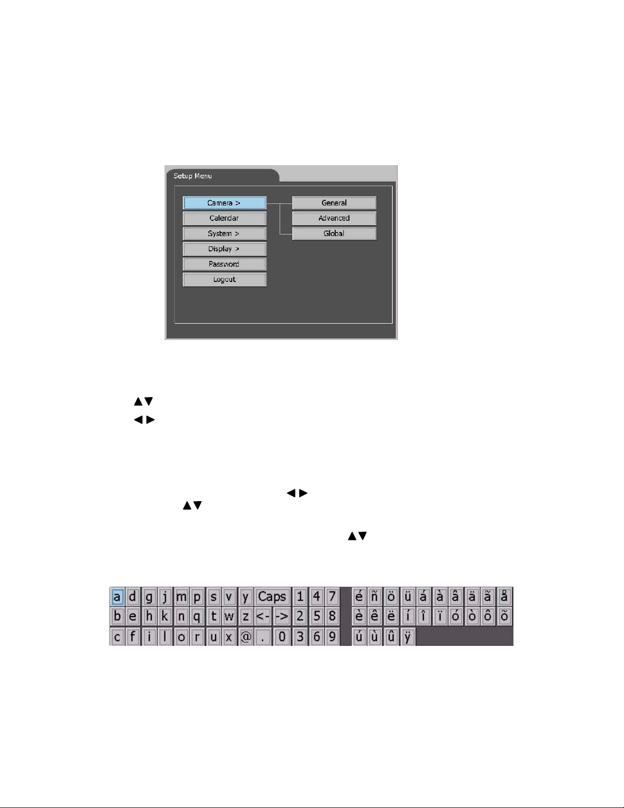
6. Setup Menu
For entering the system setup menu, the user has to login as an Administrator level.
To setup the behaviors of the system, please press “Menu” button on the front panel. The Setup
Menu shown as below will appear on screen.
Use buttons or “Jog” to switch items in the row.
Use buttons or “Shuttle” to enter the submenu or return to upper level.
Press “Enter” button to close Setup Menu and enter the selected Configuration Dialog.
The “>” shows on the item means a submenu is available for further configuration.
Generally, in Configuration Dialog, buttons or “Shuttle” are used to move the focus
among items, or “Jog” to select parameter from the list in the item and Exit to r eturn
to upper level.
If the simulated keyboard pop up for editing, u se or “Jog” to move between the
alphanumeric key. Press “Enter” to confirm the character.
17
Page 18

6. 1 Menu flowchart
Camera >
Calendar
System >
General
Advanced
Global
General
Hard Disk
Alarm Input >
Motion Detection
Motion Action
VLoss Action
Alarm Action
Display >
Password
Logout
Network
Dial-up
E-mail
Main Monitor Seq
Call Monitor Seq
18
Page 19

6.2 Camera Setup
6.2.1 Camera-General Setup
Figure 1
Camera Tag
Default settings are Cam1~Cam16 (Cam1~Cam8 for eDR880). User may move to “Edit” icon
and press “Enter” button (Simulated keyboard will pop up once you start the edit functionFigure 1) to edit the camera title (total 10 characters available). Move to “OK”icon after
finished and press “Enter” to confirm editing. Press “Exit” button to return to previous dialog.
Installed
Select “ON” if the corresponding camera is installed. All the other items are settable if the
selected camera is installed. Default value is “ON”.
Tag Color
10 options, select the desired camera tag color.
Blackout
Select “ON” to enable blackout the corresponding camera. The Guest and Operator levels are
not able to view the live/playback image of the corresponding camera while the blackout
function is selected. Default value is “OFF”.
Rec Quality (Recording Quality)
6 options (0~ 5), 5 is the best picture quality. The default value is 3.
PTZ ID
Select ID values while the installed camera is a PTZ device. Select N/A if the corresponding
camera is not a PTZ device. Default value is “N/A”.
Brightness, Contrast, Hue, Saturation
Adjustable for each camera
19
Page 20

6.2.2 Camera-Advanced Setup
Camera Tag
Select the corresponding camera Cam1~Cam16 for further setting.
Time Type
4 options of time type are available. Default value is “On Duty”. The setting of each time type
please refer Chapter 7 Calendar setup menu.
Motion
Select “ON/OFF” to enable/disable the Motion detection for corresponding camera.Default
value is “ON”. While the “ON” option is selected, the Config icon will be enabled for user
to configure the motion detection behavior. Move the focus to the icon and press “Enter”
button to show the Motion Detection Setup Dialog as following:
->
20
Page 21

Motion Detection Setup
Mask Type
3 Options (4x3, 8x6, 16x12). Select the size of the mask that will be used to configure the
motion detection area in the view window. Default value is 16x12.
Mask Select
3 Options (Select All, Clear ALL, User define). Select the initial masked area.
Sensitivity
3 Options (High, Mid, Low). Default value is Middle sensitivity.
Detection Area Setting
Move the focus to the picture area. Use
“Enter” button to toggle on/off the grid.
Press “Exit” button to leave the picture
grids area.
Motion Act (action)
Maximum 4 options. Define the corresponding Motion Action while motion detection is
enabled. .Default value is “MotionA01”. Move the focus to the Config icon will be enabled
for user to configure the motion action behavior. Move the focus to the icon and press “Enter”
button to show the Motion Action Dialog as Figure 1:
->
Figure 1 Figure 2
Action Tag
Move the focus to “Edit” icon and press “Enter” button to edit action tag if necessary. Simulated
keyboard will pop up once user starts the edit function (Figure 2) to edit the Action Tag (total 10
characters available). Move to “OK” icon after finished editing and press “Enter” button to confirm
editing. Press “Exit” button to return to previous dialog
Pre-Recording
Define the pre-recording time (0~10 seconds) for corresponding camera. Default value is 5 Sec.
21
Page 22

Post-Recording
Define the post-recording time (0~99 seconds) for corresponding camera. Default value is 10 Sec.
Alarm Output
To define which Alarm Output will be triggered when the Motion Action is triggered. Alarm Output
1,2,5,6 are NC type of signal, Alarm Outp ut 3,4 , 7, 8 are No type .S e lect N/A to disabl e alarm
output.Default value is 1 (alarm output 1).
Buzzer
To activate (ON) buzzer or not (OFF) while motion is triggered. Default value is “ON”.
Call Display
If Call Display function is enabled (ON), the call monitor will switch to the focus camera when the
Motion Action is triggered. Default value is “ON”.
Log
Log to event log list or not. Please refer to Event Log for the details. Default value is “ON”.
Show Message
To display the alarm message or not when the Motion Action is triggered. Default value is “ON”.
E-mail
To activate the E-mail notification function or not when the Motion Action is triggered. The E-mail
will be send to the defined receivers with an attached file, which contains the video graphic file f the
triggered moment. Please refer to E-Mail Configuration for detail setting. (Note)
Network Alarm
Reserved for the PowerCom (Optional) users. Please refer to the PowerCom user manual for the
detail information.
Note: If a new motion action is happened during the post record time from the previous
triggered motion, there will be no notification sending for the corresponding action.
22
Page 23

VLoss Act (video loss action)
Maximum 4 options. Define the Video Loss Action for corresponding camera.Default value is
“VlossA01”. Move the focus to the Config icon will be enabled for user to configure the
video loss action behavior. Move the focus to the icon and press “Enter” button to show the
Video Loss Action Dialog as Figure 1:
Figure 1 Figure 2
Action Tag
Move the focus to “Edit” icon and press “Enter” button to edit action tag if necessary. Simulated
keyboard will pop up once user starts the edit function (Figure 2) to edit the Action Tag (total 10
characters available). Move to “OK” icon after finished editing and press “Enter” button to confirm
editing. Press “Exit” button to return to previous dialog
->
Pre-Recording
Define the pre-recording time (0~10 seconds) for corresponding camera. Default value is 5 Sec.
Post-Recording
Define the post-recording time (0~99 seconds) for corresponding camera. Default value is 10 Sec.
Alarm Output
To define which Alarm Output will be triggered when there is video loss of corresponding camera.
Alarm Output 1,2,5,6 are NC type of signal, Alarm Output 3,4,7,8 are No type. Select N/A to
disable alarm output.Default value is 1 (alarm output 1).
Buzzer
To activate (ON) buzzer or not (OFF) while motion is triggered. Default value is “ON”.
Duration
To define the duration time of the Alarm Output while there is video loss of corresponding camera.
Log
Log to event log list or not. Please refer to Event Log for the details. Default value is “ON”.
Show Message
To display the alarm message or not when the Motion Action is triggered. Default value is “ON”.
E-mail
To activate the E-mail notification function or not when the Motion Action is triggered. The E-mail
will be send to the defined receivers with an attached file, which contains the video graphic file in
the triggered moment. Please refer to E-Mail Configuration for detail setting.
Network Alarm
Reserved for the PowerCom (Optional) users. Please refer to the PowerCom user manual for the
detail information.
23
Page 24

6.2.3 Camera-Global Setup
The Global Setup allows administrator to define the common behaviors for all the
installed cameras. The settings below will apply to all installed cameras.
Time Stamp
Select “ON” to enable Time Stamp, “OFF” to disable. While the Timestamp is On, user may
define its Color and Position from the options shown on the screen.
Color
10 options, select the desired time stamp color. Default color is black.
Position
4 options. Default position is Upper Left.
PTZ Model
Select the model if there is PTZ camera connected to the DVR. Support PTZ models:
EverFocus EPTZ series, ED2200
Baud Rate
Select the baud rate of PTZ.camera.
Data Type
Select the data type of the PTZ camera.
24
Page 25

6. 3 Calendar Setup
There are total Ten years calendar and four Day Type available for users’ setting. The
DVR’s behavior will work according to the setting schedule (Figure 1).
Day Mode Setup
Time Type
1. Work Day
2. Holiday
3. Special
4. Others
From To
08 00 18 00
18 00 24 00
24 00 08 00
00 00 00 00
Figure 1 Figure 2
Year
10 options. Default value is current year (2004).
Month
12 options. Default value is current month (April).
DayType Config
Move the focus on this item and press “Enter” to pop up the Day Mode Setup Dialog (Figure 2)
to define the desired day type. Default values are Work Day, Holiday, Special and Others.
Weekday Block
Once you move to the weekday block, use buttons or “Jog” to select the desired date.
Press “Enter” to toggle between 4 day types. The color of selected date will change
accordingly. Press “Exit” to leave the weekday block.
25
Page 26

6. 4 System Setup
6.4.1 System-General Setup
System Time
Set the system of the DVR.
(After set the new system time, you need to reboot the mac hine to activate the setting.)
Daylight Saving Time
Four options. Select the desired type if necessary.
Language
Multi-language support. Select the desired language to show on the display.
(After changed the language, you need to reboot the machine to activate the setting.)
Factory Setting
Reset all configuration to factory setting. All configuration set before will be ignored.
System Upgrade (Reserved)
To remote upgrade the S/W in the machine is connected successfully to the internet.
Upload Config
To upload the configuration from the CD. Please prepare a well downloaded CD and place it
into the built-in CD-RW machine before applying this function.
Download Config
To download all configuration of this machine to a CD.
26
Page 27

6.4.2 System-Hard Disk Setup
HDDs Auto Overwrite
To set auto overwrite when HDD is full. Def a ult valu e is “OFF”. If the setting is “OFF”, the DVR
stop recording when HDD is full.
HDD Full Action
To define the behaviors when HDD is full.
Triggered when HDDS are full and availabl e sp ac e <: XX%. Default value is 10%.
Alarm Output: N/A, 1~8. Default value is N/A.
Buzzer: ON/OFF. Default value is OFF.
Duration: Duration time 00~99 seconds. Default value is 10 seconds.
Log: Log to event log list or not. Default value is “OFF”.
Show Message: To display alarm message or not when HDD is full. Default value is “OFF”.
E-mail: To activate the e-mail notification or not when HDD is full. Default value is “OFF”.
27
Page 28

6.4.3 System-Alarm Input Setup
The Alarm Input Setup allows the administrator to define the behaviors for each Alarm Input at
each Time Type. There are up to 16 Alarm Inputs connected to the system. For each Alarm
Input and each Time Type, you may enable/disable and select its corresponding Alarm Action
(Figure 1). For most applications, 16 Alarm Inputs are enough to correspond to 16 Alarm
Actions and hence 16 (Focus) Cameras.
Figure 1 Figure 2
Alarm Input
To define alarm input behaviors AlarmI01~I16.
Move the focus to “Edit” icon and press “Enter” button to edit desired alarm input title. Simulated
keyboard will pop up once user starts the edit function (Figure 2) to edit the alarm input (total 10
characters available). Move to “OK” icon after finished editing and press “Enter” button to confirm
editing. Press “Exit” button to return to previous dialog
Installed
Select On if the corresponding Alarm Input is installed. The options below will be disabled if
“OFF” is selected. Default value is “OFF”
Normal Status
Select Open or Close. Please check the signal types connected to the Alarm Input Terminal on
the rear panel of the system. Default value is Open.
Time Type
Select Time Type, the Alarm Action is corresponding to the selected time type.
Alarm Action
N/A, AlarmA01~AlarmA16. Default val ue is N/A. If any al arm actio n is select e d, t he “Con fi g” icon
will be activated for further configuration. Move the focus to “Config” icon and press “Enter”to
pop up the configuration dialog (Figure 3).
28
Page 29

Action Tag
Default value AlarmA01~AlarmA1 6. Move t he f o cu s to “Edit” icon and press “Enter” button to edit
desired action tag. Simulated keyboard will pop up once user starts the edit function (Figure 4)
(total 10 characters available). Move to “OK” icon after finished editing and press “Enter” button
to confirm editing. Press “Exit” button to return to previous dialog.
Focus Camera
To define the camera that will respond to this Alarm Action. The default settings are Cam 1 for
Alarm Action1, Cam 2 for Alarm Action 2, and so on.
Pre-Recording
Define the pre-recording time (0~9 seconds) for corresponding camera. Default value is 5 Sec.
Post-Recording
Define the post-recording time (0~99 seconds) for corresponding camera. Default value is 10 Sec.
Alarm Output
To define which Alarm Output will be triggered when the alarm is triggered. Alarm Output 1,2,5,6
are NC type of signal, Alarm Output 3,4,7,8 are No type. Select N/A to disable alarm
output.Default value is 1 (alarm output 1).
Buzzer
To activate (ON) buzzer or not (OFF) while alarm is triggered. Default value is “OFF”.
Figure 3 Figure 4
Duration
To define the duration time of the Alarm Output while alarm is triggered. Default value is “10” sec.
Call Display
If Call Display function is enabled (ON), the call monitor will switch to the focus camera when the
alarm is triggered. Default value is “OFF ”.
Log
Log to event log list or not. Please refer to Event Log for the details. Default value is “OFF”.
Show Message
To display the alarm message or not when the alarm is triggered. Default value is “ON”.
E-mail
To activate the E-mail notification function or not when the alarm is triggered. The E-mail will be
sent to the defined receivers with an attached file, which contains the video graphic file in the
triggered moment. Please refer to E-Mail Configuration for detail setting.
Network Alarm
Reserved for the PowerCom (Optional) users. Please refer to the PowerCom user manual for the
detail information.
29
Page 30

6.4.4 System-Network Setup
The Network Configuration allows the administrator to define the param eters for communication
between the system and outboard devices via Ethernet.
IP address
Enter the reasonable parameters in the columns by using simulated keyboard. To obtain the IP
address of the system, please contact your Internet Server Provider.
Note: Only a fixed IP address is available for the system.
Submask
Enter the corresponding Subnet Mask.
Gateway
For local network, leave the column blank to disable gateway. For Internet connection, enter the
reasonable gateway IP address in the column.
DNS
Enter the correct DNS for mapping Domain Names to IP addresses. The default setting is
168.095.001.001. The user can also define their local DNS for name-to-address translation,
however, please make sure to define a correct DNS address.
After finished necessary input, move the focus to “Confirm” icon. Press “Enter”to confirm
previous setting to activate network function.
30
Page 31

6.4.5 System-Dial-up Setup
The Dial-up Setup allows the administrator to define the parameters for dial-up connection between
the system and outboard devices through Modem (Modem Function Reserved) or ISDN. .
For ISDN only
Dialup Device
The system supports dial-up connection via Modem or ISDN. Select Modem or ISDN to setup the
dial-up method. Select None to disable dial-up function. Default value is “Modem”. Setup the dial-in
details below as needed.
Dial In
Users can dial in to the system for remote operation through the selected dial-up method. Enter the
proper dial in details as required in the Dial in column. Users may use the default Local IP
192.168.0.1 and Remote IP 192.168.0.2 or set desired virtual IP.
Dial Out
The system can automatically dial out through the selected dial-up method and connect to ISP if
there’s an event that needs to be delivered. Enter the proper dial out details as required in the Dial
out column.
After finished necessary input, move the focus to “Confirm” icon. Press “Enter” to confirm previous
setting to activate network function.
31
Page 32

6.4.6 System-Email Setup
The E-Mail Setup allows administrator to define the related settings of E-mail notification function.
edr1680@everfocus.com.tw
admin@everfocus.com.tw
System Address
Enter the reasonable system e-mail address. The address will be shown on the notification mail
as the sender’s address.
Send Mail to
The system can send e-mail notification to up to 6 receivers for each action. Enter the receivers’
e-mail addresses in #1 ~ #6 columns if necessary.
After finished necessary input, move the focus to “Confirm” icon. Press “Enter”to confirm
previous setting to activate network function.
32
Page 33

6. 5 Display Setup
6.5.1 Display-Main Monitor Seq Setup
The Main Monitor Sequence Configuration allows administrator to define the Display
Pages in Sequence Mode display.
SEQ Mode
There are 7 Sequence Mode display types – Full, 4-Window, 7-Window, 9-window, 10-window, 13window and 16-window. Select the Sequence Mode display type and the settings below are
corresponding to the selected item. Default value is “Full Window”.
Total Pages
Select the desired total page number from the list. Maximum page numbers for each SEQ Mode:Full
Window: 16 pages, 4-Window: 7pages, 7-Windows: 4 pages, 9-Windows: 3 pages, 10-Windows: 3
pages, 13-Window: 3 pages, 16-Window: 2 pages.
Dwell Time
Select the Dwell Time (1 ~ 99 Sec) for each selected page. Default value is “5” seconds.
Current Page
The total page number is varied by the above items. Select the desired page, and the selected page
will be shown in the view window below.
The display camera can be defined from the view window. Use buttons or “Shuttle”to move
focus to the view window.
While the focus is in the view window: Use or “Jog” to move between display. Press “CH Set”
to set the corresponding window as desired channel if necessary (Please refer details of CH Set in
Chapter 4.1). Press “Exit” to leave the view window and back to the previous item.
33
Page 34

6.5.2 Display-Call Monitor Seq Setup
The Call Monitor Sequence Setup allows administrator to define the regular behavior of
the call (spot) monitor.
Dwell Time
11 options (OFF. 1, 2, 3, 5, 10, 15, 20, 30, 45, 60 seconds). Each camera can set different
dwelling time in sequential display.
34
Page 35

6.6 Password Setup
The Password Setup allows the administrator to set the new Login names and passwords for the
Administrator, Supervisor and Operator level. The system allows up to total 30 user accounts for
all login levels. The default (Login, Password) for the Administrator is (admin, admin), the
Supervisor is (supervisor, supervisor), the Operator is (operator, operator). (Figure 1)
Figure 1 Figure 2
User ID
The existing user accounts are listed on the right charter. Use buttons or “Jog”to
select from the list (1 ~ 30). The values below are corresponding to the selected item and can
be configured.
Level
3 options (Operator, Supervisor, Administrator). Use buttons or “Jog” to select the
user level.
Name / Password / Confirm
When the focus move to these items, simulated keyboard will pop up automatically for
character input (Figure 2). Use buttons or “Shuttle” to select the desired character and
press “Enter” button to input. Press “Exit” to quit the simulated keyboard. Move the focus to
“Add” icon, press “Enter” button to confirm above setting.
Note 1:
There is no restriction for the numbers of each level. However, there must be at least
one Administrator account.
Note 2:
The Operator can operate all the functions related to live video display (including PTZ),
view status.
The Supervisor can operate all the functions related to live v i deo display (including
PTZ), view status, image playback and archive.
The Administrator can operate a ll the function of the unit and define all configuration.
35
Page 36

6.7 Logout
To logout the system, press “Enter” button to invoke the Logout Dialog as shown in below.
The default setting for confirm dialog is “No”. Use buttons or “Shuttle” to select the
“Yes” to confirm , then press “Enter” to logout.
36
Page 37

7. Playback and Search recorded images
7.1 Video Playback
Single Window Playback
On Static Mode, use buttons to move the focus to the designated view window, then
press “Live/Play” button to start playback mode. There is an “ “ will show on the display. Press
“ “ on the playback panel to start playback video. Press “Live/Play” button again to return to
live mode.
Multi-window Playback
The system allows users to playback up to 16 channels at the same time. Repeat the above step
to set desired view windows (or all windows) in Playback mode. Then press “ “ on the
playback panel to start playback multi-window video. Press “Live/Play” button to designated view
window to return to live mode.
Full Screen/2X Zoom In Display
Press “Full/Zoom” button to switch the focused window to full screen display. Press again to
Digital Zoom In (x2) the selected area under the full screen mode. The enlarged frame can be
moved by using buttons. Press “Full/Zoom” button again to return to static display. On
Full Screen display, user may press “Exit” to return to static display without entering the 2X Zoom
In display.
Example:
Live Display Playback Display
AB
A: Live/Play button
B: (Play)
37
Page 38

7.2 Search Recorded Images
The system provides 4 ways to search the recorded images for playback, Search By Time,
Search By Location, Search By Event and Smart Search.
To search the recorded images, press “Search” button, the Image Search Dialog will appear on
screen. Please refer to the following details. In general, buttons and “Shuttle”are used to
move the focus among items, buttons and “Jog” to select option from the list in the item.
7.2.1 Search by Time
Operation:
1. Select to search by Time.
2. Select desired start Date/Time. Users do not have to input End Date/Time
since users can stop playback any time during playing back.
3. Move the focus to “Play” icon, then press “Enter” to start playback the video.
Note: If the search time is not valid, the “Play” icon will not be activated.
7.2.2 Search by Location
001:01:01 2004/4/1 9:53:32
001:26:01 2004/4/1 10:23:11
001:27:01 2004/4/1 10:50:02
018:21:01 2004/4/2 11:37:33
026:01:03 2004/4/2 13:42:50
Operation:
1. Select to search by Location.
2. Select the HDD.
2. Select desired location in t he HDD. Th er e ar e de t ai ls on t he ch ar ter of e a ch se gm en t with t h e
Date/Time for reference. You may also select by moving to the desired list and press “Enter”.
3. Move the focus to “Play” icon, then press “Enter” to start playback the video.
Note: If the search time is not valid, the “Play” icon will not be activated.
38
Page 39

7.2.3 Search by Ev ent
2004/04/09 23:10:00 Cam 1
2004/04/09 23:15:00 Cam 2
2004/04/10 07:08:00 Cam 3
2004/04/10 08:51:10 Cam 4
2004/04/10 10:22:37 Cam 1
Operation:
1. Select to search by Event.
2. Select desired start event type-Alarm, Vloss, Motion.
3. Select the list n umber is the list. For example: 3/25.
4. Move the focus to “Play” icon and press “Enter” to start playback.
Note: If the search time is not valid, the “Play” icon will not be activated.
7.2.4 Smart Search
Operation:
1. Select to search by Smart Search.
2. Select desired Camera. The selected camera will show on the display window of the dialog.
3. Select the desired Date/Time.
4. Select the Mask Type. 3 options-4x3, 8x6, 16x12
5. Select the Mask. 3 options-None, Select All, Delete All.
6. Select the Duration time for the search period.
7. Move the focus to view window and use buttons or “Shuttle” to move between the grid
then press “Enter” to toggle the grid as desired area to be searched. Press “Exit” to leave the
view window. The searched list will show on the left list charter.
7. Move the focus to “Play” icon and press “Enter” to start playback.
Note: If the search time is not valid, the “Play” icon will not be activated.
39
Page 40

8. Video Archive and Preview
8.1 Video Archive
The playback video can be archived to various medias. Move the focus to the desired playback
window, press “Archive” button to invoke the Video Archive Dialog shown as below. The selected
playback window will be shown in the view window.Use buttons or “Shuttle” to move the
focus among items, or “Jog” to select option from the list in the item.
Operation:
1. Select Archive first.
2. Select desired Camera (Cam1~Cam16). The selected video will show on the view
window in the dialog.
3. Select the media CD-RW.
4. Select the File Size: 10 options (Unlimited, 1.4, 5, 10, 20, 50, 100, 200, 300 and 500MB).
the default value is Unlimited
5. Move the focus to “Archive” icon and press “Enter” to start video archiving.
6. Press “Stop” icon to stop video archiving.
7. Press “Exit” button to return to main screen.
Note:
If the search time is not valid, the “Archive” icon will not be activated.
During archiv ing, the focus will stay on “Stop” icon and th e others options
will be disable until you press “Stop” icon.
40
Page 41

8.2 Preview Archived Video
Refer to Chapter 8.1 video archive to invoke the dialog and select Preview to invoke the Video
Archive and Preview Dialog shown as below. The selected playback window will be shown in the
view window.Use buttons or “Shuttle” to move the focus among items, or “Jog”to
select option from the list in the item.
Operation:
1. Select Preview first.
2. Select desired Media (CD-RW). The selected video will show on the view
window in the dialog.
3. Move the focus to “Load” icon and press “Enter” button to load the video from the CD-RW.
The loaded video list will appear on the left charter of the display.
4. Move the focus to the desired list and the selected video will show on the view window.
Press “Enter” to toggle the list.
5. Move the focus to “Play” icon and press “Enter” to start playback the archived video.
6. Press “Stop” icon to stop video archiving.
7. Press “Exit” button to return to Archive Dialog.
Note:
If the search time is not valid, the “Archive” icon will not be activated.
During archiv ing, the focus will stay on “Stop” icon and th e others options will
be disable until you press “Stop” ico n.
41
Page 42

9. Event Log
There are 6 kinds of event logs: Alarm, Motion, Video Loss, Hard Disk Full, Power on/off and
User Log in/out. To view the event log, press “Event” button to invoke the Event Log Dialog as
shown in below. Use buttons or “Shuttle” to move the focus among items, or “Jog”to
select option from the list in the item.
04/09 23:10:00 Camera1 Vloss
04/09 23:15:00 Camera2 Motion
04/10 07:08:00 Camera3 Vloss
04/10 08:51:10 Camera4 Motion
04/10 10:22:37 Camera1 Motion
04/10 11:10:00 Camera2 Vloss
04/09 23:10:00 Camera1 Vloss
Operation:
1. Select Option: 7 options (All, Login, Alarm, HD, Motion, Vloss and Power) .
2. Select Camera: All cameras or any one of the cameras (Cam1~Cam16).
3. Move the focus to the Title Bar of the list (Date/Time, Source, Event) and use or “Jog”
to Move between the list
4. To delete the record, highlight select the record while the focus is in the grid and press “Del”
button. Press “Exit” to return to the Main Screen.
42
Page 43

10. PTZ Control
The system support different models of speed dome (Current available models: EverFocus EPTZ
series, ED2200. Pelco D protocol dome, C1487M. Kalatel Cyber Dome. Philips Auto Dome.
Samsung SCC-641P, SPD-2500. Subject to further notice if there is update support protocol) that
allows users to operate the basic function of PTZ camera through the front panel or remote AP.
To start PTZ operation, press “PTZ” button on the front panel. The PTZ operation mode will
show on the right corner of the display. The function button switch to PTZ operation mode.
Z+ : Zoom In Z- : Zoom Out
F+ : Focus Far F- : Focus Near
I+ : Open IRIS I- : Close IRIS
GO Pr : Goto Preset position. The dialog will show on the f ocus camera. Use to
select the preset position 1~10.
Seq Pr : Sequence tour on preset position 1~10. The dialog will show on the focus camera.
Use to select the dwelling time. Use to move to “OK” icon and press (Enter) to start.
Set Pr : Set Preset position. Pan/tilt/zoom the camera to desire position and then press this button, the
dialog will show on the focus camera. Use to select desired position and press
(Enter) to confirm the setting position. Press “Exit” to leave the dialog .
Auto Pan : Press to start Auto Pan (left to right). T he dialog will show for further sett ing of
the pan speed as you need. Move ( ) to “OK” icon to start auto pan.
Set Pan : Set Auto Pan Scope
: Press to Pan/Tilt the camera (Pan=left/right, Tilt=up/down)
Exit : Press to leave setting dialog without saving.
43
Page 44

11. View from Internet / Intranet
Basic Operations and Login Display:
Go to the Internet Explorer, key in the network IP address, for example,
http://192.168.10.5
unit from the Network Setting Menu.)
(must be the same IP address as the one assigned to the
The “ digital video recorder login” page will show on the screen”
User’ must enter the correct user-name and password defined in the
Network Setting menu.
For example:
Enter ADMIN for use name and ADMIN for password and then Click
On “submit” to enter to system.
44
Page 45

Main Screen
Above diagram is the main screen display.
The icons on the lower corner of the screen are mainly for control and
Configuration, those on the right corner are for status indication.
If any icon is grayed, it means that the specific function is not accessible
in the current mode.
The followings are a brief description for each of the icons.
1
2
3
4
5
6
SAVE : Start recording and save to file
STOP : Stop recording
LIVE: Show live camera
PLAY: Playing back the recorded video file
Current Play file name: input the file name for playing back
BROWSE: Pop up file selection window
45
53
Page 46

7
8
REV. PLAY : Reverses video display
STOP : Press this key to stop video display
10
11
12
13
14
15
16
17
9
PAUSE: Press this key to pause the Video display
PLAY: Playing the Video display
Step Forward the Video display
Fast Forward: fast forward the Video display
Remote/Local: select either Remote or Local display
Full screen / Quad screen / Sever split screen / Nine split screen / Sixteen split screen view
OSD: Enable On Screen Display text
OSD Edit: Edit On Screen Display text and text color
Event Log: Switch to Event Display mode
Video: Switch to Video Display mode
18
19
Camera Mode: Display current camera status
Green=Recording, Grey=Not Recording, White=Uninstall,
Yellow=Motion, Red=Video Loss
Alarm I/O Mode: Display current alarm status
Alarm Out: Black = Alarm out setting ON.
White = Alarm out setting OFF
Alarm In: Green=Normal, Red=Alarm triggered,
White=Alarm In setting off
46
Page 47

20
HDD Mode: Display current Hard Drive storage status
Search Function Panel: Search Mode showing
Event List, Date Range, and Play Back Panel
21
Event List: List the Event History and time stamps
Date Time: Ask user to input Date and Time begin
to end time
47
Page 48

PLAY PANNEL : Play Panel Control Area
REV. PLAY : Reverses video display
STOP : Press this key to stop video display..
PAUSE: Press this key to pause the Video display.
PLAY: Playing back the Video .
Step Forward the Video display.
Fast Forward: fast forward the Video display.
PTZ Functions: PTZ Panel to Preset, sequentially
presend camera, Iris control, Auto Pan control
22
PTZ Selection: select the active PTZ from the Pull-Down Menu
PTZ Control: Four directions control. Up, Down, Left, Right
48
Page 49

Zoom In: Zoom in to enlarge the displayed image
Zoom Out: Zoom out the displayed image
.
Preset: Preset Camera mode
.
Sequence Preset: set up the display Sequence
Iris: Iris Control, user can Increase or Decrease the IRIS setting by
clicking or
.
Auto Pan: Select High/Middle/Low from the pull-down menu,
then click to enable the Auto Pan function
Auto Focus: click check box to active Auto Focus
Adjust Focus: By clicking the or to adjust Focus
49
Page 50

Appendix A:
LAN Functional Specification
Specifications:
Network Interface: 10/100 Mbps Ethernet (10/100 Base-T)
LAN controller Chip: RealTek 8019
LAN Connector: RJ-45
Protocol: HTTP,TCP/IP.ICMP,ARP
Remote Access: Standard browser such as internet
Explorer / Netscape with JAVA support
Image Compression: JPEG
Used Ports: 80, 1111, 2222, 3333, 4444, 6666
Max. user numbers: 4
Frame rate: max. 1,5 IPS depending on network conditions
50
Page 51

Appendix B: Recording Time Table
Time Lapse Mode Recording Time (system storage:160GB)
(Estimated with typical image – low noise level)
PAL
Unit: HourNTSC
system storage (GB):
PICTURE QUALITY (KB)Recording
Level 3Level 2Level 1Level 0Speed
PICTURE QUALITY (KB)Recording
160
9.928.727.926.72(fps)
9.310.611.713.8480
18.721.223.427.6240
2831.935.141.3160
46.753.158.568.996
93.3106.2116.9137.848
140159.3175.4206.732
280318.6350.7413.416
160
96
Level 3Level 2Level 1Level 0Speed
9.928.727.926.72(fps)
9.310.611.713.8480
18.721.223.427.6240
2831.935.141.3
46.753.158.568.9
93.3106.2116.9137.848
140159.3175.4206.732
280318.6350.7413.416
51
Page 52

Time Lapse Mode Recording Time (system storage:320GB)
(Estimated with typical image – low noise level)
PAL
480
Unit: HourNTSC
system storage (GB):
PICTURE QUALITY (KB)Recording
Level 3Level 2Level 1Level 0Speed
PICTURE QUALITY (KB)Recording
320
9.928.727.926.72(fps)
18.721.223.427.6
37.342.546.855.1240
5663.770.182.7160
93.3106.2116.9137.896
186.7212.4233.8275.648
280318.6350.7413.432
560637.1701.5826.716
480
160
48
Level 3Level 2Level 1Level 0Speed
9.928.727.926.72(fps)
18.721.223.427.6
37.342.546.855.1240
5663.770.182.7
93.3106.2116.9137.896
186.7212.4233.8275.6
280318.6350.7413.432
560637.1701.5826.716
52
Page 53

Appendix C: Simulated Keyboard
There are situations that the user will be asked to enter a numeric or alphanumeric string. So,
a Simulated Keyboard is designed for the user to use the mouse for all the operations.
Please refer to the following diagram for the details.
53
Page 54

Appendix D: Q & A
Q: Do I need a fix IP address to set up the machine?
A: Yes, Only a fixed IP address is available for the system.
Q: What are IP address, Submask, Gateway, and DNS and what parameter should I use to set up
the system ?
A: Please refer to chapter 6 of System-Network Setup section for more detail description.
Since the parameters are differe nt f or ea ch syst e m, plea se co nt a ct yo ur Network A dmini strat or or
ISP for correct IP address, Submask, Gateway, and DNS parameters.
Q: I am not able to sent out email
A: Please make sure the machine is connect to the Internet and refer to chapter 6 for
System-Email Setup.
Q: How to setup time-lapse recording?
A: Please setup the Normal Recording rates for the Cameras at different Time Types.
The normal recording rates are also time-lapse recording rat es.
Q: How to setup event recording?
A: Please setup the Alarm Recording rates for the Cameras at different Time Types, the different
Actions, and the enable/disable items for the Cameras and the Alarm Inputs. The alarm recording
rates are also event-recording rates.
54
Page 55

EverFocus Electronics Corp.
Head Office:
12F, No.79 Sec. 1 Shin-Tai Wu Road,
Hsi-Chi, Taipei, Taiwan
TEL : +886-2-26982334
FAX : +886-2-26982380
www.everfocus.com.tw
USA Office:
2445 Huntington Drive, San Marino,
CA 91108, U.S.A.
TEL : +1-626-844-8888
FAX : +1-626-844-8838
www.everfocus.com
European Office:
Albert-Einstein-Strasse 1
D-46446 Emmerich, Germany
TEL : +49-2822-9394-0
FAX : +49-2822-939495
www.everfocus.de
Japan Office:
1809 WBG Maribu East 18F,
2-6 Nakase.Mihama-ku.
Chiba city 261-7118, Japan
TEL : +81-43-212-8188
FAX : +81-43-297-0081
www.everfocus.com
Beijing Office:
Room 609, Technology Trade Building,
Shangri Information Industry Base,
Haitian District, Beijing,China
TEL : +86-10-62973336
FAX : +86-10-62971432
www.everfocus.com.cn
PN: MDRRG00120
55
 Loading...