

Page 1
EBN288/368/468
EDN288M/368M/468M
EMN468W
EZN288/368/468
EMN468
EZN288M/368M/468M
Value IP Series Outdoor Network Camera
2-Megapixel 288 Series / 3-Megapixel 368 Series / 4-Megapixel 468 Series
Quick Installation Guide
All the images including product pictures or screen shots in this document are for example only. The images may vary
depending on the product and software version. Information contained in this document is subject to change without notice.
Copyright © EverFocus Electronics Corp.
Release Date: November, 2017
Page 2
Value IP 288 / 368 / 468 Series
3
2
4
1
3
2
EBN288/368/468 EDN288M/368M/468M
1
5
EMN468 EMN
468W
1
2
3
4
6
2
3
4
6
5
Insert a micro SD/SDHC/SDXC card. Please go to the web page of
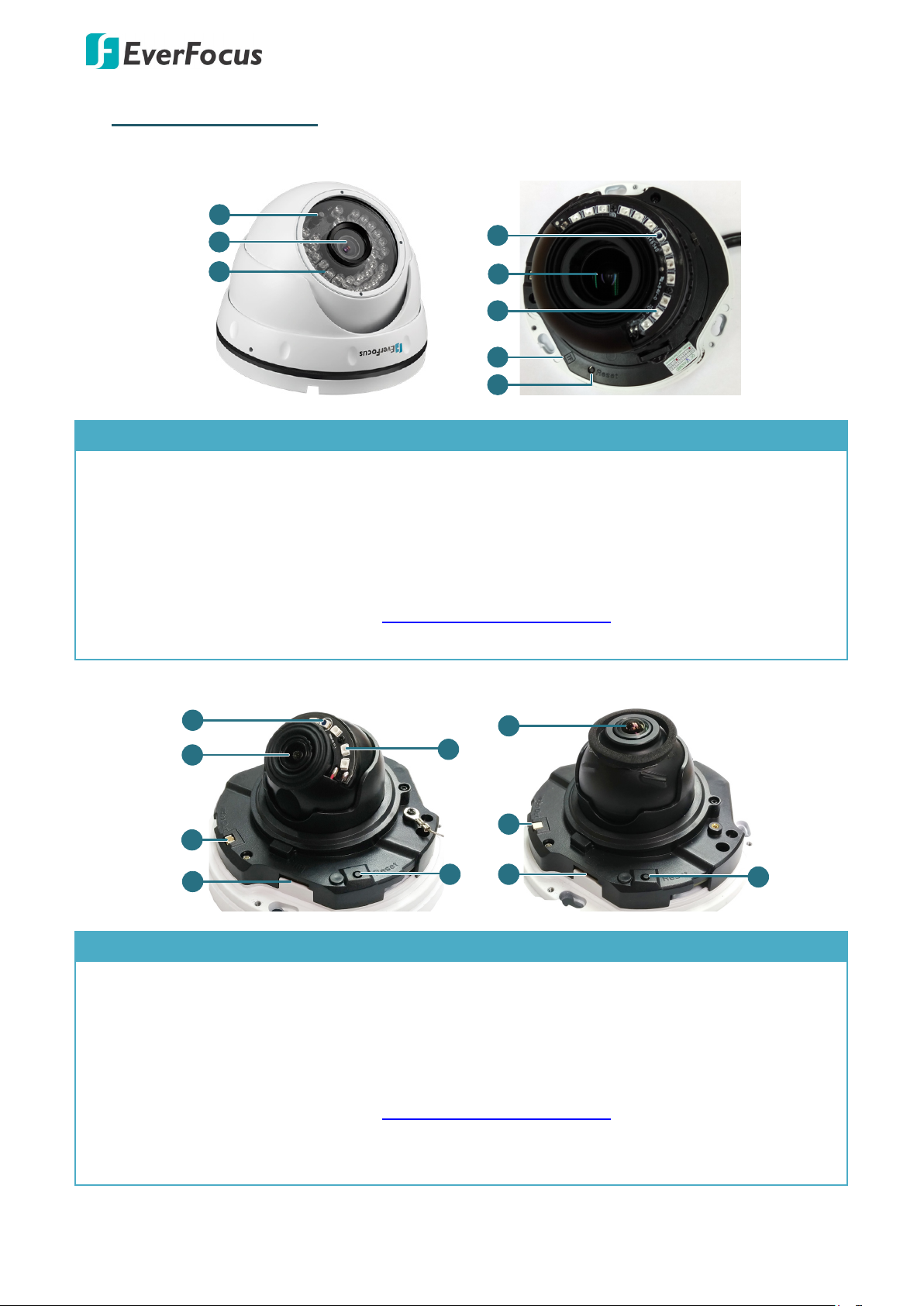
1. Physical Description
No. Item Name Descriptions
1 Light Sensor Detects lights.
2 Lens Lens.
3 IR LEDs IR LEDs for infrared illumination in night vision applications.
Insert a micro SD/SDHC/SDXC card. Please go to the web page of
4 Micro SD/SDHC/SDXC Slot
the IP camera to see the latest Storage Compatibility
List. http://www.everfocus.com.tw
5 Reset Button Press the button to restore the camera to factory default.
No. Item Name Descriptions
1 Light Sensor Detects lights.
2 Lens Lens.
3 Video Test Output Connects to a monitor.
4 Micro SD/SDHC/SDXC Slot
5 IR LEDs IR LEDs for infrared illumination in night vision applications.
6 Reset Button Press the button to restore the camera to factory default.
the IP camera to see the latest Storage Compatibility
List. http://www.everfocus.com.tw
1
Page 3
Value IP 288 / 368 / 468 Series
2
4
3
IR LED
Light Sensor
Lens
1
Sunshield
6
Micro SD/SDHC/SDXC Card Slot
5
Reset Button
Insert a micro SD/SDHC/SDXC card. Please go to the web page of
1
2
3
1
4
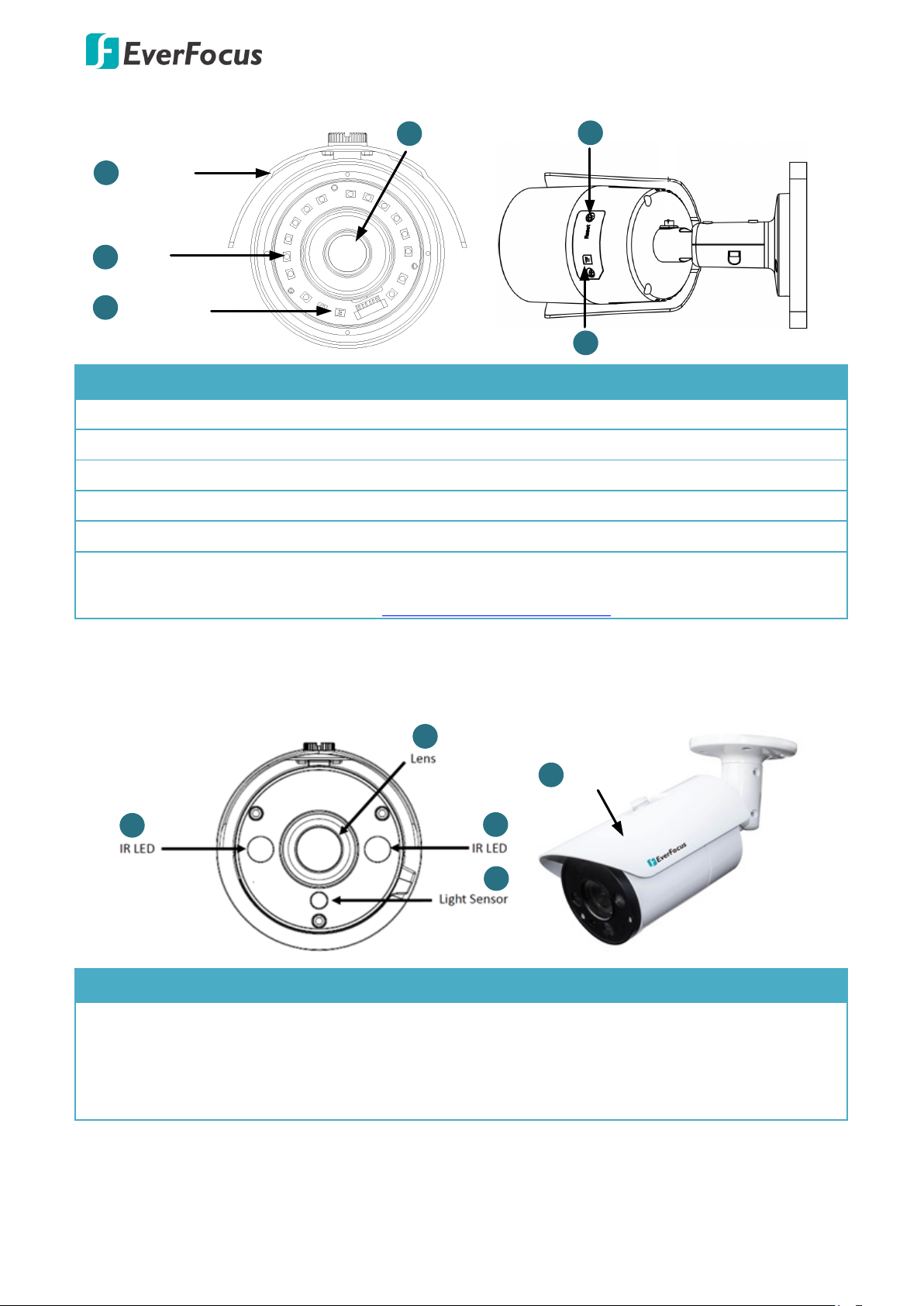
Sunshield
EZN288/368/468
No. Item Name Descriptions
1 Sunshield Protect the camera from the direct rays of the sun.
2 IR LEDs IR LEDs for infrared illumination in night vision applications.
3 Light Sensor Detects lights.
4 Lens Fixed lens.
5 Reset Button Press the button to restore the camera to factory default.
6 Micro SD/SDHC/SDXC Slot
the IP camera to see the latest Storage Compatibility
List. http://www.everfocus.com.tw
EZN288M/368M/468M
No. Item Name Descriptions
1 IR LEDs IR LEDs for infrared illumination in night vision applications.
2 Lens Motorized lens.
3 Light Sensor Detects lights.
4 Sunshield Protect the camera from the direct rays of the sun.
2
Page 4
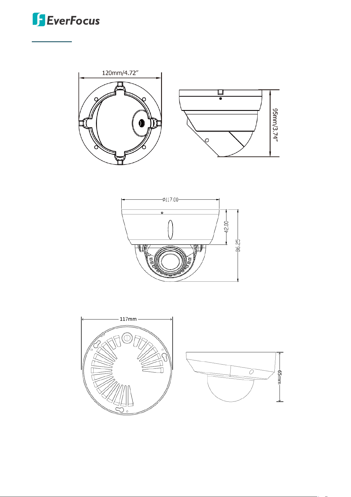
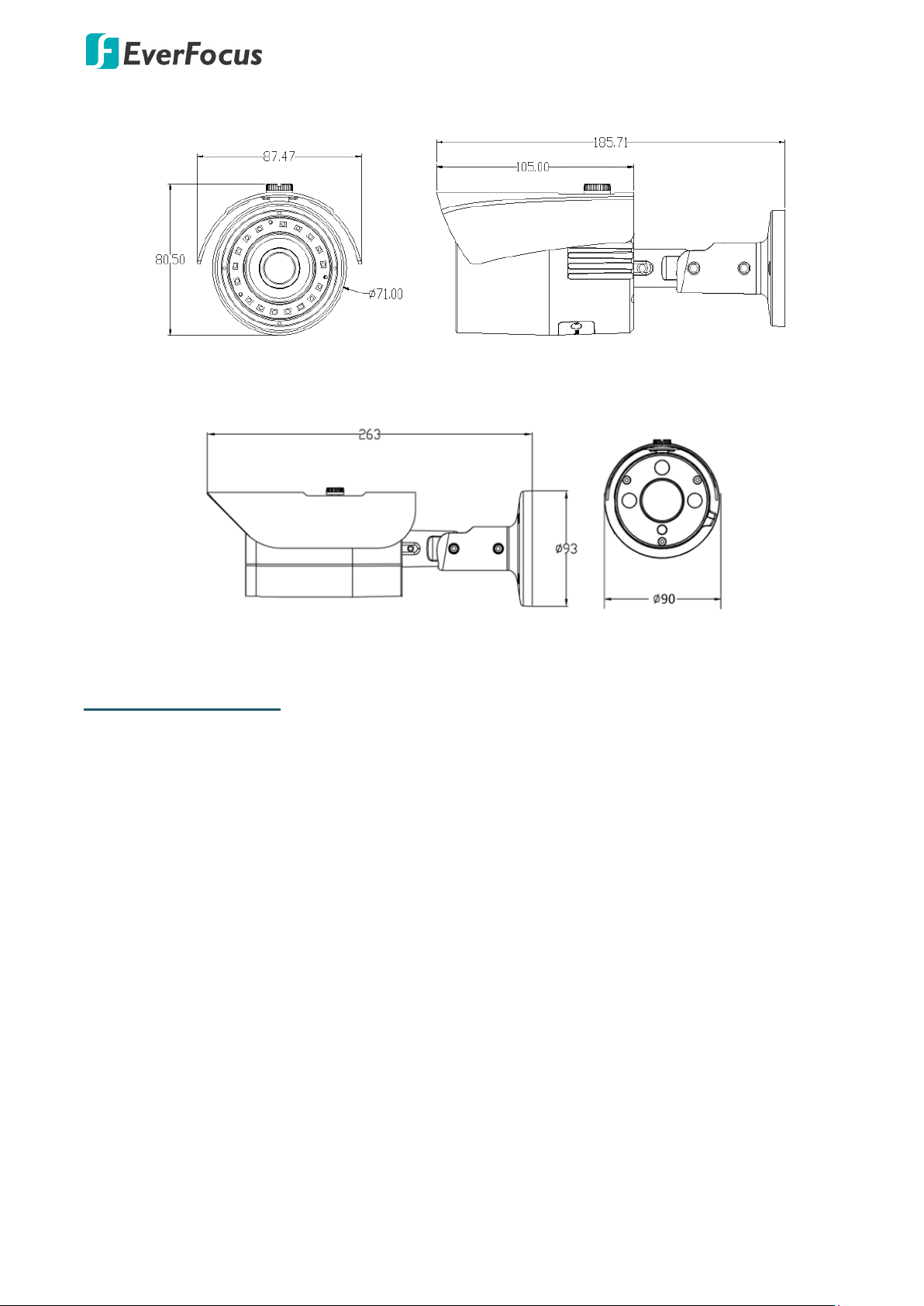
Dimensions
EBN288/368/468
EDN288M/368M/468M
Value IP 288 / 368 / 468 Series
EMN468/468W
3
Page 5
Value IP 288 / 368 / 468 Series
EZN288/368/468
EZN288M/368M/468M
System Requirements
Before installing, please check that your computer meets the following system requirements.
Operating System: Microsoft Windows XP / Vista (32-bit) / 7 (32-bit)
Microsoft Internet Explorer 11 or later, Chrome (Windows version 44 and earlier), Firefox
version 50 and earlier, EverFocus Browser
4
Page 6

Value IP 288 / 368 / 468 Series
Screw)
EverFocus office or agents for more information. Please also keep the shipping carton for possible
Packing List
Please check that there is no missing item in the package before installing.
No Item Name
1 Camera x 1 x 1 x 1 x 1 x 1
2 MAC Address Sticker x 2 x 2 x 2 x 2 x 2
Screw Anchor
3
(in conjunction with
Screw)
4 Screw x 4 x 3 x 3 x 3 x 4
Hexagon Wrench
5
(for adjusting camera
position)
Cable Gland Kit
6
(connect to the LAN/PoE
cable for waterproofing)
7 Set Screw x 3 - - - 8 Power Pigtail Cable x 1 x 1 x 1 x 1 x 1
EBN288/
368/468
x 4 x 3 x 3 x 3 x 4
x 1 - x 1 x 1 x 1
x 1 x 1 x 1 x 1 x 1
EDN288M/
368M/468M
EMN468/
468W
EZN288/
368/468
EZN288M/
368M/468M
Accessories Instruction
9
(for installation of Set
10 Software CD x 1 x 1 x 1 x 1 x 1
11 Quick Installation Guide x 1 x 1 x 1 x 1 x 1
Sticker
12
(Mounting Template)
13 Gasket - -
Note:
1. Equipment configurations and supplied accessories vary by country. Please consult your local
future use.
2. Contact the shipper if any items appear to have been damaged in the shipping process.
x 1 - - - -
x 1 x 1 x 1 x 1 x 1
x 1
(EMN468
W only)
- -
Optional Accessory
You can go to the product page on EverFocus’ website to check the related optional accessories.
www.everfocus.com.tw
5
Page 7
Value IP 288 / 368 / 468 Series
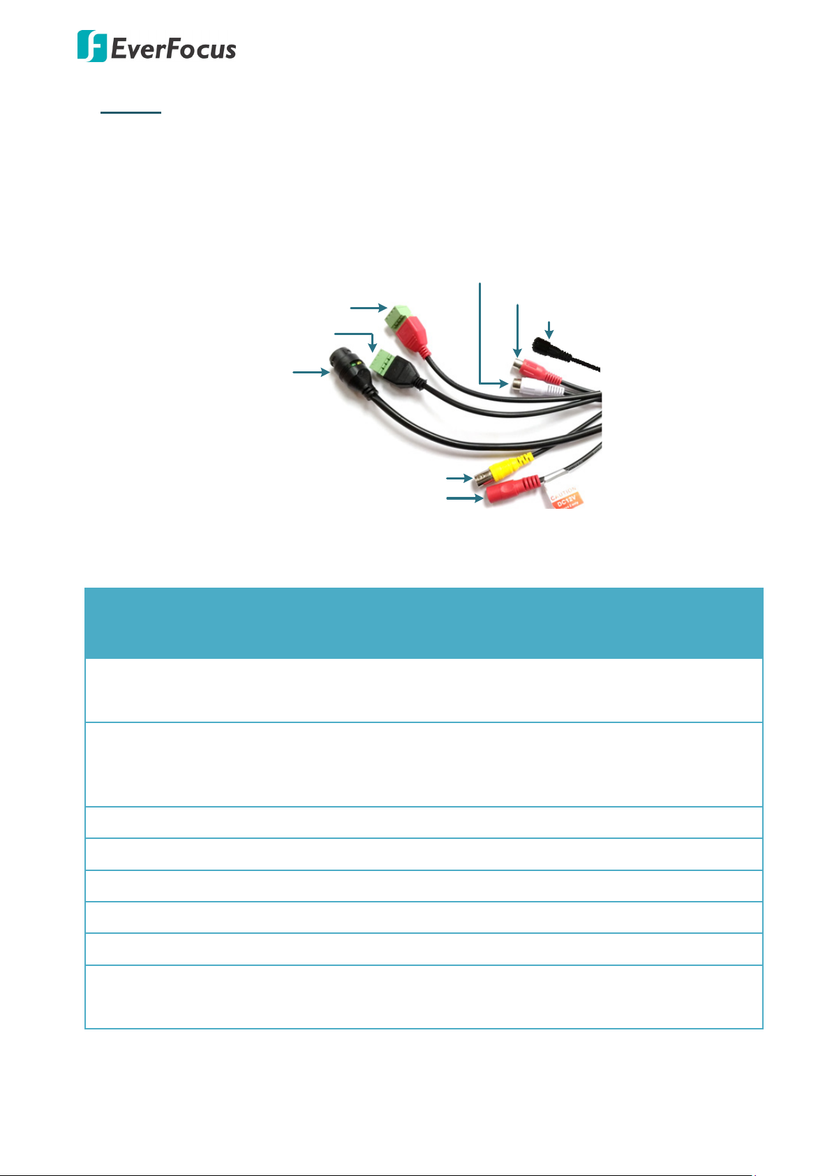
12VDC Input
LAN / PoE Cable
Audio Input (TRS Line-in) (Red)
Audio Output (TRS Line-out) (White)
Alarm Input (Black)
Reset Button
Alarm Output / RS-485 (Red)
Video Output (BNC) (Yellow)
Audio Out (White)
Yes
Yes - Yes
Yes
Video Out (BNC)
Yes
Yes - Yes
Yes
12VDC
Yes
Yes
Yes
Yes
2. Cables
For Standard models, the cables provide connections for Network, BNC output, power, audio input
/ output, RS-485 (reserved) and alarm inputs / output. A Reset Button is also provided. Note that
the audio-in / out cable features a line 3.5mm jack (TRS). Be sure to prepare microphones /
speakers with TRS connector (see TRS Connector image below). Also, microphones / speakers with
a (built-in) amplifier and external power supply are required.
EBN288/
EDN288M/
Cable
368/468
368M/468M
Alarm In (with
Yes Yes
Terminal Block)
Alarm Out /
RS-485 (reserved)
Yes Yes
(with Terminal
Audio In (Red) Yes Yes
EMN468/
468W
-
-
-
EZN288/
368/468
EZN288M/
368M/468M
Yes Yes
Yes Yes
Yes Yes
LAN/PoE Yes Yes
Reset Button (with
a dust-proof cap)
Yes -
Yes
Yes
-
6
Yes Yes
- Yes
Page 8
Value IP 288 / 368 / 468 Series
12VDC Input
LAN / PoE Cable
Reset Button
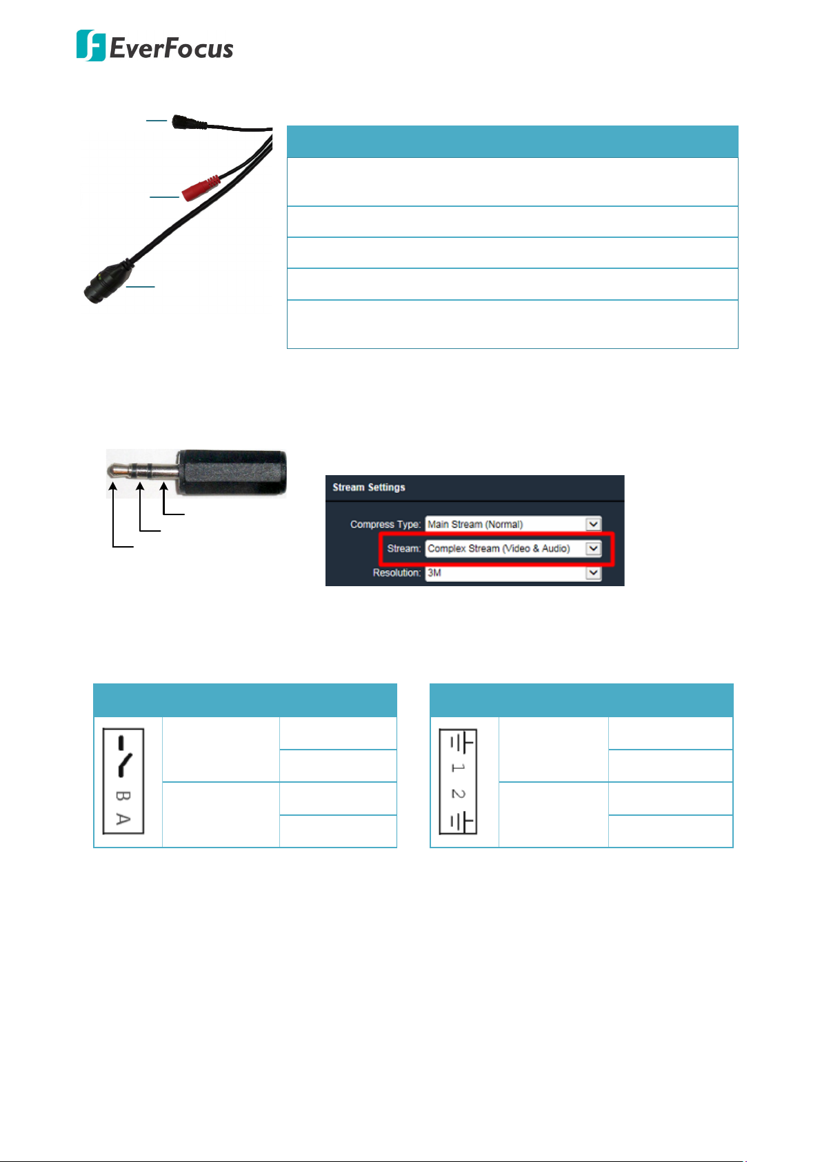
TRS Connector
Left Channel
(Tip)
Right Channel
(Ring)
Ground (Sleeve)
For Economic models, the cables provide connections for Network, power and Reset Button.
Cables of Economic Models
Model LAN/PoE 12VDC Reset Button
Audio Function
EBN288/368/468 Yes Yes
Yes (with a
dust-proof cap)
EDN288M/368M/468M Yes Yes -
EMN468/468W Yes Yes -
EZN288/368/468 Yes Yes -
Yes (with a
EZN288M/368M/468M Yes Yes
dust-proof cap)
To activate the Audio function, the Complex Stream must be
selected. See Stream in 7.2.1.2 Streaming Settings.
Pin Assignment
Alarm Output / RS-485 (reserved)
Alarm Output
RS-485
(reserved)
Reset Button
1. Reboot the camera:
When the camera is powered up, press the Reset Button will reboot the camera.
2. Restore the camera:
COM (-)
NO (+)
B (+)
A (-)
Alarm Input
GND (-)
Alarm In 1
Alarm In (+)
Alarm In (+)
Alarm In 2
GND (-)
Keep the Reset Button pressed, at the same time unplug the camera power then plug it back
again will return camera settings to the factory default values.
7
Page 9
Value IP 288 / 368 / 468 Series
3. Installation
This installation guide provides the basic instructions on installing an Value IP camera. For details,
please refer to the User’s Manual in the software CD.
3.1 Mounting and Wiring
EBN288/368/468
1. Before screwing the camera to the wall, stick the Sticker on the wall / ceiling to mark the
position for installation. Drill four holes on the wall / ceiling according to the supplied Sticker
and push the supplied four Screw Anchors into the four holes on the wall / ceiling. Drill
another hole in the middle of the Sticker if you wish to run the wires into the wall / ceiling.
2. Twist the Outer Housing counterclockwise and then remove the Outer Housing from the
camera base.
3. Place the camera base on the wall / ceiling and run the cable through the camera base first.
4. Tread the cables:
a. From the side cut of the camera base
8
Page 10

Value IP 288 / 368 / 468 Series
Wall or
Ceiling
b. Through the wall / ceiling: run the cables through the hole on the wall / ceiling.
5. Use the supplied four Screws to screw the camera base to the ceiling / wall.
6. Adjust the camera angle and twist back the Outer Housing simultaneously.
7. Optionally screw back the Set Screw by using the supplied Hexagon Wrench to prevent
uninstallation.
8. Connect the LAN / PoE cable to the camera.
a. Remove the Screw Cap from the Cable Gland.
9
Page 11

Value IP 288 / 368 / 468 Series
Power
Adapter
Pigtail
Power Cable
RJ
-
45
Connector
or
Power Adapter
Wall or Ceiling
Sticker
Anchors
Screws
b. Insert a RJ-45 network cable (without the RJ-45 connector on the one end) through the
Cable Gland and Screw Cap.
c. Place the Waterproof Ring into the LAN / PoE cable. Connect the RJ-45 cable to the RJ-45
Connector Cable. Tightly screw the Cable Gland and Screw Cap to the RJ-45 Connector
Cable.
9. Optionally connect the camera to the 12VDC power source using the supplied Power
Adapter Pigtail or a power adapter.
EDN288M/368M/468M
1. Before screwing the camera to the wall, stick the Sticker on the wall / ceiling to mark the
position for installation. According to the supplied Sticker, drill three screw-depth holes on
the wall / ceiling, and then drill a through-wall hole for wiring the camera cables. Push the
supplied three Screw Anchors into the three holes on the wall / ceiling.
10
Page 12

Value IP 288 / 368 / 468 Series
2. Unscrew the camera cover and screw the camera base to the ceiling / wall by using the
supplied Screws.
3. Optionally insert the micro SDHC / SDXC card. Please refer to 3.2 Inserting a micro SD Card.
4. Connect the LAN / PoE cable to the camera.
a. Remove the Screw Cap from the Cable Gland.
b. Insert a RJ-45 network cable (without the RJ-45 connector on the one end) through the
Cable Gland and Screw Cap.
c. Place the Waterproof Ring into the LAN / PoE cable. Connect the RJ-45 cable to the RJ-45
Connector Cable. Tightly screw the Cable Gland and Screw Cap to the RJ-45 Connector
Cable.
11
Page 13

Value IP 288 / 368 / 468 Series
Power Adapter Pigtail
Power Cable
RJ-45 Connector
or
Power Adapter
75°
75°
3-
Axis
Bracket
30°
30°
Rotation screw
5. Optionally connect the camera to the 12VDC power source using the supplied Power
Adapter Pigtail or a power adapter.
6. Access the camera live view. See 5. Accessing the Camera. Or using a video Test-Out cable to
connect a monitor to the camera for setting image aim and focus.
7. To adjust camera angles.
Pan Adjustment: Simply turn left / right of the 3-Axis bracket by 75° to the desired position.
Rotational Adjustment: Loosen the rotate screw and rotate the camera left / right to the
desired position, then tighten the rotate screw. Due to the internal connector design, it is
recommended not to rotate the camera more than 30°.
12
Page 14

Value IP 288 / 368 / 468 Series
75°
Tilt screw
Tilt Adjustment: Loosen the two tilt screws and adjust the angle by 75° to the desired
position, then tighten the tilt screw.
8. Secure the cover back to the camera.
EMN468/468W
1. Before screwing the camera onto the surface, stick the Sticker onto the surface to mark the
position for installation. According to the supplied Sticker, drill three holes on the surface,
and optionally drill a through-out hole for wiring the camera cables. Push the supplied three
Screw Anchors into the three holes on the surface.
2. Unscrew the camera cover and screw the camera base to the surface by using the supplied
Screws. Note that for EMN468W, place the supplied Gasket between the camera base and
the surface; and then screw the camera base to the surface with the Gasket in the middle.
3. Connect the LAN / PoE cable to the camera.
a. Remove the Screw Cap from the Cable Gland.
13
Page 15

Value IP 288 / 368 / 468 Series
Power Adapter Pigtail
Power Cable
RJ-45 Connector
or
Power Adapter
b. Insert a RJ-45 network cable (without the RJ-45 connector on the one end) through the
Cable Gland and Screw Cap.
c. Place the Waterproof Ring into the LAN / PoE cable. Connect the RJ-45 cable to the RJ-45
Connector Cable. Tightly screw the Cable Gland and Screw Cap to the RJ-45 Connector
Cable.
4. Optionally connect the camera to the 12VDC power source using the supplied Power
Adapter Pigtail or a power adapter.
5. Access the camera live view. See 5. Accessing the Camera. Or using a video Test-Out cable to
connect a monitor to the Video Test Output on the camera for setting camera angles.
14
Page 16

Value IP 288 / 368 / 468 Series
175
°
175°
25~90°
EZN288M/368M/468M
6. To adjust camera angles.
Pan Adjustment: Simply turn left / right of the camera by 175° each side to the desired
position.
Tilt Adjustment: Adjust the tilt angle between 25° and 90°.
7. Secure the cover back to the camera.
EZN288/368/468 & EZN288M/368M/468M
1. Before screwing the camera to the wall, stick the Sticker on the wall / ceiling to mark the
screw position. Drill three (EZN288/368/468) or four (EZN288M/368M/468M) holes on the
wall / ceiling according to the supplied Sticker and push the supplied Anchors into the holes
on the wall / ceiling. Drill another hole in the middle of the Sticker if you wish to run the
wires into the wall / ceiling.
EZN288/368/468
15
Page 17

Value IP 288 / 368 / 468 Series
Wire the cables from the side of the camera
Wire the cables through the wall
2. You can wire the cables from the side of the camera or through the wall.
3. Place the camera’s base against the anchoring surface so that the holes line up. Screw the
camera to the wall / ceiling using the supplied Screws.
4. Optionally insert a micro SD / SDHC / SDXC card into the card slot. Please refer to 3.2
Inserting a micro SD Card.
5. Connect the LAN / PoE cable to the camera.
a. Remove the Screw Cap from the Cable Gland.
b. Insert a RJ-45 network cable (without the RJ-45 connector on the one end) through the
Cable Gland and Screw Cap.
c. Place the Waterproof Ring into the LAN / PoE cable. Connect the RJ-45 cable to the RJ-45
Connector Cable. Tightly screw the Cable Gland and Screw Cap to the RJ-45 Connector
Cable.
16
Page 18

Value IP 288 / 368 / 468 Series
Power
Adapter Pigtail
Power Cable
RJ-45 Connector
or
Power Adapter
Set Screw
Camera
Base
360°
Set Screw
Camera Base
360°
6. Optionally connect the camera to the 12VDC power source using the supplied Power
Adapter Pigtail or a power adapter.
7. Access the camera live view. See 5. Accessing the Camera. Or connect a handheld test
monitor to the CVBS wire on the Cable Assembly for adjusting viewing angles.
8. To adjust the camera angles:
Pan Adjustment: Loosen the Set Screw using the supplied Hexagon Wrench. Rotate the
camera by 360° to the desired position and screw the Set Screw until it locks against the
Camera Base.
EZN288/368/468 EZN288M/368M/468M
17
Page 19

Value IP 288 / 368 / 468 Series
Set Screw
90°
Set Screw
90
°
Set Screw
Set Screw
Tilt Adjustment: Loosen the Set Screw using the provided Hexagon Wrench and adjust the
angle by 90°.
EZN288/368/468 EZN288M/368M/468M
Rotational Adjustment: Loosen the Screw using the provided Hexagon Wrench and rotate
the camera by 360°.
EZN288/368/468 EZN288M/368M/468M
Note:
1. Before start operating the IP camera, please make sure the camera date and time are
correct. To configure the camera date/time, go to System > Date/Time setting page on
Web UI.
2. By default, the system will automatically adjust the IR LED strength according to the
scene, so please avoid IR reflection when installing the camera to prevent out-of-focus at
night.
3. Under Auto focus mode, if the camera does not focus after switching the Day/Night
mode, it is recommended to switch the focus mode to Manual and adjust focus manually.
18
Page 20

Value IP 288 / 368 / 468 Series
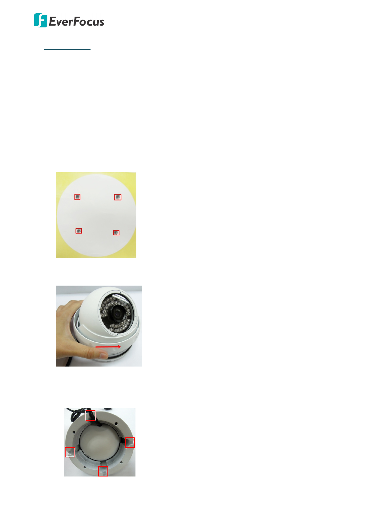
3.2 Inserting a Micro SD Card
You can optionally insert a micro SD card to the card slot on the camera module for recording
videos.
EDN288M/368M/468M
1. Unscrew and then remove the camera cover.
2. Insert a micro SD card into the card slot.
EMN468/468W
1. Unscrew and then remove the camera cover.
2. Insert a micro SD card into the card slot.
EZN288/368/468
1. Open the cover on the bottom of the camera by loosening the screws.
2. Insert a micro SD card into the card slot.
19
Page 21

Value IP 288 / 368 / 468 Series
Set Screw
EZN288M/368M/468M
1. Loosen the two set screws on the bracket.
2. Loosen the three screws on the rear housing. Rotate and then remove the rear housing.
3. Loosen the four screws on the IPC board.
20
Page 22

Value IP 288 / 368 / 468 Series
Water-proof ring
Desiccant bag
4. Insert a micro SD card into the card slot.
5. Put the water-proof ring on the groove that near the edge of the housing. Place the
desiccant bag beside the IPC board.
6. Screw back the IPC board, secure the rear housing back to the front housing and tighten
the set screws on the bracket.
Note: Please make sure you wear the antistatic gloves or antistatic wrist strap when installing
the Micro SD card to protect the device from damage.
21
Page 23

Value IP 288 / 368 / 468 Series
4. Accessing the Camera
You can look up the IP address and access the Web interface of the IP camera using the IP Utility
(IPU) program, which is included in the software CD. The IP Utility can also be downloaded from
EverFocus’ Website: http://www.everfocus.com.tw/HQ/Support/DownloadCenter_p1.aspx
(Support > Download Center > Keyword Search: IP Utility). Please connect the IP camera on the
same LAN of your computer.
1. Save IP Utility Setup .exe in your computer. Double click the .exe file and follow the
on-screen instructions to install the IP Utility.
2. Click the Finish button, the IP Utility will be automatically launched to search the IP devices
connected on the same LAN.
3. To access the Live View window, double click the IP address of the desired device, the login
window pops up. Type the user ID and password to log in. By default, the user ID is user1
and the password is 11111111
22
Page 24

Value IP 288 / 368 / 468 Series
4. Click Login, the Live View window appears.
Note:
1. To enable Remote Live View, Firmware Upgrade and ActiveX Prompt on Internet
Explorer, some settings have to be complete. Please refer to 5.2 Settings for Microsoft
Internet Explorer.
2. The default IP mode of the IP camera is DHCP. However, if there is no dynamic IP
address assigned to the device, its IP will switch to 192.168.0.10.
5. To optionally configure the Machine Name, IP Address, IP Type or Port Number using the
IPU:
a. Log in the camera by checking the desired model and then click the Log in icon.
The Log in dialog box appears.
b. Type the Username and Password. Click the OK button, the Login status displays.
Note:
1. The default user ID is user1 and the default password is 11111111.
2. If you select more than one camera that has the same user ID / password, you will
be able to log in several cameras at once.
c. Right click the column to configure the settings. Click the Apply Changes button to
apply and save the settings.
23
Page 25

Value IP 288 / 368 / 468 Series
1
2
3
1
2
3
To set up a static IP:
By default, EverFocus’ IP cameras are set up with DHCP. To change the IP setting to static IP, select
Static IP from IP Type drop-down list and set up the desired IP Address, for example,
192.168.31.67.
Please also set up the Subnet Mask and Gateway. Click the Apply Changes button to apply and
save the settings.
To show the Subnet Mask and Gateway items on the title bar, right click the title bar to display the
Customize Columns window, select Subnet Mask and Gateway and then click OK.
24
Page 26

Value IP 288 / 368 / 468 Series
Cat 5
Straight Through Cable
High-speed modem
Internet
Cat 5
Right: Pinout of a crossed-
over cable.
5. Network Connections
You can use one of the methods below to connect the camera to the network.
Direct High-Speed Connection
In a Direct High-Speed Connection, the camera connects directly to a modem without the need for a
router. You need to set the static or dynamic WAN IP address assigned by your ISP (Internet Service
Provider) in the camera’s configuration web pages. To access the camera, just type
“http://xxx.xxx.xxx.xxx”, where xxx.xxx.xxx.xxx is the IP address given by your ISP. If you have a
dynamic IP address, this connection may require that you use DDNS for a reliable connection.
Please refer to DDNS Settings in 7.1.1 Network in the User’s Manual.
One-to-One Connection (Directly from PC to IP Camera)
You can connect directly without using a switch, router or modem. However, only the PC connected
to the camera will be able to view the IP camera. You will also have to manually assign a compatible
IP address to both the computer and the IP camera. Unless the PC has another network connection,
the IP camera will be the only network device visible to the PC. See the diagram below:
Router or LAN Connection
This is the most common connection in which the IP camera is connected to a router and allows
multiple users on and off site to see the IP camera on a LAN/WAN (Internet). The camera must be
assigned an IP address that is compatible with its LAN. By setting up port forwarding on the router,
you can remotely access the cameras from outside of the LAN via the Internet. To remotely access
the Web interface of the IP camera, please refer to DDNS Settings in 7.1.1 Network in the User’s
Manual. To set up port forwarding, please consult the manual of the router.
25
Page 27

Value IP 288 / 368 / 468 Series
High-speed modem
Internet
Straight-through LAN patch cable
Router
Cat 5 Straight Through Cable
Left:
Pinout of a straight-
through cable.
6. Upgrading Firmware
You can upgrade the Firmware using the IP Utility software included in the software CD. The IP
Utility can also be downloaded from EverFocus’
Website: http://www.everfocus.com.tw/HQ/Support/DownloadCenter_p1.aspx (Support >
Download Center > Keyword Search: IP Utility). Please connect the IP camera on the same LAN of
your computer.
1. Install and then start the IPU program , the following IPU window appears. The IPU will
automatically search the IP devices connected in the LAN.
2. Log in the camera by checking the desired model and then click the Log in icon. The Log
in dialog box appears.
26
Page 28

Value IP 288 / 368 / 468 Series
3. Type the Username and Password. Click the OK button, the Login status displays.
Note:
1. The default user ID is user1 and the default password is 11111111
2. If you select more than one camera that has the same user ID / password, you will be
able to log in several cameras at once.
3. Up to 10 cameras can be simultaneously upgraded to the latest firmware. If you connect
the cameras to a PoE switch, please make sure the Power Consumption of the PoE
switch is sufficient.
4. Click the Upgrade Firmware button , a browsing window appears.
5. Select the firmware file (.evb) and then click Open. The IPU will automatically upgrade the
firmware. The camera will reboot once the upgrade process is complete.
27
Page 29

EverFocus Taiwan:
EverFocus Europe - Germany:
EverFocus China - Beijing:
EverFocus China - Shenzhen:
EverFocus USA - California:
EverFocus Japan:
Your EverFocus product is designed
Ihr EverFocus Produkt wurde entwickelt
EverFocus Electronics Corp.
12F-1, No.79, Sec. 1, Shin-Tai Wu Road,
Hsi-Chih, New Taipe i City, Taiwan
TEL: +886 2 2698 2334
FAX: +886 2 2698 3943
www.everfocus.com.tw
marketing@everfocus.com.tw
Room 609, Technology Trade Building,
Shangdi Information Industry Base,
Haidian District, Beijing 100085, China
TEL: +86 10 6297 3336~39
FAX: +86 10 6297 1423
www.everfocus.com.cn
marketing@everfocus.com.cn
1801 Highland Avenue, Unit A, Duarte,
CA 91010, USA
TEL: +1 626 844 8888
FAX: +1 626 844 8838
www.everfocus.com
sales@everfocus.com
Albert-Einstein-Strasse 1, D-46446
Emmerich, Germany
TEL: +49 2822 93940
FAX: +49 2822 939495
www.everfocus.de
sales@everfocus.de
3F,Building 7,Longcheng Industrial
Park,No.440,Longguan Road, Dalang Street,
Longhua, Shenzhen, Guangdong, China
TEL: +86 755 2765 1313
FAX: +86 755 2765 0337
www.everfocus.com.cn
marketing@everfocus.com.cn
3F, Kuramochi, Building II
2-2-3 Koto-Bashi, Sumida-Ku,
Tokyo, 130-0022, Japan
TEL: +81 3 5625 8188
FAX: +81 3 5625 8189
www.everfocus.co.jp
info@everfocus.co.jp
and manufactured with high qua lity
materials and compone nts which can
be recycled and reused.
This symbol means that electrical and
electronic equipment, at their
end-of-life, should be disposed of
separately from your household waste.
Please, dispose of this equipment at
your local community waste
collection/recycling centre.
In the European Union there are
separate collection systems for used
electrical and electro nic product.
Please, help us to conserve the
environment we live in!
und hergestellt mit qualitativ
hochwertigen Materia lien und
Komponenten, die recycelt und wieder
verwendet werden können.
Dieses Symbol bedeutet, dass
elektrische und elektronische Geräte am
Ende ihrer Nutzungsdauer vom
Hausmüll getrennt entsorgt werden
sollen.
Bitte entsorgen Sie dieses Gerät bei
Ihrer örtlichen kommuna len
Sammelstelle oder im Recycling Centre.
Helfen Sie uns bitte, die Umwelt zu
erhalten, in der wir leben
!
 Loading...