

EverFocus ECOR Series, ECOR 4D Instruction Manual
Instruction Manual
E
ECC
O
O
R
RSSeerriieess
D
DVV
R
R

EVERFOCUS ELECTRO N I C S CORPORATI O N
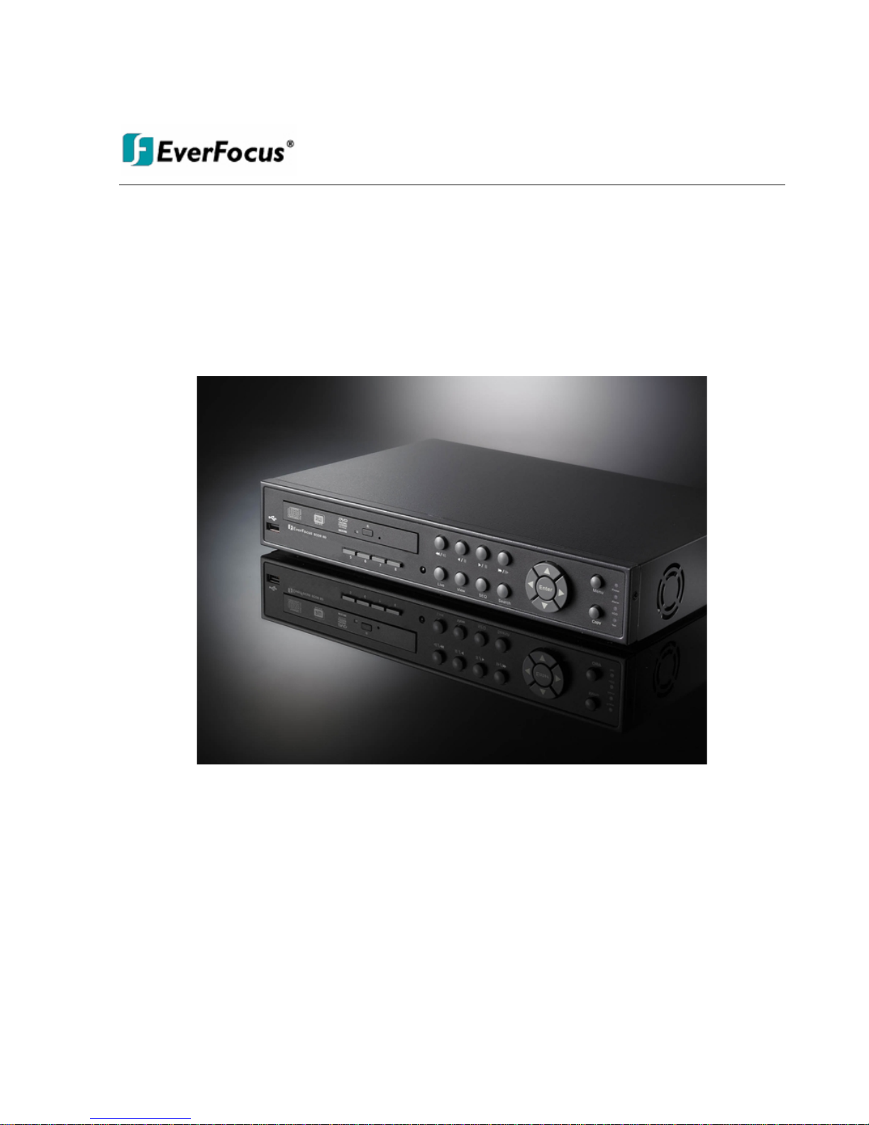
ECORSeries DVR
InstructionManual
2008 EverFocus Electronics Corp
www.everfocus.com
All rights reserved. No part of the contents of this manual may be reproduced or transmitted in any form or by
any means without written permission of the Everfocus Electronics Corporation.
Release Date: May 2009
Windows is a registered trademark of the Microsoft Corporation.
QuickTime is a registered trademark of the Apple Computer, Inc.
Linksys is a registered trademark of the Linksys Corporation.
D-Link is a registered trademark of the D-Link Corporation.
Other product and company names mentioned herein may be the trademarks of their respective owners.
ii
Safety Precautions
• To avoid any damage, please consider the following safety warnings:
• Never place the recorder near to heaters, furnaces, other heat sources or under direct solar irradiation.
• Operate the device only in locations providing the tolerable operatingtemperature range
0°C~40°C/32°F ~ +104°F.
• Make sure that the device‘s ventilation slots are not covered or sheeted.
• For cleaning, make sure the device is plugged off and only use a damp cloth without acid detergent.
• Install the device only in dry and dustproof surroundings. Protect the device against any liquid‘s
penetration.
• Avoid the penetration of any artifacts, e.g. through ventilation slots.
• Do not attempt to disassemble the appliance. To prevent electric shock, do not remove screws or
covers. There are no user-serviceable parts inside. Contact qualified service personnel for maintenance.
Handle the appliance with care. Do not strike or shake, as this may damage the appliance.
• Do not operate appliance with other than specified power supplies. The input power source of the power
supply is 12 VDC with external power supply 100 ~ 240 VAC.
• Avoid any affection of the device through vibrations or mechanical shock at the recorder‘s installation
location.
• Avoid to power off DVR during playback or recording operation.
ATTENTION! This is a class A product which may cause radio interference in a domestic environment; in
this case, the user may be urged to take adequate measures.
Federal Communication Commission Interference Statement
This equipment has been tested and found to comply with the limits for a Class B digital device, pursuant to
Part 15 of the FCC Rules. These limits are designed to provide reasonable protection against harmful
interference in a residential installation. This equipment generates, uses and can radiate radio frequency
energy and, if not installed and used in accordance with the instructions, may cause harmful interference to
radio communications. However, there is no guarantee that interference will not occur in a particular
installation. If this equipment does cause harmful interference to radio or television reception, which can be
determined by turning the equipment off and on, the user is encouraged to try to correct the interference by
one of the following measures :
•Reorient or relocate the receiving antenna.
•Increase the separation between the equipment and receiver.
•Connect the equipment into an outlet on a circuit different from that to which the receiver is connected.
•Consult the dealer or an experienced radio/TV technician for help.
FCC Caution: Any changes or modifications not expressly approved by the party responsible for compliance
could void the users’ authority to operate this equipment.

iii
This Product is RoHS compliant.
WEEE
The information in this manual was current upon publication. The manufacturer reserves the right to revise and improve his products.
Therefore, all specifications are subject to change without prior notice. Misprints reserved.
Please read this manual carefully before installing and using this unit. Be sure to keep it handy for later reference.

iv
TABLE OF CONTENTS
1 PRODUCT OVERVIEW..................................................................................................... 1
1.1 FEATURES...........................................................................................................................1
1.2 PACKAGE CONTENTS..........................................................................................................2
1.3 SPECIFICATIONS..................................................................................................................3
1.4 FRONT PANEL.....................................................................................................................5
1.5 BACK PANEL ......................................................................................................................7
2 INSTALLATION..................................................................................................................9
2.1 VIDEO CONNECTIONS.........................................................................................................9
2.2 AUDIO CONNECTION INSTALLATION ..................................................................................9
2.3 ALARM INPUT / OUTPUT INSTALLATION...........................................................................10
2.4 NETWORK CONNECTION...................................................................................................11
2.4.1 Direct PC Connection through Crossover Network Cable................................................................... 11
2.4.2 Network Connection through Patch Cable........................................................................................... 11
2.4.3 Network System Requirements.............................................................................................................. 12
2.5 SPEED DOME INSTALLATION............................................................................................12
2.6 FINAL INSTALL PROCESS ..................................................................................................13
3 MOUSE AND FRONT PANEL OPERATION ...............................................................14
3.1 GENERAL USBMOUSE OPERATION .................................................................................14
3.1.1 OSD Root Menu.................................................................................................................................... 14
3.1.2 Operation in Configuration Menu........................................................................................................ 15
3.1.3 Component Options.............................................................................................................................. 15
3.2 GENERAL FRONT PANEL OPERATION ...............................................................................17
3.2.1 Front Panel Key Review....................................................................................................................... 17
3.2.2 Operation in Configuration Menu........................................................................................................ 17
3.2.3 Component Options.............................................................................................................................. 18
4 GENERAL DVR OPERATIONS......................................................................................19
4.1 RECORD............................................................................................................................19
4.2 LOGIN...............................................................................................................................19
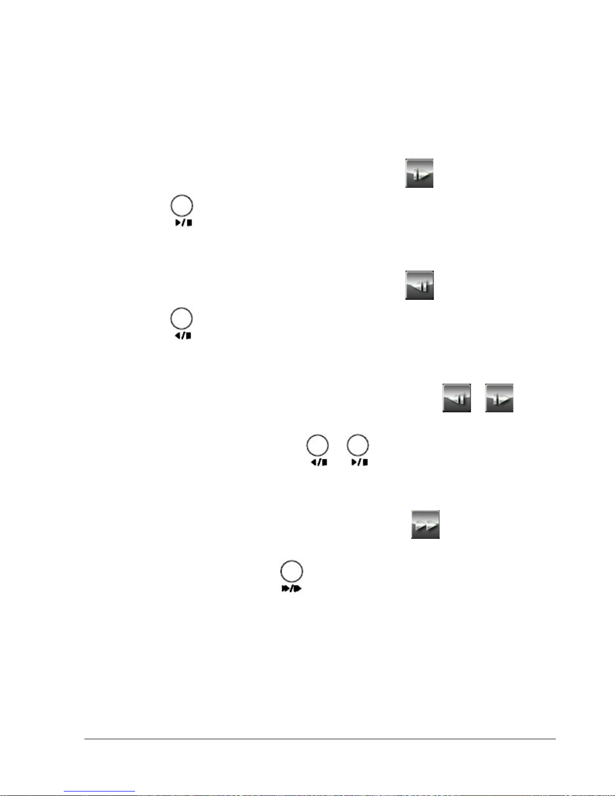
4.3 PLAYBACK OPERATION ....................................................................................................21
4.3.1 Playback............................................................................................................................................... 21
4.3.2 Reverse playback.................................................................................................................................. 21
4.3.3 Pause.................................................................................................................................................... 21
4.3.4 Fast forward......................................................................................................................................... 21
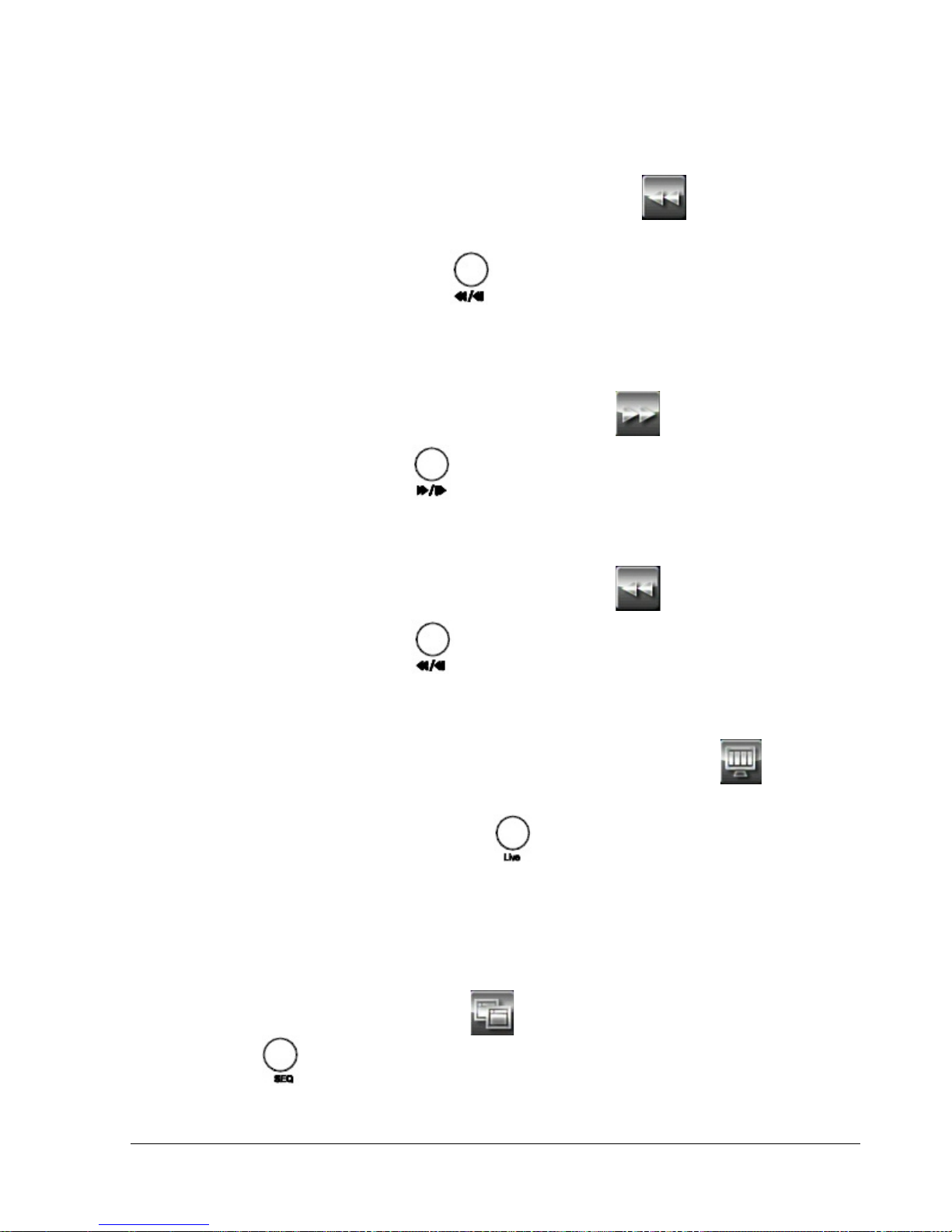
4.3.5 Fast backward...................................................................................................................................... 22
4.3.6 Step forward ......................................................................................................................................... 22
4.3.7 Step backward ...................................................................................................................................... 22
4.3.8 Stop playback ....................................................................................................................................... 22
4.4 START SEQUENCE.............................................................................................................22
4.5 LAYOUT CHANGE.............................................................................................................23

v
4.5.1 Layout Change ..................................................................................................................................... 23
4.5.2 Bring to Full Screen Mode ................................................................................................................... 23
4.6 QUICK MENU.................................................................................................................... 24
4.6.1 Triplex Operation................................................................................................................................. 24
4.6.2 Change Camera Order......................................................................................................................... 24
4.7 COPY ................................................................................................................................25
4.7.1 Standard Copy...................................................................................................................................... 25
4.7.2 Quick Copy........................................................................................................................................... 26
4.8 SEARCH ............................................................................................................................26
4.8.1 Time Search.......................................................................................................................................... 27
4.8.2 Event Search......................................................................................................................................... 27
4.8.3 Smart Motion Search............................................................................................................................ 28
4.8.4 Search Result........................................................................................................................................ 29
4.9 LOGOUT............................................................................................................................ 31
5 DVR CONFIGURATION..................................................................................................32
5.1 OSD SETTING MENU........................................................................................................32
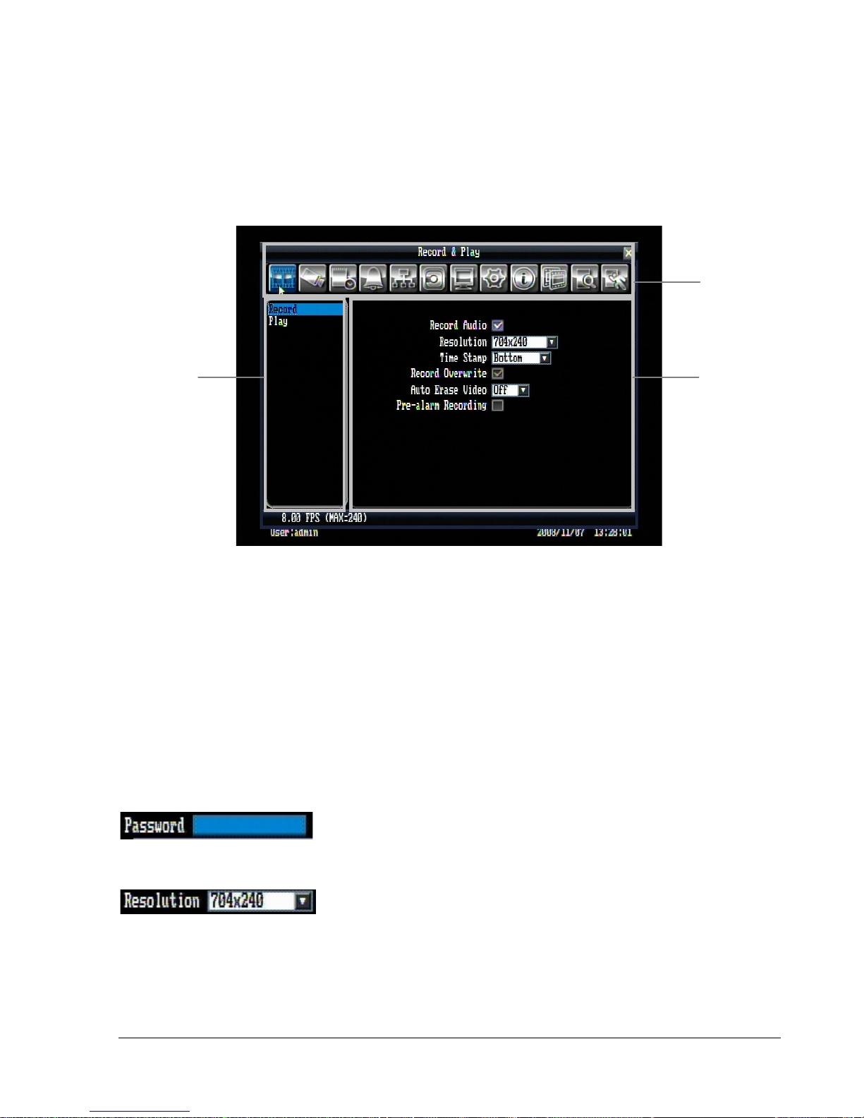
5.2 RECORD &PLAY SETTING................................................................................................32
5.2.1 Record .................................................................................................................................................. 32
5.2.2 Play....................................................................................................................................................... 33
5.3 CAMERA SETTING.............................................................................................................34
5.3.1 Basic Setting......................................................................................................................................... 34
5.3.2 Video Adjust ......................................................................................................................................... 36
5.3.3 Motion .................................................................................................................................................. 37
5.3.4 Video Loss ............................................................................................................................................ 39
5.4 SCHEDULE SETTING..........................................................................................................40
5.5 ALARM &EVENT SETTING ...............................................................................................42
5.5.1 Alarm.................................................................................................................................................... 42
5.5.2 Event..................................................................................................................................................... 43
5.6 NETWORK SETTING ..........................................................................................................48
5.6.1 LAN....................................................................................................................................................... 48
5.6.2 EMAIL.................................................................................................................................................. 49
5.6.3 DDNS ................................................................................................................................................... 50
5.7 DISK SETTING...................................................................................................................51
5.8 DISPLAY SETTING.............................................................................................................52
5.8.1 Monitor OSD........................................................................................................................................ 52
5.8.2 Main M/T SEQ...................................................................................................................................... 53
5.9 SYSTEM SETTING..............................................................................................................54
5.9.1 Date/Time............................................................................................................................................. 54
5.9.2 Daylight Saving.................................................................................................................................... 55
5.9.3 User...................................................................................................................................................... 56
5.9.4 Security................................................................................................................................................. 57
5.9.5 I/O Control........................................................................................................................................... 58
5.9.6 Firmware & Misc................................................................................................................................. 59
5.10 INFORMATION SETTING.................................................................................................. 60
5.10.1 System................................................................................................................................................... 60
5.10.2 Log........................................................................................................................................................ 61
6 NETWORKING OVERVIEW..........................................................................................63

vi
6.1 INTRODUCTION TO TCP/IP...............................................................................................63
6.2 SUBNET MASKS................................................................................................................ 63
6.3 GATEWAY ADDRESS.........................................................................................................63
6.4 VIRTUAL PORTS................................................................................................................64
6.5 PRE-INSTALLATION ..........................................................................................................64
6.6 WHAT IS YOUR NETWORK SETUP?....................................................................................65
6.7 SIMPLE ONE TO ONE CONNECTION...................................................................................66
6.8 DIRECT HIGH SPEED MODEM CONNECTION .....................................................................71
6.9 ROUTER OR LANCONNECTION........................................................................................73
7 REMOTE OPERATION FROM BROWSER................................................................. 76
7.1 CONNECTING TO ECOR....................................................................................................76
7.2 IEBROWSERSETTING&ACTIVEXCONTROLINSTALLATION................................................... 77
7.2.1 Installing ActiveX controls ................................................................................................................... 77
7.2.2 Enabling ActiveX Controls................................................................................................................... 79
7.3 REMOTE LIVE VIEW .........................................................................................................82
7.4 REMOTE PTZCONTROL ...................................................................................................83
7.5 REMOTE PLAYBACK .........................................................................................................84
8 EVERFOCUS DDNS SETUP............................................................................................85
9 LINKSYS & D-LINK PORT FORWARDING...............................................................86
9.1 LINKSYS PORT FORWARDING ...........................................................................................86
9.2 D-LINK PORT FORWARDING.............................................................................................88
10 TROUBLESHOOTING ..................................................................................................91
APPENDIX A: TIMING OF ALARM MODES......................................................................92
APPENDIX B: CONTROL PROTOCOL................................................................................96

1
1 Product Overview
The ECOR series DVR is based on MPEG-4 compression technology, resulting in enhanced recording
capacity and improved network image transmission speed with high image quality. Comprehensive
features and extended event recording settings enable the most universal application of this DVR series.
1.1 Features
Pentaplex Operation (Simultaneously live, recording,playback, archive,and remote viewing)
User friendly GUI with graphical icons and visual indicators
Multiple Control Inputs: mouse/front panel/remote control/EKB500
Free EverFocus DDNS service
Remote configuration support from built-in web interface
Smart Motion Search function
Gigabit Ethernet interface for remote network viewing and controlling
Real-time live display for all cameras
Individual channel control on schedule recording
USB 2.0 ports for video archive and mouse usage
Multi-language support
Watermark capabilities to identify intentional modifications of recorded data
Simultaneous VGA and composite output*
Built-in DVD burner*
Audio recording capabilities*
*Functions not available in all models
Chapter
1

2
1.2 Package Contents
Digital Video Recorder x1
User’s Manual x1
AC Adapter and Power Cord x1
Handheld Remote Control (batteries included) x 1
Hard Drive Rack Mount x1 *
SATA Connection Cable x1 *
Pack of screws x 1 *
* marked accessories not includedin some models

3
1.3 Specifications
Video Format
NTSC / PAL (auto detected by system)
Operating System
Embedded Linux
Video Input
ECOR4: 4 x 1 Vpp FBAS, BNC, 75 Ohm
ECOR8: 8 x 1 Vpp FBAS, BNC, 75 Ohm
Video Output
Main monitor: 1 Vpp FBAS, BNC at 75 Ohm
1 x VGA ( res. 800x600@60 Hz)
Video Compression
MPEG-4
Video Display
Full screen, Picture In Picture (Live only), 4-channel, 9-channel (for 8
CH model only)
Recording Resolution
NTSC: 704 x 480, 704 x 240 or 352 x 240
PAL: 704 x 576, 704 x 288 or 352 x 288
Audio*
Input: 1 x Line In, 1 Vpp@ 20 KOhm (RCA)
Output: 1 x Line out 1 Vpp@ 20 KOhm (RCA)
(* audio models only)
Alarm Inputs
ECOR4: 4 N.O/N.C
ECOR8: 8 N.O/N.C
Alarm Output
1 Alarm Output (N.C/COM/N.O)
Hard Disk
1 x 3.5” SATA hard disk
Recording Rate
NTSC
352 x 240: 240 IPS
704 x 240: 120 IPS
704 x 480: 60 IPS
PAL
352 x 288: 200 IPS
704 x 288: 100 IPS
704 x 576: 50 IPS
Recording Modes
Continuous, schedule, or event recording
Playback Rate
NTSC
352 x 240: 240 IPS
704 x 240: 120 IPS
704 x 480: 60 IPS
PAL
352 x 288: 200 IPS
704 x 288: 100 IPS
704 x 576: 50 IPS

4
Playback Search Function
By time / date; by event (alarm/motion); Smart Motion Grid Search
Motion Detection
Adjustable by channel , 22x15 sensor fields each with 10 levels
sensitivity
Video Loss Detection
Yes
Event Log
Up to 10000 events
Event Alarm
Fan failure, hard diskfailure, hard disk temperatureover, hard disk full
Setup
Graphical On-Screen-Display
Operation
Via front panel, USBoptical mouse, or IR remote control
RS-485 operation from EKB500
Real-time Clock
Internal with optional network synchronization (NTP server)
Watchdog Function
Yes
Network
10/100/1000Mbs, RJ45 connection
File Export
USB 2.0 interface
Built-in DVD+RW (D models only)
RS-232
9-pin D-Sub socket
RS-485
Terminal connector
Power Source
12 VDC with external power supply 100 ~ 240 VAC
Power Consumption
60 W max
Dimensions
320 (W) x 208.9 (D) x 54.3 (H) mm ; 12.8”(W) x 8.35” (D) x 2.17” (H)
Weight
DVD model: 1.9 kg (4.2LBS);
No DVD model: 1.65 kg (3.6LBS)
Ambient Temperature
0°C ~ 40°C ; 32°F ~ 104°F
Remote Control
Handheld IR remote control; RS-485 keyboard EKB-500 (optional)
5
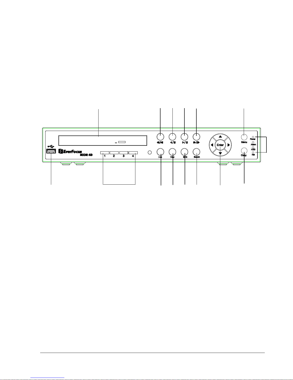
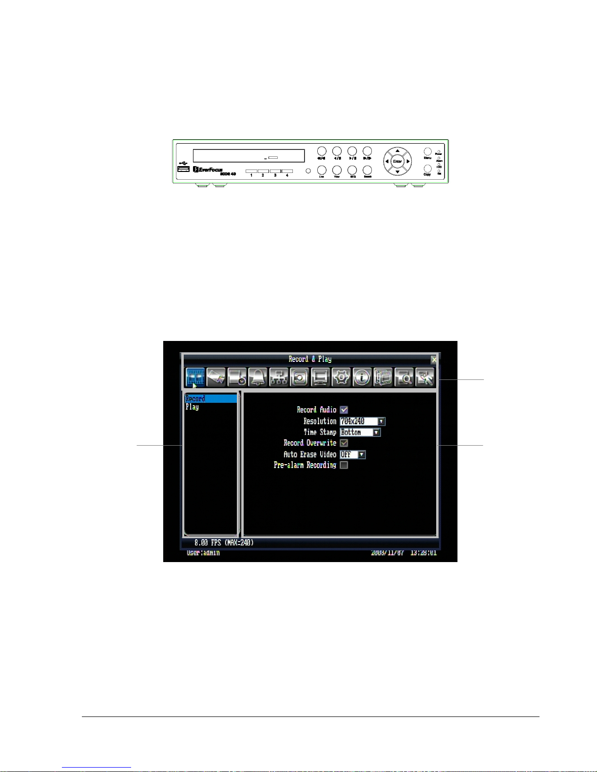
1.4 Front Panel
Your primary interaction with your new DVR will be through the Front Panel buttons and their
corresponding buttons on the included Remote Control. Take a moment to learn where the keys are as the
remainder of the manual will refer to them often.
1. USB 2.0 (front)
For connecting USB mouse or USB flash memory.
2. DVD+RW Burner
DVD+RW burner (D models only)
3. Channel Key (1~4)/(1~8)
Press channel key (CH1~CH4)/ (CH1~CH8) to display that channel in full screen view.
4. Live
Press this key to show live view. Press to exit from playback mode.
5. View
Press this key to switch between 4-screen, 9-screen, Picture In Picture, and Full-screen displays in
live and playback mode.
Note1: PIP display is not available inplayback mode.
Note2: 9-screen display available in 8 Channel model only
1
2
8910
11
14
15
131276543

6
6. SEQ
Press this key to enter the auto sequential switching mode.The sequence dwell time can be set in
“Display Setting” tab of the Menu. For more detail about SEQ, please see “5.8.2Display SettingMain M/T SEQ”.
7. Search
Press this key to enterSearch Menu. For more detail about Search function, please see “4.8
Search ”.
8. Fast reverse playback or step reverse playback depending on playback mode
9. Reverse playback or pause
10. Forward playback or pause
11. Fast Forward playback or step forward playback depending on playback mode
12. Enter and Arrow buttons
If you do not use a mouse, you can use these keys to change the Menu settings.
13. Copy
Press this key to enterCopy Menu. For more detail about Copy function, please see “4.7Copy”.
14. Menu
Press this key to enter/exitMAIN SETUP MENU.
15. System LEDs
LED displays for Power, Alarm, HDD and Net active.
7
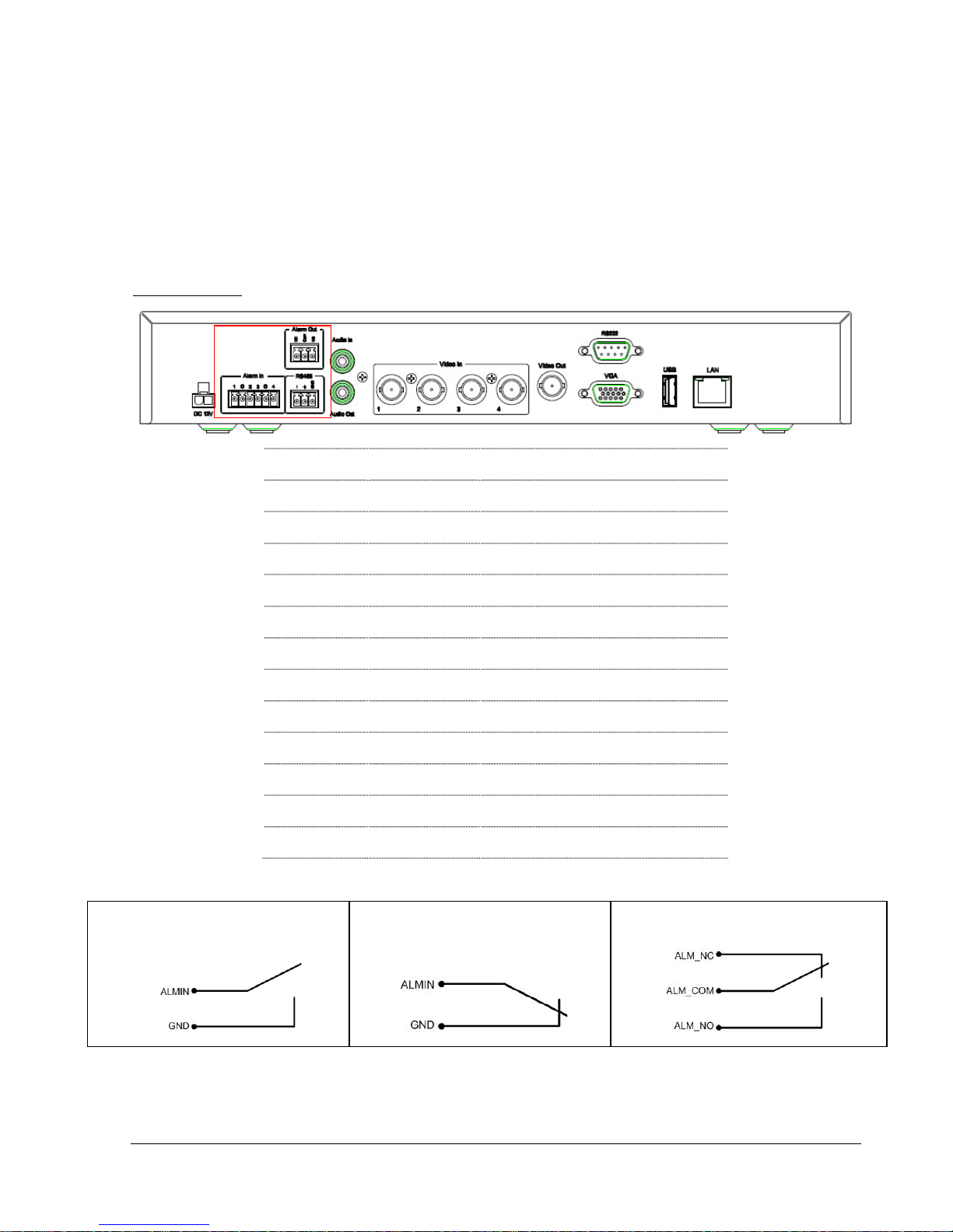
1.5 Back Panel
During initial setup you will be connecting your DVR to multiple input and output devices. This is done
through the back panel.
1. Power
Plug the DC 12V power source into the power socket.
2.Alarm In
Connect up to 4 / 8 alarm inputs, selectable between dry contact or TTL/CMOS signal polarity.
3. RS485
Terminal Connector for RS485 control.
4.Alarm Out
N.C or N.O type alarm signal out.
5. Audio Output
Connect a speaker or other audio listening devices to the audio outputconnection on the back of the digital
video recorder.
6. Audio Input
Connect a microphone orcamera audio output to the audio inputconnection.
4
6
8
10
12119
75321

8
7. Video In
Connect camera’s video output or other composite video source to the video input connection.
8. Video Out
Connect a CCTV monitor to the video output connection.
9. VGA
Connect a VGA monitor to the VGA output connection.
10. RS232
For DVR serial command control
11. USB 2.0 (back)
USB port allows you to archive video files to USBflash memorydevice or to connect the mouse.
12. LAN
RJ-45 network connection

9
2 Installation
2.1 Video Connections
Camera and CCTV monitor must use 75 Ohm video cable (e.g. RG-59, RG-6, RG-11) with BNC
connectors.
Due to inappropriate absorbability, 50 Ohm coax cable (e.g. RG-58), antenna cable and other types of
coaxial cable are notcompatible.
All connected video sources must provide a 1 Vpp NTSC or PAL standard video signal.
When converting transmission lines (twisted pair, fibre optics, radio) to the video inputs, be sure to verify
accurate receiver calibration.
ATTENTION: In order for the system to auto-detect the appropriate video format (NTSC or PAL), make
sure that there is a video signal on video input 1 upon power-up.
2.2 Audio Connection Installation
The ECOR DVR provides1 audio input and 1 audio output.
The input is designed for max. 500 mV to 10 KOhm line audio signals.
ATTENTION: The direct connection of a non-amplified microphone is not supported (a microphone
amplifier is required).
The installation must be done with audio coax cable and RCA plugs.
The output provides a max. 500 mV to 10 KOhm line audio signal and may be connected to a monitor‘s
audio input. The direct connection of passive speakers is not supported.
AUDIO RECORDING FUNCTIONALITY:
Audio recording is activated / deactivated in the RECORD menu.
Audio channel is always recorded together with video and is independent of the image recording rate.
There is no specific camera allocation.
Chapter
2
10
2.3 Alarm Input / Output Installation
ECOR DVR provides 4 / 8 alarm inputs.
Inputs have to be switched through dry contacts. The output relays provide a dry N.O./ N.C. contact..
All settings are programmed in theALARM menu.
Pin assignment:
Group
PIN label
Description
Alarm in
1
Alarm input 1
G
Common ground for alarm inputs
2
Alarm input 2
3
Alarm input 3
G
Common ground for alarm inputs
4
Alarm input 4
Alarm out
NC
Output relay, N.C. contact
COM
Output relay, common PIN
NO
Output relay, N.O. contact
RS485
-
RS485- (A)
+
RS485+ (B)
GND
RS485 GND
Default output relay state:
NO contact alarm input:
NC contact alarm input:

11
2.4 Network Connection
ECOR DVR provides fast MPEG-4 format image transmission and network remote configuration.
ATTENTION: A monitor is required for initial network configuration. For more information about
network setup, please refer to Chapter 7.
Physically, two basic types of connection are possible:
2.4.1 Direct PC Connection through Crossover Network Cable
Figure 2.1
The point-to-point connection of DVR and PC requires a crossover (crossed) network cable. This type of
connection is ONLY used for direct connection to a single PC.
Make sure that the PC is equipped with a10/100/1000 Mb compatible network connection.
2.4.2 Network Connection through Patch Cable
Figure 2.2
The connection to an existing network requires a normal patch cable (straight-through). The illustration
shows the connection to a network switch, router, or modem.
12
2.4.3 Network System Requirements
Connection type: 100Base-T
Min recommended network bandwidth: 256 K
Max. required network bandwidth:3 M
Protocol types used: TCP, UDP, SMTP, HTTP, NTP
Required ports: 80, 1600; for port information, please refer to “5.6, Network Setting”.
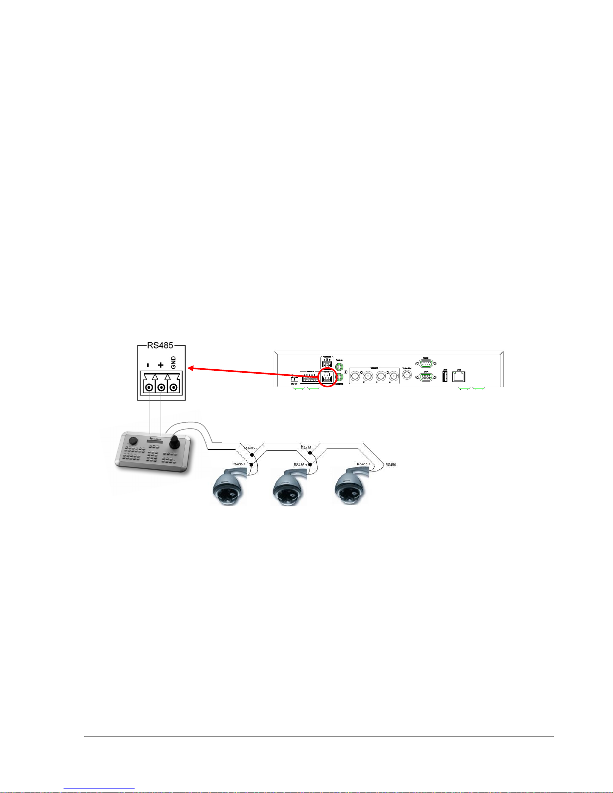
2.5 Speed Dome Installation
Speed dome or pan/tilt/zoom control is available through web browser if the DVR is connected to a
network. Local control is provided by the optional EKB 500 keyboard.
Supported protocols: EverFocus, Pelco-D, Pelco-P,Transparent, Samsung.
Figure 2.3
Sample installation with 3 EPTZ1000 speed domes and EKB500
Required DVR configuration: RS-485 receiver address in CAMERA menu; RS-485 parameters and
protocol in I/O CONTROL menu
ATTENTION: Some Pelco-D / -P protocol domes and receivers may require an address offset of -1. In
other words, the address in the DVR’s Camera Menu must be 1 below the address set in the actual dome /
receiver. (example: ID in Device = 3, ID in DVR = 2)
Termination Resistor ON

13
2.6 Final Install Process
Once you have completed the basic wiring connections, you are ready to turn on the DVR. Simply plug in
the power source. The POWER LED will light up if power is normal. Once the system has finished loading,
you can begin to set up the menu options for the DVR.
14
3 Mouse and Front Panel Operation
ECOR series DVR supports multiple sources to control the DVR. It can be controlled with a mouse, the
front panel, an EKB500, the handheld remote control, or serial command from RS232 port.
This chapter will cover the basic operationusingmouse and front panel.
3.1 General USB Mouse Operation
3.1.1 OSD Root Menu
1. Right-click the mouse to obtain DVR control bar (see Figure 3.1). When you move the mouse over each
icon, the appropriate title will be displayedon top of the control bar.
Figure 3.1
2. Click on any icon to perform that action. These actions are covered in detail in Chapter 4.
3. Click the “x” sign in the top-right corner to close the DVR control bar.
Chapter
3
15
3.1.2 Operation in Configuration Menu
The Main menu (shown in Figure 3.2) is divided into 3 main sections.
Figure 3.2 (OSD Menu)
○
1
In section 1, there are twelve setup options available.Move the mouse over an icon to select it.
○
2
In section 2, the mainoptions for the selectedicon will be displayed.Clickon a word to select it.
○
3
In section 3, all thedetails for the selectedoption will be available. Click on an option to make changes.
3.1.3 Component Options
The following are examples of different fields available in the Configuration menu.
Textbox: Click on the box and an on-screen keyboard will appear below it.
(For more details abouton-screen keyboard, please see“*Note abouton-screen keyboard”).
Dropdown box: Click on the down arrow to see all selections, then
directly click on an option toselect it.
○
1
○
3
○
2

16
Check box: Click on the box to check or uncheck it. Checked will enable the function,
unchecked will disable the function.
Button: Click the button to execute the function.
Selection box: Click Up/Down arrow toincrease or decrease the value.
Bar: Click and hold on the bar to adjust the cursorLeft orRight.
* Note about on-screen keyboard:
Click on a button to input that character.
The buttons on the right and bottom have the following functions:
<- BS
Delete the previous letter
Delete
Delete the next letter
Clear
Clear box
Enter
Confirm the selection
Caps
Switch to capital letters
Space
Enter a space
<-
Move to left
->
Move to right
Cancel
Cancel and exit from thekeyboard
17
3.2 General Front Panel Operation
3.2.1 Front Panel Key Review
The basic principle of front panel operation is to use navigation keys (up, down, left and right) to navigate
among the menu items. Use“Enter” key to confirm a selection or enter the next level menu. Press“Menu”
key to enter the Main Menu or exit from the current level of the menu.
3.2.2 Operation in Configuration Menu
Press “Menu” button to enter the Main Menu.
NOTE: If password is active, you will need to log in first. Refer to “4.2 Login” for information on logging in.
The menu (shown in Figure 3.3) is divided into 3 main sections.
Figure 3.3 (OSD Menu)
○
1
In section 1, there are twelve setup options available.Use the arrow keys tohighlight an icon and press
“Enter” to select it.
○
2
In section 2, the mainoptions for the selected icon will be displayed.Use the arrow keys to highlight an
option and press “Enter” to select it.
○
1
○
3
○
2
18
○
3
In section 3, all thedetails for the selected option will be available here. Use the arrow keys to move
between items and press “Enter” to make changes.
Note: press “Menu”button to go back to the previous menu section.
3.2.3 Component Options
Textbox: Press Enter key and an on-screen keyboard willappear below.
(For more details abouton-screen keyboard,please see *Note abouton-screen keyboard).
Dropdown box: Press “Enter” key to show the available options. Use the
Up/Down arrow keys tohighlight the desired option and press “Enter” again to select it.
Check box: Press “Enter” key to enable or disable the setting.
Button: Press “Enter” key to execute the function.
Selection box: Press “Enter” key to select the field, then use the Up/Down arrow keys to
scroll through the desired options.Press “Enter” again to choose it.
Bar: Press “Enter” key to activate the slider, then use the Left/Right arrow keys
to adjust the setting. Press “Enter” again to finalize the changes.
* Note about on-screen keyboard:
Use the arrow keys to highlight a button and press “Enter” to input that character.
The buttons on the right and bottom have the following functions:
<- BS
Delete the previous letter
Delete
Delete the next letter
Clear
Clear box
Enter
Confirm the selection
Caps
Switch to capital letters
Space
Enter a space
<-
Move to left
->
Move to right
Cancel
Cancel and exit from the keyboard
19
4 General DVR Operations
This chapter introduces the operations on major functions including playback, layout change, sequence,
triplex operations, archive, and search.
4.1 Record
By default, the ECOR series DVR will always be in record mode. When the DVR is turned on, it will start to
record.
The exceptions are:
1. ECOR will not recordany disabled cameras (Refer to section 5.3.1 for more detail)
2. If a schedule is active,ECOR will follow the recordsettings of the schedule.
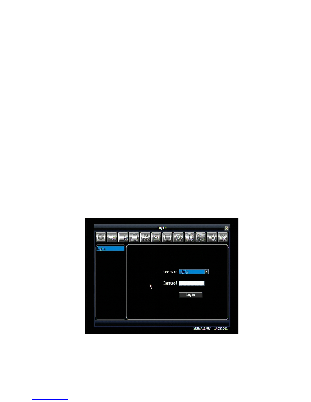
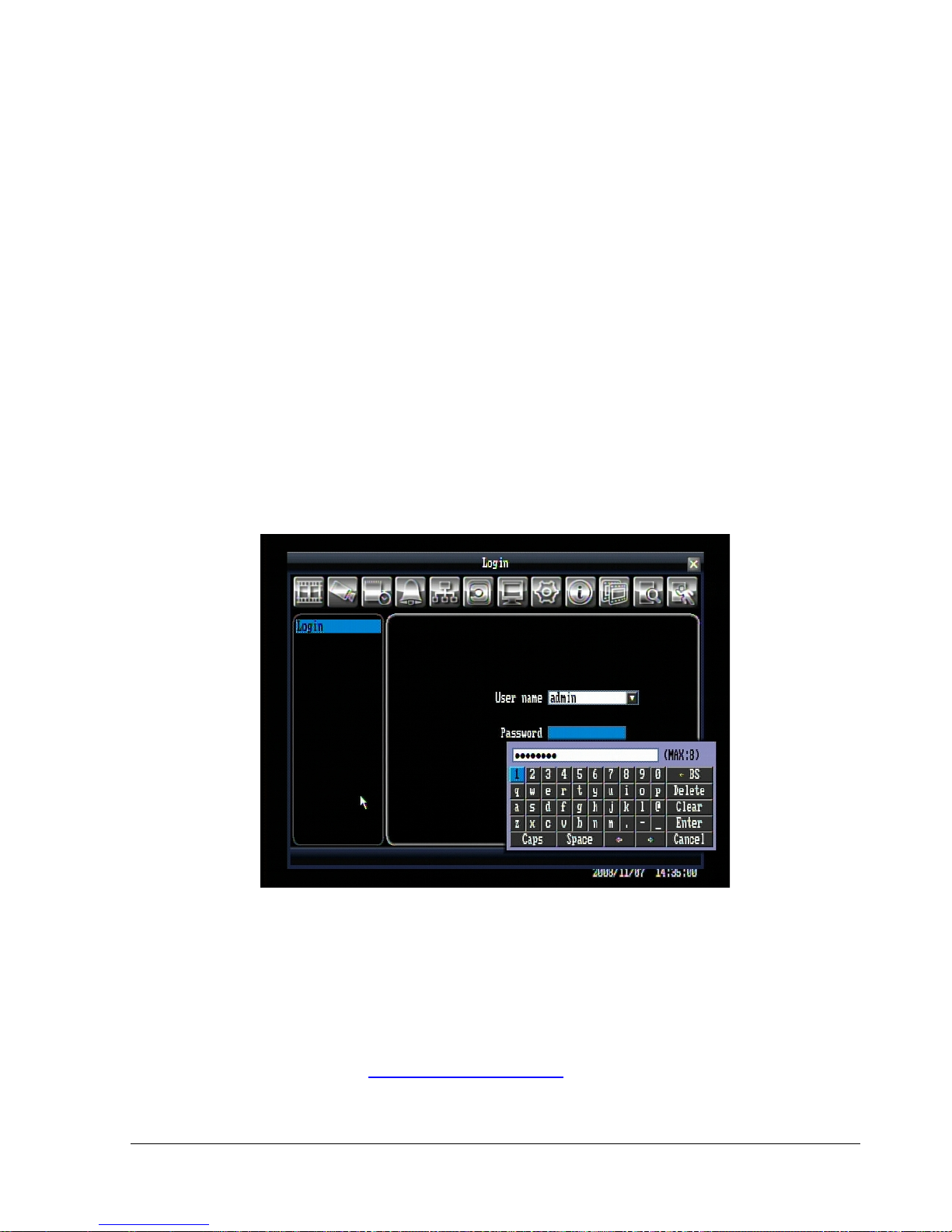
4.2 Login
In order to access ECOR options, users will be asked to log in for authority identification. To log in, follow
these steps.
1. Click on the Menu icon or press “Menu” button to bring up the following screen:
Figure 4.1 (Login page)
Chapter
4
20
2. Input the desired user name and password. The defaultsare:
User name: admin
Password: 11111111
+ To select a user name: click the drop down button to show the list of the users, then click the desired
user from the list.
(Using front panel: press “Enter” key to show the drop-down list. Use “Up” and “Down” key to select the
desired name, and press “Enter” key to confirm the selection.)
+ To input the password by mouse: click the password field to bring up the on-screen keyboard (see Figure
4.2). Click on each button to input the desired characters for the password. When finished, click “Enter” on
the on-screen keyboard to confirm the password.
(Using front panel: press“Enter” key toshow the on-screen keyboard. Use the arrow keys to highlight each
character and press “Enter” key on front panel to input the selected characters. When finished, highlight
“Enter” on the on-screen keyboardand press “Enter” key on front panelto confirm the password input.
+ Click (or press “Enter” key) on “Login” buttonto log in to the system.
Figure 4.2 (on-screen keyboard)
3. If an invalid user name or password is used 5 times, the DVR will give an error message and
automatically lockdown. No access will be granted for 10 minutes without the backdoor password. To
obtain the backdoor password, you will need to contact EverFocus Technical Support and give the
provided access code.
EverFocus Support by phone: 1-888-884-9154 (toll-free)
EverFocus Support email:techsupport@everfocus.com
21
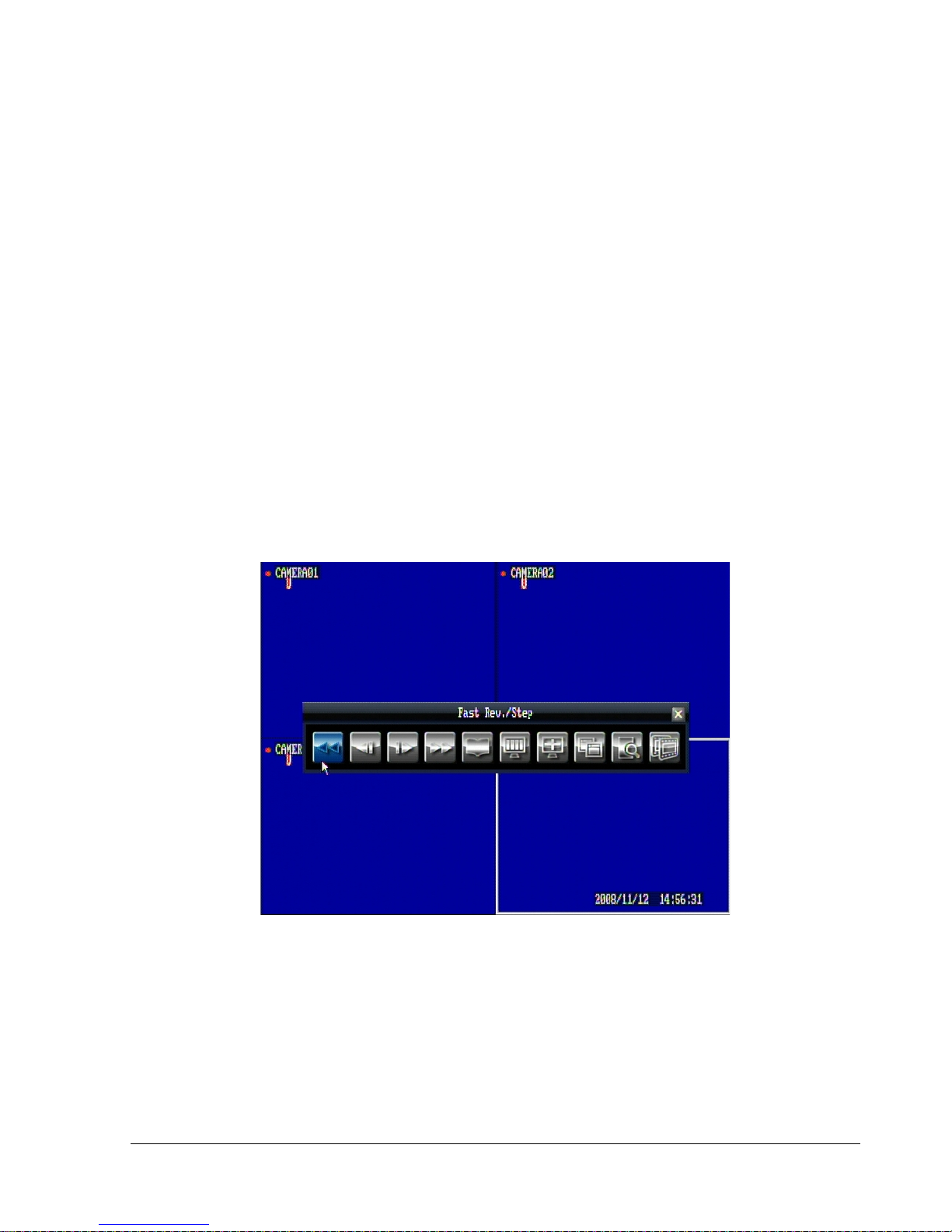
4.3 Playback Operation
4.3.1 Playback
Mouse: Right-clickwhile viewing cameras tobring up menu bar andclick to start playback.
Front panel: Press button while viewing cameras to directly start playback.
4.3.2 Reverse playback
Mouse: Right-click while viewing cameras to bring up menu bar and click to start rewind.
Front panel: Press button while viewing cameras to directly start rewind.
4.3.3 Pause
Mouse: While in playback mode, right-click to bring up menu bar and click either or to pause
the video.
Front panel: While in playback mode, press either or keys to pause the video.
4.3.4 Fast forward
Mouse: While in playback mode, right-click to bring up menu bar and click to start fast forward. Click
the button again toincrease playback speed to higher level(2x, 4x, 8x, 16x, 32x, or max).
Front panel: While in playback mode, press key to start fast forward. Press the key again to increase
speed to higher level (2x, 4x, 8x, 16x, 32x, or max).
22
4.3.5 Fast backward
Mouse: While in playback mode, right-clickto bring up menu bar and click to start fast rewind. Click
the button again to increase speed to higher level (2x, 4x, 8x, 16x, 32x, or max).
Front panel: While in playback mode, press key to start fast rewind. Press the button again to
increase speed to higher level(2x, 4x, 8x, 16x, 32x, or max).
4.3.6 Step forward
Mouse: While in pause mode, right-click tobring up menu bar and click to step forwardonce.
Front panel: While in pause mode, press key to step forwardonce.
4.3.7 Step backward
Mouse: While in pause mode, right-clickto bring upmenu barand click to step backward once.
Front panel: While in pause mode, press key to step backward once.
4.3.8 Stop playback
Mouse: While in playback or pause mode, right-click to bring up menu bar and click to go back to
live mode.
Front panel: While in playback or pause mode, press keyto go back to live mode.
4.4 Start Sequence
In sequencing mode, DVR will showeach channel in full screenbased on the configuration. For more detail
about sequence setting, please refer to “5.8.2 Main M/T SEQ”.
Mouse: Right-clickto bring up menu bar and click to start sequence
Front panel: Press key to start sequence.
23
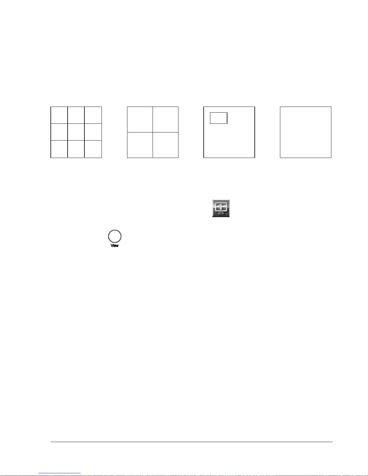
4.5 Layout Change
4.5.1 Layout Change
The 4 CH ECOR DVR has a total of three display modes available, and the 8 CH ECOR has four. The
different available layouts are shown below:
(9 screens) (4 screens) (PIP) (Full)
To change layout, follow the steps below:
By mouse: Right-click to bring up the menu bar and click to switch between 9, 4, PIP and full
displays.
By front panel: Press key to switch between 9, 4, PIP and full displays.
Notes ○19 screen display is only available for 8 CH model
○
2
PIP display is not available in Playback mode
4.5.2 Bring to Full Screen Mode
By mouse: Left-click on the selected channel toput that camerain full screen mode.
By front panel: Press any channel key to bring that channel to full screen mode.
 Loading...