

EverFocus ECOR 264x1-16, ECOR 264x1-9, ECOR 264x1-4 Instruction Manual
Instruction Manual
EECCO
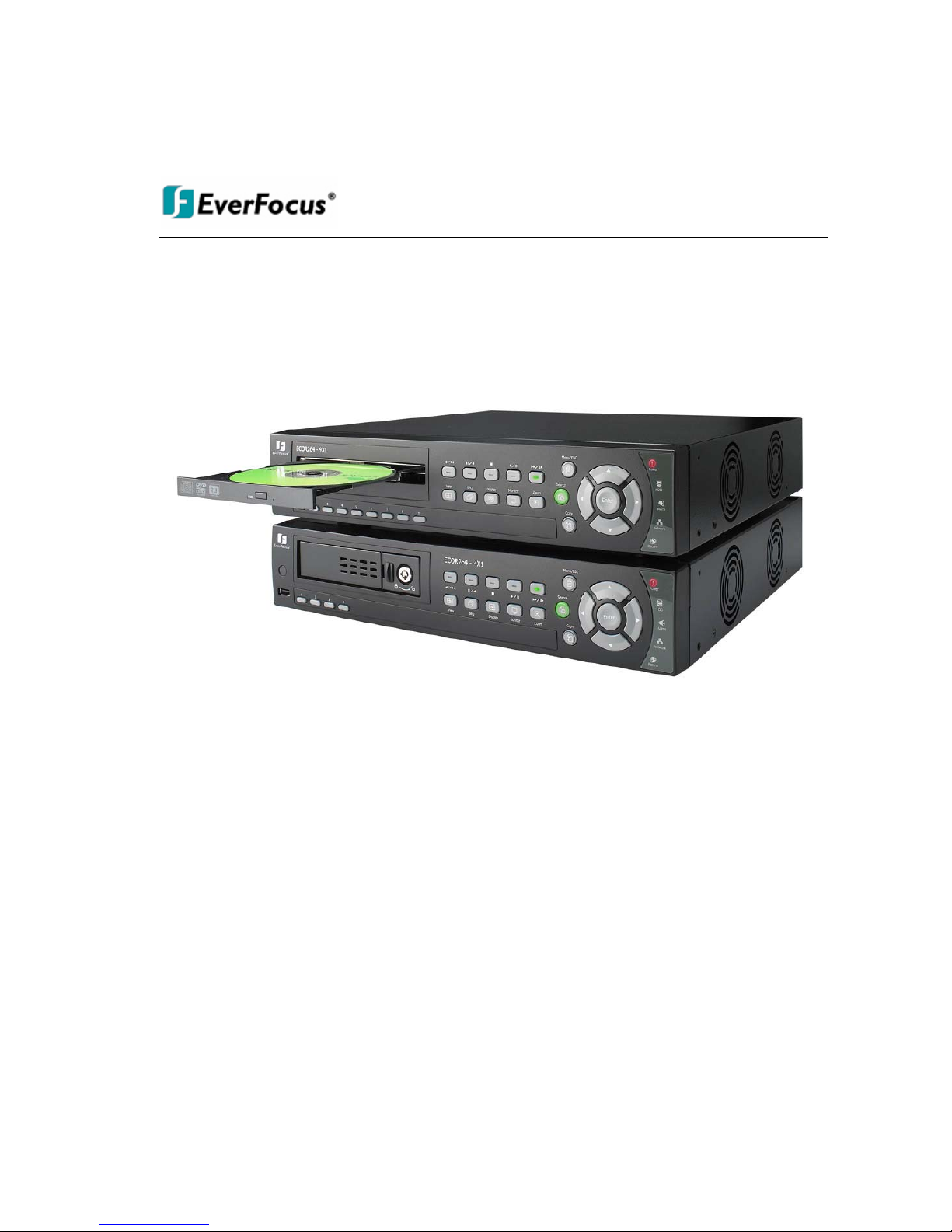
ORR 226644xx11 DDiiggiittaallrreekkoorrddeerr
EECCOORR 226644xx11--1166
EECCOORR 226644xx11--99
EECCOORR 226644xx11--4
4
2010 EverFocus Electronics Corp

ii
Safety Precautions
Refer all work related to the installation of this product to qualified service personnel or system
installers.
Do not block the ventilation opening or slots on the cover.
Do not drop metallic parts through slots. This could permanently damage the appliance. Turn the
power off immediately and contact qualified service personnel for service.
Do not attempt to disassemble the appliance. To prevent electric shock, do not remove screws or
covers. There are no user-serviceable parts inside. Contact qualified service personnel for
maintenance. Handle the appliance with care. Do not strike or shake, as this may damage the
appliance.
Do not expose the appliance to water or moisture, not try to operate it in wet areas. Do take immediate
action if the appliance becomes wet. Turn the power off and refer servicing to qualified service
personnel. Moisture may damage the appliance and also cause electric shock.
Do not use strong or abrasive detergents when cleaning the appliance body. Use a dry cloth to clean
the appliance when it is dirty. When the dirt is hard to remove, use a mild detergent and wipe gently.
Do not overload outlets and extension cords as this may result in a risk of fire or electric shock.
Do not operate the appliance beyond its specified temperature, humidity or power source ratings. Do
not use the appliance in an extreme environment where high temperature or high humidity exists. Use
the appliance at temperature within indoor type DVR for 0°C~40°C (32°F~104°F) and at relative
humidity between 20%~80%. The input power source for this device is 12 VDC with external power
supply 100~240VAC.
All rights reserved. No part of the contents of this man ual may be reproduced or transmitted in any form or by
any means without written permission of the Ev erfocus El ectronics Corporation.
Release Date: Jan. 2010
QuickTime is a registered trademark of the Apple Computer, Inc.
Windows is a registered trademark of the Microsoft Corporation.
Linksys is a registered trademark of the Linksys Corporation.
D-Link is a registered trademark of the D-Link Corporation.
DynDNS is a registered trademark of the DynDNS.org Corporation.
Other product and company names mentioned herein may be the trademarks of their respective owne rs.
iii
This Product is RoHS compliant.
ATTENTION! This is a class A product which may cause radio interference in a domestic environment; in
this case, the user ma
y
be urged to take adequate measures.
Federal Communication Commission Interference Statement
This equipment has been tested and found to comply with the limits for a Class B digital device, pursuant to
Part 15 of the FCC Rules. These limits are designed to provide reasonable protection against harmful
interference in a residential installation. This equipment generates, uses and can radiate radio frequency
energy and, if not installed and used in accordance with the instructions, may cause harmful interference to
radio communications. However, there is no guarantee that interference will not occur in a particular
installation. If this equipment does cause harmful interference to radio or television reception, which can be
determined by turning the equipment off and on, the user is encouraged to try to correct the interference by
one of the following measures :
•Reorient or relocate the receiving antenna.
•Increase the separation between the equipment and receiver.
•Connect the equipment into an outlet on a circuit different from that to which the receiver is connected.
•Consult the dealer or an experienced radio/TV technician for help.
FCC Caution: Any changes or modifications not expressly approved by the party responsible for compliance
could void the users’ authority to operate this equipment.
WEEE
The information in this manual was current upon publication. The manufacturer reserves the right to revise and improve his
products. Therefore, all specifications are subject to change without prior notice. Manufacturer is not responsible for misprints or
typographical errors.
Please read this manual carefully before installing and using this unit. Be sure to keep it handy for later reference.
Your EverFocus product is designed and
manufactured with high quality
materials and components which can be
recycled and reused.
This symbol means that electrical and
electronic equipment, at their end-oflife, should be disposed of sepa rately
from your household waste.
Please, dispose of this equipment at
your local community waste
collection/recycling cen t re.
In the European Union ther e are
separate collection systems for used
electrical and electronic product.
Please, help us to conserve the
environment we live in!
Ihr EverFocus Produkt wurde entwickelt
und hergestellt mit qualitativ hochwertigen
Materialien und Komponenten, die recycelt
und wieder verwendet werden können.
Dieses Symbol bedeutet, dass elektrische
und elektronische Geräte am Ende ihrer
Nutzungsdauer vom Hausmüll getrennt
entsorgt werden sollen.
Bitte entsorgen Sie dieses Gerät bei Ihrer
örtlichen kommunalen Sammelstelle oder
im Recycling Centre.
Helfen Sie uns bitte, die Umwelt zu
erhalten, in der wir leben!

iv
TABLE OF CONTENTS
1 PRODUCT OVERVIEW .............................................................................................................. 1
1.1 FEATURES .......................................................................................................................... 1
1.2 PACKAGE CONTENTS ......................................................................................................... 1
1.3 SPECIFICATIONS ................................................................................................................ 2
1.4 FRONT PANEL ........ ............. ................ ................ ............. ................ ................ .............. .... 3
1.5 REAR PANEL ....................................................................................................................... 5
1.6 VIDEO INPUTS/OUTPUTS INSTALLATION ............................................................................ 6
1.7 AUDIO INSTALLATION ......................................................................................................... 7
1.8 ALARM CONTACTS INSTALLATION ................. ........................................................ ............ 8
1.8.1 Alarm Input Contacts ............................................................................................. ........................................ 8
1.8.2 Alarm Output Relay ........................................................................................ ....... ........................................ 8
1.9 RS-485 KEYBOARD / PTZ INSTALLATION ..................................................................................... 9
1.9.1 General RS-485 bus installation ................................................................................................. ..................... 9
1.9.2 RS-485 socket pin assignment ...................................................................................................................... 10
1.9.3 EKB-500 connection with network patch cable ................................................................................................ 10
1.9.4 EKB-500 connection to several DVRs ............................................................................................................ 10
1.9.5 Speed Dome Installation ................................................................................. .................... ............. ............ 11
1.10 USB-MOUSE INSTALLATION ................................. ........... ............. .............. .......... .............. .. 12
1.11 NETWORK CONNECTION ............................................................................................... 13
1.11.1 Direct PC Connection through Crossover Network Cable .............................................................................. 13
1.11.2 Network Connection through Patch Cable ................................................................................................... 14
1.12 FINAL INSTALL PROCESS ............................................. .............. ................ ................ .......... 14
2 MOUSE AND FRONT PANEL OPERATION .............................................................................. 15
2.1 GENERAL USB MOUSE OPERATION . .............. .......... .............. ............. ........... ............. ............. 15
2.1.1 How to select a channel / Enable audio .......................................................................................................... 15
2.1.2 OSD Root Menu .................................................................................................... ...................................... 15
2.1.3 Operation in the Configuration Menus ............................................................................................................ 16
2.1.4 Field Input Options ....................................................................................................................................... 16
2.2 GENERAL FRONT PANEL OPERATION ........................................................................................ 18
2.2.1 How to select a channel / Enable audio .......................................................................................................... 18
2.2.2 OSD Root Menu .................................................................................................... ...................................... 18
2.2.3 Front Panel Key Review ............................................................................................................................... 18
2.2.4 Operation in Configuration Menu ................................................................................................................... 18
2.2.5 Field Input Options ....................................................................................................................................... 19
3 GENERAL DVR OPERATIONS ................................................................................................ 21
3.1 RECORD ................... ............. ............. ........... ............. .............. .......... .............. ............. ..... 21
3.2 LOGIN ................................................................................................................................. 21

v
3.3 SELECT CAMERA OPERATION .......................................... ................................ ........................ 22
3.4 CHANGE AUDIO OUTPUT ......................................................................................................... 23
3.5 PLAYBACK ........................................................................................................................ 23
3.6 PTZ ................................................................................................................................... 25
3.6.1 PTZ control panel .................................................................................................. ...................................... 25
3.6.2 PTZ Express Control .................................................................................................................................... 26
3.7 SCREEN LAYOUT .............................................................................................................. 27
3.7.1 Bring to full screen mode .............................................................................................................................. 27
3.8 CHANNEL SWITCHING ............ ................................................................ .......................... 27
3.9 STATUS DISPLAY .............................................................................................................. 28
3.10 SEQUENCE ............................ ...................................................... .................................. 28
3.11 MONITOR SWITCHING .......................................................................................................... 29
3.12 ELECTRONIC ZOOM ....................................................................................................... 30
3.13 SEARCH ......................................................................................................................... 31
3.13.1 Time Search .................................................................................. .......................................................... 31
3.13.2 Event Search ........................................................................................ ................................................... 32
3.13.3 Smart Search ........................................................................................................................................... 33
3.13.4 Snapshot Search ...................................................................................................................................... 35
3.14 COPY ............................. ........................................ ........................................ ................ 36
3.15 LOGOUT ......................................................................................................................... 36
4 DVR CONFIGURATION ........................................................................................................... 37
4.1 CONFIGURATION MENU .......................................................................................................... 37
4.2 EXPRESS .......................................................................................................................... 37
4.3 CAMERA SETTING ....................................... .................................................. ........................ 40
4.3.1 Basic Setting ............................................................................................................................................... 40
4.3.2 Video Adjust ................................................................................................................................................ 42
4.3.3 Motion .............................................................................................. .......................................................... 43
4.3.4 Video Loss .................................................................................................................................................. 46
4.4 RECORD & PLAY SETTING ................................. ................................ ................................ ..... 47
4.4.1 Record .................................................................................................... .......................... ......................... 47
4.4.2 Built-in Calculator ........................................................................................... ................... .......................... 48
4.4.3 Play ............................................................................................................................................................ 49
4.5 ALARM & EVENT SETTING ....................................................................................................... 50
4.5.1 Alarm ............................................................................................... .......................... ................................ 50
4.5.2 Event .......................................................................................................................................................... 52
4.6 SCHEDULE SETTING .................... ................................................ .......................................... 61
4.6.1 Express Setup ............................................................................................................................................. 61
4.6.2 Holidays ..................................................................................................................... ................................ 62
4.6.3 Schedule ................................................................................................. ................................................... 63
4.6.4 Alarm Action ..................................................................................... .................... ............. ......................... 68
4.7 NETWORK SETTING ............................................................................................................... 71
4.7.1 4.6.1 LAN ................................................................................................ .......................... ......................... 71
4.7.2 EMAIL ........................................................ ................................................................................................ 73
4.7.3 DDNS ......................................................................................................................................................... 74
4.7.4 Alarm Server ............................................................................... ................................................................ 76
4.8 DISK INFORMATION ................................................................................................................ 77
4.8.1 Disk ............................................................................................................................................................ 77

vi
4.8.2 Lock ........................................................................................................ ................................................... 78
4.9 DISPLAY SETTING ....................... ............................. ................................ ............................. 79
4.9.1 Monitor OSD ............................................................................... ................................................................ 79
4.9.2 Main M/T SEQ ............................................................................................................................................. 80
4.9.3 Call M/T SEQ .............................................................................................................................. ................ 80
4.10 SYSTEM SETTING ............................................................................................................... 81
4.10.1 Date/Time ................................................................................................................................................ 81
4.10.2 Daylight Saving ........................................................................ ................................................................ 82
4.10.3 User ........................................................................................................................................................ 83
4.10.4 I/O Control ............................................................................... ................................................................ 86
4.10.5 Misc. .......................................................................... ............................................................................. 87
4.11 INFORMATION .................................... ................................................ ................................ 88
4.11.1 System .................................................................................................................................................... 88
4.11.2 Log ............................................................................ ............................................................................. 89
5 NETWORKING OVERVIEW ..................................................................................................... 91
5.1 INTRODUCTION TO TCP/IP ..................... ........... ........ ........... .......... ........ ........... ........... ........ .. 91
5.2 SUBNET MASKS .................................................................................................................... 91
5.3 GATEWAY ADDRESS .............................................................................................................. 91
5.4 VIRTUAL PORTS .................................................................................................................... 92
5.5 PRE-INSTALLATION ................................................................................................................ 92
5.6 WHAT IS YOUR NETWORK SETUP? ................................. ................ .................. ................... ..... 93
5.7 SIMPLE ONE TO ONE CONNECTION ............. ........... .......... ........ ........... ........ ........... .......... ........ 94
5.8 DIRECT HIGH SPEED MODEM CONNECTION .. ........... ............. ............. ........... ............. .............. .. 98
5.9 ROUTER OR LAN CONNECTION .......... ..................... ........................ ........................ .............. 100
6 REMOTE OPERATION FROM BROWSER ................................................................................... 103
4.11.3 Installing ActiveX controls ........................................................................................................................ 104
4.11.4 Enabling ActiveX Controls ...................................................................... ................................................. 107
6.2 REMOTE LIVE VIEW ............................................................................................................. 110
6.3 REMOTE PLAYBACK ............................................................................................................. 110
7 EVERFOCUS DDNS SETUP .................................................................................................. 112
8 TROUBLESHOOTING ........................................................................................................... 114
APPENDIX A: TIMING OF ALARM MODES .................................................................................... 115
APPENDIX B: EXPRESS SETUP RECORDING VALUE SELECTION RULES .................................. 118
APPENDIX C: REMOTE CONTROL ............................................................................................... 120
APPENDIX D: MOBILE PHONE VIEWING ...................................................................................... 121

1
1 Product Overview
This new EverFocus digital video recorder is based on H.264 compression technology, resulting in
increased recording capacity and improved network image transmission spe ed while r et aining high image
quality. Comprehensive features and extended event recording settings enable the almost universa l
application of this DVR. The ECOR264-4/ECOR264-9/ECOR264-16 DVR permits multiple control inputs .
These inputs include mouse control, front panel control, IR remote control and EverFocus keyboard
(EKB500) control. Mouse control employs a simple Graphical User Interface (GUI), offering experienced
PC users the similarity of interactive command of a computer-controlled device. With the GUI, users can
command specific actions on the ECOR264-4/ECOR264-9/ECOR264-16 DVR through graphical icons and
visual indicators. Simply point, click and drag the playback bar on the screen to playback your recordings in
any time slot. All GUI functions can be operated via the front panel buttons or mouse.
The ECOR264-4/ECOR264-9/ECOR264-16 DVR is engineered for express operations. Setup, copy,
search and playback recordings in seconds with a simple “point and click” on the command icons.
1.1 FEA TURES
H.264 Compression format
Pentaplex Operation (Simultaneous live, recording, playback, archiving and remote viewing)
User friendly GU I with graphical icons and visual indicators
Free EverFocus DDNS Service
Multiple Control Inputs: mouse/front panel/remote control/keyboard
Built-in DVR calculator for fast recording estimation
Express Setup: Menu option allows quick & easy installation
Flexible alarm managament with schedule function independent from recording schedule
Remote configuration support from built-in web interface
Audio recording capabilities (audio models only)
Supports 2 internal SATA HDD or one remo v a bl e SA T A H D D
Built-in DVD burner (optional)
1 USB 2.0 port on front panel for video archive
1 USB 1.0 port on rear panel for mouse control
Multi-language support
1.2 PA CKA GE CONTENTS
Digital Video Recorder x1
User Manual x 1
AC Adapter and Power Cord x1
Mouse x 1
19" mounting brackets x1
Chapte
r
1

2
1.3 SPECIFICA TIONS
ECOR264X1
Channels 16 9 4
Compression Format H.264
Recording Rate/Resolution IPS
480 NTSC /400 PAL (CIF) 270 NTSC /225 PAL (CIF)
120 NTSC / 100 PAL in all all
modes
240 NTSC /200 PAL (Half D1) 240 NTSC /200 PAL (Half D1)
120 NTSC /100 PAL (D1) 120 NTSC /100 PAL (D1)
Playback Rate/Resolution IPS
480 NTSC /400 PAL (CIF) 270 NTSC /225 PAL (CIF)
120 NTSC / 100 PAL in all all
modes
240 NTSC /200 PAL (Half D1) 240 NTSC /200 PAL (Half D1)
120 NTSC /100 PAL (D1) 120 NTSC /100 PAL (D1)
Dual Streaming IPS 480 NTSC / 400 PAL total at CIF resolution
Pentaplex Operation Simultaneous Live, Recording, Playback, Archive and Remote Viewing
Camera Inputs 16 BNC 9 BNC 4 BNC
Looping Camera Outputs One per camera input (BNC)
Video Outputs Main VGA/BNC; Multiplex Call BNC
Audio Input/Output (RCA) 4 Inputs / 1 Output
Recording Mode Manual, Schedule and Event
Playback Search By Date/Time and Event
Alarm In 16 9 4
Alarm Out 4 relay output 1 relay output
Video Pause Yes
Video Loss Detection Yes
Motion Detection Yes
Event Log Yes
Watch Dog Timer Yes
Internal HDD 1 hot swappable or 2 internal HDD
Built-in DVD Burner Slim Type DVD Burner(Optional)
User Interface GUI(Graphical User Interface)
OS Embedded Linux
Network/Protocol Gigabit Ethernet; TCP-IP / DHCP/ PPPoE / DDNS
Control PTZ via OSD Yes
USB 2 USB port (1 x USB2.0 on Front Panel, 1 x USB1.1 on Back Panel)
Schedule Setting Supports Express and Advanced Schedule Settings
User Access 3 Levels of User Access Supported
RS-232 1 x 9 pin Sub-D socket (service purpose only)
RS-485 1 x 2 pin screw terminal connector (remote control / PTZ)
Power Source 12VDC with external power supply 100~240 VAC
Dimensions (L x W x H) 320 x 208.9 x 54.3 mm / 12.6" x 8.2" x 2.1"
Temperature 0°C~40°C / 32°F~104°F (20~80% humidity)
Certifications CE, FCC
Supported PTZ Protocols EverFocus, Pelco D, Pelco P, Samsung Electr., Transparent

3
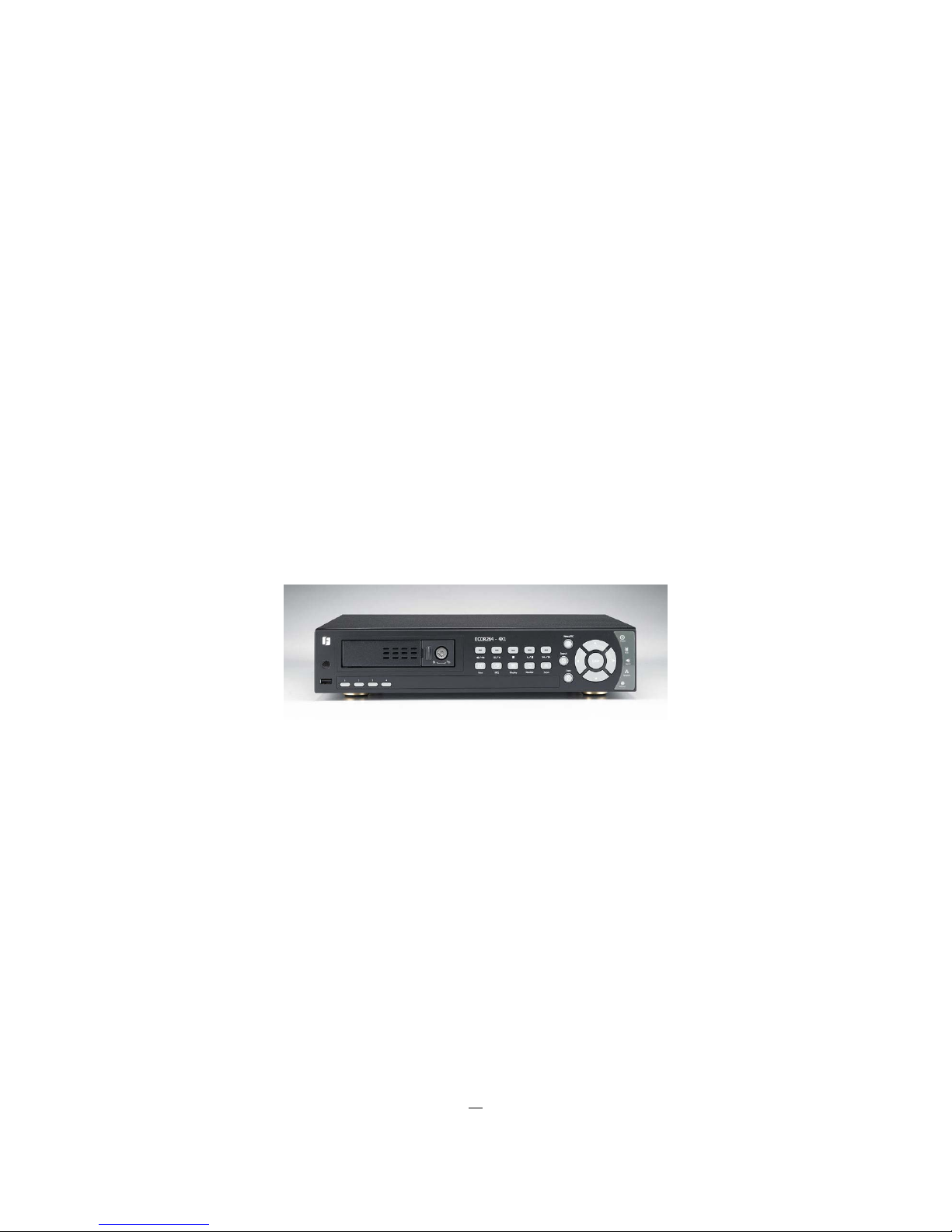
1.4 FRONT PANEL
Figure 1-1 Front Panel
1) IR Receiver: Receiver for IR remote control
2) USB 2.0 (front): For connecting USB-Flash-Drive to copy/archive video or for firmware upgrades.
3) DVD+RW: DVD+RW burner (models with DVD option only)
4) Channel keys 1~16 (1~9, 1~4): Press channel key (CH1~CH16) / (CH1~CH9) / (CH1~CH4) to display
that channel in full screen view.
5) ◄I /◄◄: Fast reverse playback or step reverse playback depending on playback mode.
6) I I / ◄: Reverse playback or pause
7)
■ Stop playback
8) ►/ I I: Forward playback or pause
9) ►►/I►: Fast forward playback or step forward playback depending on playback mode.
10) View: Press this key to switch between 4x, PiP (Picture In Picture),full screen, 9x, 10x,
13x and 16x.
Note: PIP display is not available in playback mode.
11) SEQ: Press this key to enter the auto sequential switching mode on selected monitor.
For more detail about SEQ, please see “Section 3.10 Display”.
12) Display: Press this key to switch display of channels and status bar.
12
13
14
1
2
3
9
4
6
5
7 8
10 15
11
16
17
18
19
20
21
22
23

4
13) Monitor: Short keypress: Switch between Main monitor and Call monitor.
Hold key (>1 second): Switch Main monitor display between VGA and BNC
output.
The deactivated output will show a message:
" The monitor is currently unavailable. Please hold "Monitor" key to switch."
14) Zoom: In full screen mode, 2x electronic zoom. Zoom screen can be moved through arrow
keys. Enter key changes the direction. Pressing the zoom key again switches the
electronic zoom off.
15) SEARCH: Press this key to enter Search Menu. For more detail about the Search function,
please see “Section 3.13 Search ”.
16) Menu/ESC: Press this key to enter/exit MAIN SETUP MENU.
17) Copy: Press this key to enter Copy Menu (video data export). For more detail about
Copy function, please see “Section 3.14 Copy”.
18) ENTER/ ARROW keys: Instead of or in combination with a mouse, you can use these keys to
change the Menu settings.
19) POWER LED: LED ON indicates Power on.
20) HDD LED: LED ON indicates HDD active.
21) ALARM LED: LED ON indicates Alarm active.
22) Network LED: LED ON indicates Network active.
23) Record LED: LED ON indicated Record active.
5
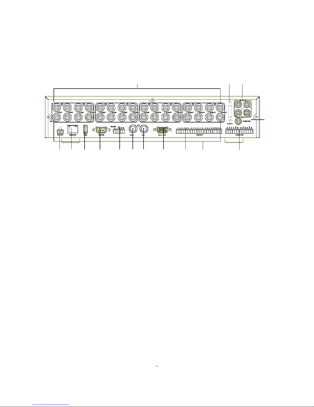
1.5 REAR PANEL
Figure 1-2 Rear Panel
1 Video In: Video input for composite signals 1 Vpp , BNC, automatic 75 Ohm terminated
2 E-SATA: Reserved for future application.
3 Audio In: 4 x Audio input, RCA socket for line audio signals 1V max., 10 KOhm impedance
.
4 POWER: DC 12V power socket for external power supply 100 ~ 240 VAC.
5 ETHERNET: RJ-45 network connection 10/100Mb/s Ethernet. There are two LEDs on the LAN jack;
Green LED means network is connected, amber LED flickers in case of traffic.
6 USB 1.0: USB port for USB mouse.
7 RS232 socket: 9-pin D-Sub control input for RS-232 for service purpose.
8 RS485 socket: Interface for remote control via RS-485 keyboards and telemetry control of connected
PTZ devices.
9 MAIN: Composite BNC output for main monitor (Live/Playback/Setup).
10 Call: Composite BNC output for CALL monitor (Live only incl. multi-view).
11 Main VGA: Main monitor - connect a VGA monitor to the VGA output connection. VGA resolution is
1024x768 @ 60 Hz.
12 Alarm In: 4/9/16 (depending on model) alarm N.O. or N.C.inputs for dry contacts.
13 Video Out: Loop-through video outputs 1 V
pp
, BNC (1:1 connected to video inputs).
6 5
7 8
10
11 12
9
15
1
2 3
4
13
14

6
Note: Make sure that the connected monitor or other video device input is terminated
with 75 Ohm.
Connecting a BNC v ideo cable at this output switches off the in t er n a l 75 Ohm
termination!
14 Alarm Out: N.C / N.O relay output. (ECOR264-4: 1 x , ECOR264-9/16: 4x)
15 Audio Out: Audio output, RCA socket, line audio signal 1V max at 10 KOhm
.
.
1.6 VIDEO INPUTS/OUTPUTS INST ALLATION
Camera and CCTV monitor must use 75 Ohm video cable (e.g. RG-59, RG-6, RG-11) with BNC
connectors.
To avoid impedance mismatch and undesired loss/reflections, 50 Ohm coax cable (e.g. RG-58), antenna
cable and other types of coaxial cable are not compatible.
All connected video sources must provide a 1 Vpp NTSC or PAL standard video signal.
When converting transmission lines (twisted pair, fiber optics, radio) to the video inputs, be sure to verify
accurate receiver calibration and signal levels.
ATTENTION: In order for the system to auto-detect the appropriate video format (NTSC or PAL), make
sure that there is a video signal on video input 1 upon power-up.
The "Out" BNC sockets allow to loop the video input signal to additional video devices.
Note: Make sure that the connected monitor or other video device input is terminated with 75 Ohm.
Connecting a BNC video cable at this output switches off the internal 75 Ohm termination!
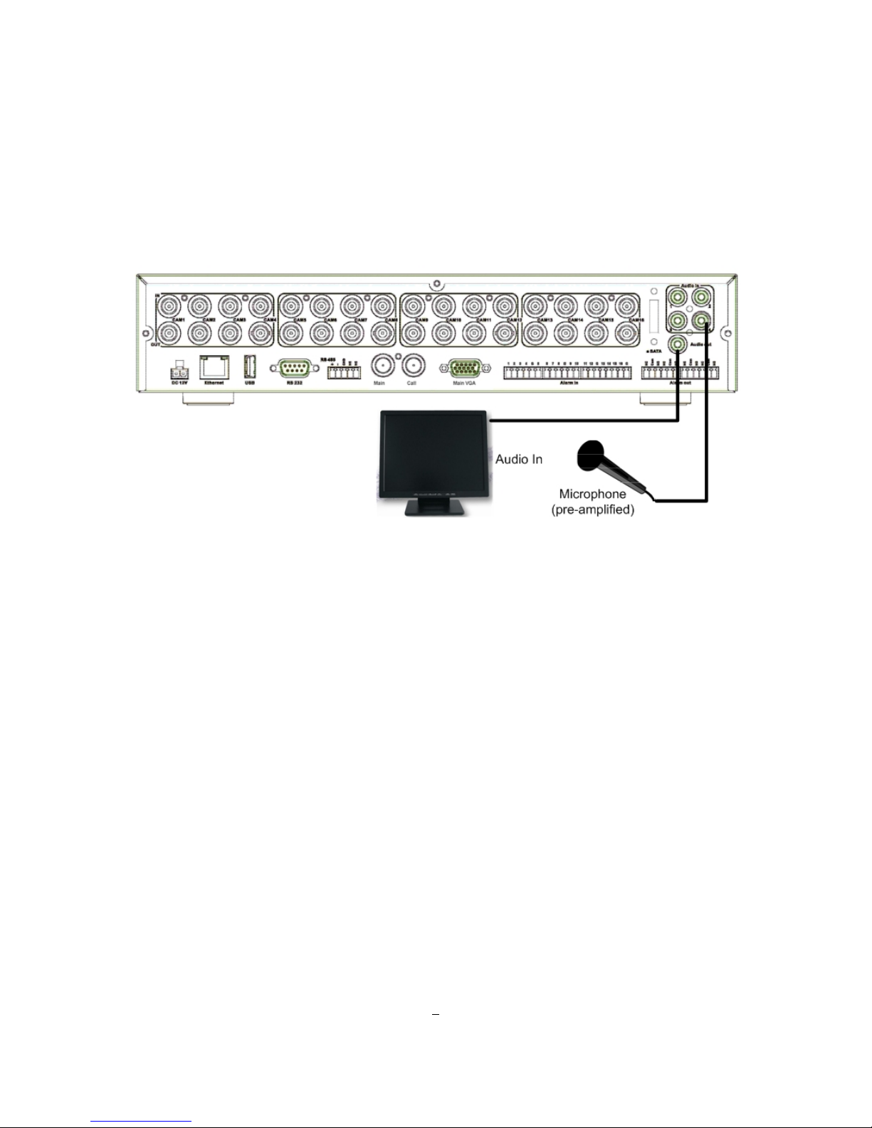
7
1.7 AUDIO INSTALLATION
This DVR provides 4 audio inputs and 1 audio output.
ATTENTION: The direct connection of a non-amplified microphone is not supported (a microphone
amplifier is required).
The installation must be done with audio coax cable and RCA plugs.
AUDIO RECORDING FUNCTIONALITY:
The audio channels 1...4 are assigned to the video input channels 1...4 for recording, playback and network
stream.
Audio recording is activated / deactivated in the Camera Menu for Camera #1~4. Please check and always
comply with local laws and regulations when using audio recording.
The audio channels are always recorded together with video and is independent of the image recording
rate.
8
1.8 ALARM CONT A CTS INSTALLA TION
The alarm inputs can be used to start recording or for recording rate adjustment. In addition, alarm
reactions such as camera display on the monitor, buzzer, e-mail and network alarm are available. The
alarm output relay can be switched if required. Alarm input response actions can be controlled according to
a flexible schedule.
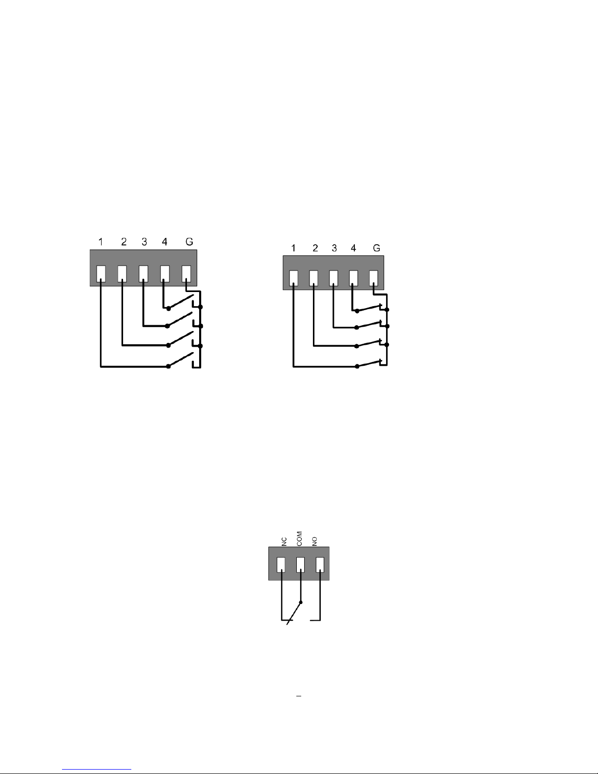
1.8.1 Alarm Input Contacts
This DVR provides one alarm input per camera. All inputs are programmable N.O. (Normal Open) or N.C.
(Normal Closed) inputs have to be switched by d ry contacts.
Alarm input with N.O. (Normal Open) contact Alarm input with N.C. (Normal Closed) contact
in idle state (contacts 9~16 similar) in idle state (contacts 9~16 similar)
All settings are programmed in the ALARM menu (Section 4.5.1).
1.8.2 Alarm Output Rela y
The relay outputs provides Normally Open and Normally Closed dry contacts.
Number of output relais:
ECOR264x1-4: 1 relay out
ECOR264x1-9: 4 relay out
ECOR264x1-16: 4 relay out
Output relay in idle state
9
1.9 RS-485 keyboard / PTZ Installation
All functions can be remote-controlled by the EKB-500 universal keyboard. Using the EEPbus protocol,
digital video recorders, keyboards and speed domes can be installed on one single RS-485 bus. One
system can comprise up to 8 keyboards.
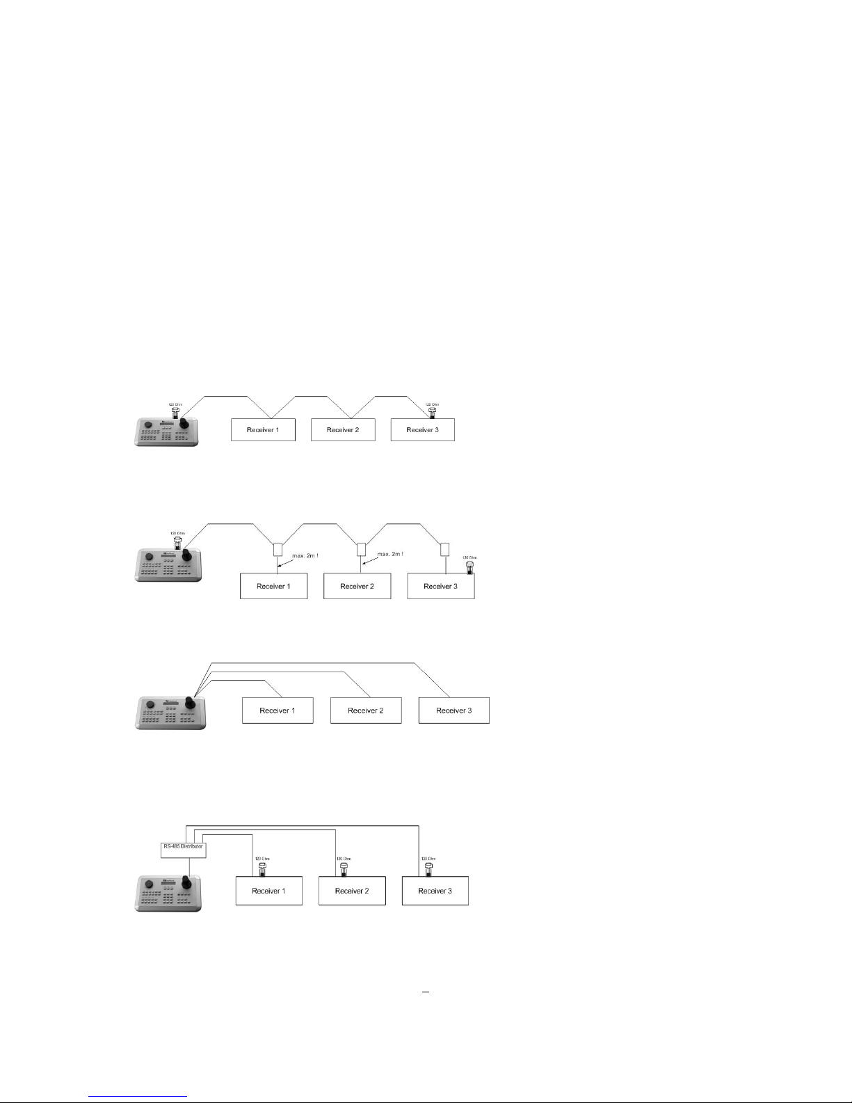
1.9.1 General RS-485 bus installation
The EKB-500 keyboard uses a RS-485 simplex wiring; the signal is transferred via a single twisted pair line.
CAT5 network cable is recommended, UTP version (unshielded) is sufficient for normal applications. A
shielded cable should be used if the installed cables are expected to be highly susceptible to interference.
The number of devices installed in one bus is limited to 32, and the maximum cable length is 3,900 feet.
Both of these can be expanded using a signal distributor (see below).
Both the first and the last device in series should be terminated with 120 Ohm resistance in order to
minimize li ne reflect ions.
RS-485 bus serial wiring
Cable length from box to device („Stubs“) has to be limited to 2m using connector boxes.
RS-485 bus serial wiring with connector boxes and connection cable
A direct RS-485 bus star wiring is not supported unless using a signal distributor (see below).
Improper RS-485 bus star wiring
A RS-485 signal distributor may be used to use a star wiring configuration.
Star wiring with RS-485 signal distributor
10
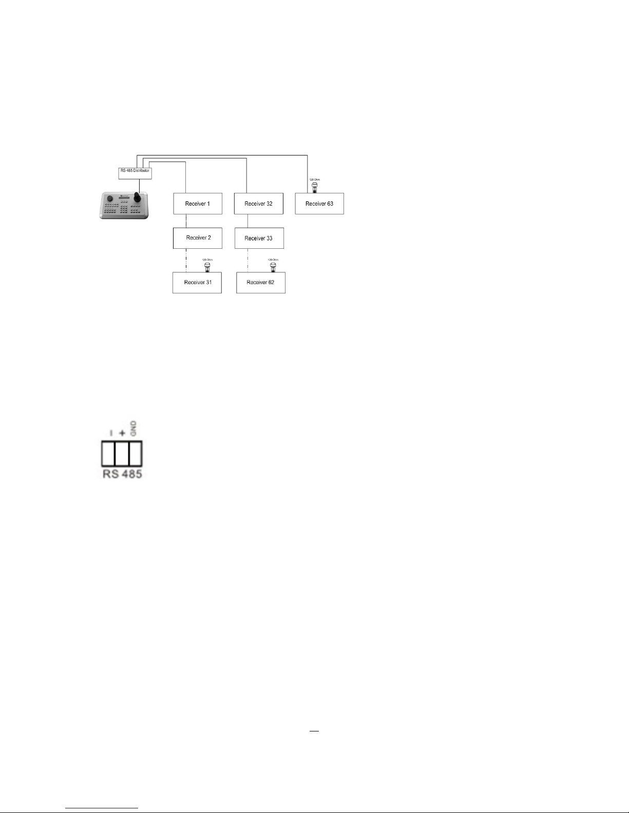
A RS-485 distributor can also be used to increase the maximum number of devices on the bus as well as
the total range. Each distributor output provides another RS-485 bus. This allows each output to extend an
additional 1200m, and it also enables the additional connection of 31 further devices to each output (the
output itself represents one device).
The maximum system expandability depends on the RS-485 address range of the installed devices.
System expansion with RS-485 signal distributor
ATTENTION: Most signal distributors are unidirectional! This means that the signal only flows from the
input towards the outputs. Therefore, e.g. the interconnection of several keyboards is not possible with
these types of signal distributor!
1.9.2 RS-485 socket pin assignment
The RS485 pin assignment is as follows:
1.9.3 EKB-500 connection with network patch cable
For a simple, short distance installation, recorder and keyboard can be connected directly using a standard
CAT5 network cable with an 8-pin connector at only one end, and at the other end the Pin 3 wire connected
to RS485 “+” (plus) and the pin 6 wire connected to RS-485 “-“ (minus).
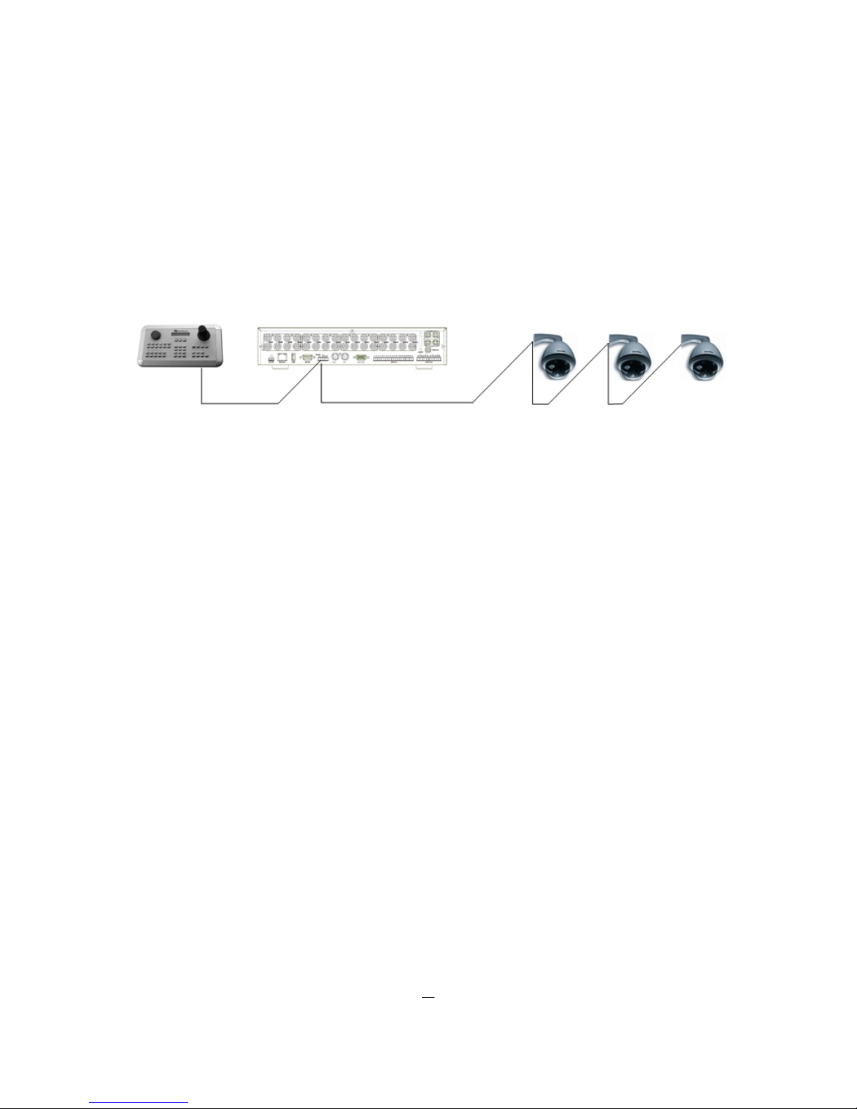
1.9.4 EKB-500 connection to several DVRs
For long distance installations connecting several DVRs, please use a signal distributor to connect
For further details on keyboard connection, please refer to the EKB-500 manual.
RS-485 port communication settings are configured in the I/O CONTROL menu (Section 5.10.4 System
Setup: I/O - control).
11
1.9.5 Speed Dome Installation
Speed dome or telemetry receiver pan/tilt/zoom control is available through web browser or the optional
PowerCon software if the DVR is connected to a network. Local telemetry control is provided by USB mouse control or by the optional EKB-500 keyboard.
Supported protocols: EverFocus, Pelco-D, Pelco-P, Samsung, Transparent
Required DVR settings: RS- 48 5 r e c e i ver address in CAMERA menu
(Section 4.3)
RS-485 parameters and protocol in the I/O CONTROL menu
(Section 4.10.4)
ATTENTION: Some Pelco-D / -P protocol domes and receivers require an address offset of -1, i.e. the
address assigned to the dome / receiver in the DVR camera menu must be 1 below the address set in the
dome / receiver itself!
12
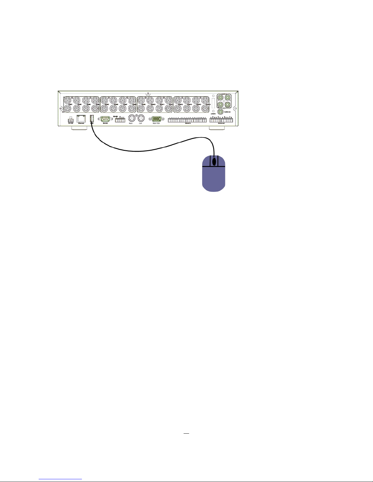
1.10 USB-Mouse installa tion
Connect the USB mouse to one of the back panel USB port. (possible also in operation). The rear USB
V1.0 port is recommended to reserve the higher speed front USB V2.0 port for video copy/export.
NOTE: Recommended mouse types are Logitech® and Microsoft® wired USB wheel-mouse. Wireless
USB mouse is not supported.

13
1.11 NETW ORK CONNECTION
This section only describes physical connection to an Ethernet network. This step must be completed
before the DVR can connect to the network. There are two basic types of connection:
1.11.1 Direct PC Connection through Crossover Network Cable
The point-to-point connection of DVR and PC requires a crossover (crossed) network cable. This type of
connection is ONLY used for direct connection to a single PC. Make sure that the PC is equipped with a
10/100/1000 Mbps compatible network connection.
Figure 1-3 Direct PC Connection
Pinout of crossover-cable
14
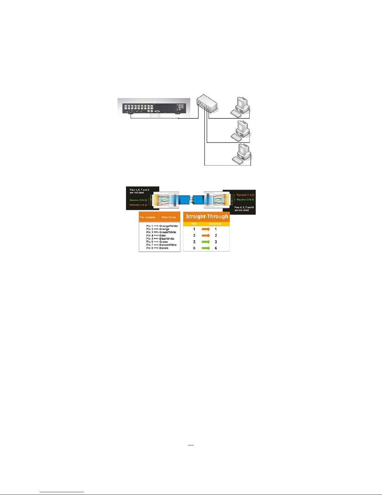
1.11.2 Network Connection through Patch Cable
The connection to an existing network requires a normal patch cable (straight-through). The illustration
shows the connection to a network swit ch or router.
Figure 1-4 Network Connection through Patch Cable
Pinout of straight patch cable
1.12 Final Install Process
Once you have completed the basic wiring connections, you are ready to turn on the DVR. Simply plug in
the power source. The POWER LED will light up if power is normal. Once the system has finished loading,
you can begin to set up the menu options for the DVR.

15
2 Mouse and Front Panel Operation
ECOR264 DVRs support multiple options to control the DVR. It can be controlled with a mouse, the front
panel, an EKB500, and the handheld remote control.
This chapter will cover the basic operation using the m ouse and the front panel buttons.
2.1 General USB Mouse Operation
2.1.1 How to select a channel / Enable audio
1. In a view consisting of more than one channel, users can select a channel by clicking once on the
desired channel screen. The selected screen will be highlighted by a white frame.
2. Double clicking on a channel screen will display full screen for this channel.
3. To enable audio out, click the audio icon (ex:
) at lower side of the screen. This system has only
one audio out. Click this button to enable or disable the audio-out mode.
2.1.2 OSD Root Menu
1. Right-click the mouse to obtain the DVR control bar (see Figure 2-1 OSD Root Menu ). When you move
the mouse over each icon, its title will be displayed at the top of the control bar.
Figure 2-1 OSD Root Menu
2. Click on any icon to perform that action. These actions are covered in detail in chapters 3 and 4.
3. Click the “X” in the top-right corner to close the DVR control bar.
Chapte
r
3
16
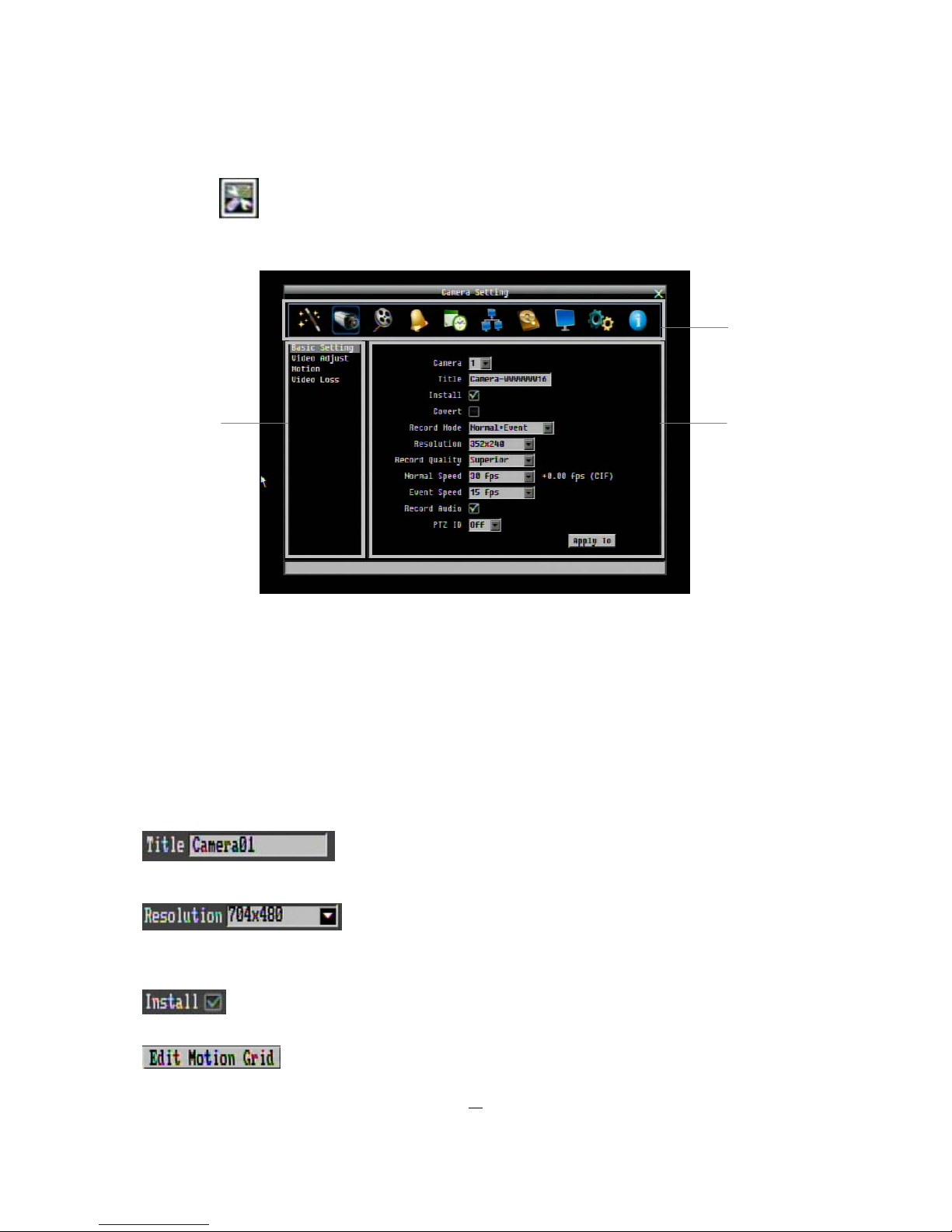
2.1.3 Operation in the Configuration Me nus
Click on the
icon to access the Configuration Menu.
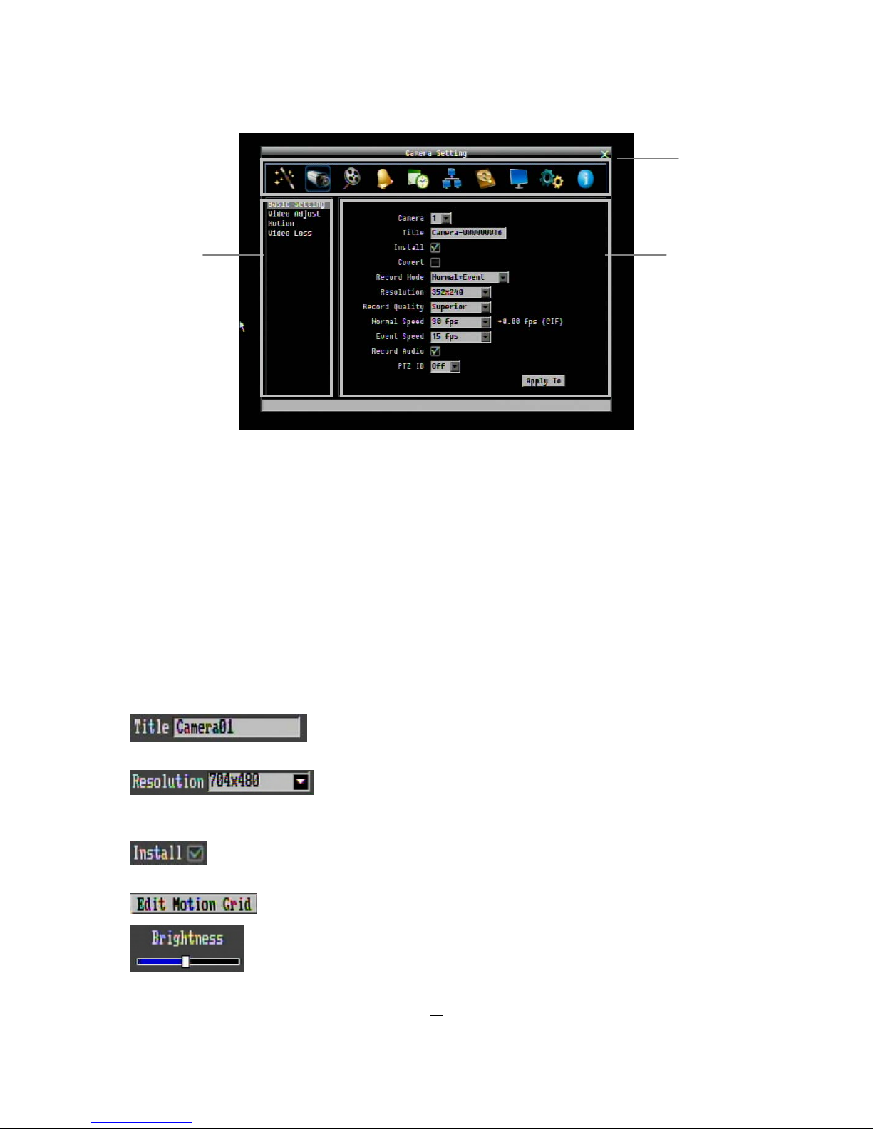
The Configuration menu screens (shown in Figure 2-2 OSD Menu) are divided into 3 main sections.
Figure 2-2 OSD Menu
1: In section 1, there are ten setup options available. Move the mouse over an icon and click to select it.
2: In section 2, the categories for the selected icon will be displayed. Click on a choice to select it.
3: In section 3, all the options for the selected choice will be available. Click on a field to make changes.
2.1.4 Field Input Options
The following are examples of different types of fields available in the Configuration menu.
Textbox:
Click on the box and an on-screen keyboard will appear*. (see
note about the on-screen keyboard below)
Dropdown box:
Click on the down arrow to see all selections, then
directly click on an option to select it.
Check box: Click on the box to enable it (checked) or disable it
(unchecked).
Button: Click the button to execute the function.
1
3
2
17
Bar: Click and hold on the bar to adjust the set point Left or Right.
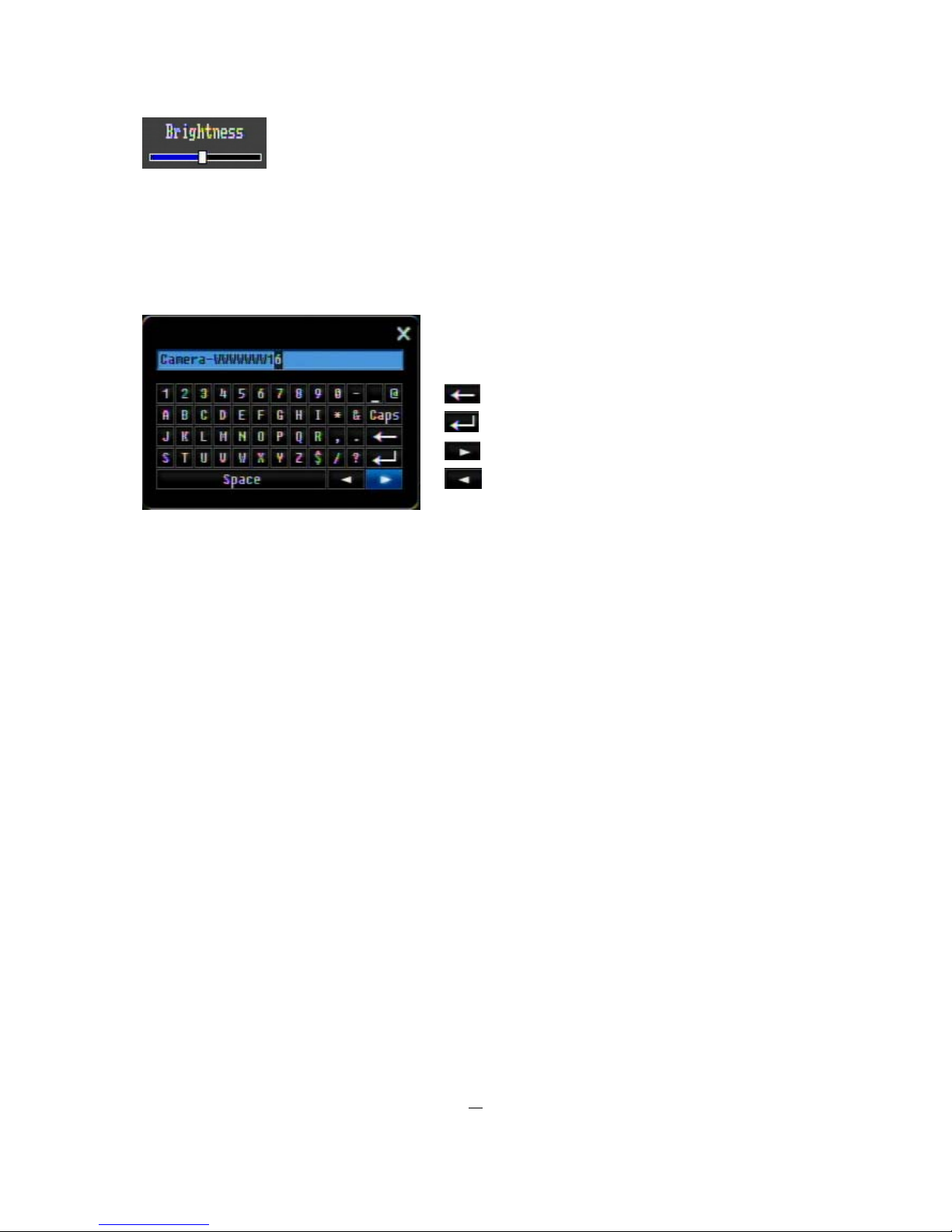
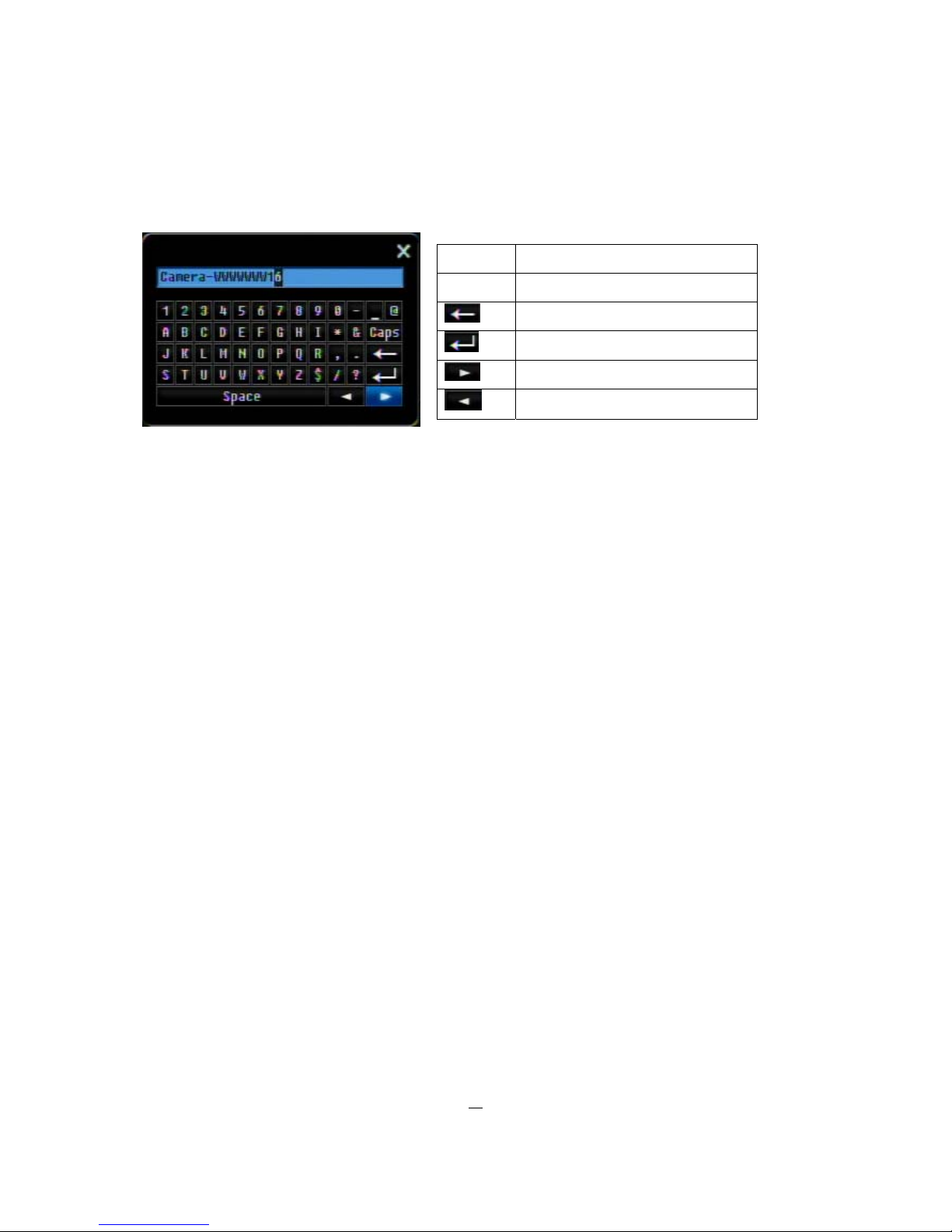
* Note about on-screen keyboard:
Click on a button to input that character.
The buttons on the right and bottom have the following functions:
.
Space Enter a space
Caps Switch to capital letters
Delete the letter
Confirm the selection
Move to right
Move to left
18
2.2 General Front Panel Operation
2.2.1 How to select a channel / Enable audio
1. In a view consisting of more than one channel, use the mouse or press arrow keys
(Up/Down/Right/Left) to scroll through each channel that is displayed. The selected channel will be
highlighted by white frame. Pressing the “right” arrow when the last camera (4, 9 o r 16) is highligh ted
will select all cameras.
2. While channel #1 is selected, press the “Enter” button to turn Audio On/ Off.
2.2.2 OSD Root Menu
1. Press “Menu” key to display the DVR control bar. Use the left/right arrows to scroll over each icon. The
title for each icon will be displayed on top of the control bar.
2. Press “Enter” key on any icon to perf or m that action. These actions are covered in detail in Chapter 3
3. Press “Menu” to close the DVR control bar.
2.2.3 Front Panel Key Review
The basic principle of front panel operation is to use arrow keys to navigate among the menu items. Use
the “Enter” key to confirm a selection or enter the next level menu. Press the “Menu” key to enter the Main
Menu or exit from the current level of the menu.
2.2.4 Operation in Configuration Me nu
Press “Menu”, use the arrow keys to highlight the “Configuration” icon, and press “Enter” with
“Configuration” icon highlighted to bring up the Configuration menu.
NOTE: If the function "User Login" is active (menu SYSTEM / US ER, chapter 4.10.3), you have to log in
first. Refer to “Section 3.2 Login” for information on logging in.
19
The menu (shown in Figure 2-3 OSD Menu ) is divided into 3 main sections.
Figure 2-3 OSD Menu
1) In section 1, there are ten setup options available. Use arrow keys to highlight an icon and press “Enter”
to select it.
2) In section 2, the main choices for the selected ic on will be displayed. Use Up/Down arrow keys to
highlight a choice and press “Enter” to select it.
3) In section 3, all the options for the selected choice will be available here. Use arrow keys to move
between items and press “Enter” to make changes.
Note: press “Menu” button to go back to the previous menu section.
2.2.5 Field Input Options
Textbox: Press Enter key and an on-screen keyboard will appear*. (see
note about on-screen keyboard below)
Dropdown box: Press “Enter” key to show the available options. Use
arrow keys to highlight the desired option and press “Enter” again
to select it.
Check box: Press “Enter” key on a setting to enable it (checked) or disable it
(unchecked).
Button: Press “Enter” key to execute the function.
Bar: Press “Enter” key to activate the slider, then use arrow keys to adjust the
setting. Press “Enter” again to finalize the changes.
1
3
2
20
* Note about on-screen keyboard:
Click on a button to input that character.
The buttons on the right and bottom have the following functions:
Space Enter a space
Caps Switch to capital letters
Delete the letter
Confirm the selection
Move to right
Move to left

21
3 General DVR Operations
This chapter introduces the operations on major functions including playback, layout change, sequence,
triplex operations, copy, and search.
3.1 Record
By default, the DVR will always be in record mode. When the DVR is turned on, it will start to record. The
exceptions are:
1. DVR will not record any cameras, which are not programmed as "Installed" (Refer to Section 4.3.1
for more details)
2. If a schedule is active, the DVR will follow the record settings of the schedule.
3.2 Login
In order to access ECOR264x1 options, users may be asked to log in for authority identification depending
on settings for USER LOGIN (menu SYSTEM / USER, chapter 4.10.3). To log in, follow these steps.
1. Right click on the screen or press the Menu Key to display the Main Menu
2. Choose or click (or press “Enter” key) on the Configuration icon to bring up the following screen
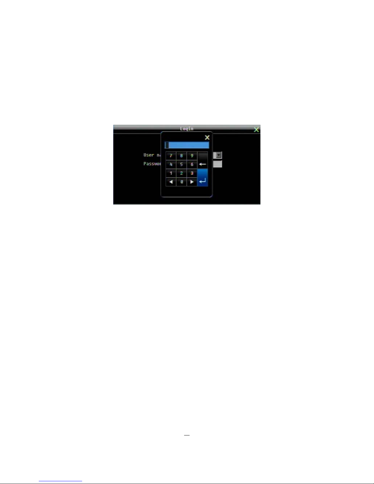
(in factory settings the Login function is disabled) :
Figure 3-1 Login page
3. Select the user name from the drop-down list and input the password. The defaults are:
User name:
admin (lower case)
Password:
11111111
Chapte
r
3
22
+ To input password by mouse: click the password field to bring up the on-screen keyboard (see Figure 3-2
On-screen Keyboard). Click on each button to input the desired characters for the password. When finished,
click “Done” on the on-screen keyboard to confirm the password.
+ To input password using front panel: press “Enter” key to show the on-screen keyboard (see Figure 3-2
On-screen Keyboard). Use the arrow buttons to highlight each character and press the “Enter” key on the
front panel to input the selected characters. When finished, highlight “Done” and press the “Enter” key on
the front panel to confirm the password.
+ Click (or press “Enter” key) on the “Login” button to log in to the system.
Figure 3-2 On-screen Keyboard
3.3 Select Camera operation
ECOR264x1 is a pentaplex DVR; users can control each camera individually by selecting that camera. For
camera selection:
Mouse: Right-click the screen, the image will show a white frame on screen if the camera has been
selected. The mouse wheel browses between selected cameos.
For selection of all cameras scroll with mouse wheel to position after last or before first camera in the multiview. All cameras will be marked with white frame.
.Front panel: Use the arrows to change the selection. Pressing the “right” arrow when the last camera (4, 9
or 16) is highlighted will select all cameras.

23
3.4 Change Audio output
Use arrow keys to select camera #1 and press “Enter” key to switch audio output on and off. An audio icon
will appear on the screen. Please make sure “Record Audio” option under Camera 1~4 Basic Settings
setup menu is ON if audio recording is required. Also, the audio source and/or audio output amplifier have
to be connected properly in order to utilize the audio functions.
Note: For playback, network stream and video export the audio streams 1~4 are assigned to the video
channels 1~4.
3.5 PLAYBACK
The playback bar is the fastest way to show video from the exact time which users want to see. The
playback bar allows a user to see both a time line and the current playback indicator. The user can then
click the time line to move the indicator to the position which they want to see. The operation is as follows:
To playback:
By mouse: Right-click to bring up the menu bar and click on
to enter Playback Menu.
By front panel : Press
key to enter Playback Menu.
The playback bar will show (see figure below):
2009/05/25 09:09:30PM 2009/05/25 09:09:40PM 2009/05/25 09:10:30PM
1. Stop key: press to stop playback
2. Slow Reverse key: press to start slow reverse playback
3. Pause key: press to pause playback
4. Slow Forward key: press to start slow forward playback
5. Fast Reverse key: press to start fast reverse playback
6. Reverse key: press to start reverse playback
7. Forward key: press to start forward playback
8. Fast Forward key: press to start fast forward playback
9. Time bar: Move the slider on the time bar to the select time to playback (The start time and end time for
time bar appears below the bar). The status of each camera is represented by different colors on the
time bar. Green means normal; orange indicates a Motion; blue indicates Video Loss, red indicates an
alarm event.
14 15 16

24
10. “+” and “-“ signs are used to adjust the time scale range for the bar. Press “+” or “-“ to select between
scale levels L1 ~ L5. When changing level, the start time and end time of the time bar will change)
L1: Entire time bar is 2 days
L2: Entire time bar is 30 hours.
L3: Entire time bar is 1 hour.
L4: Entire time bar is 10 minutes.
L5: Entire time bar is 1 minute.
11. Express copy: Press to start express copy when camera during playback (only one camera)
12. Playback speed indicator
13. Press “X” to close the playback bar.
14. Start time for bar (the left-most point of the time bar)
15. Current playback time (the time indicated by the slider)
16. End time for time bar (the right-most point of the time bar)
 Loading...