

Page 1
User Manual
ECC
E
ECC
E
O
R226644--44FF11//
O
R
O
R226644--88FF11//
O
R
ECC
E
ECC
E
O
R226644--44
O
R
O
R226644--88
O
R
D11
D
D11
D
Page 2

EVERFOCUS ELECTRO N I C S CORPORA T I O N
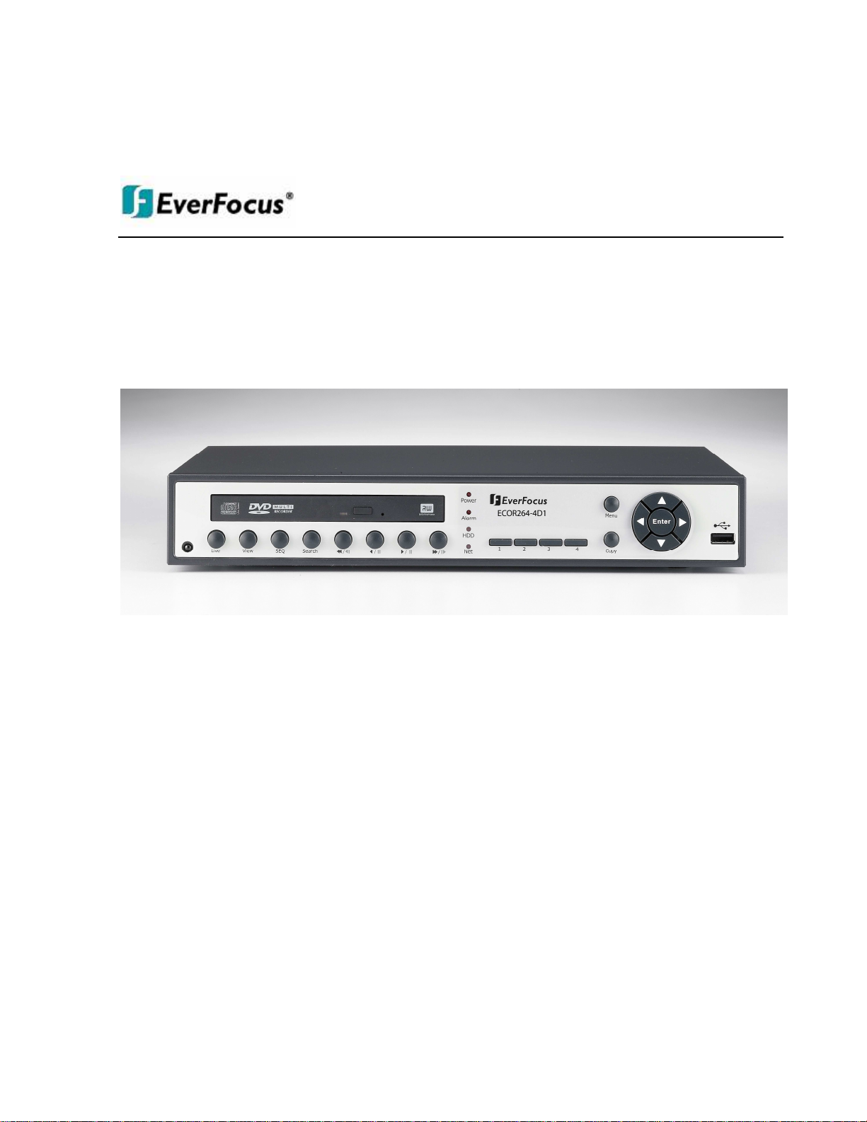
ECOR264-4F1/ ECOR264-4D1
ECOR264-8F1/ ECOR264-8D1
Instruction Manual
2009 EverFocus Electronics Corp
www.everfocus.com
All rights reserved. No part of the contents of this manual may be reproduced or transmitted in any form or by
any means without written permission of the Everfocus Electronics Corporation.
Release Date: Nov. 2009
QuickTime is a registered trademark of the Apple Computer, Inc.
Windows is a registered trademark of the Microsoft Corporation.
Linksys is a registered trademark of the Linksys Corporation.
D-Link is a registered trademark of the D-Link Corporation.
DynDNS is a registered trademark of the DynDNS.org Corporation.
Other product and company names mentioned herein may be the trademarks of their respective owners.
Page 3

Safety Precautions
Refer all work related to the installation of this product to qualified service personnel or system
installers.
Do not block the ventilation opening or slots on the cover.
Do not drop metallic parts through slots. This could permanently damage the appliance. Turn the
power off immediately and contact qualified service personnel for service.
Do not attempt to disassemble the appliance. To prevent electric shock, do not remove screws or
covers. There are no user-serviceable parts inside. Contact qualified service personnel for
maintenance. Handle the appliance with care. Do not strike or shake, as this may damage the
appliance.
Do not expose the appliance to water or moisture, not try to operate it in wet areas. Do take immediate
action if the appliance becomes wet. Turn the power off and refer servicing to qualified service
personnel. Moisture may damage the appliance and also cause electric shock.
Do not use strong or abrasive detergents when cleaning the appliance body. Use a dry cloth to clean
the appliance when it is dirty. When the dirt is hard to remove, use a mild detergent and wipe gently.
Do not overload outlets and extension cords as this may result in a risk of fire or electric shock.
Do not operate the appliance beyond its specified temperature, humidity or power source ratings. Do
not use the appliance in an extreme environment where high temperature or high humidity exists. Use
the appliance at temperature within indoor type DVR for 0°C~40°C (32°F~104°F) and at relative
humidity between 20%~80%. The input power source for this device is 100~240VAC.
Read Instructions
All the safety and operating instructions should be read before the unit is operated.
Retain Instructions
The safety and operating instructions should be retained for future reference.
Heed Warnings
All warnings on the unit and in the operating instructions should be adhered to.
Follow Instructions
All operating and use instructions should be followed.
Cleaning
Unplug the unit from the outlet before cleaning. Do not use liquid cleaners or aerosol cleaners. Use a
damp cloth for cleaning
ii
ii
iiii
Page 4
ATTENTION!
This is a class A product which may cause radio interference in a domestic environment; in
this case, the user may be urged to take adequate measures.
Attachments
Do not use attachments not recommended by the product manufacturer as they may cause hazards.
Water and Moisture
Do not use this unit near water-for example, near a bath tub, wash bowl, kitchen sink, or laundry tub,
in a wet basement, near a swimming pool, in an unprotected outdoor installation, or any area which is
classified as a wet location.
Servicing
Do not attempt to service this unit by yourself as opening or removing covers may expose you to
dangerous voltage or other hazards. Refer all servicing to qualified service personnel.
Power Cord Protection
Power supply cords should be routed so that they are not likely to be walked on or pinched by items
placed upon or against them, playing particular attention to cords and plugs, convenience receptacles,
and the point where they exit from the appliance.
Object and Liquid Entry
Never push objects of any kind into this unit through openings as they may touch dangerous voltage
points or short-out parts that could result in a fire or electric shock. Never spill liquid of any kind on the
unit.
Federal Communication Commission Interference Statement
This equipment has been tested and found to comply with the limits for a Class B digital device, pursuant to
Part 15 of the FCC Rules. These limits are designed to provide reasonable protection against harmful
interference in a residential installation. This equipment generates, uses and can radiate radio frequency
energy and, if not installed and used in accordance with the instructions, may cause harmful interference to
radio communications. However, there is no guarantee that interference will not occur in a particular
installation. If this equipment does cause harmful interference to radio or television reception, which can be
determined by turning the equipment off and on, the user is encouraged to try to correct the interference by
one of the following measures :
•Reorient or relocate the receiving antenna.
•Increase the separation between the equipment and receiver.
•Connect the equipment into an outlet on a circuit different from that to which the receiver is connected.
•Consult the dealer or an experienced radio/TV technician for help.
FCC Caution: Any changes or modifications not expressly approved by the party responsible for compliance
could void the users’ authority to operate this equipment.
iii
iii
iiiiii
Page 5

The information in this manual was current upon publication. The manufacturer reserves the right to revise and improve his products.
WEEE
This Product is RoHS compliant.
Therefore, all specifications are subject to change without prior notice. Manufacturer is not responsible for misprints or typographical
errors.
Please read this manual carefully before installing and using this unit. Be sure to keep it handy for later reference.
iv
iv
iviv
Page 6

TABLE OF CONTENTS
1 PRODUCT OVERVIEW..................................................................................................... 1
1.1 FEATURES....................................................................................................................... 1
1.2 PACKAGE CONTENTS................................................................................................... 2
1.3 SPECIFICATIONS ........................................................................................................... 3
1.4 FRONT PANEL ................................................................................................................ 4
1.5 REAR PANEL................................................................................................................... 6
1.6 VIDEO INPUTS/OUTPUTS INSTALLATION............................................................... 7
1.7 AUDIO INSTALLATION ................................................................................................ 7
1.8 ALARM CONTACTS INSTALLATION......................................................................... 7
1.8.1 Alarm Input Contacts ..............................................................................................................................8
1.8.2 Alarm Output Relay.................................................................................................................................8
1.9 RS-485
1.9.1 General RS-485 bus installation .............................................................................................................8
1.9.2 RS-485 socket pin assignment...............................................................................................................10
1.9.3 EKB-500 connection with network patch cable.....................................................................................10
1.9.4 EKB-500 connection to several DVRs...................................................................................................10
1.9.5 Speed Dome Installation .......................................................................................................................10
1.10 USB-M
1.11 NETWORK CONNECTION........................................................................................ 11
1.11.1 Direct PC Connection through Crossover Network Cable ...................................................................11
1.11.2 Network Connection through Patch Cable............................................................................................12
1.12 FINAL INSTALL PROCESS....................................................................................... 12
KEYBOARD /
OUSE INSTALLATION
PTZ I
NSTALLATION
........................................................................... 8
.......................................................................................... 11
2 MOUSE AND FRONT PANEL OPERATION ............................................................... 13
2.1 GENERAL USB MOUSE OPERATION....................................................................... 13
2.1.1 How to select a channel / Enable audio ................................................................................................13
2.1.2 OSD Root Menu ....................................................................................................................................13
2.1.3 Operation in the Configuration Menus .................................................................................................13
2.1.4 Field Input Options ...............................................................................................................................14
2.2 G
2.2.1 How to select a channel / Enable audio .......................................................................................................16
2.2.2 OSD Root Menu ...........................................................................................................................................16
2.2.3 Front Panel Key Review...............................................................................................................................16
2.2.4 Operation in Configuration Menu.........................................................................................................16
2.2.5 Field Input Options ...............................................................................................................................17
ENERAL FRONT PANEL OPERATION
............................................................................... 16
3. GENERAL DVR OPERATIONS...................................................................................... 19
3.1 RECORD......................................................................................................................... 19
3.2 LOGIN............................................................................................................................. 19
3.3 SELECT CAMERA OPERATION................................................................................. 20
3.5 PLAYBACK.................................................................................................................... 20
3.6 PTZ.................................................................................................................................. 22
vvvv
Page 7

3.6.1 General PTZ control (if PTZ cameras are installed) ........................................................................22
3.6.2 Express Control of PTZ.........................................................................................................................23
3.7 LAYOUT......................................................................................................................... 25
3.7.1 Bring to full screen mode ......................................................................................................................25
3.8 CHANNEL SWITCHING............................................................................................... 25
3.9 DISPLAY ........................................................................................................................ 26
3.10 SEQUENCE.................................................................................................................. 26
3.11 ZOOM........................................................................................................................... 26
3.12 SEARCH....................................................................................................................... 27
3.12.1 Time Search...........................................................................................................................................28
3.12.2 Event Search..........................................................................................................................................29
3.13 COPY............................................................................................................................ 30
3.14 LOGOUT...................................................................................................................... 31
4 DVR CONFIGURATION.................................................................................................. 32
4.1 CONFIGURATION MENU............................................................................................ 32
4.2 EXPRESS........................................................................................................................ 32
4.3 CAMERA SETTING ...................................................................................................... 35
4.3.1 Basic Setting..........................................................................................................................................35
4.3.2 Video Adjust ..........................................................................................................................................37
4.3.3 Motion ...................................................................................................................................................38
4.3.4 Video Loss .............................................................................................................................................41
4.4 RECORD & PLAY SETTING........................................................................................ 42
4.4.1 Record ...................................................................................................................................................42
4.4.2 Built-in Calculator ................................................................................................................................43
4.4.3 Play .......................................................................................................................................................44
4.5 ALARM & EVENT SETTING....................................................................................... 45
4.5.1 Alarm.....................................................................................................................................................45
4.5.2 Event......................................................................................................................................................47
4.5.3 Schedule Setting ....................................................................................................................................54
4.5.4 Express Setup ........................................................................................................................................54
4.5.5 Holidays ................................................................................................................................................55
4.5.6 Schedule ................................................................................................................................................56
4.5.7 Alarm Action .........................................................................................................................................61
4.6 NETWORK SETTING.................................................................................................... 65
4.6.1 LAN .......................................................................................................................................................65
4.6.2 EMAIL...................................................................................................................................................67
4.6.3 DDNS ....................................................................................................................................................68
4.6.4 Alarm Server .........................................................................................................................................70
4.7 D
4.7.1 Disk .......................................................................................................................................................71
ISK INFORMATION
.......................................................................................................... 71
4.8 DISPLAY SETTING....................................................................................................... 72
4.8.1 Monitor OSD.........................................................................................................................................72
4.8.2 Main M/T SEQ ......................................................................................................................................73
4.9 SYSTEM SETTING........................................................................................................ 74
4.9.1 Date/Time..............................................................................................................................................74
4.9.2 Daylight Saving.....................................................................................................................................75
4.9.3 User.......................................................................................................................................................76
4.9.4 I/O Control............................................................................................................................................79
vi
vi
vivi
Page 8

4.9.5 Misc.......................................................................................................................................................80
4.10 INFORMATION........................................................................................................... 81
4.10.1 System....................................................................................................................................................81
4.10.2 Log.........................................................................................................................................................82
5 NETWORKING OVERVIEW.......................................................................................... 84
5.1 I
5.2 S
5.3 G
5.4 V
5.5 PRE-I
5.6 W
5.7 S
5.8 D
5.9 R
NTRODUCTION TO
UBNET MASKS
ATEWAY ADDRESS
IRTUAL PORTS
NSTALLATION
HAT IS YOUR NETWORK SETUP
IMPLE ONE TO ONE CONNECTION
IRECT HIGH SPEED MODEM CONNECTION
OUTER OR
LAN C
TCP/IP ............................................................................................... 84
................................................................................................................ 84
......................................................................................................... 84
................................................................................................................ 85
.......................................................................................................... 85
?.................................................................................... 86
................................................................................... 87
ONNECTION
........................................................................................ 94
..................................................................... 92
6 REMOTE OPERATION FROM BROWSER...................................................................... 97
6.1 CONNECTING TO ECOR264-4/ECOR264-8 ................................................................... 97
6.2 BROWSER SECURITY SETTING .................................................................................... 98
6.2.1 Installing ActiveX controls....................................................................................................................98
6.2.2 Enabling ActiveX Controls..................................................................................................................101
6.3 REMOTE LIVE VIEW ................................................................................................. 104
6.4 REMOTE PLAYBACK ................................................................................................ 105
7 EVERFOCUS DDNS SETUP.......................................................................................... 106
8 LINKSYS & D-LINK PORT FORWARDING ............................................................. 108
8.2 TYPICAL LINKSYS PORT FORWARDING............................................................. 108
8.3 TYPICAL D-LINK PORT FORWARDING ................................................................ 110
9 TROUBLESHOOTING................................................................................................... 113
APPENDIX A: TIMING OF ALARM MODES.................................................................... 114
APPENDIX B: EXPRESS SETUP RECORDING VALUE SELECTION RULES .......... 117
APPENDIX C: REMOTE CONTROL................................................................................... 119
vii
vii
viivii
Page 9

Chapter
1
1 PRODUCT OVERVIEW
This new EverFocus digital video recorder is based on H.264 compression technology, resulting in
increased recording capacity and improved network image transmission speed while retaining high image
quality. Comprehensive features and extended event recording settings enable the almost universal
application of this DVR. The ECOR264-4/ECOR264-8 DVR permits multiple control inputs. These inputs
include mouse control, front panel control, IR remote control and EverFocus keyboard (EKB500) control.
Mouse control employs a simple Graphical User Interface (GUI), offering experienced PC users the
similarity of interactive command of a computer-controlled device. With the GUI, users can command
specific actions on the ECOR264-4/ECOR264-8 DVR through graphical icons and visual indicators. Simply
point, click and drag the playback bar on the screen to playback your recordings in any time slot. All GUI
functions can be operated via the front panel buttons or mouse. Hop on the Express Lane! The ECOR2644/ECOR264-8 DVR is engineered for express operations. Setup, copy, search and playback recordings in
seconds with a simple “point and click” on the command icons.
1.1 FEATURES
• H.264 Compression format
• Pentaplex Operation (Simultaneous live, recording, playback, archiving and remote viewing)
• User friendly GUI with graphical icons and visual indicators
• Free EverFocus DDNS Service
• Multiple Control Inputs: mouse/front panel/remote control/keyboard
• Built-in DVR calculator for fast recording estimation
• Express Setup: Menu option allows quick & easy installation
• Flexible alarm input tripper response scheduling
• Remote configuration support from built-in web interface
• Audio recording capabilities
• Supports 1 internal SATA HDD
• Built-in DVD burner(Optional – “D” model)
• 1 USB 2.0 port on front panel for video archive
• 1 USB 1.0 port on rear panel for mouse control
• Multi-language support
1
Page 10

1.2 PACKAGE CONTENTS
Digital Video Recorder x1
User Manual x 1
AC Adapter and Power Cord x1
Mouse x 1
2
Page 11

1.3 SPECIFICATIONS
Number of Channels 4 8
Compression Format H.264
Recording & Playback
Rate/Resolution
Pentaplex Operation Simultaneous Live, Recording, Playback, Archive and Remote Viewing
Video Inputs 4 BNC Composite 8 BNC Composite
Main Monitor Outputs 1 BNC Composite, 1 VGA
Audio Input/Output 1 Input / 1 Output 10KΩ/500mV P-P
Recording Mode Manual, Schedule and Event
Playback Search By Date/Time and Event
Alarm In 4 Inputs 8 Inputs
Alarm Out 1 Alarm Output (Form “C”) / 3A/125VAC/30VDC
Video Pause Yes
Video Loss Detection Yes
Motion Detection Yes
Event Log Yes
Watch Dog Timer Yes
Internal HDD 1 SATA
Built-in DVD Burner Slim Type DVD Burner(Optional “D” Model)
User Interface GUI(Graphical User Interface)
OS Embedded Linux
Network/Protocol 10/100Mbps Ethernet; TCP-IP / DHCP/ PPPoE / Everfocus DDNS
USB 1 USB 2.0 on Front Panel/1 USB 1.0 on Rear Panel
Schedule Setting Supports Express and Advanced Schedule Setting
User Access 3 Levels of User Access Provided
RS-485 Terminal connector
Power Source 12VDC/ 2 amps from 100/240VAC adapter provided
Dimensions (L x W x H) 320 x 208.9 x 54.3 mm / 12.6" x 8.2" x 2.1"
Temperature 0°C~40°C / 32°F~104°F (20~80% humidity)
Supported PTZ Protocols EverFocus, Pelco D, Pelco P, Samsung, Transparent
Remote Control Multifunction IR included
Keyboard Support EKB500 via RS-485
120 NTSC / 100 PAL (CIF)
60 NTSC / 50 PAL (Half D1)
30 NTSC / 25 PAL (D1)
120 NTSC / 100 PAL (CIF)
60 NTSC / 50 PAL (Half D1)
30 NTSC / 25 PAL (D1)
3
Page 12
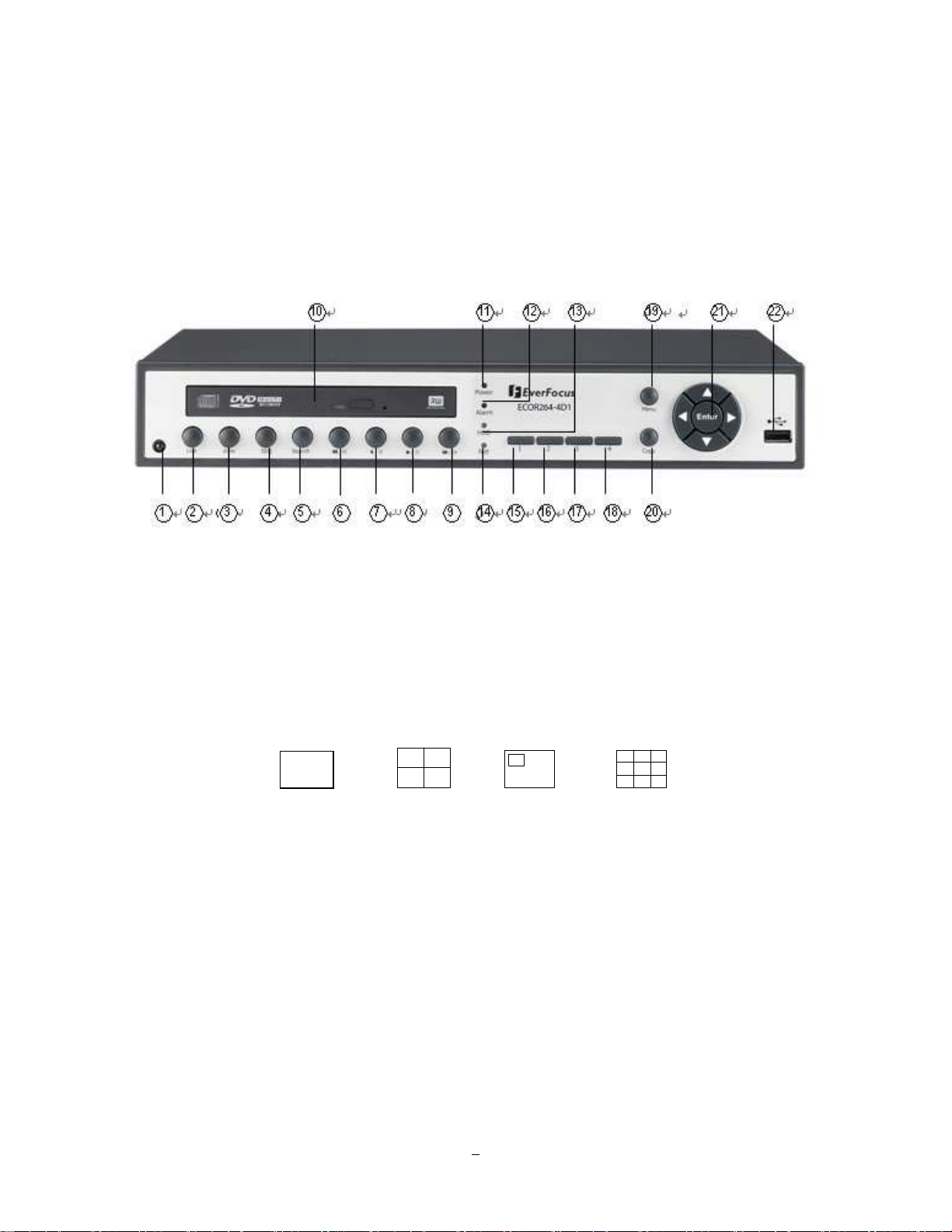
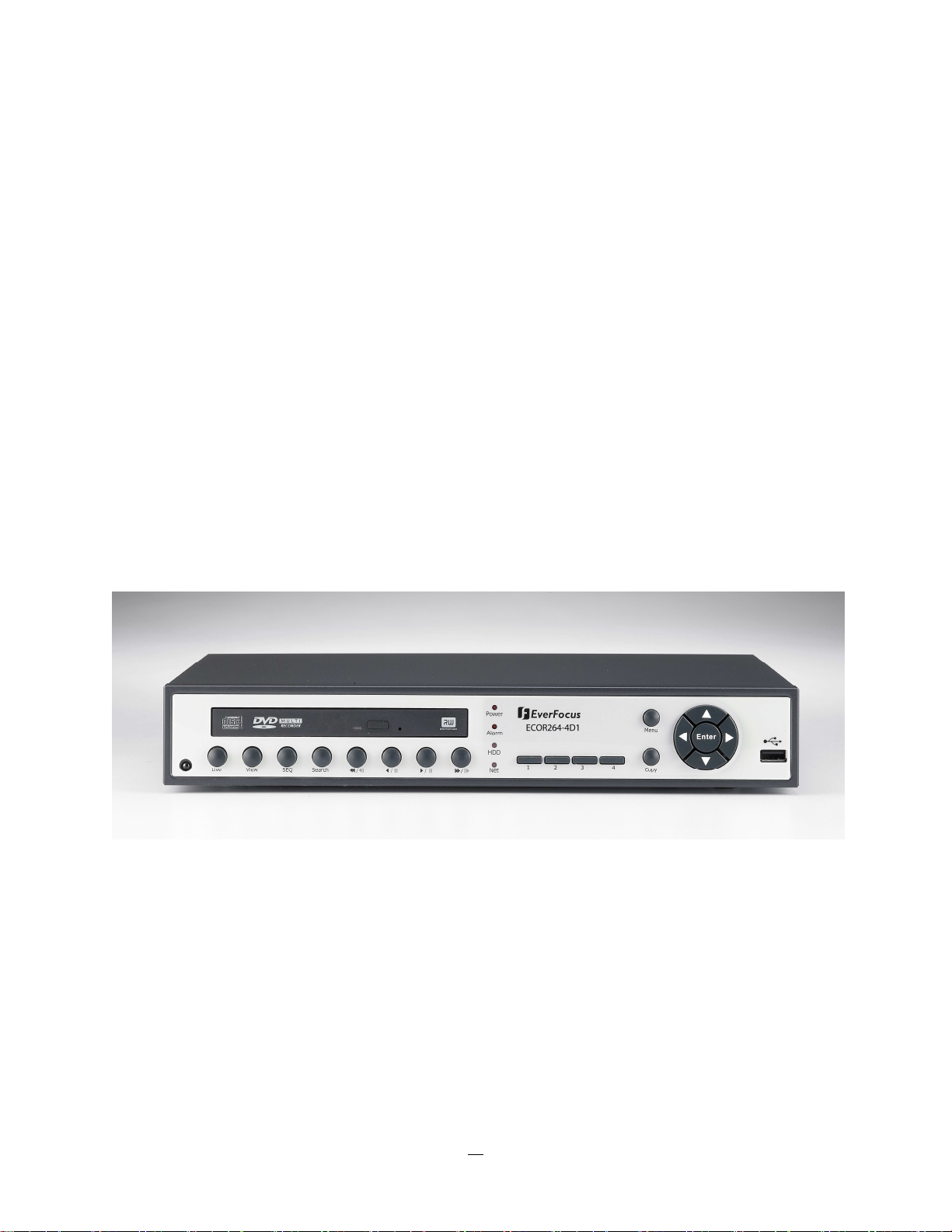
1.4 FRONT PANEL
Your primary interaction with your new DVR will be through the Front Panel buttons and their
corresponding buttons on the included Remote Control. Take a moment to learn where the keys are as the
remainder of the manual will refer to them often.
Figure 1-1 Front Panel
1) IR Receiver: Receiver for IR remote control
2) Live: Press this key to show live view. Press to exit from playback mode.
3) View: Press this key to switch between 4x, PiP (Picture In Picture), and full screen and
9x. Examples of four different views are listed below:
4x PiP Full screen 9x
Note1: PIP display is not available in playback mode.
Note2: 9-screen display available in 8 Channel model only.
4) SEQ: Press this key to enter the auto sequential switching mode. The sequence dwell
time can be set in “Display Setting” tab of the Menu. For more detail about SEQ,
please see “Section 4.8.2 Display Setting-Main M/T SEQ”.
5) SEARCH: Press this key to enter Search Menu. For more detail about the Search function,
please see “Section 3.12 Search ”.
4
Page 13

6) ◄◄/◄I: Fast reverse playback or step reverse playback depending on playback mode.
7) ◄/ I I: Reverse playback or pause
8) ►/ I I: Forward playback or pause
9) ►►/I►: Fast Forward playback or step forward playback depending on playback mode.
10) DVD+RW: DVD+RW burner (D models only)
11) POWER LED: This LED ON indicates Power on.
12) ALARM LED: This LED ON indicates Alarm active.
13) HDD LED: This LED ON indicates HDD active.
14) Net LED: This LED ON indicates Network active.
15~18) Channel keys 1~4 (1~8): Press channel key (CH1~CH4) / (CH1~CH8) to display that channel in
full screen view.
19) MENU: Press this key to enter/exit MAIN SETUP MENU.
20) COPY: Press this key to enter Copy Menu. For more detail about Copy function, please
see “Section 3.13 Copy”.
21) ENTER/ ARROW keys: Instead of or in combination with a mouse, you can use these keys to
change the Menu settings.
22) USB 2.0 port: For connecting USB-Flash-Drive to copy/archive video or for firmware upgrades.
5
Page 14
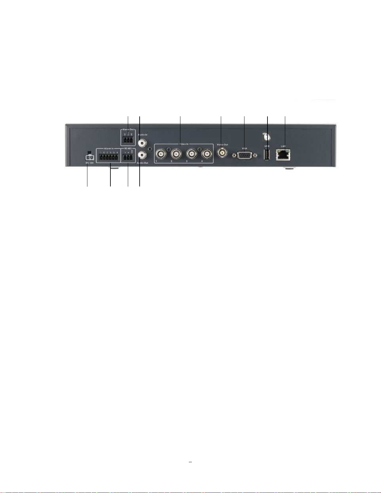
1.5 REAR PANEL
During initial setup you will be connecting your DVR to multiple input and output devices. This is done
through the rear panel.
○3 ○9
○5 ○7 ○8 ○10 ○11
○1 ○2
○4 ○6
Figure 1-2 Rear Panel
○○○○1 POWER: Plug the DC 12V power source provided into the power socket.
○○○○2 Alarm In: Connect up to 4 alarm inputs, selectable between N.O./N.C. contacts or can accept
TTL/CMOS signal polarity.
3
○○○○
Alarm Out: N.C or N.O type alarm out (form “C”).
○○○○4 RS485 socket: For remote control via RS-485 keyboards and telemetry control for attached PTZ
devices
5555
○○○○
Audio In: Connect a line level audio mixer output/source to the audio input connection.
○○○○6 Audio Out: Connect the input of a line level audio amplifier to the audio output connection.
○○○○7 Video In: Connect camera’s video output or other composite video source to the video input
connection.
○○○○8 Video Out: Main monitor - connect a CCTV monitor to the video output connection.
○○○○9 VGA: Main monitor - connect a VGA monitor to the VGA output connection. VGA resolution is
1024x768.
○○○○10 USB 1.0: USB port recommended for connecting the USB mouse.
6
Page 15

○○○○11 LAN: RJ-45 network connection 10/100Mb/s Ethernet. There are two LEDs on the LAN jack;
Green LED means network is connected, amber LED flickers when data is being exchanged.
1.6 VIDEO INPUTS/OUTPUTS INSTALLATION
Camera and CCTV monitor must use 75 Ohm video cable (e.g. RG-59, RG-6, RG-11) with BNC connectors.
To avoid impedance mismatch and undesired loss/reflections, 50 Ohm coax cable (e.g. RG-58), antenna
cable and other types of coaxial cable are not compatible.
All connected video sources must provide a 1 Vpp NTSC or PAL standard video signal.
When converting transmission lines (twisted pair, fiber optics, radio) to the video inputs, be sure to verify
accurate receiver calibration and signal levels.
ATTENTION: In order for the system to auto-detect the appropriate video format (NTSC or PAL), make
sure that there is a video signal on video input 1 upon power-up.
1.7 AUDIO INSTALLATION
This DVR provides 1 audio input and 1 audio output.
ATTENTION: The direct connection of a non-amplified microphone is not supported (a microphone
amplifier is required).
The installation must be done with audio coax cable and RCA plugs.
AUDIO RECORDING FUNCTIONALITY:
Audio recording is activated / deactivated in the Camera Menu for Camera #1. Please check and always
comply with local laws and regulations when using audio recording.
The audio channel is always recorded together with video and is independent of the image recording rate.
Though the audio record control is done in the Camera #1 screen, there is no specific camera allocation.
1.8 ALARM CONTACTS INSTALLATION
The alarm inputs can be used to start recording or for recording rate adjustment. In addition, alarm
reactions such as camera display on the monitor, buzzer, e-mail and network alarm are available. The
alarm output relay can be switched if required. Alarm input response actions can be controlled according to
a flexible schedule.
7
Page 16
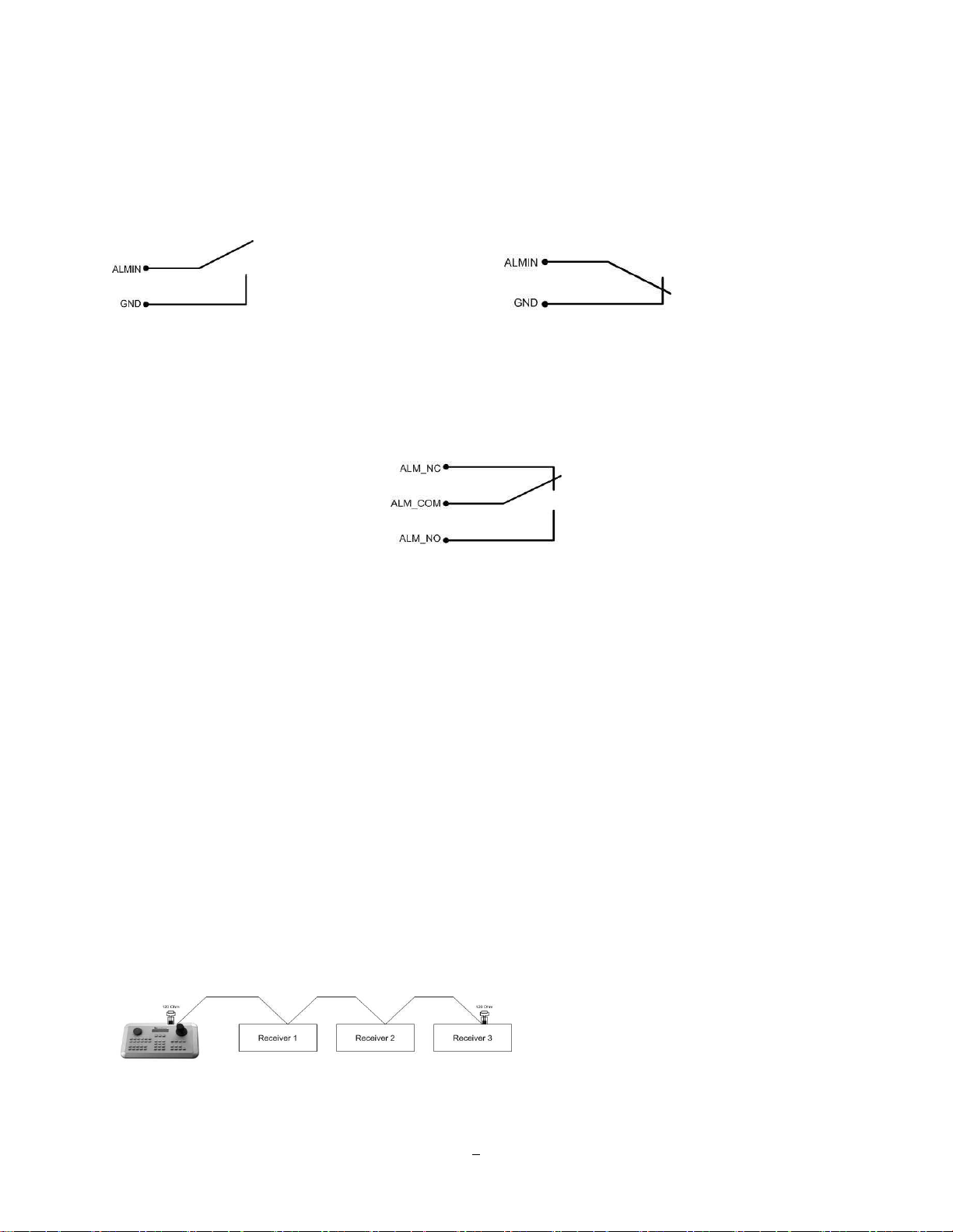
1.8.1 Alarm Input Contacts
This DVR provides one alarm input per camera. All inputs are programmable N.O. (Normal Open) or N.C.
(Normal Closed) Inputs have to be switched by dry contacts.
Alarm input with N.O. (Normal Open) contact Alarm input with N.C. (Normal Closed) contact
in idle state in idle state
All settings are programmed in the ALARM menu (Section 0).
1.8.2 Alarm Output Relay
The relay output provides either Normally Open or Normally Closed dry contacts.
Output relay in idle state
1.9 RS-485 keyboard / PTZ Installation
All functions can be remote-controlled by the EKB-500 universal keyboard. Using the EEPbus protocol,
digital video recorders, keyboards and speed domes can be installed on one single RS-485 bus. One
system can comprise up to 8 keyboards.
1.9.1 General RS-485 bus installation
The EKB-500 keyboard uses a RS-485 simplex wiring; the signal is transferred via a single twisted pair line.
CAT5 network cable is recommended, UTP version (unshielded) is sufficient for normal applications. A
shielded cable should be used if the installed cables are expected to be highly susceptible to interference.
The number of devices installed in one bus is limited to 32, and the maximum cable length is 3,900 feet.
Both of these can be expanded using a signal distributor (see below).
Both the first and the last device in series should be terminated with 120 Ohm resistance in order to
minimize line reflections.
RS-485 bus serial wiring
8
Page 17
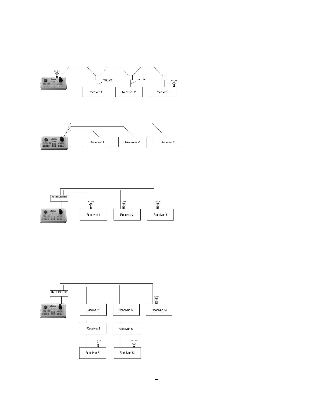
Cable length from box to device („Stubs“) has to be limited to 2m using connector boxes.
RS-485 bus serial wiring with connector boxes and connection cable
A direct RS-485 bus star wiring is not supported unless using a signal distributor (see below).
Improper RS-485 bus star wiring
A RS-485 signal distributor may be used to use a star wiring configuration.
Star wiring with RS-485 signal distributor
A RS-485 distributor can also be used to increase the maximum number of devices on the bus as well as
the total range. Each distributor output provides another RS-485 bus. This allows each output to extend an
additional 1200m, and it also enables the additional connection of 31 further devices to each output (the
output itself represents one device).
The maximum system expandability depends on the RS-485 address range of the installed devices.
9
Page 18

System expansion with RS-485 signal distributor
ATTENTION: Most signal distributors are unidirectional! This means that the signal only flows from the
input towards the outputs. Therefore, e.g. the interconnection of several keyboards is not possible with
these types of signal distributor!
1.9.2 RS-485 socket pin assignment
The RS485 pin assignment is as follows:
1.9.3 EKB-500 connection with network patch cable
For a simple, short distance installation, recorder and keyboard can be connected directly using a standard
CAT5 network cable with an 8-pin connector at only one end, and at the other end the Pin 3 wire connected
to RS485 “+” (plus) and the pin 6 wire connected to RS-485 “-“ (minus).
1.9.4 EKB-500 connection to several DVRs
For long distance installations connecting several DVRs, please use a signal distributor to connect
For further details on keyboard connection, please refer to the EKB-500 manual.
RS-485 port communication settings are configured in the I/O CONTROL menu (Section 5.10.4 System
Setup: I/O - control).
1.9.5 Speed Dome Installation
Speed dome or telemetry receiver pan/tilt/zoom control is available through web browser or the optional
PowerCon software if the DVR is connected to a network. Local telemetry control is provided by USB mouse control or by the optional EKB-500 keyboard.
Supported protocols: EverFocus, Pelco-D, Pelco-P, Samsung, Transparent
Required DVR settings: RS-485 receiver address in CAMERA menu
(Section 4.3)
RS-485 parameters and protocol in the I/O CONTROL menu
(Section 5.10.4)
ATTENTION: Some Pelco-D / -P protocol domes and receivers require an address offset of -1, i.e. the
address assigned to the dome / receiver in the DVR camera menu must be 1 below the address set in the
dome / receiver itself!
10
Page 19
1.10 USB-Mouse installation
Connect the USB mouse to one of the 2 USB ports. (This can be done while DVR is powered on) The rear
USB V1.0 port is recommended to reserve the higher speed front USB V2.0 port for video copy/export.
NOTE: Recommended mouse types are Logitech® and Microsoft® wired USB wheel-mouse. Wireless
USB mouse is not supported.
1.11 NETWORK CONNECTION
This section only describes physical connection to an Ethernet network. This step must be completed
before the DVR can connect to the network. There are two basic types of connection:
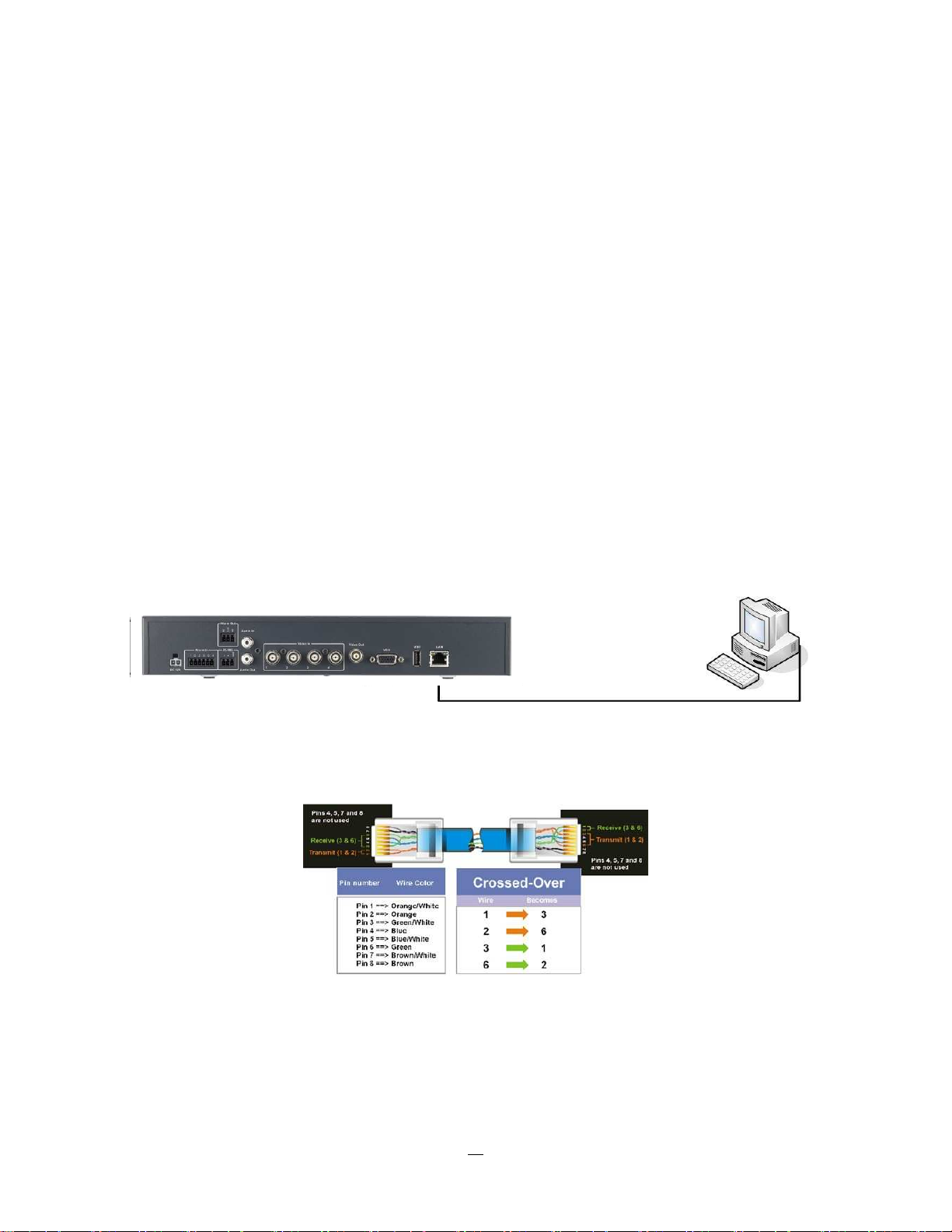
1.11.1 Direct PC Connection through Crossover Network Cable
The point-to-point connection of DVR and PC requires a crossover (crossed) network cable. This type of
connection is ONLY used for direct connection to a single PC. Make sure that the PC is equipped with a
10/100/1000 Mbps compatible network connection.
Figure 1-3 Direct PC Connection
Pinout of crossover-cable
11
Page 20
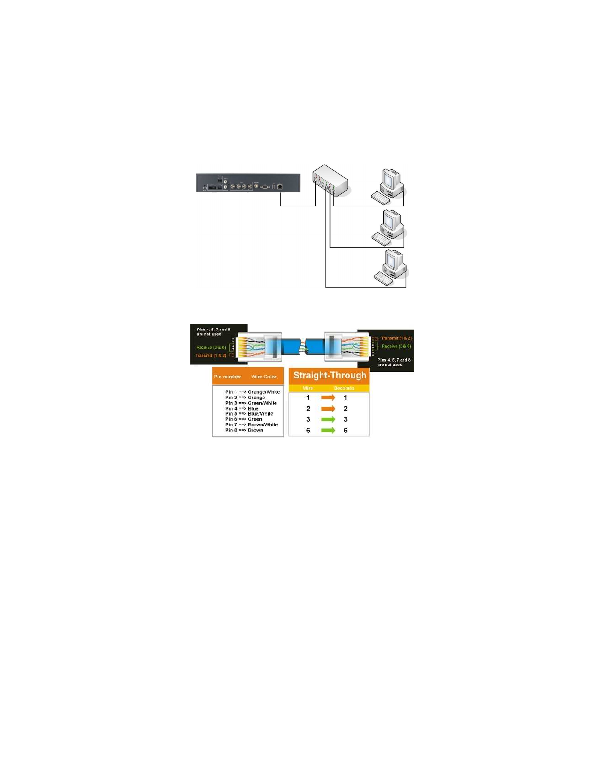
1.11.2 Network Connection through Patch Cable
The connection to an existing network requires a normal patch cable (straight-through). The illustration
shows the connection to a network switch or router.
Figure 1-4 Network Connection through Patch Cable
Pinout of straight patch cable
1.12 FINAL INSTALL PROCESS
Once you have completed the basic wiring connections, you are ready to turn on the DVR. Simply plug in
the power source. The POWER LED will light up if power is normal. Once the system has finished loading,
you can begin to set up the menu options for the DVR.
12
Page 21
Chapter
3
2 MOUSE AND FRONT PANEL OPERATION
ECOR264-4/ECOR264-8 DVRs support multiple sources to control the DVR. It can be controlled with a
mouse, the front panel, an EKB500, and the handheld remote control.
This chapter will cover the basic operation using the mouse and the front panel buttons.
2.1 GENERAL USB MOUSE OPERATION
2.1.1 How to select a channel / Enable audio
1. In a view consisting of more than one channel, users can select a channel by clicking once on the
desired channel screen. The selected screen will be highlighted by a white frame.
2. Double clicking on a channel screen will display full screen for this channel.
3. To enable audio out, click the audio icon (ex: ) at lower side of the screen. This system has only
one audio out. Click this button to enable or disable the audio-out mode.
2.1.2 OSD Root Menu
1. Right-click the mouse to obtain the DVR control bar (see Figure 2-1 OSD Root Menu ). When you move
the mouse over each icon, its title will be displayed at the top of the control bar.
Figure 2-1 OSD Root Menu
2. Click on any icon to perform that action. These actions are covered in detail in Chapter 3.
3. Click the “X” in the top-right corner to close the DVR control bar.
2.1.3 Operation in the Configuration Menus
13
Page 22
Click on the icon to access the Configuration Menu.
The Configuration menu screens (shown in Figure 2-2 OSD Menu) are divided into 3 main sections.
1
○
2
○
3
○
Figure 2-2 OSD Menu
○1 In section 1, there are ten setup options available. Move the mouse over an icon and click to select it.
○2 In section 2, the categories for the selected icon will be displayed. Click on a choice to select it.
○3 In section 3, all the options for the selected choice will be available. Click on a field to make changes.
2.1.4 Field Input Options
The following are examples of different types of fields available in the Configuration menu.
Textbox: Click on the box and an on-screen keyboard will appear*. (see
note about the on-screen keyboard below)
Dropdown box: Click on the down arrow to see all selections, then
directly click on an option to select it.
Check box: Click on the box to enable it (checked) or disable it (unchecked).
Button: Click the button to execute the function.
14
Page 23
Bar: Click and hold on the bar to adjust the set point Left or Right.
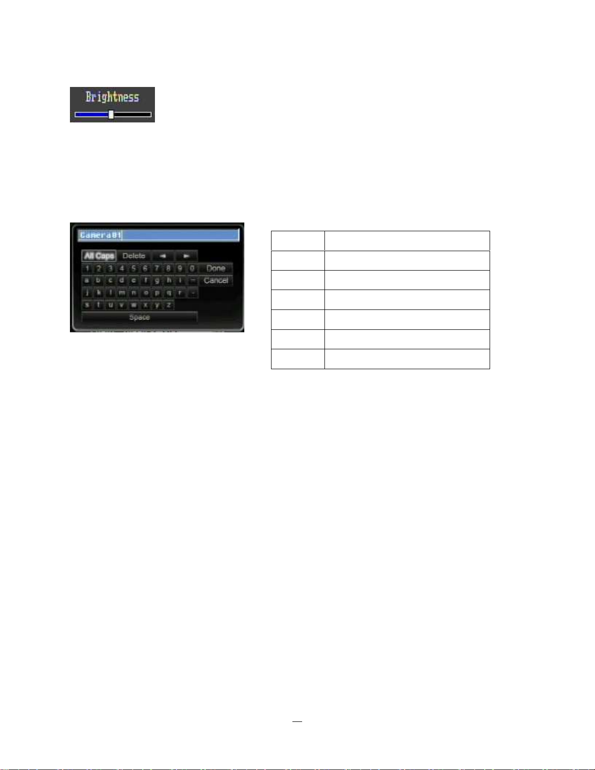
* Note about on-screen keyboard:
Click on a button to input that character.
The buttons on the right and bottom have the following functions:
Delete Delete the letter
Done Confirm the selection
All Caps Switch to capital letters
Space Enter a space
← Move to left
→ Move to right
Cancel Cancel and exit from the keyboard
.
15
Page 24
2.2 General Front Panel Operation
2.2.1 How to select a channel / Enable audio
1. In a view consisting of more than one channel, use the mouse or press arrow keys
(Up/Down/Right/Left) to scroll through each channel that is displayed. The selected channel will be
highlighted by white frame. Pressing the “right” arrow when the last camera (4 or 8) is highlighted will
select all cameras.
2. While channel #1 is selected, press the “Enter” button to turn Audio On/ Off.
2.2.2 OSD Root Menu
1. Press “Menu” key to display the DVR control bar. Use the left/right arrows to scroll over each icon. The
title for each icon will be displayed on top of the control bar.
2. Press “Enter” key on any icon to perform that action. These actions are covered in detail in Chapter 3
3. Press “Menu” to close the DVR control bar.
2.2.3 Front Panel Key Review
The basic principle of front panel operation is to use arrow keys to navigate among the menu items. Use
the “Enter” key to confirm a selection or enter the next level menu. Press the “Menu” key to enter the Main
Menu or exit from the current level of the menu.
2.2.4 Operation in Configuration Menu
Press “Menu”, use the arrow keys to highlight the “Configuration” icon, and press “Enter” with
“Configuration” icon highlighted to bring up the Configuration menu.
NOTE: If the require password option is active, you will need to log in first. Refer to “Section 3.2 LOGIN” for
information on logging in. The menu (shown in
Figure 2-3 OSD Menu
16
) is divided into 3 main sections.
Page 25
1
○
2
○
3
○
Figure 2-3 OSD Menu
○1 In section 1, there are ten setup options available. Use arrow keys to highlight an icon and press “Enter”
to select it.
○2 In section 2, the main choices for the selected icon will be displayed. Use Up/Down arrow keys to
highlight a choice and press “Enter” to select it.
○3 In section 3, all the options for the selected choice will be available here. Use arrow keys to move
between items and press “Enter” to make changes.
Note: press “Menu” button to go back to the previous menu section.
2.2.5 Field Input Options
Textbox: Press Enter key and an on-screen keyboard will appear*. (see
note about on-screen keyboard below)
Dropdown box: Press “Enter” key to show the available options. Use
arrow keys to highlight the desired option and press “Enter” again to select it.
Check box: Press “Enter” key on a setting to enable it (checked) or disable it (unchecked).
Button: Press “Enter” key to execute the function.
17
Page 26
Bar: Press “Enter” key to activate the slider, then use arrow keys to adjust the setting.
Press “Enter” again to finalize the changes.
* Note about on-screen keyboard:
Click on a button to input that character.
The buttons on the right and bottom have the following functions:
Delete Delete the letter
Done Confirm the selection
All Caps Switch to capital letters
Space Enter a space
← Move to left
→ Move to right
Cancel Cancel and exit from the keyboard
18
Page 27
Chapter
3
3. GENERAL DVR OPERATIONS
This chapter introduces the operations on major functions including playback, layout change, sequence,
triplex operations, copy, and search.
3.1 RECORD
By default, the DVR will always be in record mode. When the DVR is turned on, it will start to record. The
exceptions are:
1. DVR will not record any uninstalled cameras (Refer to Section 4.3.1 for more details)
2. If a schedule is active, the DVR will follow the record settings of the schedule.
3.2 LOGIN
In order to access ECOR264-4/ECOR264-8 options, users may be asked to log in for authority
identification. To log in, follow these steps.
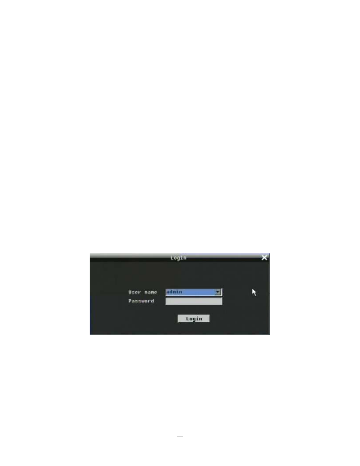
1. Right click on the screen or press the Menu Key to display the Main Menu
2. Choose or click (or press “Enter” key) on the Configuration icon to bring up the following screen:
Figure 3-1 Login page
3. Select the user name from the drop-down list and input the password. The defaults are:
User name: admin (lower case)
Password: 11111111
+ To input password by mouse: click the password field to bring up the on-screen keyboard (see Figure 3-2
On-screen Keyboard). Click on each button to input the desired characters for the password. When finished,
click “Done” on the on-screen keyboard to confirm the password.
19
Page 28
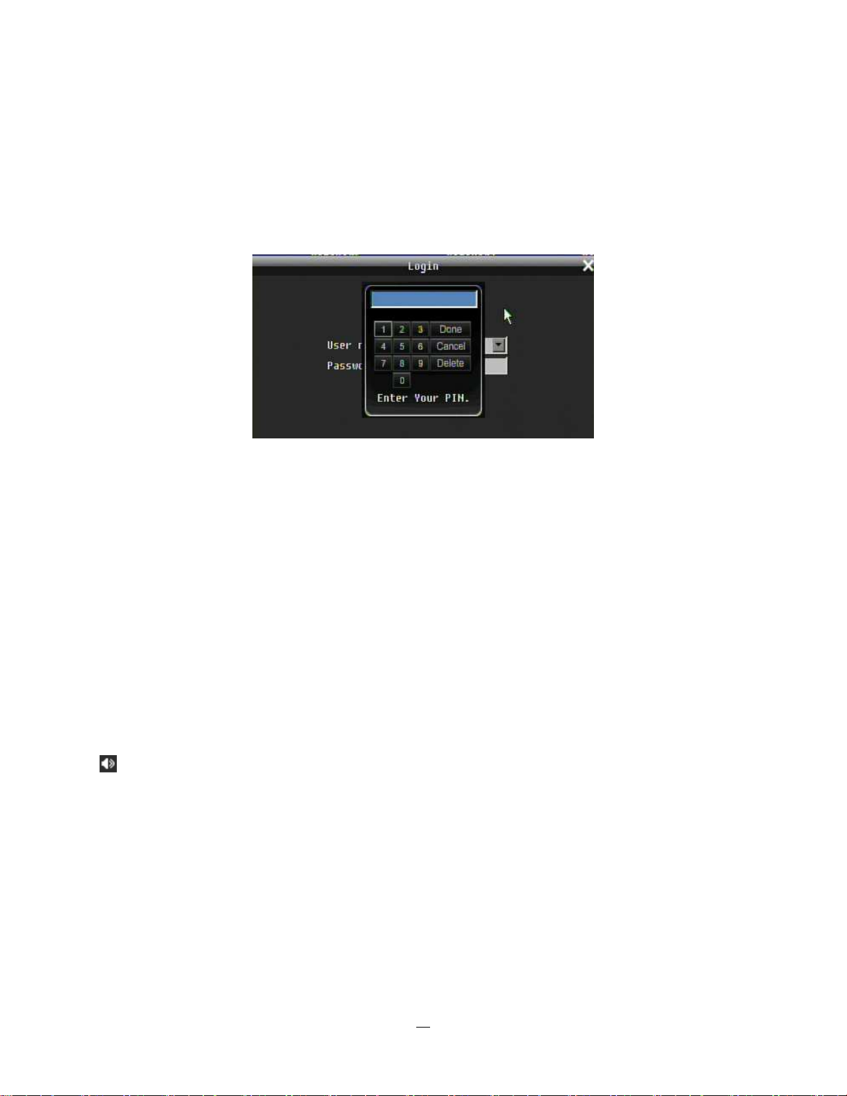
+ To input password using front panel: press “Enter” key to show the on-screen keyboard (see Figure 3-2
On-screen Keyboard). Use the arrow buttons to highlight each character and press the “Enter” key on the
front panel to input the selected characters. When finished, highlight “Done” and press the “Enter” key on
the front panel to confirm the password.
+ Click (or press “Enter” key) on the “Login” button to log in to the system.
Figure 3-2 On-screen Keyboard
3.3 SELECT CAMERA OPERATION
ECOR264-4/ECOR264-8 is a pentaplex DVR; users can control each camera individually by selecting that
camera. For camera selection:
Mouse: Right-click the screen, the image will show a white frame on screen if the camera has been
selected. When in quad display mode, press the quad layout icon in layout menu to select all four cameras.
4. Front panel: Use the arrows to change the selection. Pressing the “right” arrow when the last camera
(4 or 8) is highlighted will select all cameras.
3.4 CHANGE AUDIO OUTPUT OPERATION
Use arrow keys to select camera #1 and press “Enter” key to switch audio output on and off. An audio icon
will appear on the screen. Please make sure “Record Audio” option under Camera 1 Basic Settings
setup menu is ON if audio recording is required. Also, the audio source and/or audio output amplifier have
to be connected properly in order to utilize the audio functions. Note: Only Cam#1 controls audio, all others
do not control audio.
3.5 PLAYBACK
The playback bar is the fastest way to show video from the exact time which users want to see. The
playback bar allows a user to see both a time line and the current playback indicator. The user can then
click the time line to move the indicator to the position which they want to see. The operation is as follows:
20
Page 29

1 2 3 4
5 6 7 8
9 10 11 13
12 10 10
15 16
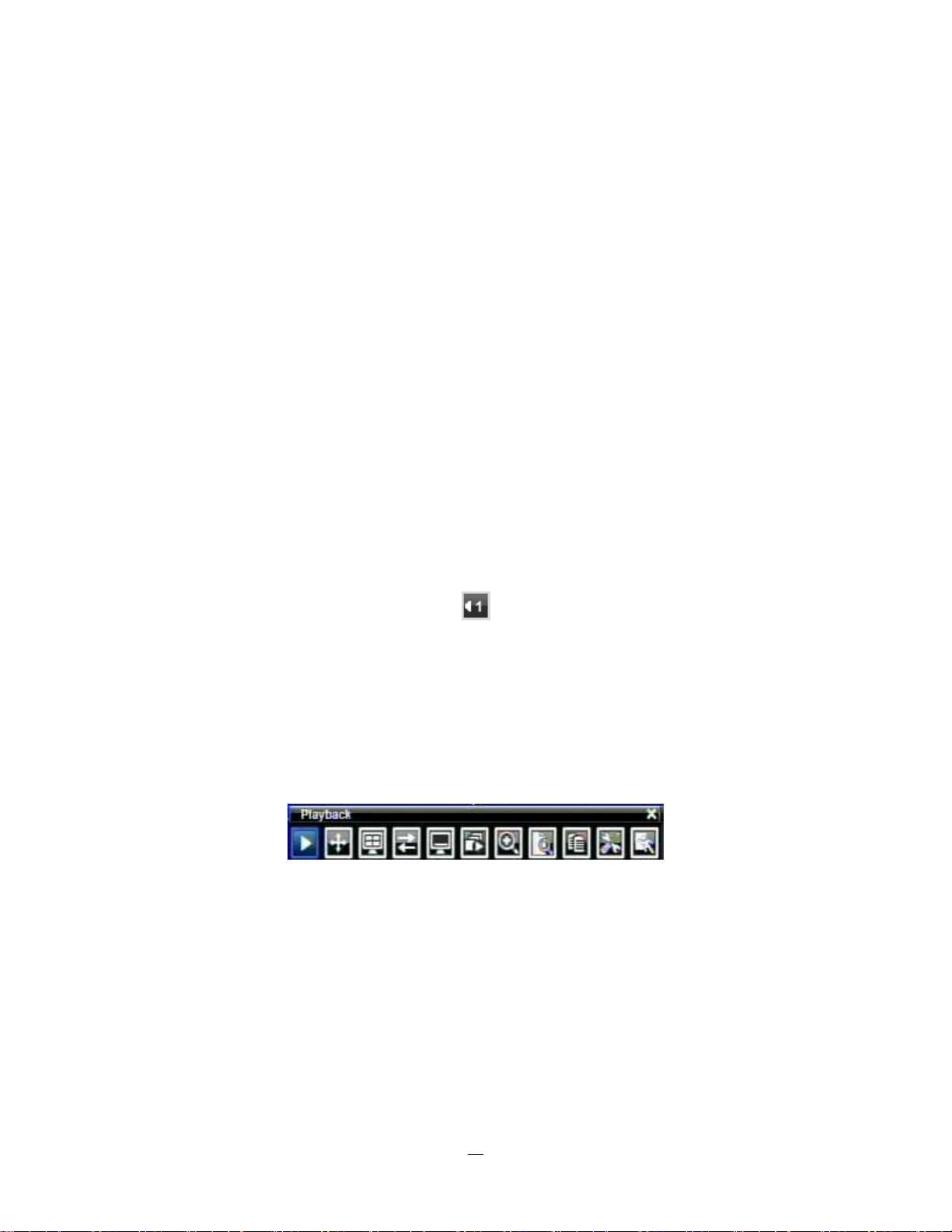
To playback:
By mouse: Right-click to bring up the menu bar and click on to enter Playback Menu.
By front panel: Press
key to enter Playback Menu.
The playback bar will show (see figure below):
2009/05/25 09:09:30PM 2009/05/25 09:09:40PM 2009/05/25 09:10:30PM
14
1. Stop key: press to stop playback
2. Slow Reverse key: press to start slow reverse playback
3. Pause key: press to pause playback
4. Slow Forward key: press to start slow forward playback
5. Fast Reverse key: press to start fast reverse playback
6. Reverse key: press to start reverse playback
7. Forward key: press to start forward playback
8. Fast Forward key: press to start fast forward playback
9. Time bar: Move the slider on the time bar to the select time to playback (The start time and end time for
time bar appears below the bar). The status of each camera is represented by different colors on the
time bar. Green means normal; orange indicates a Motion; blue indicates Video Loss, red indicates an
alarm event.
10. “+” and “-“ signs are used to adjust the time scale range for the bar. Press “+” or “-“ to select between
scale levels L1 ~ L5. When changing level, the start time and end time of the time bar will change)
L1: Entire time bar is 2 days
L2: Entire time bar is 30 hours.
L3: Entire time bar is 1 hour.
L4: Entire time bar is 10 minutes.
L5: Entire time bar is 1 minute.
11. Express copy: Press to start express copy when camera during playback (only one camera)
12. Playback speed indicator
13. Press “X” to close the playback bar.
21
Page 30
14. Start time for bar (the left-most point of the time bar)
15. Current playback time (the time indicated by the slider)
16. End time for time bar (the right-most point of the time bar)
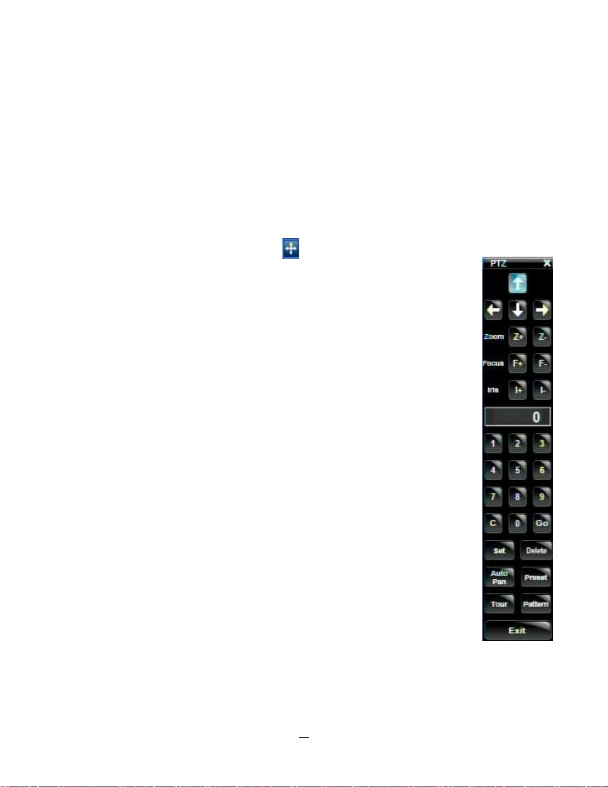
3.6 PTZ
3.6.1 General PTZ control
(if PTZ cameras are installed)
Right-click to bring up the menu bar and click on to display PTZ Controls.
The following actions can be performed using the PTZ Menu:
1. Use Direction Arrows (up, down, left, right) to move the camera to the desired direction
and angle.
2. To Zoom, Click “Z+” to zoom closer or “Z-” to zoom farther away.
3. To Focus , click “F+” to focus far or click “F-” to focus near.
4. With Iris, you can increase the amount of light by clicking “I+” or decrease it by clicking “I-“.
5. To program a preset position (if supported by the camera)
a. Move PTZ camera to the specified position
b. Click “Preset” button
c. Click the number of the desired position (This will be displayed in the box)
d. Click “Set” button
6. To jump to a preset position
a. Click “Preset” button
b. Click the number of the desired position
c. Click “Go” button
7. Shortcut for presets #1-9
a. Click digit 1-9 button without clicking any other buttons
b. The camera will seek that preset position
8. Steps to delete a preset position (if supported by the camera)
a. Click “Preset” button
b. Click the number of the desired position
c. Click “Delete” button
9. For Auto Pan
a. Click “Auto Pan” button
10. Pattern Operation (Pattern is the “0” Tour in Everfocus and Pelco PTZ cameras)
a. Click “Pattern” button
11. Steps to run a tour
a. Click “Tour” button
b. Click the number of the desired tour
22
Page 31

1 2 3 4
5 6 7 8
9 10 11 12
16 15 14 13
c. Click “Go” button
12. Steps to remove a tour (if supported by the camera)
a. Click “Tour” button
b. Click the number of the desired tour
c. Click “Delete” button
Click “C” to clear the digit in the number display
Click “X” at the top-right corner to hide the PTZ menu (see Express control below)
Click “Exit” to leave PTZ function.
3.6.2 Express Control of PTZ
If the PTZ control panel/menu has first been opened and then hidden, the mouse can be used to control
basic PTZ functions (Quick Mouse Control). The mouse cursor will change to different icons in different
areas of the screen. With Quick Mouse Control, the user can control PTZ direction, zoom, and focus by
clicking directly on screen. The screen is divided into 16 areas, with the outer ring is divided into 12 zones
used to control movement direction. The inner square of 4 areas is used to control zoom and focus.
Focus +
Focus -
Figure 3-3 Express Control PTZ
Zoom +
Zoom -
The screen is divided into a 4x4 grid. The function of each section is defined as below:
• 1: PTZ pan/tilt left and up
• 2, 3: PTZ tilt up
• 4: PTZ pan/tilt right and up
• 5, 9: PTZ pan left
• 8,12: PTZ pan right
• 13: PTZ pan/tilt left and down
23
Page 32

• 14, 15: PTZ tilt down
• 16: PTZ pan/tilt right and down
• 6: Focus closer
• 10: Focus further
• 7: Zoom in
• 11: Zoom out
REMEMBER:
Click “X” at the top-right corner to hide the PTZ menu (see Express control below)
Click “Exit” to leave PTZ function.
“X” only HIDES the PTZ control panel. “EXIT “ closes the panel and exits PTZ mode!! Other controls will not
respond until you EXIT the PTZ mode!!
24
Page 33

3.7 LAYOUT
The ECOR264-4/ECOR264-8 DVR has a total of three display modes available. The different available
layouts are shown below:
(Full) (4 screens) (PIP) (9 screens)*
NOTE: PIP display is not available in Playback mode
To change layout, follow the steps below:
By mouse: Right-click to bring up the menu bar and click then click on the desired layout choice.
By front panel: Push the “View” button on the front of the DVR to scroll through each display format.
Note: 9 screen view available only on 8 camera unit.
3.7.1 Bring to full screen mode
By mouse: Double left-click on the selected channel to put that camera in full screen mode.
By front panel: Press any channel key to bring that channel to full screen mode.
3.8 CHANNEL SWITCHING
Use this function to change channel position
1. Select one camera
2. Press Channel button .
3. Click on the channel number you wish to select on the channel bar. The display in that position will be
switched.
(four channel model example)
EX: Select camera1 and enter Channel menu and choose “2”, then camera 2 will show on position of
camera 1, camera 1 will show on position of camera 2.
25
Page 34

3.9 DISPLAY
1. Press Display button on menu by using mouse.
2. Press again to show status information. Please see the following table for status representation.
Recording Playback Fast forward Fast backward
Alarm Motion Video loss Express copy Audio out
3. Press again to show status information. Please see the following table for status representation.
Back pause
Alarm Audio Event
HDD failure
HD temp. too high
Seq.
Motion
Video loss
No network
4. Press again to show both status information and camera information.
5. Press again to hide all information.
3.10 SEQUENCE
1. By mouse: Click Sequence button to enter the auto sequential switching mode.
2. By front panel: Press the Sequence button on front panel to enter the auto sequential switching mode.
3.11 ZOOM
1. Make sure no camera is in playback mode
2. Select one camera
3. Right-click to bring up the menu bar and click button.
26
Page 35

1 2 3 4
5 6 7 8
9
10 11 12
16 15 14 13
4. When in ZOOM mode, the mouse cursor will change to a different icon in different areas of the screen.
Users can control the portion of the magnified image to be displayed by clicking directly on screen:
Figure 3-4 Zoom Express Control
The screen is divided into a 4x4 grid. The function of each section is defined as below:
• 1: Left and up
• 2, 3: Up
• 4: Right and up
• 5, 9: Left
• 8,12: Right
• 13: Left and down
• 14, 15: Down
• 16: Right and down
• 6, 7, 10, 11: Not used
3.12 SEARCH
By mouse: Right-click to bring up the menu bar and click to enter Search Menu.
By front panel: Press ”Search” key to enter Search Menu directly.
27
Page 36

3.12.1 Time Search
Figure 3-5 Search Menu – Time Search
Play From: Select the time to begin the search by choosing the Date and Time.
Click on the “Play” button to start the search. The DVR will automatically play the video being searched.
The DVR will play the nearest time if there is no data in selected time.
In search playback mode, press the “Stop” button to return to the search menu.
28
Page 37

3.12.2 Event Search
Figure 3-6 Search Menu – Event Search
From: Select starting date and time
To: Select ending date and time.
Camera: Select which cameras to search for.
Event: Select which event type(s) to search for. Choose from Alarm, Motion, Video Loss, or Others.
Click on the “Search” button to start searching. The search results will be shown as a list of events.
29
Page 38

Prev Page: Go to previous page
Next Page: Go to next page
Play: Playback selected item
Copy: Copy selected item
3.13 COPY
To bring up Copy menu:
By mouse: Right-click to bring up the menu bar and click on to enter Copy Menu.
By front panel: Press the “Copy” key to enter Copy Menu directly.
Figure 3-7 Copy Menu
Camera: Select which camera will be archived. Choose “Select All” to select all the cameras.
Player: Check the box to include the ePlayer program as part of the copy (recommended).
Start Date/Time: Select the starting date/time to be archived.
End Date/Time: Select the ending date/time to be archived.
30
Page 39

Archive To: Select whether you want to copy to USB or CD/DVD (CD/DVD on “D” models only).
Data Size: Shows the estimated total size for the time period.
Copy Now: Press “Copy” button to start archiving.
Eject: Press “Eject button to eject the CD/DVD. Eject button will only appear if media type is CD/DVD.
3.14 LOGOUT
Right-click to bring up the menu bar and click the button to bring up the Logout Confirmation
window (see Figure 3-8).
Figure 3-8 Logout Confirmation window
Press “Yes” button when you are ready to logout from the system. You will need to login again before
accessing any other options.
31
Page 40

Chapter
4
4 DVR CONFIGURATION
This chapter will walk you through the DVR Menu Settings step by step and show you how to set the DVR
for your specific application.
4.1 CONFIGURATION MENU
1. To bring up the Main Menu, press the “Menu” key on the front panel or right-click with the USB mouse
to bring up the OSD menu bar.
2. Press “Enter” or left-click on the “Configuration” icon “ ” to enter the Configuration Menu.
4.2 EXPRESS
The Figure 4-1 Express Menu is a screen shot of the EXPRESS SETTING MENU. This menu is used to
configure global express settings for all cameras. For example, if user selects Event Only in Record Mode
and presses the “Apply” button, all 4/8 cameras will be set to Event only. If user selects Blank in Recording
Mode and presses the “Apply” button, 4/8 cameras will keep their own current individual record settings
without any changes.
Figure 4-1 Express Menu
32
Page 41

Date: Sets the current date of DVR.
Time: Sets the current time of DVR.
Record Mode:
Normal+Event: Normal recording plus event recording.
Event Only: Event recording only.
Schedule Rec: Schedule recording.
Enter the number of hours per day for the estimated event recording.
Resolution: Select recording resolution based on video format.
NTSC: 720x480 / 720x240 / 360x240
PAL: 720x576 / 720x288 / 360x288
Record With:
Blank: No change to individual camera record settings
Preset Settings: Select preset setting or recording quality. Available options are Best Quality, Standard
and Extended Record in the next column. For more detail, please refer to APPENDIX B: RECORDING
VALUE SELECTION RULES
Recording Days: Set the maximum recording days. Available selection will be shown in the next column,
including 1, 3, 5, 7, 14, 20, 30, 40, 50 and 60 days. DVR will auto adjust relative settings for all the
cameras to fit the selected max recording days. For more detail, please refer to APPENDIX B:
RECORDING VALUE SELECTION RULES
33
Page 42

Network Type:
Fixed IP: User sets a fixed IP for network connection.
DHCP: DHCP server in LAN will automatically assign IP for network connection.
PPPoE: This is for direct DSL connection application ONLY (no router). Check with your ISP to see if
they use PPPoE.
IP Address: This field shows the current IP Address for the DVR. If Fixed IP address is used then this
value must be set manually. If DHCP or PPPoE is selected, this value will be assigned automatically.
Subnet Mask: This field shows the subnet mask for your network so the DVR will be recognized within the
network. If DHCP or PPPoE is selected, this value will be assigned automatically.
Gateway: This field shows the gateway for your network so the DVR will be able to communicate outside
the network. If DHCP or PPPoE is selected, this value will be assigned automatically.
DNS server 1: This field shows the primary DNS server for your network. When DHCP is selected and an
internet connection is available, this value will be assigned automatically. This field must be assigned
correctly if you plan to use the DDNS feature (see Section 4.6.3 DDNS for more details).
DNS server 2: This field shows the secondary DNS server for your network.
Note: The default addresses in the machine are for internal testing only. You must supply
your own addresses to comply with your network. Refer to Section 4.6 for more details.
Apply: Press “Apply” button to save and apply the Express settings to DVR. The system will automatically
adjust recording frame rate according to your settings. The following message will pop up; press “Yes” to
change Resolution, Recording frame rate and Quality depending on your Express settings.
34
Page 43

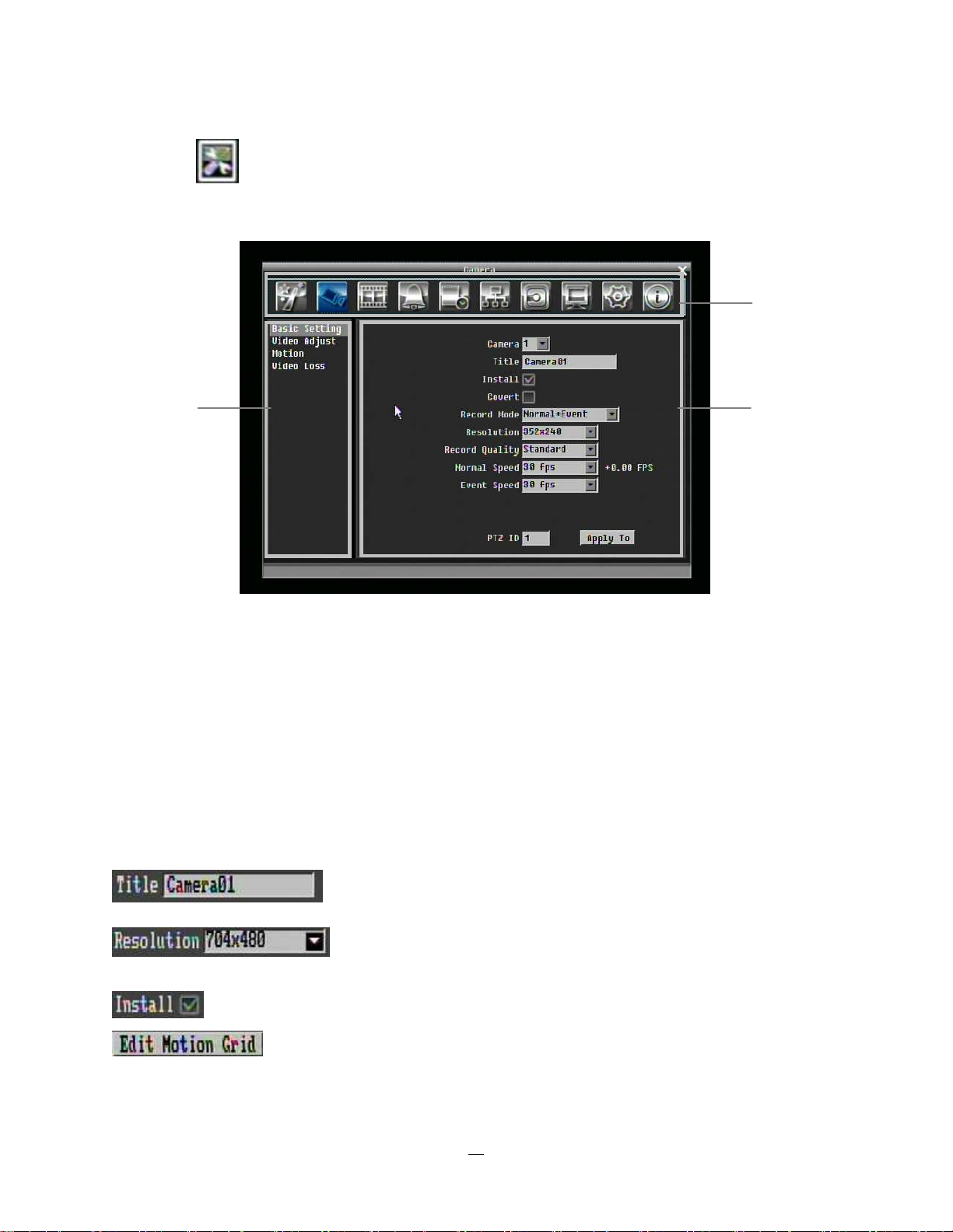
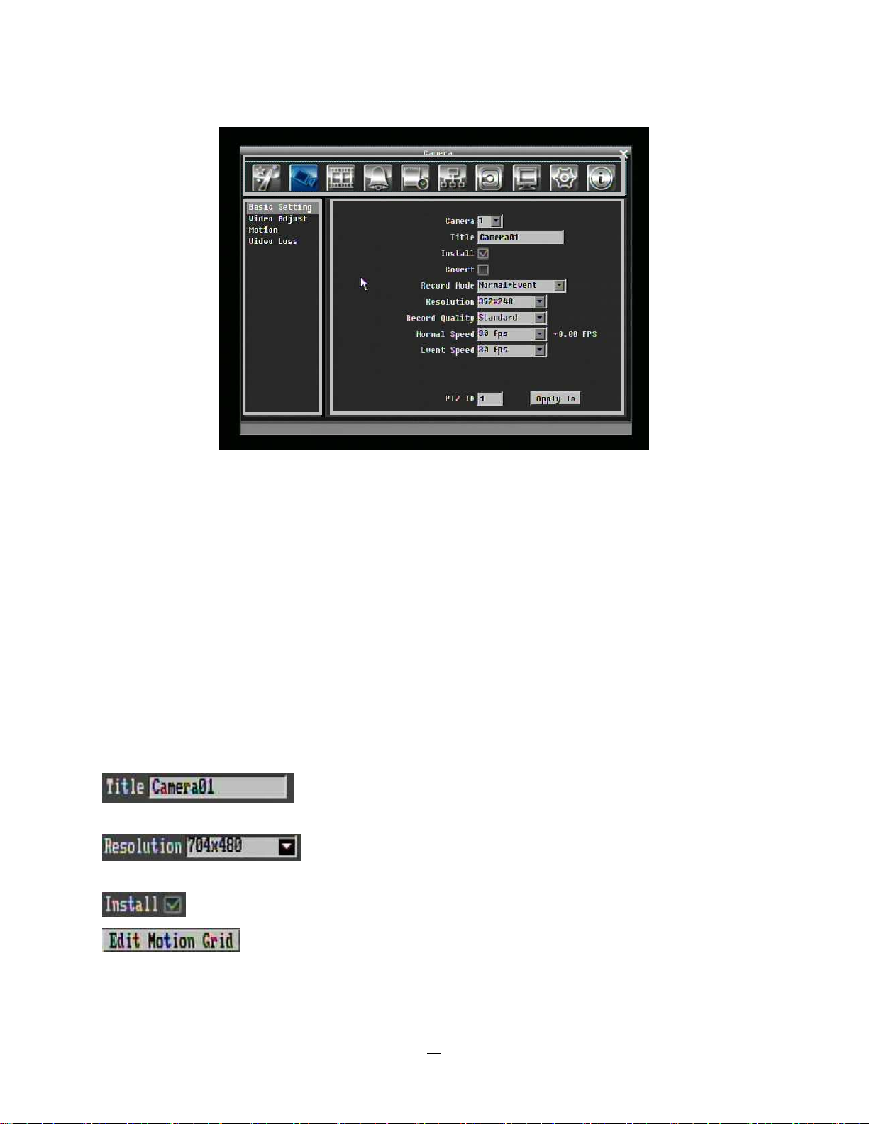
4.3 CAMERA SETTING
Figure 4-2 is a screen shot of the CAMERA SETTING MENU. This menu is used to configure individual
camera settings.
Figure 4-2 Camera Menu-Basic Setting
4.3.1 Basic Setting
Camera: Select the camera number.
Title: The title setting allows you to assign a title to selected camera. Each title supports up to 16
characters. The on-screen keyboard will appear when you click the title option.
Install: Check the box to enable the current camera. To take full advantage of the DVR’s recording abilities,
any unused cameras should have this option set to “disabled”.
35
Page 44

Covert: Check the box to hide the camera picture in live and sequence modes. However, the image will still
be recorded and can be played back by any user who has playback rights.
Record Mode: 2 record modes are available.
Normal + Event: This recording mode includes continuous and event recording.
Event Only: Video will be recorded only when events occur.
Resolution: Select recording resolution based on video format.
NTSC: 720x480 / 720x240 / 360x240
PAL: 720x576 / 720x288 / 360x288
Record Quality: Select an image quality for recording. There are five different qualities available: Superior,
High, Standard, Basic and Low. A higher image quality uses more HDD space.
Normal Speed: Frame rate in images per second (IPS) for continuous recording. The speed is limited to
the maximum recording rate of the DVR (displayed in the bottom left corner) divided by the number of
installed cameras. If the resolution option is changed, the unit of this field will also be changed.
Recording capacity for all cameras (shown next to the Normal Speed field): The number here indicates
the remaining recording capacity available for all 4 cameras. When this number is positive, it means
there is still recording capacity. If this number is negative, it means the recording capacity has been
exceeded, and the user must lower a Normal Speed recording rate or reduce the Resolution selected
(which allows the DVR to record more FPS). This number must be positive before saving the changes.
Otherwise, a pop-up window will display “Total FPS exceed maximum recording rate, discard changes!”
and the settings for all cameras will return to previous values.
Event Speed: Maximum desired frame rate in images per second (IPS) for event recording; if more than
one camera requires simultaneous event recording, the total for all cameras cannot exceed the maximum
available FPS for the DVR at that resolution setting, and the available FPS may be divided across the
cameras.
Record Audio: (Camera 1 screen only) Check this box to enable audio recording on the DVR.
PTZ ID: When using a PTZ Camera, in order to control the camera from the DVR this ID must match the
RS-485 ID used by the connected camera. Click “On” to confirm selection, “Off” to cancel PTZ control for
this camera. When PTZ ID is ON, a drop down menu will appear; set the PTZ ID address used to control
this camera in that menu.
Apply To: This button can be used to copy the recording settings to other cameras. Select which camera(s)
you wish to copy to. "Select All" selects all cameras, “Unselect All” deselects all cameras. Click “OK” to
copy the settings or "Cancel" to exit without copying.
36
Page 45

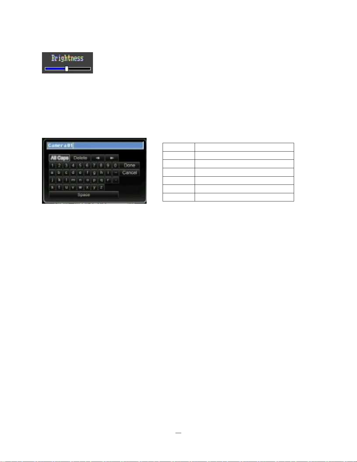
4.3.2 Video Adjust
Figure 4-3 Camera Menu – Video Adjust
Camera: Select the camera you wish to adjust. “Title” will change to the name of the selected camera.
Brightness: Adjusts how bright/dark the picture appears. If details appear to be lost in the shadows or
darker regions, try increasing the Brightness. If the image appears too saturated or if the colors appear
overwhelmed by glare, try decreasing the Brightness.
Contrast: Adjusts the total amount of light output from the display. If details are lost or lines appear
distorted, try decreasing the contrast.
Color: Adjusts the amount of color information in the picture.
37
Page 46

Apply To: This button can be used to copy the video settings to other cameras. Select which cameras you
wish to copy to. "Select All" selects all cameras, “Unselect All” deselects all cameras. Click “OK” to copy the
settings or "Cancel" to exit without copying.
4.3.3 Motion
Figure 4-4 Camera Menu – Motion
Camera: Select the camera you wish to adjust. “Title” will change to the title name of the selected camera.
Enable: Check box to enable motion detection. Other motion options will not be available unless this
feature is selected.
Log: Check this box to record motion events in the log.
Main Monitor: Monitor display options when a motion event occurs.
No change: No change on the main monitor display.
Full screen: A full screen of the event camera will display on the main monitor.
38
Page 47

Pre-alarm Record: Check box to start copying recorded video to the hard disk from several moments
before the motion event. (Pre-alarm recording rate will follow “Normal” frame rate setting)
Buzzer: Check this box to enable the buzzer when a motion event is triggered.
Email Notify: Check this box to send email notification when a motion event is detected. Email operation
requires that valid email settings have been entered in the Network Setting/Email setup screen
Network Alarm: Check box to send out a network alarm to client PC when motion occurs. (requires
PowerCon software and proper settings for the Alarm Server in the Network Setup menu)
Alarm Output: This will transmit a signal through the alarm output relay. It can be set to either “NONE” (not
active) or “1” (active).
Output Type: Output action when motion is triggered.
Timeout: Alarm output lasts for the set time duration.
Permanent: Alarm will remain on until user presses the “Enter” key on front panel or otherwise resets
the alarm condition.
Timeout Duration: Time duration selectable from 1 to 150 seconds.
Edit Motion Grid: Press this button to edit the motion grid (See Figure 4-5 Camera Menu – Motion Grid
Setting ).
Sensitivity: Set the threshold value for sensitivity within the grids. Select from 1 (lowest) to 10 (highest).
Min Area: To avoid false detections by small objects this value defines, how many grids have to be
exceed threshold before generating a motion event. Select a value between 1 (default) to 5 grids.
Preview: Preview the motion grid.
Set All: Press this button to select the entire area.
Clear All: Press this button to clear all the grids selected.
Save & Back: Press this button to save the motion grid setting and return to motion setting menu.
Cancel: Press this button to cancel all changes and returns to the motion setting menu.
How to select motion grid by mouse:
1. Select lower-right grid.
2. Select upper-left grid.
3. The area between upper-left and lower-right grid will be selected.
How to select motion grid by front panel:
1. Press Enter key to enter motion grid.
2. Use arrow keys to select one corner of desired area
3. Press Enter key at the starting point.
4. Use arrow keys to select motion area.
39
Page 48

5. Press Enter key twice at the end point, and the area will be selected.
Figure 4-5 Camera Menu – Motion Grid Setting
Apply To: This button can be used to copy the motion settings to other cameras. Select which cameras
you wish to copy to. "Select All" selects all cameras, “Unselect All” deselects all cameras. Click “OK” to
copy the settings or "Cancel" to exit without copying.
40
Page 49

4.3.4 Video Loss
Figure 4-6 Camera Menu – Video Loss
Camera: Select the camera you wish to adjust, “Title” will change to the title name of the selected camera.
Enable: Check box to enable Video Loss detection.
Log: Check box to record video loss events in the log.
Pre-alarm Record: Check box to start copying recorded video to the hard disk from several moments
before the video loss. (Pre-alarm recording rate will follow “Normal” frame rate setting)
Buzzer: Check box to enable buzzer when a video loss event occurs.
Email Notify: Check box to enable email notification when a video loss event occurs. Email operation
requires that valid email settings have been entered in the Network Setting/Email setup screen.
Network Alarm: Check box to send out a network alarm to client PC when video loss occurs. (requires
PowerCon software and proper settings for the Alarm Server in the Network Setup menu)
Alarm Output: This will transmit a signal through the alarm output relay. It can be set to either “NONE” (not
active) or “1” (active).
Output Type: Output action when alarm is triggered.
Timeout: Alarm output lasts for the set time duration.
Permanent: Alarm will remain active until user presses “Enter” key on front panel.
Transparent: Alarm output continues as long as there is a video loss.
Trans+Timeout: Alarm output continues until event ends, then continues for the set time duration.
41
Page 50

Apply To: This button can be used to copy the video loss settings to other cameras. Select which cameras
you wish to copy to. "Select All" selects all cameras, “Unselect All” deselects all cameras. Click “OK” to
copy the settings or "Cancel" to exit without copying.
4.4 RECORD & PLAY SETTING
Figure 4-7 is a screen shot of the RECORD & PLAY SETTING MENU. This menu is used to configure
basic recording and playback settings.
Figure 4-7 Record & Play Menu
4.4.1 Record
Record Overwrite: Check the box and disk will begin overwriting when full. NOTE: Unless this box is
checked, the DVR MUST STOP RECORDING WHEN THE DISK IS FULL. The use of record overwrite is
42
Page 51

strongly recommended. If you do not use this feature, please be sure to make specific arrangements to
monitor/be notified when the disk is full.
Schedule Record: Use schedule recording mode.
For Schedule recording, the only way to stop the DVR from recording is to turn schedule recording off.
Pressing any key on the front panel to attempt to stop recording will not work during scheduling record
mode. When schedule recording is disabled, as the default the DVR will automatically begin recording
when it is first turned on.
Time Stamp: Select if the time and date will display while recording. Choose the location for the time
display from Top, Bottom, or Off.
Record Status Relay Output: Select from “NONE” and “1”. When alarm output is connected, user can
easily see recording status from the alarm output if this option is set as “1”.
Auto Erase Video: The hard drive will automatically erase video after it has been on the hard drive for the
selected number of days. To use the maximum hard drive space, choose “OFF”. (See Record Overwrite
and notes above.)
4.4.2 Built-in Calculator
The built-in record period calculator can give a rough estimation of the total recording time for the DVR with
current settings. In order to compute as accurate an estimate as possible, please enter your estimates for
the hours per day you expect recording to take place due to motion events and due to other alarm
conditions.
Figure 4-8 Record & Play Menu-Built-in Cal.
Motion: Enter the expected number of hours per day due to motion recording.
43
Page 52

Alarm: Enter the expected number of hours per day due to alarm recording.
If the total Motion and Alarm hours is more than 24 hours, the calculator will assume that motion and alarm
recording take place for the entire 24 hour period.
E
S
T
I
M
A
T
E
Click on the “E
E
S
T
S
T
”
I
M
A
T
E
”
I
M
A
T
E
”
button to display the result at the bottom of the screen:
" xx days of data can be stored based on current setting"
4.4.3 Play
Figure 4-9 Record & Play Menu - Play
Quick Playback: Check the box to enable the quick playback function as described below.
Playback From X Seconds ago: When the DVR is put into playback (press PLAY), it will begin playing
from the selected time. Choose from 60 to 3600 seconds prior to the present time.
If Quick Playback is not enabled, pressing the PLAY button will bring up the Playback Bar (see Section 3.5).
44
Page 53

4.5 ALARM & EVENT SETTING
Figure 4-10 is a screen shot of the ALARM & EVENT SETTING MENU. This menu will walk you through
alarm and event setup.
Figure 4-10 Alarm & Event Menu - Alarm
4.5.1 Alarm
Alarm: Select the alarm input trigger connection number from 1 to 4/8.
Enable: Check box to enable response to that alarm trigger.
Log: Check box to record these alarm events in the log.
Pre-alarm Record: Check box to start copying recorded video to the hard disk from several moments
before the alarm event. (Pre-alarm recording rate will follow “Normal” frame rate setting)
Buzzer: Check this box to enable the buzzer when an alarm occurs.
Main Monitor: Monitor display options when a motion occurs.
No change: No change on the main monitor display.
Full screen: A full screen of the active camera will display on main monitor.
Record: Select which camera(s) will start recording in response to this alarm event.
Email Notify: Check box to enable email notification when an alarm occurs. Email operation requires that
valid email settings have been entered in the Network Setting/Email setup screen.
Input Type: This field is to change the type of alarm trigger.
45
Page 54

N.O.: Normal Open contact.
N.C.: Normal Closed contact.
Network Alarm: Check box to send out a network alarm to client PC when motion occurs. (requires
PowerCon software and setting up Alarm Server in Network Setup menu)
Active Camera: This field is for associating and alarm trigger with a specific camera. For example if you
had an external motion detector near camera four you would set this option to “4”. The alarm will be
associated with this camera for optional full screen display, event logging, and PTZ preset activation.
PTZ Preset: Select PTZ Preset from “1” to “255”. If the Active Camera is a PTZ speed dome, the alarm will
move the camera to the specified preset position for event recording. Click “On” to confirm selection, “Off”
to cancel selection. When “ON” a sub-menu is displayed for choosing the desired PTZ preset number.
Alarm Output: This will transmit a signal through the alarm output. It can be set to either “NONE” (not
active) or “1” (active).
Output Type: Output action when alarm is triggered.
Timeout: Alarm output lasts for the set time duration.
Permanent: Alarm will remain active until user presses the “Enter” key or resets the alarm remotely.
Transparent: Alarm output remains as long as the alarm input is active.
Trans+Timeout: Alarm output continues until event ends, then continues for the set time duration.
Timeout Duration: Time duration selectable from 1 to 150 seconds.
Apply To: This button can be used to copy the alarm settings to other cameras. Select which cameras you
wish to copy to. "Select All" selects all cameras, “Unselect All” deselects all cameras. Click “OK” to copy the
settings or "Cancel" to exit without copying.
46
Page 55

4.5.2 Event
This section covers notifications due to internal system event warnings.
Figure 4-11 Alarm & Event Menu – Event
Event: Select from the following event types.
HD Temperature: Hard drive is over the safety warning temperature
HD Failure: If DVR fails to detect the HDD on start up, the system will create an HD failure event.
HD Full: If the DVR is not set to Overwrite in the Record Menu, an event will be created when the HDD
is filled.
HD Off: If HDD are switched off or are removed, the DVR will create an HD OFF event.
Network Loss: If connection to the local network is lost, DVR will create a Network Loss event.
NOTE: This function only checks the physical connection (link) to the network. Any network behavior
that blocks data connectivity (blocked ports, IP addressing errors, etc.) is not detected by this function.
47
Page 56

HD Temperature:
Figure 4-12 Alarm & Event Menu – Event - HD Temperature
Log: Check box to record HDD temperature events in the log.
Buzzer: Check box to enable buzzer when hard drive’s temperature is over the “Temp. Warning Limit”.
Email Notify: Check box to enable email notification when HDD temperature is over the “Temp. Warning
Limit”. Email operation requires that valid email settings have been entered in the Network Setting/Email
setup screen.
Network Alarm: Check box to send out a network alarm to client PC. (requires PowerCon software and
setting up Alarm Server in Network Setup menu)
Stop Recording: Check box to stop recording when HD’s temperature is over the “Temp. Warning Limit”.
Temp. Warning Limit: Sets the trigger temperature for HD Temperature event actions. Choose between
55°C /131°F or 85°C /185°F.
Alarm Output: This will transmit a signal through the alarm output. It can be set to either “NONE” (not
active) or, “1” (active).
Output Type: Output action will be Transparent and cannot be changed (alarm output remains as long as
the alarm condition is active).
48
Page 57

HD Failure:
Figure 4-13 Alarm & Event Menu – Event - HD Failure
Log: Check box to record events in the log.
Buzzer: Check box to enable the buzzer if no hard drive is detected on system startup.
Email Notify: Check box to enable email notification function when HD fails. Email operation requires that
valid email settings have been entered in the Network Setting/Email setup screen.
Network Alarm: Check box to send out a network alarm to client PC. (requires PowerCon software and
setting up Alarm Server in Network Setup menu).
Alarm Output: This will transmit a signal through the alarm output. It can be set to either “NONE” (not
active) or “1” (active).
Output Type: Output action will be Transparent and cannot be changed (alarm output remains as long as
the alarm condition is active).
49
Page 58

HD Full:
Figure 4-14 Alarm & Event Menu – Event - HD Full
Log: Check box to record events in the log.
Buzzer: Check box to enable the buzzer when hard drive is full (recommended if the Record Overwrite
function is disabled. See Section 5.4.1).
Email Notify: Check box to enable email notification when HD is full. Email operation requires that valid
email settings have been entered in the Network Setting/Email setup screen.
Network Alarm: Check box to send out a network alarm to client PC. (requires PowerCon software and
setting up Alarm Server in Network Setup menu)
Alarm Output: This will transmit a signal through the alarm output. It can be set to either “NONE” (not
active) or “1”(active).
Output Type: Output action when alarm is triggered.
Timeout: Alarm output lasts for the set time duration.
Permanent: Alarm will be continuously active until user presses the “Enter” key or resets the alarm
remotely.
Transparent: Alarm output remains active until event ends.
Trans+Timeout: Alarm output continues until event ends, then continues for the set time duration.
Timeout Duration: The amount of time the alarm condition continues when the HD is full. Duration
selectable from 1 to 150 seconds.
50
Page 59

HD Off:
Figure 4-15 Alarm & Event Menu – Event - HD Off
Buzzer: Check box to enable buzzer if the hard drive is turned off (disconnected) or becomes disabled
(cannot be detected by the system).
Email Notify: Check box to enable email notification when HD is off. Email operation requires that valid
email settings have been entered in the Network Setting/Email setup screen.
Network Alarm: Check box to send out a network alarm to client PC. (requires PowerCon software and
setting up Alarm Server in Network Setup menu)
Alarm Output: This will transmit a signal through the alarm output relay. It can be set to either “NONE” (not
active) or “1” (active).
Output Type: Output action when alarm is triggered.
Timeout: Alarm output lasts for the set time duration.
Permanent: Alarm will be continuously active until user presses “Enter” key.
Transparent: Alarm output remains active until event ends.
Trans+Timeout: Alarm output continues until event ends, then lasts for the set time duration.
Timeout Duration: The amount of time the buzzer sounds when the HD is off. Duration selectable from 1
to 150 seconds.
51
Page 60

Power Loss:
Figure 4-16 Alarm & Event Menu – Event – Power Loss
Log: Log is permanently checked for this feature. Power Loss events are always recorded by the DVR.
Email Notify: Check box to enable email notification when power has been restored. Email operation
requires that valid email settings have been entered in the Network Setting/Email setup screen.
Network Alarm: Check box to send out a network alarm to client PC when power has been restored.
(requires PowerCon software and setting up Alarm Server in Network Setup menu)
52
Page 61

Network Loss:
Figure 4-17 Alarm & Event Menu – Event – Network Loss
Log: Check box to record events in the log.
Buzzer: Check box to enable buzzer when network is lost.
Alarm Output: This will transmit a signal through the alarm output relay. It can be set to either “NONE” (not
active) or “1” (active).
Output Type: Output action when alarm is triggered.
Timeout: Alarm output lasts for the set time duration.
Permanent: Alarm will be continuously active until user presses “Enter” key.
Transparent: Alarm output remains active until event ends.
Trans+Timeout: Alarm output continues until event ends, then lasts for the set time duration.
Timeout Duration: The amount of time the buzzer sounds when DVR stops recording. Duration selectable
from 1 to 150 seconds.
NOTE: This function only checks the physical connection (link) to the network. Any network behavior
that blocks data connectivity (blocked ports, IP addressing errors, etc.) is not detected by this function.
53
Page 62

4.5.3 Schedule Setting
Figure 4-18 is a screen shot of the SCHEDULE SETTING MENU. In this menu you can set a unique timer
to enable recording during a specified time period. This menu is used to configure Express Setup, Holidays
and detailed Schedule settings.
Figure 4-18 Schedule Menu-Express Setup
4.5.4 Express Setup
Weekend Start: Select day and time when weekend starts.
Weekend End: Select day and time when weekend ends.
Daytime Start: Select weekday daytime starting time. (Nighttime schedule ends when Daytime begins)
Daytime End: Select weekday daytime ending time. (Nighttime schedule begins when Daytime ends)
Record Type: Select the type of recording for each time period.
Disabled: No recording during scheduled time period
Normal+Event: Continuous and Event recording
Event Only: Event recording only
Normal Frame Rate: Continuous FPS recording rate for the scheduled time period. The maximum rate is
limited to the DVR’s maximum recording rate divided by the number of active cameras. Selectable frame
rates include 30fps, 15fps, 10fps, 7.5fps, 5fps, 1fps or 0fps (0fps means no continuous recording).
Event Frame Rate: FPS recording rate for events. Selectable frame rate includes 30fps, 15fps, 10fps,
7.5fps, 5fps, 1fps or 0fps. (0fps means no event recording).
54
Page 63

Event Action: Check this box to enable Buzzer, Alarm out, E-mail and Network actions selected elsewhere
when an event occurs during the selected time period.
Apply: Press “Apply” button bring up a confirmation window. Select “Yes” to confirm and apply the express
schedule settings or “No” to cancel changes.
4.5.5 Holidays
In addition to setting a weekly record schedule, user can also schedule a specific recording configuration
for specific days of the year.
Figure 4-19 Schedule Menu-Holidays
Date Type: Select either Holiday or Others. (Holiday and Others are two different groups, you can assign
special days in these two groups)
Recurrent Type: Choose how often each scheduled day should be applied.
Disable: This entry is ignored.
One time: This entry is used only once, on that specific date.
55
Page 64

Month/date: Uses this entry on the same month and day, every year (e.g. January 1 for New Year’s Day)
Month/weekday: Uses this entry on a specific day of a specific week in the month specified (e.g 4th
Thursday in November for Thanksgiving).
Details: Specifies the date to be used.
Prev: Previous Page (30 Holidays Total)
Next: Next Page (30 Holidays Total)
4.5.6 Schedule
Controls camera recording mode by time of day on specific days of the week and/or holidays and ‘other’
days.
Figure 4-20 Schedule Menu-Schedule
Camera: Select a camera number to change the schedule for that camera. Each camera can be controlled
during a 24 hour time block for Holiday (Hol), Other (Oth), Sunday (Sun), Monday (Mon), Tuesday (Tue),
Wednesday (Wed), Thursday (Thu), Friday (Fri), or Saturday (Sat).
Time Bar: The time bar uses three different colors to distinguish each recoding mode.
Gray (No Rec): No recording during this time block.
Orange (E): Only events are recorded during this time block.
Blue (N+E): (Default) Normal and event recording during this time block.
To Set Schedule using Mouse
56
Page 65

1. Click on desired start time block (no numbers on it) on a time bar. At this time, the selected block will
be highlighted in blue frame and the selected time bar will be highlighted by red frame.
There are 24 blocks on the time bar representing 24 hours respectively. Set a schedule start time by
clicking on a desired start time block on a time bar and clicking again to confirm it. At this time, the
selected block and all following blocks will turn gray, which means this gray timezone has been set to
the recording mode of gray (No Rec).
2. Click again to confirm, then a new sequence number (for the new section) will show on this block and
current and all following blocks will turn to gray. This means this new gray timezone has a new record
mode (No record).
Change the section to different mode (with different color) by clicking on the first (numbered) block of
each section. The color switches from gray -> orange -> blue, every time user clicks the first block of a
section.
3. Repeat clicking on the first block (indicated by a sequence number on it) of any timezone, this timezone
will change from one color to another, which means switching the record mode. The color switch
sequence is gray->orange->blue.
Schedule Setting from front panel
1. Enter schedule setting mode: press “Enter” button to enter schedule setting mode. At this time, the
whole editing area at right-down side will be highlighted within a blue frame. See below image.
2. Enter camera selection mode: Use Up/Down arrow key to switch to Camera selection mode. When
Camera selection mode is selected, all 4 cameras will be highlighted in a blue frame. See below image.
57
Page 66

3. Selecting camera: Use Right/Left arrow key to select desired camera to configure. Selected camera
number will be highlighted by a blue frame. See above image.
4. Enter time bar editing mode: Use Up/Down arrow key to switch to time bar editing mode. When this
mode is selected, all 9 time bars will be highlighted within a blue frame.
5. Select desired time bar for setting: press Enter button, the first time bar will be selected for setting
and highlighted in a red frame. See below image. Use Up/Down arrow key to desired time bar for
setting.
6. Editing blocks in a time bar: when a time bar is selected (highlighted in red frame), press Enter
button, then the first block of this bar will be selected (highlighted in blue frame). Use Right/Left arrow
key to switch to desired block as starting time, and press Enter button again to confirm. At this time, the
current and all following blocks will turn into gray, which means this gray timezone has been set to the
recording mode of gray(No Rec). User can also change the timezone to a different record mode (with
different color) by following instruction in next step.
58
Page 67

7. Changing recording mode (color) of a timezone: Use Right/Left arrow key to switch to the first block
(with number on it) of a timezone. Clicking Enter button, and this timezone will switch to another color,
which means switching to another record mode. The color switch sequence is gray->orange->blue.
Click the “Edit Timezone” button to edit the recording parameters for a time zone.
Figure 4-21 Schedule Menu-Schedule-Edit Timezone
Editing Timezone:
From: Displays time zone start time
To: Displays time zone end time
Record: Displays Record mode
Resolution: Select recording resolution.
59
Page 68

NTSC: 720x480; 720x240; 360x240
PAL: 720x576 / 720x288 / 360x288
Normal: Frame rate in images per second for continuous recording. The speed is limited to the maximum
recording rate of the DVR divided by the number of installed cameras.
Event: Frame rate in images per second for event recording. Event record speed can be set from 1 to 30
(25 for PAL). The sum of the normal and event record fps during event recording cannot exceed the
maximum record rate of the DVR.
Action: Check this box to enable notifications, enabled elsewhere, Buzzer, Alarm out, E-mail, and Network
when an event occurs.
Apply to Days: This button can be used to copy schedules to other days. Select which days you wish to
copy to. "Select All" selects all days, “Clear All” deselects all days. Click “OK” to copy the settings or
"Cancel" to exit without copying.
Apply to Cameras: This button can be used to copy schedules to other cameras. Select which cameras
you wish to copy to. "Select All" selects all cameras, “Clear All” deselects all cameras. Click “OK” to copy
the settings or "Cancel" to exit without copying.
60
Page 69

4.5.7 Alarm Action
Defines recording response to input trigger signals by time of day on specific days of the week and/or
holidays and ‘other’ days.
Alarm: Select a number to change the schedule for that alarm. Each alarm can be set on a 24 hour time
block for Holiday (Hol), Other (Oth), Sunday (Sun), Monday (Mon), Tuesday (Tue), Wednesday (Wed),
Thursday (Thu), Friday (Fri), or Saturday (Sat).
Time Bar: The time bar uses two different colors to distinguish each recoding mode.
Off: No recording during this time block.
On: Alarm action will be recorded during this time block.
To Set Schedule using Mouse
1. Click on desired start time block (no numbers on it) on a time bar. At this time, the selected block
will be highlighted in blue frame and the selected time bar will be highlighted by red frame.
There are 24 blocks on the time bar representing 24 hours respectively. Set a schedule start time
by clicking on a desired start time block on a time bar and clicking again to confirm it. At this time,
the selected block and all following blocks will turn gray, which means this gray timezone has been
set to the recording mode of gray (alarm action recording off).
2. Click again to confirm, then a new number (for the new section) will show on this block and current
and all following blocks will turn to gray. This means this new gray timezone has a new record
mode (alarm action recording off).
61
Page 70

Change the section to different mode (with different color) by clicking on the first block of each
section. The color switches from gray -> orange, every time user clicks the first block of a section.
3. Repeat clicking on the first block (with number on it) of any timezone, this timezone will change
from one color to another, which means switching the record mode. The color switch sequence is
gray->orange.
Alarm Action Setting from front panel
1. Enter Alarm Action setting mode: press “Enter” button to enter Alarm Action setting mode. At this
time, the whole editing area at lower-right side will be highlighted within a gray frame. See below
image.
2. Enter alarm selection mode: Use Up/Down arrow key to switch to Alarm selection mode.
3. Selecting alarm: Use Right/Left arrow key to select an alarm to configure. Selected alarm number
will be highlighted by a blue frame. See above image.
4. Enter time bar editing mode: Use Up/Down arrow key to switch to time bar editing mode. When
this mode is selected, all 9 time bars will be highlighted within a blue frame.
5. Select desired time bar for setting: press Enter button, the first time bar will be selected for
setting and highlighted in a red frame. See below image. Use Up/Down arrow key to desired time
bar for setting.
62
Page 71

6. Editing blocks in a time bar: when a time bar is selected (highlighted in red frame), press Enter
button, then the first block of this bar will be selected (highlighted in blue frame). Use Right/Left
arrow key to switch to desired block as starting time, and press Enter button again to confirm. At
this time, the current and all following blocks will turn into gray, which means this gray timezone
has been set to the recording mode of gray (Alarm Action off). User can also change the timezone
to a different record mode by following instruction in next step.
7. Changing recording mode (color) of a timezone: Use Right/Left arrow key to switch to the first
block (with number on it) of a timezone. Clicking Enter button, and this timezone will switch to
another color, which means switching to another recording mode. The color switch sequence is
gray->orange.
Apply to Days: This button can be used to copy schedules to other days. Select which days you wish to
copy to. "Select All" selects all days, “Clear All” deselects all days. Click “OK” to copy the settings or
"Cancel" to exit without copying.
63
Page 72

Apply to Cameras: This button can be used to copy schedules to other cameras. Select which cameras
you wish to copy to. "Select All" selects all cameras, “Clear All” deselects all cameras. Click “OK” to copy
the settings or "Cancel" to exit without copying.
64
Page 73

4.6 NETWORK SETTING
Figure 4-22 is a screen shot of the NETWORK SETTING MENU. This menu is for configuring the DVR for
a network connection.
NOTE: Since every Network Configuration is different, please check with your Network Administrator or ISP
to see if your DVR requires specific IP addresses and/or port numbers.
Figure 4-22 Network Menu – LAN
4.6.1 LAN
Network Type:
Static IP: User can set a fixed IP for network connection.
DHCP: DHCP server in LAN will automatically assign IP for network connection
PPPoE: For direct connection to DSL ONLY. Verify with your ISP if they use PPPoE.
IP: This field shows the DVR’s current IP Address. A static IP address must be set manually. If DHCP or
PPPoE is selected, this value will be assigned automatically.
Subnet Mask: This field shows the subnet mask for your network so the DVR will be recognized within the
network. If DHCP or PPPoE is selected, this value will be assigned automatically.
Gateway: This field shows the gateway for your network so the DVR will be recognized within the network.
If DHCP or PPPoE is selected, this value will be assigned automatically.
DNS Server 1: This field shows the primary DNS server for your network. If DHCP is selected and an
internet connection is available, this value will be assigned automatically. This field must have a valid DNS
address in order to use the DDNS feature (see Sections 4.6.3 and 7 DDNS for more detail).
65
Page 74

DNS Server 2: This field shows the secondary DNS server for your network.
HTTP Port: Port number for HTTP/WEB communication.
Additional information:
1. Set up the DVR Network Menu according to the instructions detailed in the Networking chapter of this
DVR’s manual.
a. If using DHCP, all settings will be detected automatically. While DHCP is a useful tool for
determining the network settings, if you set up your DVR in this manner its IP address may
change at different times for different reasons, particularly after a power failure. If the IP
address of the DVR changes, you may have difficulties accessing your DVR locally and/or
remotely. It is strongly recommended that you assign a fixed (static) IP address to your
DVR, and that in order to avoid address conflicts the IP address assigned be outside of the
DHCP range of addresses your router issues to DHCP clients. Please do not set the DHCP
address issued to the DVR by the router as its static IP address unless you take specific steps
that program your router to prevent such address conflicts.
b. If using a Fixed IP (recommended), you will need to input the information manually. In order for
DDNS to work, you must enter valid data, compatible with your network, for all four of the
network setting fields: IP address, subnet mask, default gateway and the DNS Address
(depending on your network hardware and configuration this may be the IP address of your
router/gateway, or it may be the actual IP address of the local DNS server).
The DNS server IP is required because your DNS server provides critical information
necessary for the DVR to communicate with the DDNS server.
You can obtain the actual DNS IP from your Internet Service Provider (ISP); or, from a PC located on the
same LAN as the DVR, go to http://www.dnsserverlist.org/ to obtain a list of the IP addresses of their
recommendation of the best servers to use for your location.
2. If you are connecting through a router, make sure that you have ‘opened up’ all the required network
ports in the port forwarding section of your router’s setup options. That is, you have directed the router to
send any incoming traffic using those IP ports to the LAN IP address of the DVR. Useful information about
router port forwarding can be found at www.portforward.com . Different routers may use different terms for
port forwarding function. For instance, D-Link calls it virtual server, Netopia calls it pinholes.
The default port for the ECOR264-4/ECOR264-8 is: 80
Note: Port 80 is the default port used for web browsing. Because of this, in order to prevent the average
user from hosting a web server, most ISPs BLOCK traffic using port 80 from reaching the average site. If
you only plan to view your DVR on a LAN, you can use port 80, and don’t have to concern yourself with
DDNS or routers. However, if you desire remote access to your DVR, perhaps using DDNS (optional), you
MUST select functional ports and set up the port forwarding in your router. Other ports, such as 8080 and
8000 are sometimes blocked by ISPs as well.
What port(s) should be used? There are 65,535 valid IP ports to choose from. These are broken down into
three groups:
66
Page 75

• Well Known Ports 0 thru 1023
• Registered Ports 1024 thru 49151
• Dynamic and/or Private Ports 49152 thru 65535
So, rather than encounter a port conflict by choosing a port commonly used for another purpose (like port
25 for SMTP mail or port 448 for secure sockets), choose an ‘unusual’ port number. For example, add
50,000 to your house number: 50,123 is unlikely to lead to a port conflict. For a list of the known and
registered ports, see http://www.iana.org/assignments/port-numbers
4.6.2 EMAIL
Figure 4-23 Network Menu – Email
SMTP Server: Assign the SMTP (e-mail) server’s name.
NOTE: For more reliable email service, use the server’s IP address.
SMTP Port: Assign the port number used by the SMTP server.
Authentication: Check this box if the SMTP server requires authentication (user name / password).
SSL: Check the box if mail server needs communication to be encrypted by SSL.
User name: Input the login user name if the SMTP server requires authentication.
Password: Input the password if the SMTP server requires authentication.
Sender Email: Input the e-mail address of the sender (the DVR). Sender’s e-mail address has to match the
user name and password above.
Receiver Email 1: Input the first e-mail address that event messages are sent to.
67
Page 76

Receiver Email 2: Input the second e-mail address that event messages are sent to.
Receiver Email 3: Input the third e-mail address that event messages are sent to.
Email Subject: Input email subject.
4.6.3 DDNS
DDNS Server: Select either “EverfocusDDNS” or “www.dyndns.org” as the DDNS provider. If DDNS will
not be used, simply select “Disable”.
EverfocusDDNS
Figure 4-24 EverfocusDDNS
DVR Name: Input the desired name for the DVR
Register/Update: Click the button to submit and register the name to the Everfocus server.
The DDNS name you choose must be unique; that is, it must not already be in use. Please go to the
website http://everfocusddns.com and check that the name you wish to use is available.
PLEASE NOTE: The name of the DVR cannot include a space, or a dot (period) or any special
characters particularly ~ ! @ # $ % ^ & * ( ) + < > " ; : . , _
In the DVR’s Network Menu above, go to DDNS. Choose “everfocusddns.com” for the Server and put in
your chosen name (verified available and without special characters) for DVR Name/hostname.
Press the Select or Submit/Update button to synchronize the DVR with the DDNS server. You should see
an indication of “Success” on the screen. If you see “Could Not Find Server” or any other error message
68
Page 77

instead, double-check your network settings and DDNS name and resubmit the DDNS name until you get
“Success”. You should now be able to connect by typing in the host name you created.
Example: http://hostname.everfocusddns.com
It is not necessary to append the HTTP port number to the DDNS name. The EverFocus DDNS server not
only keeps track of your DVR’s IP address, it keeps track of the ports too!
www.dyndns.org
Figure 4-25 www.dyndns.org
Host name: Host name created through the dyndns account.
User name: User name of the dyndns account.
Password: Password of the dyndns account.
Confirm: Re-enter password.
Note: For more details on DDNS setup, please see “Chapter 7 - Everfocus DDNS Setup”.
69
Page 78

4.6.4 Alarm Server
Figure 4-26 Network Menu – Alarm Server
This menu defines the parameters for communicating with a PC running PowerCon software.
Server IP1~3: IP address of client PC with installed PowerCon Software. The network alarm can be
transmitted to up to 3 addresses.
Protocol: Select the protocol type for alarm transmission:
UDP: User Datagram Protocol
TCP: Transmission Control Protocol
Port: Select the transmission port for network alarm messages
Network ID: The network ID is an identifier for the alarm transmitter (DVR sending the alarm).
70
Page 79

4.7 Disk Information
4-27 is a screen shot of the DISK INFORMATION MENU. This menu is used to review the DVR’s hard
drive settings and status. No values in this screen can be changed by the operator.
Figure 4-27 Disk Menu
4.7.1 Disk
Record Time (Start): Shows earliest recorded time on the hard drive.
Record Time (End): Shows latest or most current recorded time on the hard drive.
Health Status: Displays current status of the selected disk.
Disk Temperature: Displays current disk temperature.
Disk Size/Total: Shows total disk size.
Disk Size/Usage: Shows percentage of used disk space. If DVR is set to automatically overwrite the disk,
this option will show “Overwrite mode currently”.
71
Page 80

4.8 DISPLAY SETTING
Figure 4-28 is a screen shot of the DISPLAY SETTING MENU. This menu will walk you through the Main
Monitor On-Screen Display (OSD) and Main Monitor Sequential setup.
Figure 4-28 Display Menu – Monitor OSD
4.8.1 Monitor OSD
These are the display options for the Main Monitor.
Main Monitor
Camera Title: Check the box to display camera titles.
Date/Time: Check the box to display current date/time.
Playback Date/Time: Check the box to display playback date/time.
Playback Status: Check the box to display playback status.
Event Status: Check the box to display event status.
HDD Status: Check the box to display hard drive status.
Main Monitor Output: This system supports both VGA and BNC monitor displays at the same time, but
only one of them can have optimized display quality. Use this feature to select which output is optimized.
72
Page 81

4.8.2 Main M/T SEQ
Figure 4-29 Display Menu – Main M/T SEQ
Step: Sequence order. For reference.
Camera: Select which camera appears in the current step.
Dwell (sec): Set the dwell time for each step. Sequence dwell time can be set from 0 to 99 seconds.
Sequence repeats continuously from steps 1 through 20 until interrupted.
73
Page 82

4.9 SYSTEM SETTING
Figure 4-30 is a screen shot of the SYSTEM SETTING MENU. This menu is for setting up general system
parameters for the DVR.
Figure 4-30 System Menu – Date/Time
4.9.1 Date/Time
Date: Set current Date.
Time: Set current Time.
Date Format: Choose date format from yyyy/mm/dd, dd/mm/yyyy, and mm/dd/yyyy.
Time Format: Change time format between 12H and 24H mode.
Time Zone: Set the time zone that the DVR adjusts to when updating from the time server.
NTP: Select “Enable” or “Disable” NTP time synchronization.
NTP Server: Displays the time server address that the DVR uses for time synchronization. Requires
operating network configuration and WAN or LAN access to a compatible NTP server.
To find a compatible NTP address, please follow these steps:
a) Go to a PC that is connected to the internet.
b) Click on “START” -> “RUN” -> type “command” and press “OK”.
c) In the DOS Prompt, type “ping pool.ntp.org” to find out the IP address of an NTP Server.
74
Page 83

NTP Update Interval: The frequency that the system automatically updates the time. Select Daily, Weekly,
or Monthly.
4.9.2 Daylight Saving
Figure 4-31 System Menu – Daylight Saving
Daylight Saving: Check the box to enable automatic daylight saving time adjustment.
Start Date: Set the start date for daylight saving time.
Start Time (hh:mm): Set the time when daylight saving time begins.
Set To (hh:mm): This is what the time will change to when daylight saving begins. For most regions, this
will be one hour ahead of the “Start Time”.
End Date: Set the end date for daylight saving time.
End Time (hh:mm): Set the time when daylight saving time ends.
The time change difference on the End Date will be the same as the difference between the Start Time and
End Time entered for the Start Date (typically 1 hour as in the example shown).
75
Page 84

4.9.3 User
User Menu is where you can add or delete different login IDs on the system as well as set access levels.
See the chart on Page 80 for a listing of the rights associated with each access level.
Figure 4-32 System Menu – User
Add
Click “Add” button to add a new user. Set the name (case-sensitive), password, and access level. Press
“Add” button to confirm a new user or “Cancel” to exit without making changes.
Figure 4-33 System Menu – User - Add
76
Page 85

Edit
Click “Edit” button to make changes to an existing user account. Press “Save” button to save changes or
“Cancel” to exit without making changes.
Figure 4-34 System Menu – User - Edit
User Login: Check this box to activate user login. When this is disabled, no username or password is
required to access the system, and all users operate with ADMIN rights.
Auto Logoff: Check this box to automatically logoff the current user after 3 minutes of inactivity.
77
Page 86

There are three system access levels. The following charts show the rights of each level.
Main Menu at the DVR
User Level and Right
RIGHT ADMINISTRATOR MANAGER OPERATOR
Playback
PTZ
Layout
Channel
Display
Sequence
Monitor
Zoom
Search
Copy
Config.
Logout
OK OK NO
OK OK NO
OK OK OK
OK OK OK
OK OK OK
OK OK OK
OK OK OK
OK OK NO
OK OK NO
OK OK NO
OK OK OK
OK OK
OK
Configuration Menu at the DVR
User Level and Right
RIGHT ADMINISTRATOR MANAGER OPERATOR
Express
Camera
Record/Play
Alarm/Event
Schedule
Network
Disk
Display
System
Info
(1) Only USER submenu; only access to change own password, and to access operator ID’s
(2) Only USER submenu; only ability to change own password.
OK NO NO
OK NO NO
OK NO NO
OK NO NO
OK NO NO
OK NO NO
OK NO NO
OK OK NO
OK (1) (2)
OK OK Ok
78
Page 87

4.9.4 I/O Control
Figure 4-35 is a screen shot of the I/O Control Setting Menu. This menu is used to define the settings for
controlling the DVR through RS485, and for DVR control of attached PTZ cameras.
Figure 4-35 System Menu – I/O Control
RS485
PTZ Protocol: Select PTZ protocol, choose from the following protocols: Transparent, Pelco D, Pelco P,
Everfocus, or Samsung. (NOTE: all cameras must use the same protocol)
485 ID: This is the ID used by the EKB500 to send commands to the DVR. On an RS485 connection,
every device (PTZ, DVR and controller) must be assigned a unique ID number between 0 and 127.
Baud Rate: The speed used to transmit instructions or information through the RS485 port on the DVR.
Choose from the following speeds: 1200, 2400, 4800, 9600, 19200, 38400, 57600, 115200 BPS.
Data Bit: The number of data bits used in a data packet or word. This can be set to 8 or 7.
Stop Bit: This field is to set the number of stop bits indicating the end of a data packet. This can be set to 1
or 2.
Parity: This selects the transmission error checking rule. Choose either None, Odd, or Even.
Control
One remote control can be used to operate several DVRs. The DVR to be addressed is selected by
pressing the key corresponding to its ID number on the remote control.
IR Remote ID: ID used by the remote control to select this DVR. This can be set from 1 to 4.
79
Page 88

4.9.5 Misc.
Figure 4-36 System Menu – Firmware & Misc.
Firmware
Current Firmware Version: Displays the current version.
Firmware Upgrade: Press “Upgrade” to upgrade the firmware.
NOTE: To perform a Firmware Upgrade, you will need to connect a USB flash device with
the latest version of the firmware. Do not disconnect the USB device or turn off the power
to the unit during the upgrade; this can cause the system to fail to recover, requiring factory
service to repair.
Configurations
Load Factory Default: Click “Load” to restore all menu settings to the default values. User Account,
Network Setting, and Time are not affected.
Load From USB: Click “Load” to upload saved DVR configuration settings from a USB flash device.
Save To USB: Click “’Save” to save the current DVR configuration settings to a USB flash device.
Language: Choose which language the DVR uses. The available languages may vary based on region.
80
Page 89

4.10 INFORMATION
4.37 is a screen shot of the INFORMATION MENU. This menu displays important system information.
Figure 4-37 Information Menu – System
4.10.1 System
System
Version: Displays firmware version number.
Model: Displays DVR model number.
NTSC/PAL: Displays current video format.
Network
IP: Displays the DVR’s current IP Address.
MAC: Unique address of the DVR’s internal network card. This option cannot be changed.
DVR Name: Displays DVR DDNS name
Network ID: The ID number for the PowerCon alarm network.
Status
Disk: Displays disk status; normal disk operation is indicated by “OK”.
81
Page 90

4.10.2 Log
Figure 4-38 Information Menu – Log
From
Date: Select starting date of log to be displayed.
Time: Select starting time of log to be displayed.
To
Date: Select end date of log to be displayed.
Time: Select end time of log to be displayed.
Log Type:
Configurations: to see log entries related to configuration changes.
Event: to see log entries related to events.
Record: to see log entries related to recording changes.
Operation: to see log entries related to operation changes.
User: to see log entries related to user access.
View Log: Press “View Log” button to view the log. See
Figure 4-
39 for more detail.
Clear Log: Press “Clear Log” button to clear the log.
Export Log to USB: Press “Export’ button to export log data to USB.
82
Page 91

Figure 4-39 Log List
Prev Page: Go to the previous page of log.
Next Page: Go to the next page of log.
Close: Close the window
83
Page 92

Chapter
5
5 Networking Overview
This chapter will give you a basic instruction on how to set up the DVR for network connection. It is highly
recommended that you have a working knowledge of what a network is and how it works. This will be
helpful in completing the networking process.
5.1 Introduction to TCP/IP
TCP/IP is the group of protocols used by the Internet and most Local Area Networks (LANs) throughout the
world. In TCP/IP, every computer or other communications device that is connected to the network has a
unique IP address. By doing this you are giving your device a unique address similar to the address of your
house. An IP address is composed of four octets (numbers in the range of 0 to 255) separated by decimal
points. The IP address is used to uniquely identify a host or computer on the LAN. For example, one
computer on a network could have an IP address of 192.168.1.127.
You should never give two or more devices the same exact IP address, but the first three octets of an IP
address is often the same for all computers in the local area network. For example, if a total of 253
computers exist in a single LAN, the IP addresses could be assigned starting with 192.168.1.x, where x
represents a number in the range of 2 to 254. In IPP address could be compared with a telephone number.
5.2 Subnet Masks
Each host in a LAN has a subnet mask. The subnet mask is a set of octets that is used to determine which
LAN or class it belongs to. The number 255 is usually used to represent the network address portion of the
IP address and a zero is placed at the end to identify the host portion of the address. Basically the subnet
mask tells the devices how the network addresses are organized, and helps to determine which addresses
are local and which are remote (on the other side of the router).
5.3 Gateway Address
Addressees are either local or remote. A gateway address is composed of four octets separated by decimal
points. The gateway address is used to uniquely identify the device on the LAN that has access to the
communications links connecting to other LANs, WANs and/or the Internet (access to the ‘remote’
addresses).
84
Page 93

5.4 Virtual Ports
A port number represents a "channel" or entryway for network communications. Port numbers allow
different computers to utilize network resources without interfering with each other. Port numbers most
commonly appear in network programming, particularly socket programming. Sometimes, though, port
numbers are made visible to the casual user. For example, some websites on the Internet use a URL like
the following:
http://www.fakeaddress.com:8100/
In this example, the number 8100 refers to the port number used by the browser to connect to the web
server. The standard port number used by web sites is 80, so this number does not need to be included
with the URL (although it can be). In IP networking, port numbers can theoretically range from 0 to 65535.
Most popular network applications, though, use port numbers at the lower end of the range (such as 80 for
HTTP). Ports are similar to doors and windows of your house, with port 80 acting as the front door. If these
are not open you could not enter the house. This is the same case with ports on a network. If the ports for a
specific IP address are not open then you could not gain access to that IP address.
Note: The term port also refers to several other aspects of network technology. A port can refer to
Ethernet connection points, such as those on a hub, switch, or router. The term port is also used to
refer to a physical connection point for peripheral devices such as serial, parallel, and USB ports.
Another analogy would be: if a WAN IP address is similar to the phone number identify a site, IP ports are
similar to telephone extensions, in that they allow communication with specific devices within a site that all
share the same external (WAN) IP address. A router is a device which allows multiple computers and other
IP enabled equipment to share that single WAN IP address. It functions like a “switchboard operator” –
opening ports creates an association between those port numbers and the LAN IP address of specific
equipment on the LAN behind the router. When the router sees a ‘call’ for a specific ‘extension’ (port), it
directs that data stream to the (LAN IP address of the) equipment associated with that ‘extension’ (port).
5.5 Pre-Installation
Before beginning the installation, please answer the following questions:
Do you have Hi-speed Internet? ______________
There are many types of high speed Internet available. The most common ones are T1, Cable, and
DSL (in order of speed). The DVR is not compatible with a dial-up connection.
Note: EverFocus suggests having a minimum upload speed of 256KBps. This can be
addressed by your Internet Service Provider.
What type of modem/router do you have? ______________
Modem/router model name/ #
85
Page 94

The modem/router was either installed by your Internet service provider or purchased by you to
establish a connection to the Internet. A router assigns different internal IP addresses to local
computers; this allows multiple computers to access the Internet through the same external IP
address.
Do you have a static IP address? ______________
A Static IP address means you use the same IP address every time you connect to the Internet.
With a static IP address, other Internet users always know the address of your location and can
easily connect with it. This makes it much simpler to host a website, email server, or other type of
server connection. Everfocus suggests using a static IP address. If this is not available, you will
need to use a dynamic IP address. This is explained below.
Do you have a dynamic IP address? ______________
A Dynamic IP address means your IP address changes each time you connect to the Internet. We
recommend asking your Internet service provider for a Static IP address. If this is not a possibility,
you may use the DDNS feature of the DVR. DDNS stands for Dynamic Domain Name Server, a
service that provides a central database where IP information can be stored and retrieved. It allows
those using a dynamic IP address to be registered centrally so users can connect to it by name.
See Chapter 7 for details on using EverFocus DDNS.
What type of DVR are you installing? ______________
The default ports are
ECOR264: 80
Paragon: 80
ECOR: 80, 1600
EDR/EDVR: 80, 1600, and 37260 – 37263
If the ports were changed in the Network Setup, use those port numbers.
5.6 What is your Network Setup?
Everfocus DVR’s can operate using one of three types of networking connections.
1. Simple One to One Connection: A simple one to one connection is the simplest type of network
connection. It uses a cross-over cable to make a direct connection from one computer to another
(or in this case a computer to a DVR).
86
Page 95

2. Direct High Speed Modem Connection: A direct modem connection uses a standard network cable
to connect the modem directly to a computer (or in this case a modem to the DVR). This type of
connection only covers single-port modems. For a combination modem/router, use the setup
described below.
3. Router or LAN Connection – A local area network connection requires either a router or a pre-
existing LAN connection. This is the most common type of connection. A router allows multiple
computers and DVR’s to access each other as well as the Internet. It assigns different internal IP
addresses to the computers.
5.7 Simple One to One Connection
Crossover Ethernet Cable Pin outs:
The Figure below shows the pin configurations for a cross-over cable.
87
Page 96

Connection Procedure:
The First step is to purchase or make a cross-over cable. We recommend purchasing one if you
have never made a cross-over cable. Please remember you can not use a straight through network
cable for this application
Once you have a cross-over cable plug one end into the LAN port on the back of the DVR and the
other into the network card on the back of the computer.
Log into the EverFocus DVR menu and go to the Network Setting Menu.
You must use the Static IP option for this type of connection.
Assign an IP of 192.168.001.003, a Subnet Mask of 255.255.255.000, and a Gateway of
192.168.001.001. You can ignore DNS Server.
The next step is to set the computer’s network settings to match those of the DVR. You will need
Administrator privileges on your Windows machine to do this.
To assign a fixed IP address in Windows 2000/XP.
88
Page 97

89
Page 98

90
Page 99

Click on the option that says “Use the following IP address”
Assign an IP address of 192.168.1.2, a Subnet Mask of 255.255.255.0, and a Default Gateway of
192.168.1.1, then click OK.
Restart both the computer and the DVR.
To access the DVR from the computer, simply open Internet Explorer and in the address bar type:
http://192.168.1.3
91
Page 100

5.8 Direct High Speed Modem Connection
Straight Through Ethernet Cable Pin outs:
The Figure below shows the pin configurations for a straight cable.
Connection Procedure:
The first step is to purchase or make a straight through cable. We recommend purchasing one if
you have never made a straight through cable. Please remember you can not use a cross-over
network cable for this application
Once you have a straight through cable plug one end into the LAN port on the back of the recorder
and the other into the high speed modem.
92
 Loading...