

Page 1
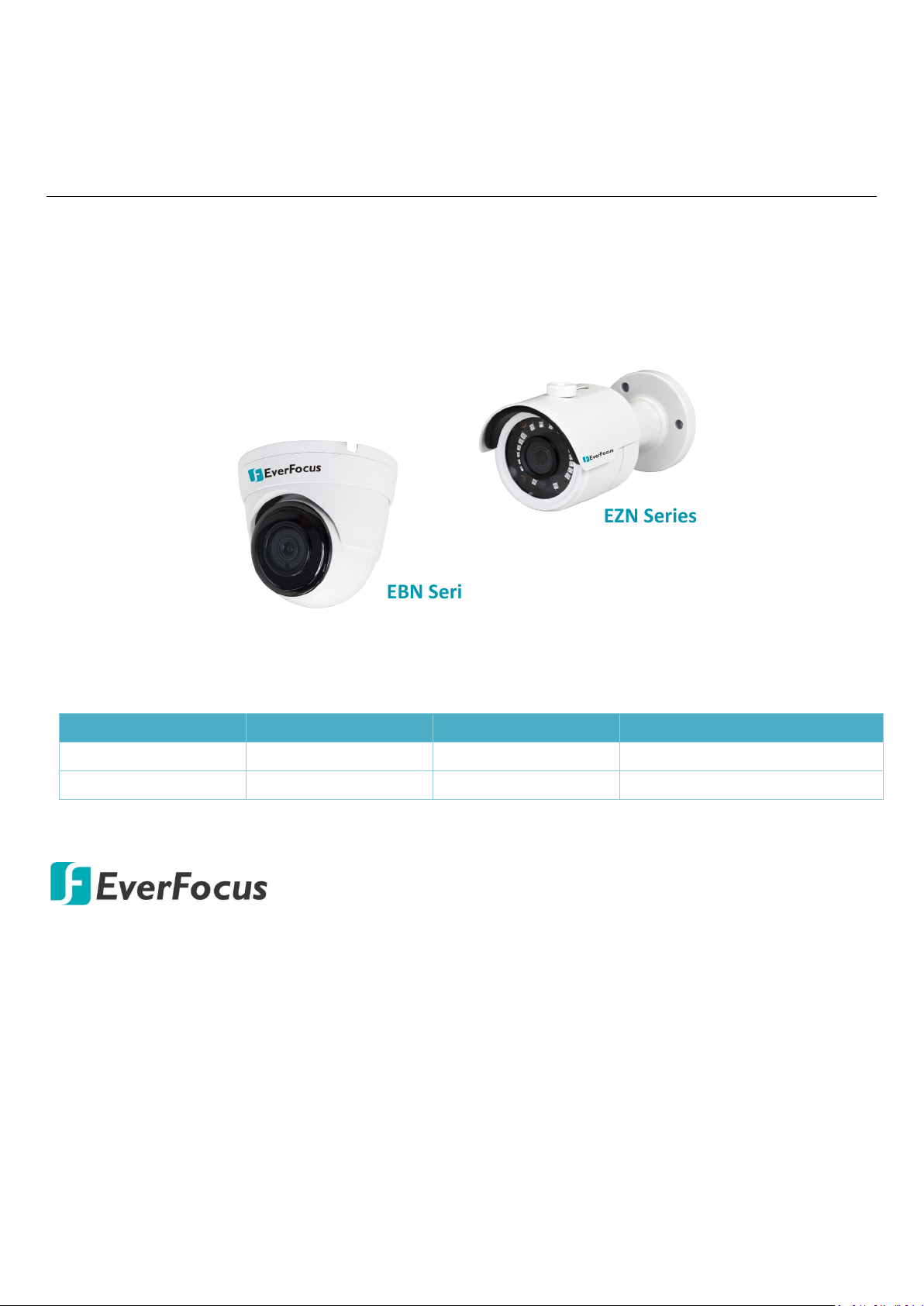
EBN Series
EZN Series
EBN Series
EBN1240-A
EBN1540-A
EBN1840-A / EBN1840-A15
Value IP Series Network Camera
Compact-Sized 2MP/5MP/8MP, H265, IR & WDR
Quick Installation Guide
This Quick Installation Guide can be applied to the following models:
Series 2MP 5MP 8MP
EZN Series EZN1240-A EZN1540-A EZN1840-A / EZN1840-A15
Copyright © EverFocus Electronics Corp.
Release Date: January, 2019
All the images including product pictures or screen shots in this document are for example only.
The images may vary depending on the product and software version. Information contained in
this document is subject to change without notice.
EverFocus Taiwan:
2F., No.12, Ln. 270, Sec. 3, Beishen Rd., Shenkeng Dist., New Taipei City 222, Taiwan
TEL: +886 2 2662 2338 FAX: +886 2 2662 3632 www.everfocus.com.tw
Page 2
90mm / 3.54"
Ø 100mm / 3.94"
75.47mm / 2.97"
75.9mm / 2.99"
154.52mm / 6.08"
Ø 71.81mm / 2.83"
LAN / PoE Cable
Power Cable (12VDC)
1. Introduction
The compact-sized Value IP series H.265 Outdoor IP camera provides
30fps at 2MP / 5MP / 8MP (4K) viewing resolution and H.265 or H.264
video compression formats. The models come with 3.6mm lens and
IP66 weather-proof housing. The Value IP series conforms to ONVIF for
compatibility with other network video devices.
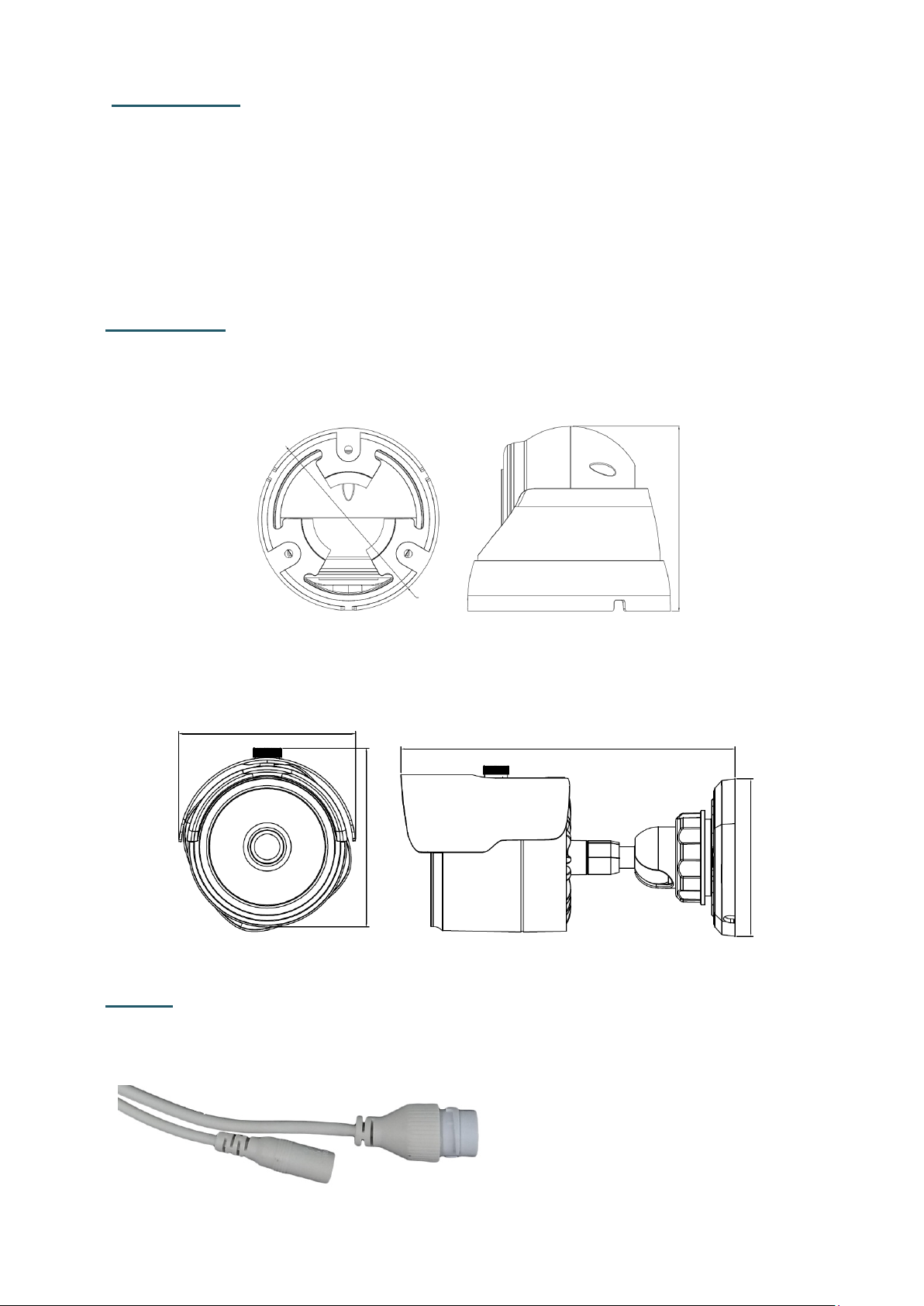
Dimensions
EBN Series
EZN Series
Cables
The cables provide connections for LAN/PoE and 12VDC power.
1
Page 3

2
2. Packing List
Please check that there is no missing item in the package before installing.
EBN Series EZN Series
1. Camera x 1
2. MAC Address Sticker x 2
3. Cable Gland Kit x 1
4. Screw & Anchor x 3
5. Mounting Sticker x 1
6. Quick Installation Guide x 1
7. Software CD x 1
1. Camera x 1
2. MAC Address Sticker x 2
3. Cable Gland Kit x 1
4. Screw & Anchor x 3
5. Hexagon Wrench x 1
6. Quick Installation Guide x 1
7. Software CD x 1
Note:
1. Equipment configurations and supplied accessories vary by country.
Please consult your local EverFocus office or agents for more
information. Please also keep the shipping carton for possible future
use.
2. Contact the shipper if any items appear to have been damaged in the
shipping process.
Optional Accessory
You can go to the product page on EverFocus’ website to check the related
optional accessories.
www.everfocus.com.tw
Page 4

3
Screw Position x 3
Optionally drill a Cable Hole if
you want to run the cables
through the surface.
Twist Outer Housing counterclockwise
Remove the Outer Housing
3. Installation
3.1 EBN Series
1. Stick the Mounting Sticker on the surface to mark the 3 screw positions.
Drill 3 screw-depth holes on the surface and then push the supplied 3
Screw Anchors into the holes. Optionally drill a Cable Hole on the center
if you want to run the cables through the surface.
2. Twist the Outer Housing counterclockwise and then remove the Outer
Housing.
3. Before screwing the Camera Base to the surface, thread the cables
either from the side-cut of the Camera Base or through the surface.
Page 5

4
Waterproof Ring Cable Gland
Stopper Screw Cap
RJ-45 Cable
LAN/PoE Cable
Screw Cap
Cable Gland
4. Screw the Camera Base to the surface using the supplied 3 Screws.
5. Place the camera body back to the Camera Base and twist back the
Outer Housing. Do not twist the Outer Housing too tight as you will
have to adjust camera angles while viewing camera live view.
6. Connect the camera to the network using the supplied Cable Gland Kit.
a. Insert a RJ-45 network cable (without the RJ-45 connector on the one
end) through the supplied Waterproof Ring, Cable Gland, Stopper
and Screw Cap accordingly.
b. Connect the RJ-45 cable to the LAN/PoE Cable of the camera.
c. Tightly screw the Cable Gland and Screw Cap to the Rugged RJ-45
Connector Cable.
d. Crimp the RJ-45 connector onto the RJ-45 network cable. Note that
the wires should be placed into the RJ-45 connector based on the
following order (from left to right).
Page 6

5
Orange with white stripe
Orange
Green with white stripe
Blue
Blue with white stripe
Green
Brown with white stripe
Brown
Screw Anchor
Screw
Surface
7. Connect the camera to power. You can either connect the camera to a
12VDC power source or to a PoE switch using the PoE cable.
8. Access the camera live view. See 4. Accessing the Camera.
9. Adjust camera angles and then tightly twist back the Outer Housing.
3.2 EZN Series
1. Drill three holes on the surface according to the Camera Base and then
push the supplied 3 Screw Anchors into the holes. Drill another hole in
the middle within the 3 screw holes if you wish to run the wires into the
surface.
2. Before screwing the Camera Base to the surface, thread the cables
either from the side-cut of the Camera Base or through the surface.
3. Screw the camera to the surface using the supplied 3 Screws.
4. Connect the camera to the network using the supplied Cable Gland Kit.
a. Insert a RJ-45 network cable (without the RJ-45 connector on the one
end) through the supplied Waterproof Ring, Cable Gland, Stopper
and Screw Cap accordingly.
Page 7

6
Waterproof Ring Cable Gland
Stopper
Screw Cap
RJ-45 Cable
LAN/PoE Cable
Screw Cap
Cable Gland
Orange with white stripe
Orange
Green with white stripe
Blue
Blue with white stripe
Green
Brown with white stripe
Brown
Tilt Screw
Pan Screw
Rotate Screws (both sides)
b. Connect the RJ-45 cable to the LAN/PoE Cable of the camera.
c. Tightly screw the Cable Gland and Screw Cap to the Rugged RJ-45
Connector Cable.
d. Crimp the RJ-45 connector onto the RJ-45 network cable. Note that
the wires should be placed into the RJ-45 connector based on the
following order (from left to right).
5. Connect the camera to power. You can either connect the camera to a
12VDC power source or to a PoE switch using the PoE cable.
6. Access the camera live view. See 4. Accessing the Camera.
7. Adjust the pan/tilt/rotate angles of the camera by loosen the
Pan/Tilt/Rotate screws using the supplied Hexagon Wrench.
Page 8

7
EZN1240-A EZN1240-A
4. Accessing the Camera
You can look up the IP address of the IP camera using the IP Utility (IPU)
program, which is included in the software CD.
The default IP mode of the IP camera is DHCP. However, if there is no
dynamic IP address assigned to the device, its IP will switch to
192.168.0.10
By default, the ID is admin and there is no password. Please input a
password for the first-time login.
P/N: 4605B124002001A
 Loading...