

Page 1
Evco S.p.A. • Code 104K261E00
EVK261 Digital thermostat for normal temperature refrigerated transport, with compressor or instrument working days counter function version 1.00
GB ENGLISH
1 GETTING STARTED
1.1 Important
Read these instructions carefully before installing and using the instru-
ment and follow all additional information for installation and electrical
connection; keep these instructions close to the instrument for future
consultations.
The instrument must be disposed according to the local
legislation about the collection for electrical and electronic
equipment.
1.2 Installing the instrument
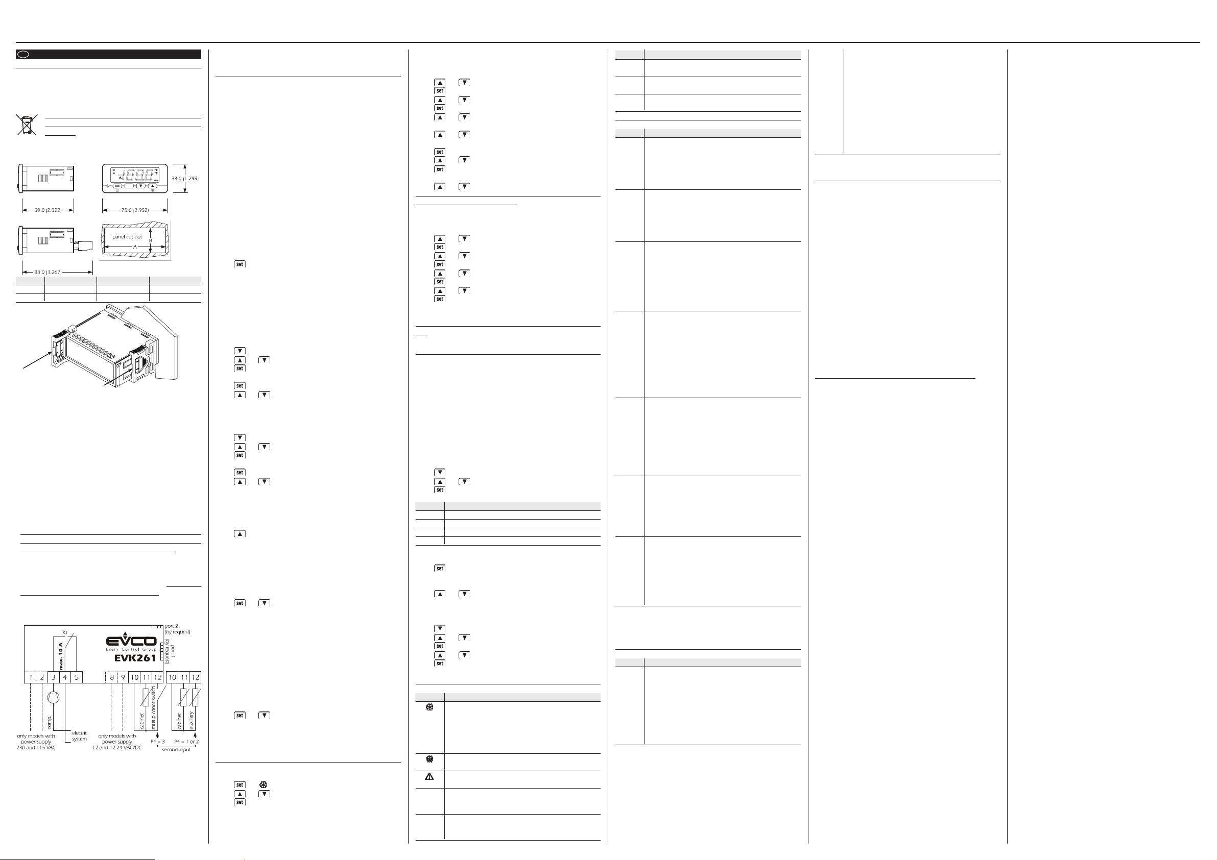
Panel mounting, with click brackets (supplied by the builder); dimen-
sions in mm (in).
DIMENS. MINIMUM TYPICAL MAXIMUM
A 71.0 (2.795) 71.0 (2.795) 71.8 (2.826)
B 29.0 (1.141) 29.0 (1.141) 29.8 (1.173)
Additional information for installation:
• 59.0 (2.322) is the maximum depth with screw terminal blocks
• 83.0 (3.267) is the maximum depth with extractable terminal blocks
• the panel thickness must not be higher than 8.0 mm (0.314 in)
• working conditions (working temperature, humidity, etc.) must be be-
tween the limits indicated in the technical data
• do not install the instrument close to heating sources (heaters, hot air
ducts, etc.), devices provided with big magnetos (big speakers, etc.),
locations subject to direct sunlight, rain, humidity, dust, mechanical
vibrations or bumps
• according to the safety legislation, the protection against electrical
parts must be ensured by a correct installation of the instrument; the
parts that ensure the protection must be installed so that you can not
remove them if not by using a tool.
1.3 Wiring diagram
With reference to the wiring diagrams:
• terminals 1 and 2 are available only in the models with power supply
230 VAC and 115 VAC; terminals 8 and 9 are available only in the
models with power supply 12 VAC/DC and 12-24 VAC/DC
• the function of the second input depends on parameter P4
• port 1 (by request) is the serial port for the communication with the
supervision system (through a serial interface, via TTL, with MODBUS
communication protocol) or with the programming key; the port must
not be used at the same time for the same purposes
• port 2 (by request) is the port for the communication with the remote
indicator; the indicator shows the quantity you have set with param-
eter P5.
Additional information for electrical connection:
• do not operate on the term. blocks with electrical or pneumatic screwers
• if the instrument has been moved from a cold location to a warm one,
the humidity could condense on the inside; wait about an hour be-
fore supplying it
• test the working power supply voltage, working electrical frequency
and working electrical power of the instrument; they must correspond
with the local power supply
• disconnect the local power supply before servicing the instrument
• do not use the instrument as safety device
• for repairs and information on the instrument please contact Evco
sales network.
2 USER INTERFACE
2.1 Preliminary information
There are the following operation status:
• status “on” (the instrument is supplied and is turned on: the regulators
can be turned on)
• status “stand-by” (the instrument is supplied but it is turned off via
software: the regulators are turned off)
• status “off” (the instrument is not supplied).
If parameter t0 has value 0, “turning on” means moving from status off
to status on; “turning off” means moving from status on to status off.
If parameter t0 has value 1, “turning on” means moving from status
stand-by to status on; “turning off” means moving from status on to
status stand-by.
After an interruption of power supply the instrument moves to the sta-
tus it was before the interruption.
2.2 Turning on/off the instrument if parameter t0 has
value 0
To turn on the instrument you have to supply it; to turn it off it is enough
to cut off the power supply.
2.3 Turning on/off the instrument if parameter t0 has
value 1
• make sure the keyboard is not locked and no procedure is running
• press 4 s.
2.4 The display
If the instrument is turned on, during the normal operation the display
will show the quantity you have set with parameter P5:
• if P5 = 0, the display will show the cabinet temperature
• if P5 = 1, the display will show the working setpoint
• if P5 = 2, the display will show the temperature read by the auxiliary
probe (only if parameter P4 has value 1 or 2).
2.5 Showing the cabinet temperature
• make sure the keyboard is not locked and no procedure is running
• press 2 s: the display will show the first available label
• press or to select “Pb1”
• press
To quit the procedure:
• press or do not operate 60 s
• press or as long as the display shows the quantity you have
set with parameter P5 or do not operate 60 s.
2.6 Showing the temperature read by the auxiliary probe
(only if parameter P4 has value 1 or 2)
• make sure the keyboard is not locked and no procedure is running
• press 2 s: the display will show the first available label
• press or to select “Pb2”
• press
To quit the procedure:
• press or do not operate 60 s
• press or as long as the display shows the quantity you have
set with parameter P5 or do not operate 60 s.
If the function of the second input is not the one of auxiliary probe
(parameter P4 = 0 or 3), the label “Pb2” will not be shown.
2.7 Activating the defrost by hand
• make sure the keyboard is not locked and no procedure is running
• press 4 s.
If the function of the second input is the one of evaporator probe (pa-
rameter P4 = 1) and to the defrost activation the evaporator tempera-
ture is above the one you have set with parameter d2, the defrost will
not be activated.
2.8 Locking/unlocking the keyboard
To lock the keyboard:
• make sure no procedure is running
• press and 2 s: the display will show “Loc” 1 s.
If the keyboard is locked, you will not be allowed to:
• turn on/off the instrument by hand
• show the temperature read by the auxiliary probe
• activate the defrost by hand
• modify the working setpoint with the procedure related in paragraph
3.1 (you also can modify the working setpoint through parameter SP)
• show the compressor working days
• erase the compressor working days
• show the instrument working days
• erase the instrument working days.
These operations provoke the visualization of the label “Loc” 1 s.
To unlock the keyboard:
• press and 2 s: the display will show “UnL” 1 s.
2.9 Silencing the buzzer
• make sure no procedure is running
• press a button (the first pressure of the button does not provoke its
usual effect).
3 SETTINGS
3.1 Setting the working setpoint
• make sure the keyboard is not locked and no procedure is running
• press LED will flash
• press or in 15 s; also look at parameters r1, r2 and r3
• press or do not operate 15 s.
You also can modify the working setpoint through parameter SP.
3.2 Setting configuration parameters
To gain access the procedure:
• make sure no procedure is running
• press and 4 s: the display will show “PA ”
• press
• press or in 15 s to set “-19”
• press or do not operate 15 s
• press and 4 s: the display will show “SP”.
To select a parameter:
• press or
To modify a parameter:
• press
• press or in 15
• press or do not operate 15 s.
To quit the procedure:
• press and 4 s or do not operate 60 s.
Switch off/on the power supply of the instrument after the
modification of the parameters.
3.3 Restoring the default value of configuration param-
eters
• make sure no procedure is running
• press and 4 s: the display will show “PA ”
• press
• press or in 15 s to set “743”
• press or do not operate 15 s
• press and 4 s: the display will show “dEF”
• press
• press or in 15 s to set “149”
• press or do not operate 15 s: the display will show “dEF” flash-
ing 4 s, after which the instrument will quit the procedure
• switch off/on the power supply of the instrument.
Make sure the default value of the parameters is appropri-
ate.
4 COMPRESSOR OR INSTRUMENT WORKING DAYS
COUNTING
4.1 Preliminary information
The instrument can store up to 1,999 compressor or instrument work-
ing days, after which the number 1,999 flashes.
If parameter t1 has value 0, the instrument will store the compressor
working days; if parameter t1 has value 1, the instrument will count its
working days (also when it is turned off via software).
When the number of working days gets the one you have set with
parameter t2, the display shows the label “SEr” flashing.
To freeze the signal “SEr” 1 h:
• press a button (the first pressure of the button does not provoke its
usual effect).
4.2 Showing the working days
• make sure the keyboard is not locked and no procedure is running
• press 2 s: the display will show the first available label
• press or to select “Ct”
• press the display will show in succession the following informa-
tion (for example):
INFOR. MEANING
dd the display is about to show the working days
26 the working days are 26 (to be continued ...)
hh the display is about to show the working hours
03 the working days are 26 and the hours are 3
Each information lasts 1 s.
To escape from the succession of information:
• press
To quit the procedure:
• escape from the succession of information
• press or as long as the display shows the quantity you have
set with parameter P5 or do not operate 60 s.
4.3 Erasing the working days
• make sure the keyboard is not locked and no procedure is running
• press 2 s: the display will show the first available label
• press or to select “rCt”
• press
• press or in 15 s to set “149”
• press or do not operate 15 s: the display will show “- - - -” flashing
4 s, after which the instrument will quit the procedure.
5 SIGNALS
5.1 Signals
LED MEANING
LED compressor
if it is lit, the compressor will be turned on
if it flashes:
• the modification of the working setpoint will be running
• a compressor protection will be running (parameters C0,
C1, C2 and i7)
LED defrost
if it is lit, the defrost will be running
LED alarm
if it is lit, an alarm will be running
°C LED Celsius degree
if it is lit, the unit of measure of the temperatures will be
Celsius degree (parameter P2)
°F LED Fahrenheit degree
if it is lit, the unit of measure of the temperatures will be
Fahrenheit degree (parameter P2)
CODE MEANING
SEr service of compressor or of instrument is requested (param-
eter t2); also look at chapter 4
Loc the keyboard and/or the working setpoint are locked (pa-
rameter r3); also look at paragraph 2.8
- - - - the quantity to show is not available (for example because
the probe is not enabled)
6 ALARMS
6.1 Alarms
CODE MEANING
AL Lower temperature alarm
Remedies:
• check the temperature joined to the alarm
• look at parameters A0, A1 and A2
Effects:
• no effect
AH Upper temperature alarm
Remedies:
• check the temperature joined to the alarm
• look at parameters A3, A4 and A5
Effects:
• no effect
id Door switch input alarm (only if parameter P4 has value 3
and parameter i0 has value 3)
Remedies:
• check the reasons that have provoked the activation of
the input
• look at parameters i0 and i1
Effects:
• the compressor will be turned off
iA Multipurpose input alarm (only if parameter P4 has value 3
and parameter i0 has value 0)
Remedies:
• check the reasons that have provoked the activation of
the input
• look at parameters i1 and i5
Effects:
• if parameter i5 has value 3, there will be no effect
• if parameter i5 has value 4, the compressor will be turned
off
iSd Instrument locked alarm (only if parameter P4 has value 3
and parameter i0 has value 0)
Remedies:
• check the reasons that have provoked the activation of
the multipurpose input
• switch off/on the power supply of the instrument
• look at parameters i1, i5, i7, i8 and i9
Effects:
• the regulators will be turned off
COH Overheated condenser alarm (only if parameter P4 has value
2)
Remedies:
• check the condenser temperature
• look at parameter C6
Effects:
• no effect
CSd Compressor locked alarm (only if parameter P4 has value 2)
Remedies:
• check the condenser temperature
• cut off the power supply of the instrument and clean the
condenser
• look at parameter C7
Effects:
• the compressor will be turned off
When the cause that has provoked the alarm disappears, the instru-
ment restores the normal operation, except for the instrument locked
alarm (code “iSd”) and the compressor locked alarm (code “CSd”) that
need you switch off/on the power supply of the instrument.
7 INTERNAL DIAGNOSTICS
7.1 Internal diagnostics
CODE MEANING
Pr1 Cabinet probe error
Remedies:
• look at parameter P0
• check the integrity of the probe
• check the connection instrument-probe
• check the cabinet temperature
Effects:
• the compressor activity will depend on parameters C4 and
C5
Pr2 Auxiliary probe error (only if parameter P4 has value 1 or 2)
Remedies:
• the same you saw in the previous case but related to the
auxiliary probe
Effects:
• if parameter P4 has value 1, the defrost will last the time
you will have set with parameter d3
• if parameter P4 has value 1 and parameter d8 has value 2,
the instrument will work as if parameter d8 had value 0
• if parameter P4 has value 2, the overheated condenser
alarm (code “COH”) and the compressor locked alarm
(code “CSd”) will never be activated
When the cause that has provoked the alarm disappears, the instru-
ment restores the normal operation.
8 TECHNICAL DATA
8.1 Technical data
Box: self-extinguishing grey.
Frontal protection: IP 65.
Connections: screw terminal blocks (power supply, inputs and out-
put), 6 poles connector (serial port; by request), 4 poles connector (to
the remote indicator; by request); extractable terminal blocks (power
supply, inputs and output) by request.
Working temperature: from 0 to 55 °C (32 to 131 °F, 10 ... 90% of
relative humidity without condensate).
Power supply: 230 VAC, 50/60 Hz, 3 VA (approximate); 115 VAC or
12-24 VAC/DC or 12 VAC/DC by request.
Alarm buzzer: by request.
Measure inputs: 1 (cabinet probe) for PTC/NTC probes.
Digital inputs: 1 (multipurpose/door switch) for NO/NC contact (free
of voltage, 5 V 1 mA) also configurable for measure input (evaporator
or condenser probe, for PTC/NTC probes).
Working range: from -50.0 to 150.0 °C (-50 to 300 °F) for PTC probe,
from -40.0 to 105.0 °C (-40 to 220 °F) for NTC probe.
Resolution: 0.1 °C/1 °C/1 °F.
Digital outputs:1 relay:
• compressor relay: 16 res. A @ 250 VAC (change-
over contact).
The maximum current allowed on the load is 10 A.
Serial port: port for the communication with the supervision system
(through a serial interface, via TTL, with MODBUS communication pro-
tocol) or with the programming key; by request.
Further communication ports: port for the communication with
the remote indicator; by request.
Page 2
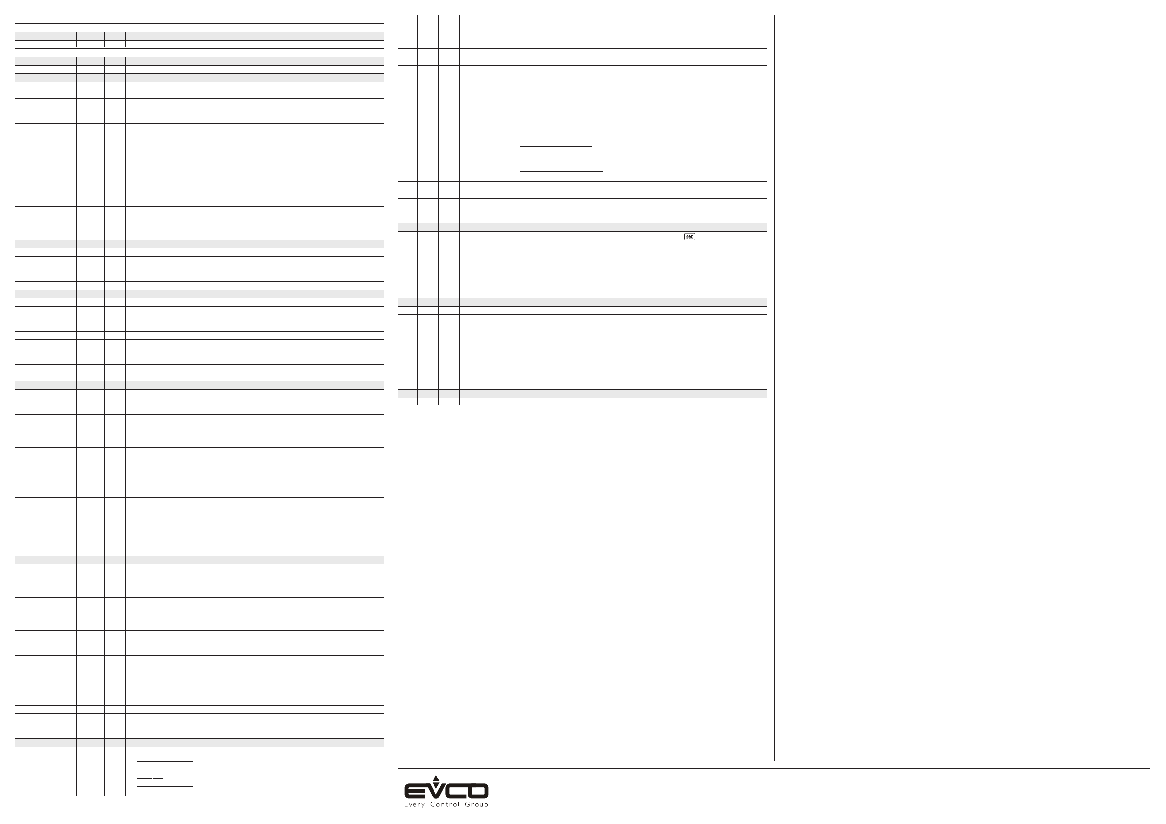
9 WORKING SETPOINTS AND CONFIGURATION PARAMETERS
9.1 Working setpoints
MIN. MAX. U.M. DEF. WORKING SETPOINTS
r1 r2 °C/°F (1) 0.0 working setpoint
9.2 Configuration parameters
PARAM. MIN. MAX. U.M. DEF. WORKING SETPOINTS
SP r1 r2 °C/°F (1) 0.0 working setpoint
PARAM. MIN. MAX. U.M. DEF. MEASURE INPUTS
CA1 -25.0 25.0 °C/°F (1) 0.0 cabinet probe offset
CA2 -25.0 25.0 °C/°F (1) 0.0 auxiliary probe offset (only if P4 = 1 or 2)
P0 0 1 - - - 1 kind of probe
0 = PTC
1 = NTC
P1 0 1 - - - 1 decimal point Celsius degree (for the quantity to show during the normal operation)
1 = YES
P2 0 1 - - - 0 unit of measure temperature (2)
0=°C
1=°F
P4 0 3 - - - 3 second input function
0 = input not enabled
1 = measure input (evaporator probe)
2 = measure input (condenser probe)
3 = digital input (multipurpose/door switch input)
P5 0 2 - - - 0 quantity to show during the normal operation
0 = cabinet temperature
1 = working setpoint
2 = temperature read by the auxiliary probe (only if P4 = 1 or 2)
PARAM. MIN. MAX. U.M. DEF. MAIN REGULATOR
r0 0.1 15.0 °C/°F (1) 2.0 working setpoint differential
r1 -99.0 r2 °C/°F (1) -50.0 minimum working setpoint
r2 r1 99.0 °C/°F (1) 50.0 maximum working setpoint
r3 0 1 - - - 0 locking the working setpoint modification (with the procedure related in paragraph 3.1; 1 = YES)
r4 0.0 99.0 °C/°F (1) 0.0 temperature increase during function Energy Saving (only if P4 = 3 and i0 = 0); also look at i5
PARAM. MIN. MAX. U.M. DEF. COMPRESSOR PROTECTIONS
C0 0 240 min 0 compressor delay since you turn on the instrument
C1 0 240 min 5 minimum time between two activations in succession of the compressor; also compressor delay since
the end of the cabinet probe error (3)
C2 0 240 min 3 minimum time the compressor remains turned off
C3 0 240 s 0 minimum time the compressor remains turned on
C4 0 240 min 10 time the compressor remains turned off during the cabinet probe error; also look at C5
C5 0 240 min 10 time the compressor remains turned on during the cabinet probe error; also look at C4
C6 0.0 199.0 °C/°F (1) 80.0 condenser temperature above which the overheated condenser alarm is activated (only if P4 = 2) (4)
C7 0.0 199.0 °C/°F (1) 90.0 condenser temperature above which the compressor locked alarm is activated (only if P4 = 2)
C8 0 15 min 1 compressor locked alarm delay (only if P4 = 2) (5)
PARAM. MIN. MAX. U.M. DEF. DEFROST
d0 0 99 h 8 defrost interval; also look at d8 (6)
0 = the defrost at intervals will never be activated
d2 -99.0 99.0 °C/°F (1) 2.0 defrost cutoff temperature (only if P4 = 1)
d3 0 99 min 30 defrost duration if P4 = 0, 2 or 3; defrost maximum duration if P4 = 1
0 = the defrost will never be activated
d4 0 1 - - - 0 defrost when you turn on the instrument
1 = YES
d5 0 99 min 0 defrost delay when you turn on the instrument (only if d4 = 1); also look at i5
d6 0 1 - - - 1 temperature shown during the defrost
0 = cabinet temperature
1 = if to the defrost activation the cabinet temperature is below “working setpoint + r0”, at most “work-
ing setpoint + r0”; if to the defrost activation the cabinet temperature is above “working setpoint +
r0”, at most the cabinet temperature to the defrost activation (7)
d8 0 2 - - - 0 kind of defrost interval
0 = the defrost will be activated when the instrument will have remained turned on the time d0
1 = the defrost will be activated when the compressor will have remained turned on the time d0
2 = the defrost will be activated when the evaporator temperature will have remained below the tem-
perature d9 the time d0 (only if P4 = 1) (8)
d9 -99.0 99.0 °C/°F (1) 0.0 evaporator temperature above which the count of the defrost interval is suspended (only if P4 = 1 and
d8 = 2)
PARAM. MIN. MAX. U.M. DEF. TEMPERATURE ALARMS
A0 0 1 - - - 0 temperature joined to the lower temperature alarm
0 = cabinet temperature
1 = temperature read by the auxiliary probe (only if P4 = 1 or 2) (9)
A1 -99.0 99.0 °C/°F (1) -10.0 temperature below which the lower temperature alarm is activated; also look at A0 and A2 (4)
A2 0 2 - - - 1 kind of lower temperature alarm
0 = alarm not enabled
1 = relative to the working setpoint (or "working setpoint - A1”; consider A1 without sign)
2 = absolute (or A1)
A3 0 1 - - - 0 temperature joined to the upper temperature alarm
0 = cabinet temperature
1 = temperature read by the auxiliary probe (only if P4 = 1 or 2) (9)
A4 -99.0 99.0 °C/°F (1) 10.0 temperature above which the upper temperature alarm is activated; also look at A3 and A5 (4)
A5 0 2 - - - 1 kind of upper temperature alarm
0 = alarm not enabled
1 = relative to the working setpoint (or "working setpoint + A4”; consider A4 without sign)
2 = absolute (or A4)
A6 0 240 min 120 upper temperature alarm delay since you turn on the instrument (only if A3 = 0)
A7 0 240 min 15 temperature alarm delay
A8 0 240 min 15 upper temperature alarm delay since the end of the defrost (only if A3 = 0) (10)
A9 0 240 min 15 upper temperature alarm delay since the deactivation of the door switch input (only if P4 = 3 and
i0 = 3) (11)
PARAM. MIN. MAX. U.M. DEF. DIGITAL INPUTS (only if P4 = 3)
i0 0 3 - - - 3 kind of digital input
0=MULTIPURPOSE INPUT - in this case look at parameters i1, i5, i7, i8 and i9
1=RESERVED
2=RESERVED
3=DOOR SWITCH INPUT - in this case look at parameters i1, i2 and i3; the activation of the input will
turn off the compressor (at most the time i3 or as long as the input will be deactivated) (12)
i1 0 2 - - - 0 kind of contact digital input
0 = NO (input active if you close the contact)
1 = NC (input active if you open the contact)
2 = input not enabled
i2 -1 120 min 30 delay to signal the door switch input alarm
-1 = no signal
i3 -1 120 min 15 maximum duration of the effect provoked by the activat. of the door switch input (-1 = the effect will last
as long as the input will be deactivated)
i5 0 5 - - - 3 effect provoked by the activation of the multipurpose input
0 = no effect
1=SYNCHRONIZING THE DEFROSTS - spent the time d5 the defrost will be activated (13)
2=ACTIVATING THE ENERGY SAVING - function Energy Saving will be activated (as long as the input
will be deactivated); also look at r4 (13)
3=ACTIVATING THE EXTERNAL ALARM - spent the time i7 the display will show the code “iA” flashing
and the buzzer will be activated (as long as the input will be deactivated)
4=ACTIVATING THE MANOSTAT - the compressor will be turned off, the display will show the code “iA”
flashing and the buzzer will be activated (as long as the input will be deactivated); also look at i7, i8
and i9
5=TURNING OFF THE INSTRUMENT - the instrum. will be turned off via software (as long as the input
will be deact.); also look at C0, d4 and A6
i7 0 120 min 0 if i5 = 3, delay to signal the multipurpose input alarm
if i5 = 4, compressor delay since the deactivation of the multipurpose input (14)
i8 0 15 - - - 0 number of multipurpose input alarms such as to provoke the instrument locked alarm (only if i5 = 4)
0 = alarm not enabled
i9 1 999 min 240 time without multipurpose input alarms in order that the alarm counter is cleared (only if i5 = 4)
PARAM. MIN. MAX. U.M. DEF. VARIOUS
t0 0 1 - - - 0 turning on/off the instrument (via software) by hand through button
1 = YES
t1 0 1 - - - 0 kind of data to be counted (15)
0 = compressor working days
1 = instrument working days (16)
t2 0 1,999 d 100 if t1 = 0, number of compressor working days above which service is requested
if t1 = 1, number of instrument working days above which service is requested
0 = function not enabled
PARAM. MIN. MAX. U.M. DEF. SERIAL NETWORK (MODBUS)
LA 1 247 - - - 247 instrument address
Lb 0 3 - - - 2 baud rate
0 = 2,400 baud
1 = 4,800 baud
2 = 9,600 baud
3 = 19,200 baud
LP 0 2 - - - 2 parity
0 = none
1 = odd
2 = even
PARAM. MIN. MAX. U.M. DEF. RESERVED
E9 0 1 - - - 1 reserved
(1) the unit of measure depends on parameter P2
(2) set the parameters related to the regulators appropriately after the modification of the parameter P2
(3) if parameter C1 has value 0, the delay since the end of the cabinet probe error will however be 2 min
(4) the differential of the parameter is 2.0 °C/4 °F
(5) if (when you turn on the instrument) the condenser temperature is above the one you have set with parameter C7, parameter C8 will have
no effect
(6) the instrument stores the count of the defrost interval every 30 min; the modification of parameter d0 has effect since the end of the previous
defrost interval or since the activation of a defrost by hand
(7) the display restores the normal operation as soon as the defrost ends and the cabinet temperature falls below the one that has locked the
display (or if a temperature alarm arises)
(8) if parameter P4 has value 0, 2 or 3, the instrument will work as if parameter d8 had value 0
(9) if parameter P4 has value 0 or 3, the instrument will work as if parameter had value 0
(10) during the defrost the temperature alarms are not enabled, on condition that they have arisen after the activation of the defrost
(11) during the activation of the door switch input the upper temperature alarm is not enabled, on condition that it has arisen after the activation
of the input
(12) the compressor is turned off spent 10 s since the activation of the input
(13) the effect is not signalled
(14) make sure the time you have set with parameter i7 is shorter than the one you have set with parameter i9
(15) erase the working days after the modification of parameter t1
(16) the instrument counts the working days also when it is turned off via software.
EVCO S.p.A. This document belongs to Evco; unless you are authorized by Evco, you can not publish it.
Via Mezzaterra 6, 32036 Sedico Belluno ITALY Evco does not take any responsibility about features, technical data and possible mistakes related in this document or coming by its use.
Phone +39-0437-852468 • Fax +39-0437-83648 Evco does not take any responsibility about damages coming by the non-observance of the additional information.
PT • 22/10
[email protected] • www.evco.it Evco reserves the right to make any change without prior notice and at any time without prejudice the basic safety and operating features.
 Loading...