

Page 1
EVCO S.p.A. EVFTFT818 | Installer manual ver. 2.1 | Code 144FTFT818E214
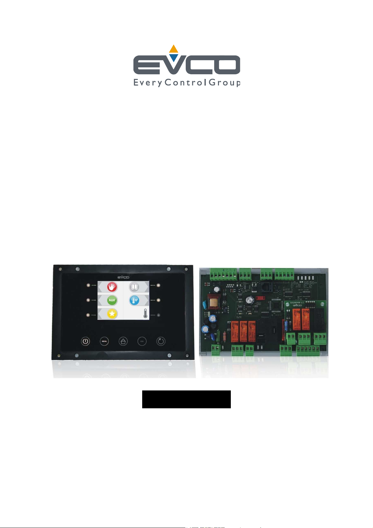
EVFTFT818
Controller in split execution for
temperature-controlled blast chillers with
capacitive touch-key user interface, which
can be integrated into the unit
ENGLISH
INSTALLER MANUAL ver. 2.1
CODE 144FTFT818E214
page 1 of 94
Page 2

EVCO S.p.A. EVFTFT818 | Installer manual ver. 2.1 | Code 144FTFT818E214
Important
Important
Read this document thoroughly before installation and before use of the device and follow all recommendations; keep
this document with the device for future consultation.
The following symbols support reading of the document:
indicates a suggestion
indicates a warning.
The device must be disposed of in compliance with local Standards regarding the collection of electric and electronic
equipment.
page 2 of 94
Page 3

EVCO S.p.A. EVFTFT818 | Installer manual ver. 2.1 | Code 144FTFT818E214
Index
1
INTRODUCTION ................................................................................................................................... 6
1.1 Introduction ........................................................................................................................................ 6
1.2 Summary table of the main features and the models available ................................................................... 7
2
DESCRIPTION .................................................................................................................................... 10
2.1 Description of the user interface .......................................................................................................... 10
2.2 Description of the control module ......................................................................................................... 12
3
DIMENSIONS AND INSTALLATION ........................................................................................................ 14
3.1 User interface dimensions ................................................................................................................... 14
3.2 Control module dimensions ................................................................................................................. 14
3.3 User interface installation .................................................................................................................... 15
3.4 Control module installation .................................................................................................................. 15
3.5 Installation warnings .......................................................................................................................... 15
4
ELECTRIC CONNECTION ...................................................................................................................... 16
4.1 Electric connection ............................................................................................................................. 16
4.1.1 Insertion of the user interface-control module terminating resistor ................................................... 17
4.1.2 Insertion of the RS-485 serial port terminating resistor ................................................................... 18
4.2 Warnings for the electric connection ..................................................................................................... 18
5
USER INTERFACE ............................................................................................................................... 19
5.1 Foreword .......................................................................................................................................... 19
5.2 Device commissioning ........................................................................................................................ 19
5.3 Switching the device on/off ................................................................................................................. 20
5.4 The display ........................................................................................................................................ 20
5.5 Display of inputs and outputs status ..................................................................................................... 22
5.6 Defrosting activation in manual mode ................................................................................................... 22
5.7 Locking/unlocking of the keyboard ....................................................................................................... 23
Silencing the buzzer .................................................................................................................................... 24
6
OPERATION ....................................................................................................................................... 25
6.1 Foreword .......................................................................................................................................... 25
6.1.1 Foreword regarding needle probe ................................................................................................. 25
6.2 Temperature-controlled blast chilling and storage .................................................................................. 26
6.3 Temperature-controlled hard blast chilling and storage ............................................................................... 27
6.4 Time-controlled blast chilling and storage .............................................................................................. 29
6.5 Time-controlled hard blast chilling and storage ...................................................................................... 31
6.6 Continuous blast chilling ..................................................................................................................... 33
6.7 Temperature-controlled deep freezing and storage ................................................................................. 33
6.8 Temperature-controlled soft deep freezing and storage ........................................................................... 35
6.9 Time-controlled deep freezing and storage ............................................................................................ 37
6.10 Time-controlled soft deep freezing and storage .................................................................................. 39
6.11 Continuous deep freezing ................................................................................................................ 41
6.12 Blast chilling/deep freezing intensity ................................................................................................. 41
6.12.1 Selecting the evaporator fan speed ............................................................................................... 43
6.13 Pre-cooling start-up ........................................................................................................................ 43
6.14 Management of the test regarding correct insertion of the needle probe ................................................ 44
6.15 Switching on UV light for sterilisation cycle ........................................................................................ 44
6.16 Heating the needle probe ................................................................................................................ 45
6.17 Fish sanification ............................................................................................................................. 45
7
“PROGRAMS” FUNCTION ..................................................................................................................... 47
page 3 of 94
Page 4

EVCO S.p.A. EVFTFT818 | Installer manual ver. 2.1 | Code 144FTFT818E214
7.1
Foreword .......................................................................................................................................... 47
7.2 Memorisation of a program ................................................................................................................. 47
7.3 Execution of a program ....................................................................................................................... 48
8
“FAVOURITES” FUNCTION ................................................................................................................... 49
8.1 Foreword .......................................................................................................................................... 49
8.2 Execution of a program ....................................................................................................................... 49
9
“HACCP” FUNCTION............................................................................................................................ 50
9.1 Foreword .......................................................................................................................................... 50
9.2 Display of information relative to the HACCP alarms ............................................................................... 50
9.3 Deleting the information relative to the HACCP alarms ............................................................................ 51
10
COMPRESSOR OPERATING HOURS COUNT ............................................................................................ 53
10.1 Display of compressor operating hours .............................................................................................. 53
11
CONFIGURATION ............................................................................................................................... 54
11.1 Setting the real date and time ......................................................................................................... 54
11.2 Setting the configuration parameters ................................................................................................ 54
11.3 Restoring the factory settings .......................................................................................................... 55
11.3.1 Access to the procedure .............................................................................................................. 55
11.3.2 Restoring the configuration parameters ......................................................................................... 56
11.3.3 Deleting programs ...................................................................................................................... 56
11.3.4 Deleting favourites ..................................................................................................................... 57
11.3.5 Deleting the compressor operating hours....................................................................................... 57
11.4 List of configuration parameters ....................................................................................................... 58
12
USE OF THE USB PORT (ONLY AVAILABLE IN THE MODEL EVFTFT818P7U) ................................................ 71
12.1 Foreword ....................................................................................................................................... 71
12.2 Upload and download of the configuration parameters ........................................................................ 71
12.3 Upload and download of the programs .............................................................................................. 72
12.4 Download of the information relative to the HACCP alarms .................................................................. 74
13
SIGNALS AND INDICATIONS ............................................................................................................... 76
13.1 Signals.......................................................................................................................................... 76
13.2 Indications .................................................................................................................................... 78
14
ALARMS ............................................................................................................................................ 79
14.1 Alarms .......................................................................................................................................... 79
15
ERRORS ............................................................................................................................................ 81
15.1 Errors ........................................................................................................................................... 81
16
ACCESSORIES ................................................................................................................................... 83
16.1 Data recording device EVUSBREC01 ................................................................................................. 83
16.1.1 Introduction ............................................................................................................................... 83
16.1.2 Description ................................................................................................................................ 83
16.1.3 Dimensions ................................................................................................................................ 83
16.1.4 Connection to the device ............................................................................................................. 84
16.2 Optoisolated RS-485/RS-232 serial interface EVIF21RS7I .................................................................... 84
16.2.1 Introduction ............................................................................................................................... 84
16.2.2 Description ................................................................................................................................ 84
16.2.3 Dimensions ................................................................................................................................ 85
16.2.4 Connection to the device ............................................................................................................. 85
16.3 Phase cut speed regulator for single phase fans EVDFAN1 ................................................................... 86
16.3.1 Introduction ............................................................................................................................... 86
16.3.2 Description ................................................................................................................................ 86
16.3.3 Dimensions ................................................................................................................................ 87
page 4 of 94
Page 5

EVCO S.p.A. EVFTFT818 | Installer manual ver. 2.1 | Code 144FTFT818E214
16.3.4
Connection to the device ............................................................................................................. 87
17
TECHNICAL DATA ............................................................................................................................... 88
17.1 Technical data ............................................................................................................................... 88
page 5 of 94
Page 6

EVCO S.p.A. EVFTFT818 | Installer manual ver. 2.1 | Code 144FTFT818E214
1 INTRODUCTION
1.1 Introduction
EVFTFT818 is a digital controller studied to manage temperature-controlled blast chillers, which can be mechanically
and aesthetically integrated into the unit.
The controller is fitted with:
- clock
- signal buzzer and alarm
- 6 analogue inputs (cabinet probe, “multipoint” needle probe with up to three sensors, evaporator probe and
condenser probe) for PTC/NTC probes
- 4 digital inputs (door micro switch, high pressure, low pressure and compressor circuit breaker protection)
- 1 PWM analogue output for management of the evaporator fan
- 8 digital outputs (electromechanical relays), 1 x 16 A res. @ 250 VAC for compressor management, 1 x 16 A
res. @ 250 VAC for management of needle probe heating, 6 x 8 A res. @ 250 VAC for management of
defrosting, evaporator fan, condenser fan, door heating elements, of a seventh utility that can be set for the
cabinet light or UV light and an eighth utility that can be configured for pump down valve or alarm output.
- RS-48 serial port with MODBUS communication protocol
- USB port (according to the model).
The device can manage both temperature-controlled and timed and hard and soft blast chilling and storage cycles and
deep freezing and storage cycles, with intensity management via the use of a PWM analogue output and phase cut
speed regulator for EVDFAN1 single phase fans.
Every operating cycle can be preceded by pre-cooling. The temperature-controlled cycles are also preceded by a test
for checking the correct connection of the needle probe, with "multipoint" probes management (up to three sensors).
The device is available in “split” execution (user interface + control module).
The user interface is behind a Plexiglas sheet and is made up from a 320 x 240 pixel colour TFT graphic display (3.5")
and 11 capacitive touch-keys; installation is envisioned on rear of panel with studs.
The control module is without cover and installation is envisioned on flat surface with spacers.
The "programs" function can be used to memorise some settings in a program and start an operating cycle with the
settings it has memorised.
Via the "HACCP" function, up to 9 events can be memorised for each of the 3 HACCP alarms (temperature-controlled
blast chilling or deep freezing not concluded within the maximum duration alarm, maximum temperature during
storage alarm and power cut during storage alarm); the critical value, date and time at which the alarm occurred and
the duration can be memorised for each HACCP alarm.
It is possible to connect the controller to the Parameters Manager set-up software system, to the monitoring and
surveillance system of the RICS plants, to the data recording device and to download the recorded data (via USB)
EVUSBREC01.
Some of them have an USB communication port; through this port it is possible to make the upload and the download
of the configuration parameters and of the programs and make the download of the information relative to the HACCP
alarms.
The following are indicated among the many other features:
- IP65 protection rating of the user interface
- memorisation of the defrosting interval
- management of temperature alarms
- compressor operating hours count
- "keyboard lock" function.
page 6 of 94
Page 7
EVCO S.p.A. EVFTFT818 | Installer manual ver. 2.1 | Code 144FTFT818E214
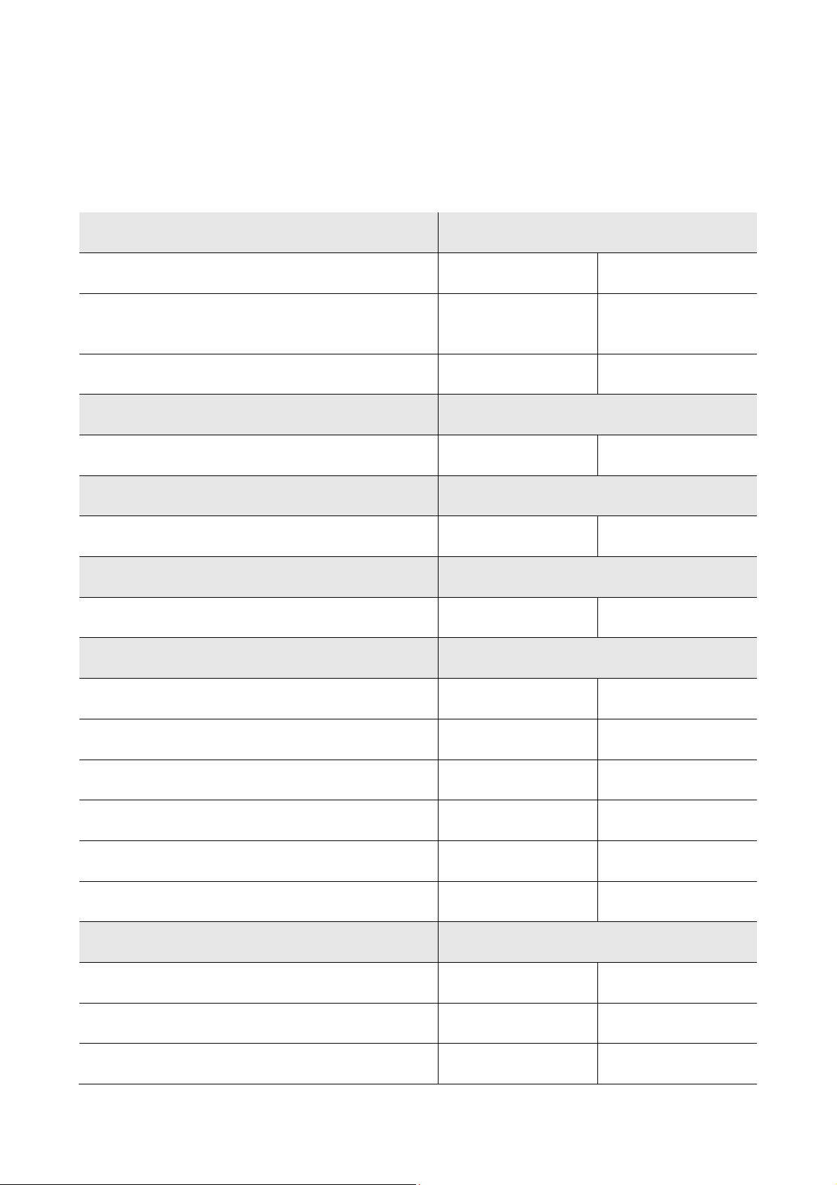
1.2 Summary table of the main features and the models
available
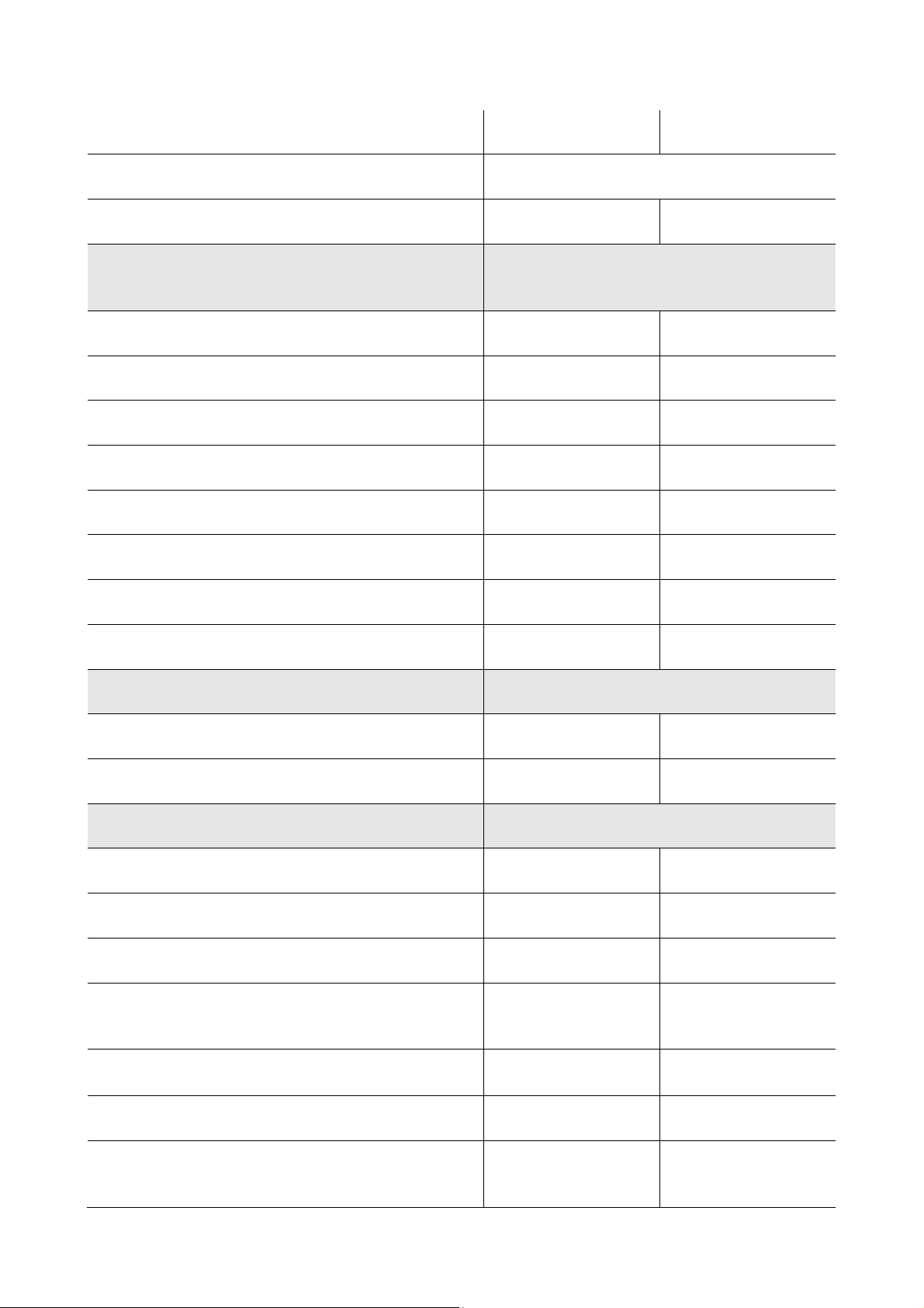
The following table illustrates the main features of the device and the models available.
“ / “ indicates the feature can be set via a configuration parameter.
User interface (without cover) EVFTFT818
200.0 x 135.0 mm (7.874 x 13.498 cm; L x H) • •
320 x 240 pixel
(3.5 inch) colour TFT graphics display
number of keys (capacitive touch-key type) 11 11
Control module (without cover) EVFTFT818
166.0 x 116.0 mm (6.535 x 11.598 cm; L x H) • •
Connections EVFTFT818
removable screw terminal board • •
Power supply EVFTFT818
230 VAC • •
Analogue inputs EVFTFT818
cabinet probe PTC/NTC PTC/NTC
• •
needle probe 1 PTC/NTC PTC/NTC
needle probe 2 PTC/NTC PTC/NTC
needle probe 3 PTC/NTC PTC/NTC
evaporator probe PTC/NTC PTC/NTC
condenser probe PTC/NTC PTC/NTC
Digital inputs (for NO/NC contact) EVFTFT818
door micro switch • •
high pressure • •
low pressure • •
page 7 of 94
Page 8
EVCO S.p.A. EVFTFT818 | Installer manual ver. 2.1 | Code 144FTFT818E214
compressor circuit breaker protection • •
Analogue outputs (PWM) EVFTFT818
evaporator fan (1) (1)
Digital outputs (electromechanical relays; A res. @
250 VAC)
EVFTFT818
compressor 16 A 16 A
defrosting 8 A 8 A
evaporator fan (1) (1)
condenser fan 8 A 8 A
door heating elements 8 A 8 A
needle probe heating 16 A 16 A
cabinet light/UV light 8 A 8 A
pump down valve/alarm 8 A 8 A
Communication port EVFTFT818
RS-485 serial port with MODBUS communication protocol • •
USB serial port •
Other features EVFTFT818
IP65 protection rating of the user interface IP65 IP65
clock • •
signal buzzer and alarm • •
management of blast chilling and storage/deep freezing and
storage cycles
management of temperature/time controlled operation
cycles
• •
• •
hard/soft operating cycles management • •
management of the test regarding correct insertion of the
needle probe
• •
page 8 of 94
Page 9

EVCO S.p.A. EVFTFT818 | Installer manual ver. 2.1 | Code 144FTFT818E214
memorisation of the defrosting interval • •
management of temperature alarms • •
compressor operating hours count • •
“programs” function • •
“HACCP” function • •
"keyboard lock" function • •
configuration parameters access password • •
restoring the factory settings • •
Codes EVFTFT818
codes EVFTFT818P7 EVFTFT818P7U
Notes:
(1) The evaporator fan control signal can be analogue or digital.
For further information, see chapter 15 "TECHNICAL DATA"; for other models contact the EVCO sales network.
page 9 of 94
Page 10
EVCO S.p.A. EVFTFT818 | Installer manual ver. 2.1 | Code 144FTFT818E214
2 DESCRIPTION
2.1 Description of the user interface
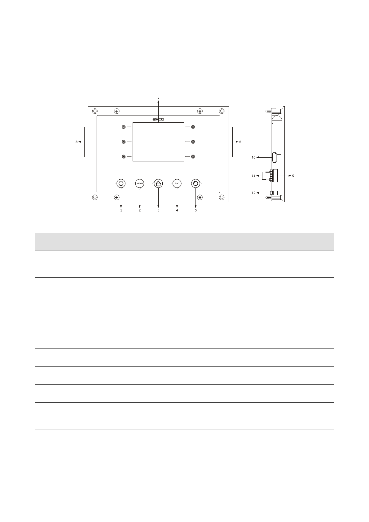
The following drawing illustrates the aspect of the EVFTFT818 user interface.
The following table illustrates the meaning of EVFTFT818 user interface parts.
Part Meaning
1
2 options key, hereon call "MENU key"
3 pre-selection key, hereon call "HOME key"
4 annul key, hereon call "ESCAPE key"
5 cycle start/cycle cut-off key, hereon called "START/STOP key"
6 interactive keys
7 display
on/off key, herein called also "ON/STAND-BY key"
8 interactive keys
9
10 USB serial port (only available in the model EVFTFT818P7U)
11
RS-485 serial port with MODBUS communication protocol and communication port with control
module (signal and power supply)
jumper for the insertion of the terminating resistor of the user interface-control module
communication port and of the RS-485 serial port
page 10 of 94
Page 11

EVCO S.p.A. EVFTFT818 | Installer manual ver. 2.1 | Code 144FTFT818E214
12 grounding
For further information, see the next chapters.
page 11 of 94
Page 12
EVCO S.p.A. EVFTFT818 | Installer manual ver. 2.1 | Code 144FTFT818E214
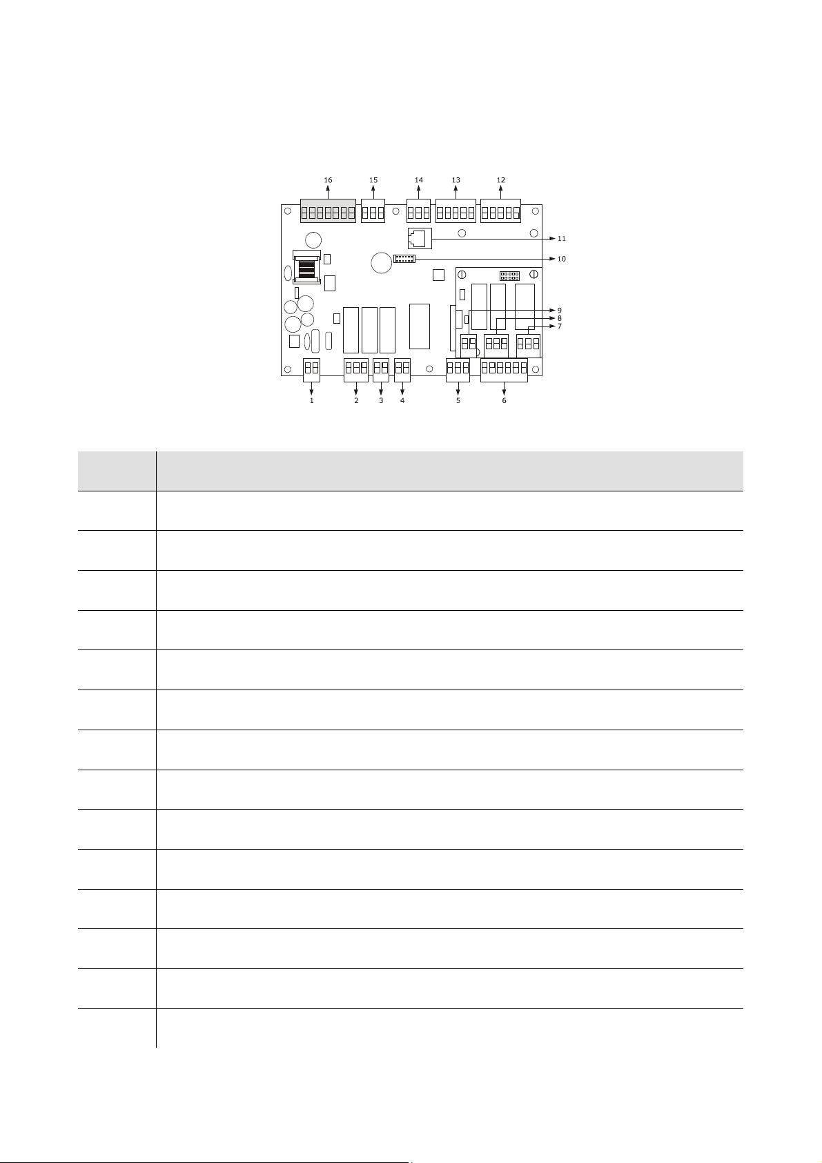
2.2 Description of the control module
The following drawing illustrates the aspect of the EVFTFT818 control module.
The following table illustrates the meaning of EVFTFT818 control module parts.
Part Meaning
1 power supply
2 digital outputs K3 and K4
3 digital output K2
4 digital output K1
5 digital output K5
6 digital inputs
7 digital output K6
8 digital outputs K7 and K8
9 reserved
10 reserved
11 reserved
12 analog inputs (cabinet probe, evaporator probe and condenser probe)
13 analog inputs (needle probe 1, needle probe 2 and needle probe 3)
14 reserved
page 12 of 94
Page 13

EVCO S.p.A. EVFTFT818 | Installer manual ver. 2.1 | Code 144FTFT818E214
15 PWM analogue output
16 communication port with the user interface (signal and power supply)
For further information, see the next chapters.
page 13 of 94
Page 14
EVCO S.p.A. EVFTFT818 | Installer manual ver. 2.1 | Code 144FTFT818E214
partic. A
partic. A
partic. A
partic. A
175,0 (6,889)
180,0 (7,086)
200,0 (7,874)
1
1
0
,
0
(
4
,
3
3
0
)
1
2
2
,
0
(
4
,
8
0
3
)
1
3
5
,
0
(
5
,
3
1
4
)
R
2
,
0
(
0
,
0
7
8
)
1
1
6
,
0
(
4
,
5
6
6
)
1
0
8
,
0
(
4
,
2
5
1
)
1
0
0
,
0
(
3
,
9
3
7
)
8
6
,
0
(
3
,
3
8
5
)
Ø 4,0 (0,157)
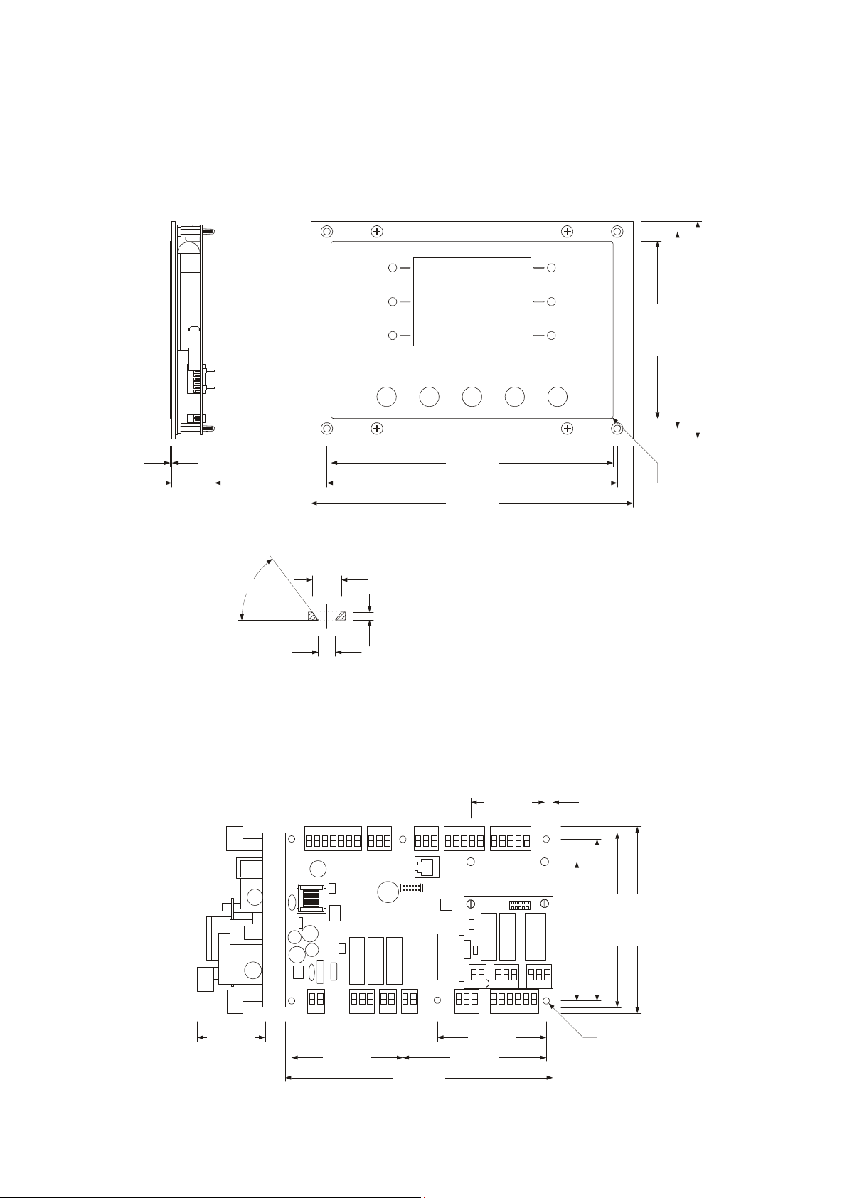
3 DIMENSIONS AND INSTALLATION
3.1 User interface dimensions
The following drawing illustrates the EVFTFT818 user interface dimensions; these are expressed in mm (in).
1,0 ±0,6 (0,039 ±0,023)
27,0 (1,062)
particolare A
°
3
5
4,2 (0,165)
7,2 (0,283)
2.0 (0.078)
3.2 Control module dimensions
The following drawing illustrates the EVFTFT818 control module dimensions; these are expressed in mm (in).
5,0 (0,196)46,0 (1,811)
68,0 (2,677)44,0 (1,732)
69,0 (2,716) 89,0 (3,503)
166,0 (6,535)
page 14 of 94
Page 15

EVCO S.p.A. EVFTFT818 | Installer manual ver. 2.1 | Code 144FTFT818E214
3.3 User interface installation
Back panel via studs.
3.4 Control module installation
On flat surface, with spacers.
3.5 Installation warnings
- make sure that the device work conditions (temperature of use, humidity, etc.) lie within the limits indicated;
see chapter 15 "TECHNICAL DATA"
- do not install the device near to any heat sources (heating elements, hot air ducts etc.), equipment containing
powerful magnets (large diffusers, etc), areas affected by direct sunlight, rain, humidity, excessive dust,
mechanical vibrations or shocks.
- any metal parts in proximity of the control module must be at a distance such that they do not compromise the
safety distances; possible wirings must be located at 2 cm (0.787 in) at least
- in compliance with Safety Standards, the device must be installed correctly and in a way to protect against any
contact with electric parts; all parts that ensure protection must be fixed in a way that they cannot be removed
without the use of tools.
page 15 of 94
Page 16
EVCO S.p.A. EVFTFT818 | Installer manual ver. 2.1 | Code 144FTFT818E214
4 ELECTRIC CONNECTION
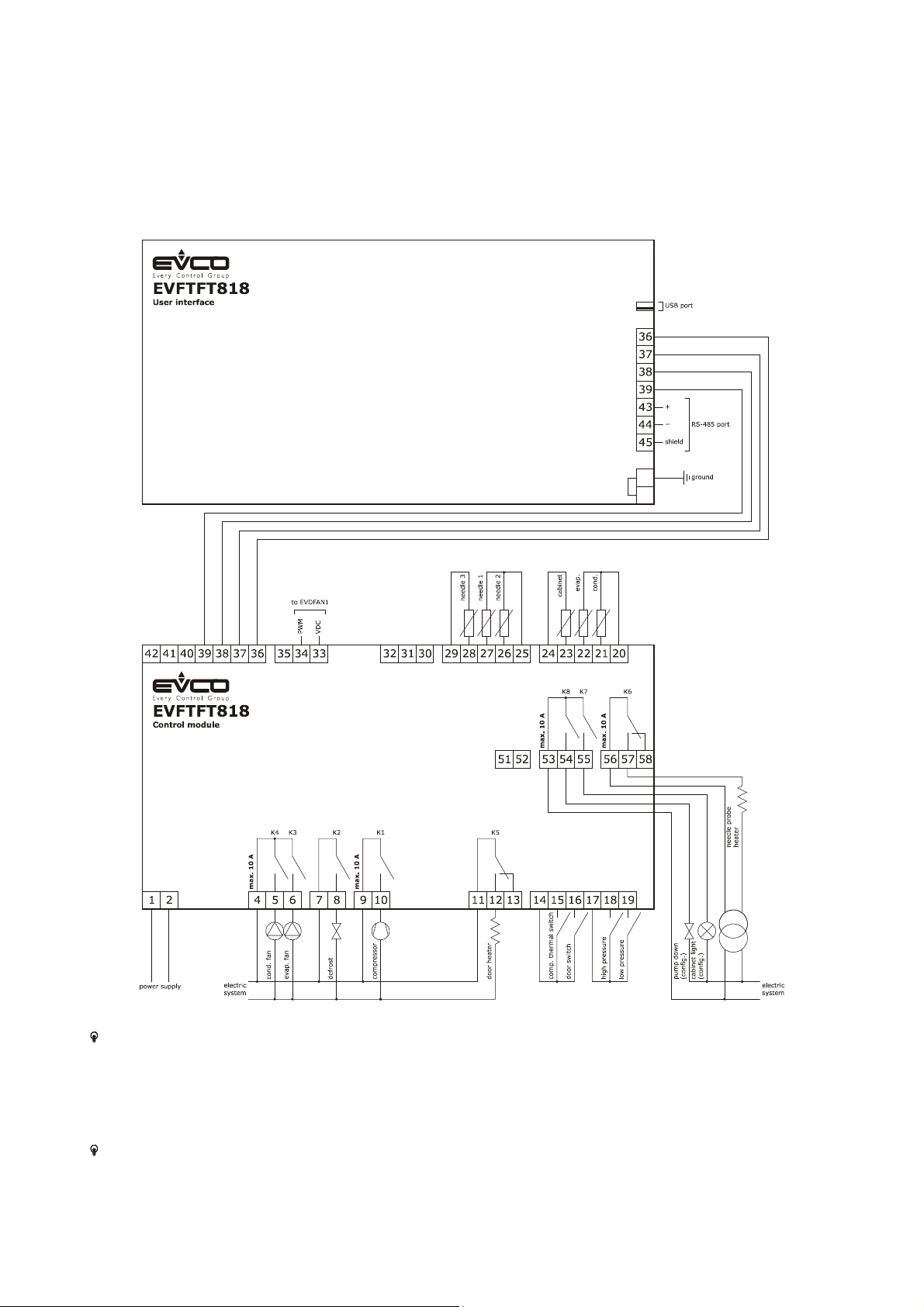
4.1 Electric connection
The following drawing illustrates the EVFTFT818 electric connection.
The utility managed by the K7 output, depends on parameter u11, as follows:
- cabinet light (u11 = 0, pre-defined setting)
- UV light (u11 = 1).
For the settings relative to the parameters, see chapter 10 “CONFIGURATION”.
The utility managed by the K8 output, depends on parameter u1, as follows:
- pump down valve (u1 = 0, per-defined setting)
- alarm (u1 = 1).
page 16 of 94
Page 17
EVCO S.p.A. EVFTFT818 | Installer manual ver. 2.1 | Code 144FTFT818E214
For the settings relative to the parameters, see chapter 10 “CONFIGURATION”.
The RS-485 port is for the connection of the controller to the following additional products:
- Parameters Manager set-up software system
- RICS plants monitoring and surveillance systems
- device for recording data and to download recorded data (via USB) EVUSBREC01.
The port must not be used simultaneously with more than one of these products.
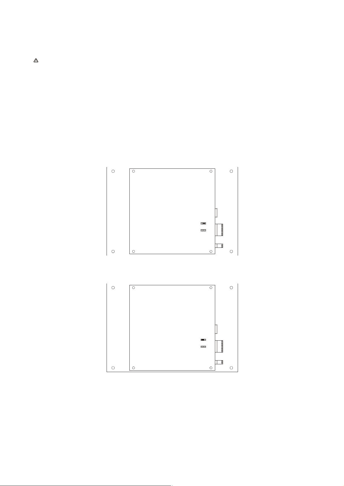
4.1.1 Insertion of the user interface-control module terminating
resistor
The terminating resistor must be connected in order to reduce the reflections on the signal transmitted along the
cables that connect the user interface to the control model.
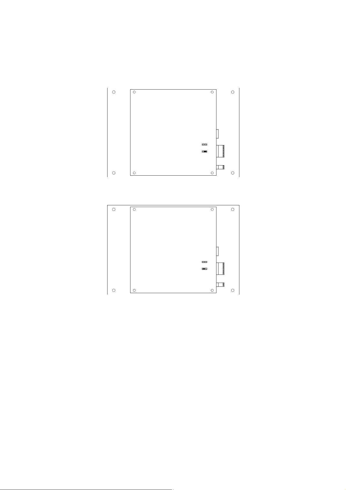
To connect the terminating resistors, position the jumper as illustrated in the following drawing.
To disconnect the terminating resistors, position the jumper as illustrated in the following drawing.
page 17 of 94
Page 18
EVCO S.p.A. EVFTFT818 | Installer manual ver. 2.1 | Code 144FTFT818E214
4.1.2 Insertion of the RS-485 serial port terminating resistor
The terminating resistor must be inserted in order to reduce the reflections on the signal transmitted along the cables
that connect the RS-485 serial port to other EVCO products.
To connect the terminating resistors, position the jumper as illustrated in the following drawing.
To disconnect the terminating resistors, position the jumper as illustrated in the following drawing.
4.2 Warnings for the electric connection
- do not use electric or pneumatic screwdrivers on the device terminal board
- if the device has been taken from a cold to hot place, humidity could condense inside; wait about 1 hour before
powering it
- make sure that the power supply voltage, the frequency and the operational electric power of the device,
correspond with those of the local power supply; see chapter 15 "TECHNICAL DATA"
- disconnect the device power supply before proceeding with any type of maintenance
- do not use this device as a safety device
- for repairs and information regarding the device, contact the EVCO sales network.
page 18 of 94
Page 19
EVCO S.p.A. EVFTFT818 | Installer manual ver. 2.1 | Code 144FTFT818E214
5 USER INTERFACE
5.1 Foreword
The following operating status exist:
- the “off” status (the device is not powered)
- the “stand-by” status (the device is powered and is off)
- the “on” status (the device is powered, is on and is in stand-by for the start-up of an operating cycle)
- the “run” status (the device is powered, is on and an operating cycle is in progress).
Hereon, the term "device switch-on" means the passage from the "stand-by" status to the "on" status. the term
"switch-off" means passage from the "on" status to the "stand-by" status.
If a power cut occurs during the "stand-by" status or during the "on" status, the device will re-propose the same
status when the power supply is restored.
If a power cut occurs during the "run" status, the device will operate as follows when this is restored:
- if a temperature-controlled blast chilling or deep freezing operation was in progress, these will be started again
from the beginning
- if a timed-controlled blast chilling or deep freezing operation was in progress, these will be started again from
the moment the power supply was cut-off
- if storage was in progress, this will be re-proposed.
5.2 Device commissioning
Operate as follows:
1. Connect the device power supply. if parameter E9 is set at 1, the device will display the EVCO splash screen for
10 s, after which it will go to the “stand-by” status.
page 19 of 94
Page 20
EVCO S.p.A. EVFTFT818 | Installer manual ver. 2.1 | Code 144FTFT818E214
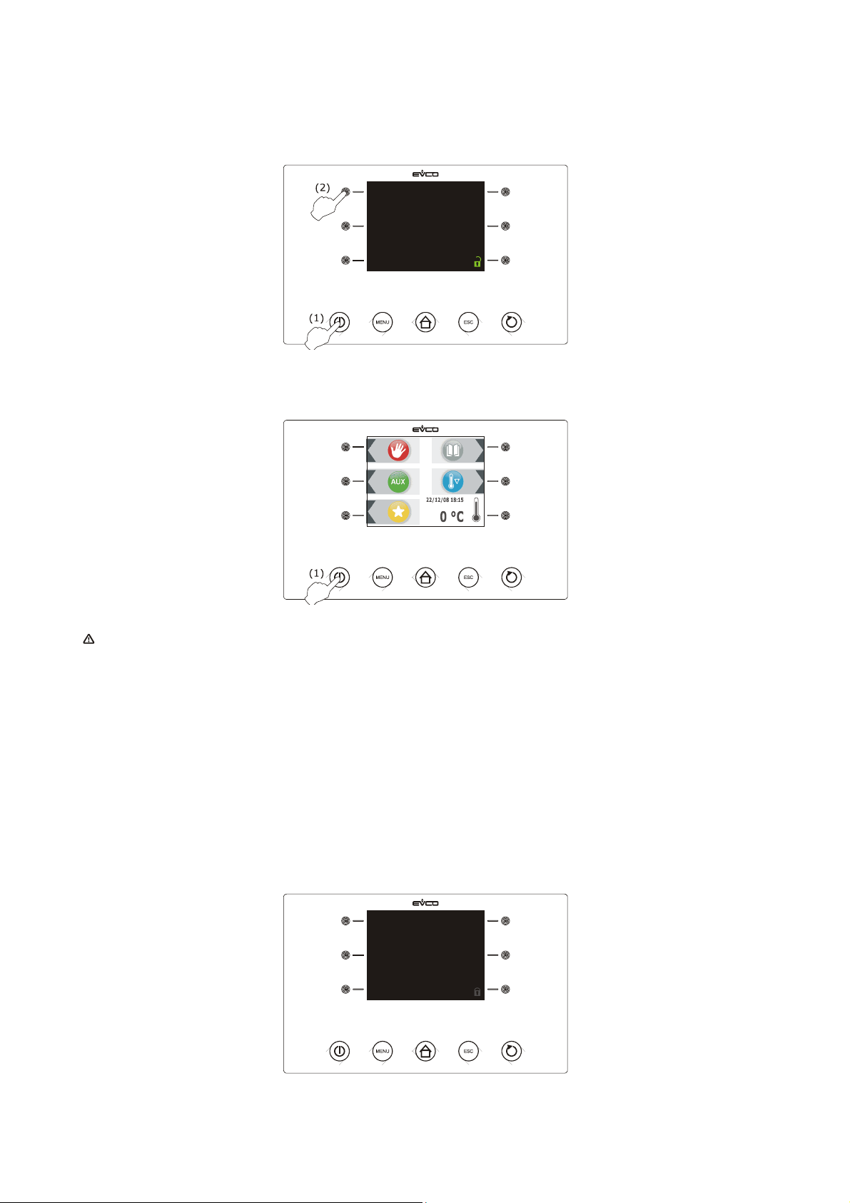
2. Press and release the ON/STAND-BY key (1) and then press the highest interactive key on the left (2) to unlock
the keyboard.
3. Press and release the ON/STAND-BY (1) key.
If the duration of the power cut has been such to cause the clock error (“rtc” code), the real day and time will
have to be reset; see paragraph 10.1 “Setting the real day and time”.
5.3 Switching the device on/off
Operate as follows:
1. Make sure that the keyboard is not locked and that no procedure is in progress.
2. Press and release the ON/STAND-BY key.
5.4 The display
The display is off during the "off" status and during the "stand-by" status.
page 20 of 94
Page 21
EVCO S.p.A. EVFTFT818 | Installer manual ver. 2.1 | Code 144FTFT818E214
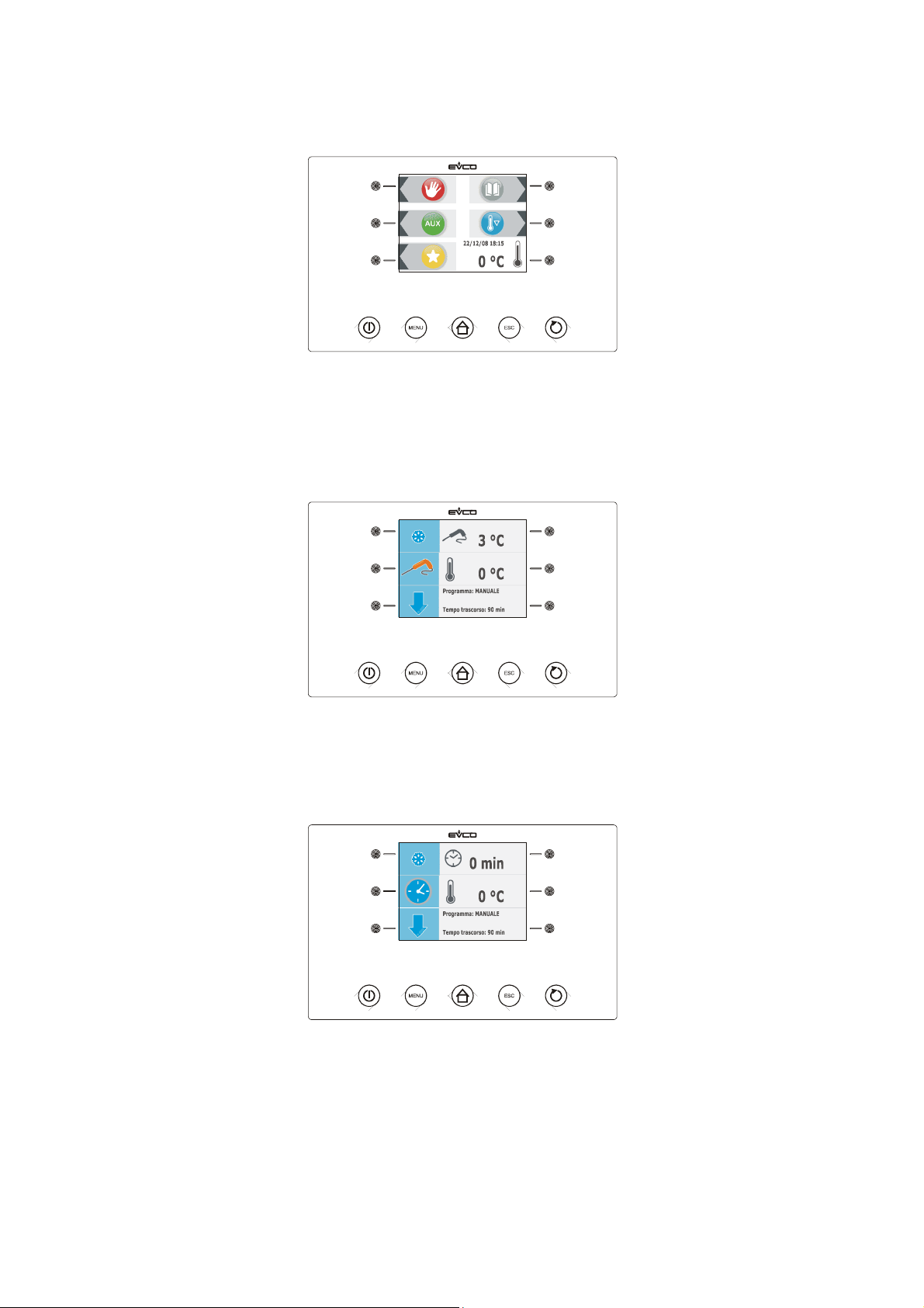
During the “on” status, the device will display the real day and time and the temperature of the cabinet.
During the "run" state the device will display:
- if a temperature-controlled blast chilling or deep freezing operation is in progress, the temperature detected by
the needle probe, the temperature of the cabinet, the name of the program, (if envisioned) and the time
passed from the start of blast chilling or deep freezing.
- if a time-controlled blast chilling or deep freezing operation is in progress, the residual duration of the blast
chilling or deep freezing, the temperature of the cabinet, the name of the program, (if envisioned) and the time
passed from the start of blast chilling or deep freezing
page 21 of 94
Page 22
EVCO S.p.A. EVFTFT818 | Installer manual ver. 2.1 | Code 144FTFT818E214
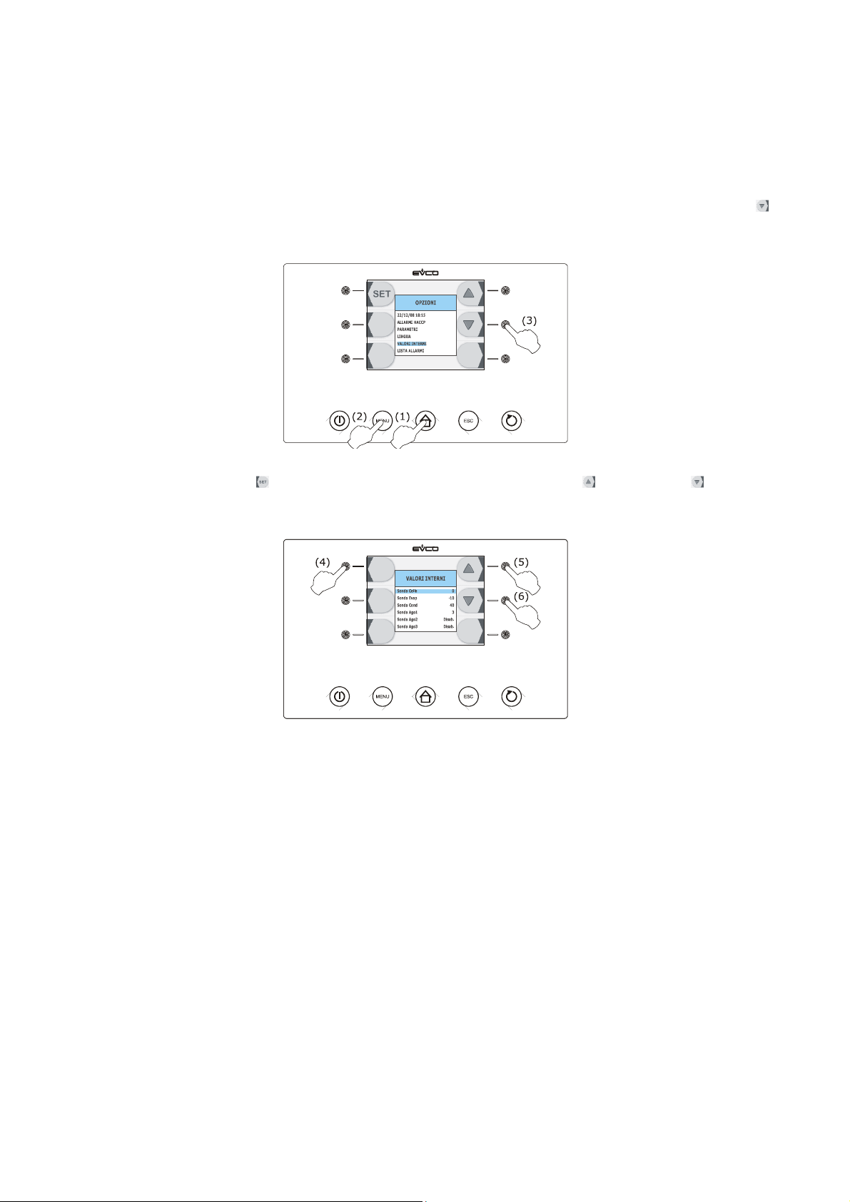
5.5 Display of inputs and outputs status
Operate as follows:
1. Make sure that the instrument is in the “on” status.
2. Make sure that the keyboard is not locked and that no procedure is in progress.
3. Press and release the HOME key (1), press and release the MENU key (2) and then press and release the
key repeatedly (3) in order to select the “INTERNAL VALUES”.
4. Press and release the key (4) and then repeatedly press and release the key (5) or the key (6) to
select the input or the output.
Operate as follows to exit the procedure:
5. Press and release the ESCAPE key or do not operate for 60 s.
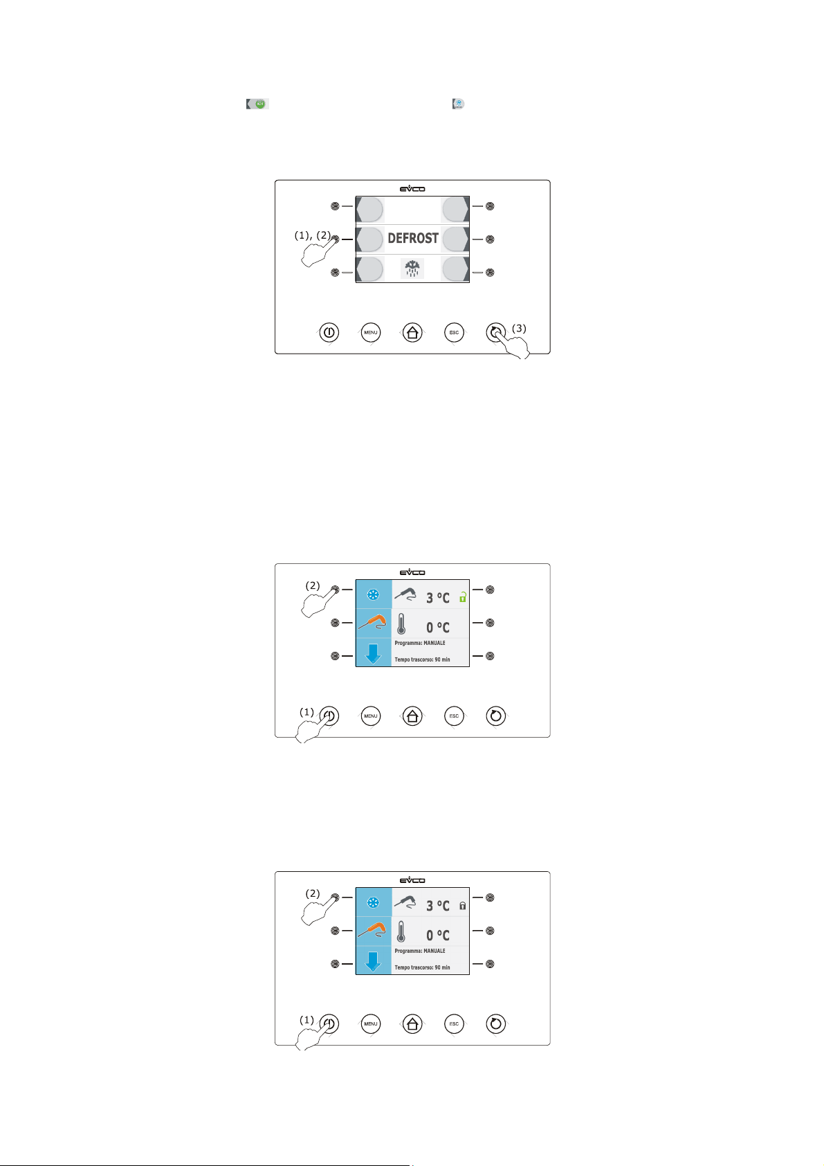
5.6 Defrosting activation in manual mode
Operate as follows:
1. Make sure the device is in the "on" status, that pre-cooling or storage cycle is in progress.
2. Make sure that the keyboard is not locked and that no procedure is in progress.
page 22 of 94
Page 23
EVCO S.p.A. EVFTFT818 | Installer manual ver. 2.1 | Code 144FTFT818E214
3. Press and release the key (1), press and release the key (2) and then press and release the START /
STOP (3) key.
If the evaporator probe is enabled, i.e. the parameter P4 is set at 1 and on activation of defrosting the evaporator
temperature is above that established with parameter d2, defrosting will not be activated.
5.7 Locking/unlocking of the keyboard
Operate as follows to lock the keyboard:
1. Make sure parameter E8 is set to 1 and no procedures are in progress.
2. Press and release the ON/STAND-BY key (1) and then press the highest interactive key on the left (2).
If parameter E8 is set to 2, on expiry of 60 s the keybord will automatically lock.
Operate as follows to unlock the keyboard:
1. Make sure no procedures are in progress
2. Press and release the ON/STAND-BY key (1) and then press the highest interactive key on the left (2).
page 23 of 94
Page 24

EVCO S.p.A. EVFTFT818 | Installer manual ver. 2.1 | Code 144FTFT818E214
Silencing the buzzer
Operate as follows:
1. Make sure no procedures are in progress
2. Press and release the key.
page 24 of 94
Page 25

EVCO S.p.A. EVFTFT818 | Installer manual ver. 2.1 | Code 144FTFT818E214
6 OPERATION
6.1 Foreword
The device can manage the following operating cycles:
- temperature-controlled blast chilling and storage
- temperature-controlled hard blast chilling and storage
- time-controlled blast chilling and storage
- time-controlled hard blast chilling and storage
- continuous blast chilling
- temperature-controlled deep freezing and storage
- temperature-controlled soft deep freezing and storage
- time-controlled deep freezing and storage
- time-controlled soft deep freezing and storage
- continuous deep freezing
For further information, see the next paragraphs
Every operating cycle can be preceded by pre-cooling; see paragraph 6.13 "Pre-cooling start-up".
The temperature-controlled cycles are preceded by a test to verify the correct insertion of the needle probe; see
paragraph 6.14 " Test for verification of the correct insertion of the needle probe".
If the needle probe is not enabled, i.e. if parameter P3 is set at 0, the temperature-controlled cycles will be started
with time-control.
The following functions can also be used:
- switching on sterilisation cycle UV light
- heating the needle probe.
For further information, see the next paragraphs
6.1.1 Foreword regarding needle probe
The device can manage "multipoint" needle probes (with up to three sensors".
Parameter P3 establishes the number of needle probe sensors as indicated:
- if parameter P3 is set at 0, the needle probe will not be enabled
- if parameter P3 is set at 1, there will be one sensor (needle probe 1)
- if parameter P3 is set at 2, there will be 2 sensors (needle probe 1 and needle probe 2)
- if parameter P3 is set at 3, there will be 3 sensors (needle probe 1 and needle probe 2 and needle probe 3).
If parameter P3 is set at values different to 0, the temperature-controlled cycles will be preceded by a test to verify
the correct insertion of the needle probe; see paragraph 6.14 " Test for verification of the correct insertion of the
needle probe".
On conclusion of the test, the device will operate as indicated:
- the sensor that has detected the lowest temperature is then used as the reference temperature for heating the
needle probe.
- the sensor that has detected the highest temperature is then used as the reference for the temperature-
controlled cycles
- the sensors for which the test is not completed successfully are not used successively.
page 25 of 94
Page 26
EVCO S.p.A. EVFTFT818 | Installer manual ver. 2.1 | Code 144FTFT818E214
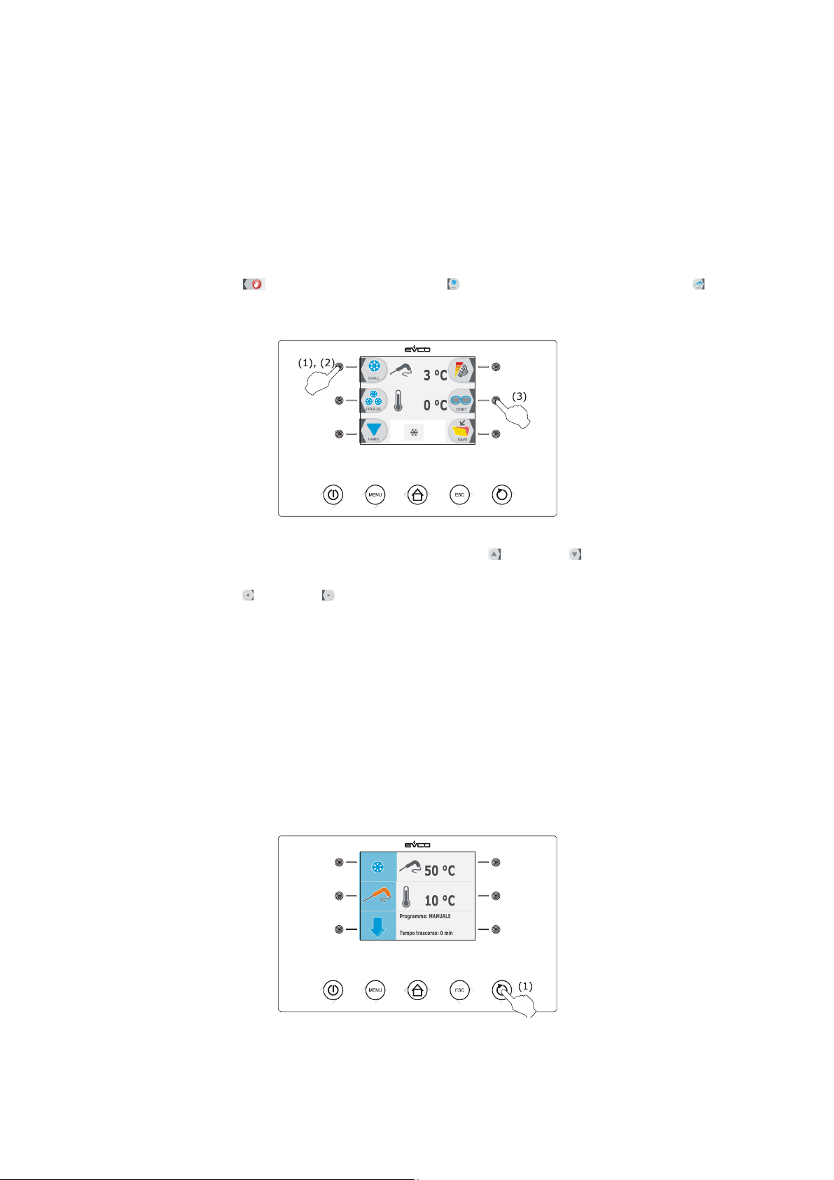
6.2 Temperature-controlled blast chilling and storage
The temperature-controlled blast chilling and storage cycle is divided into the following two phases:
- blast chilling
- storage.
On conclusion of a phase, the device passes automatically to the next.
Operate as indicated to start the cycle:
1. Make sure the device is in the "on" status.
2. Make sure that the keyboard is not locked and that no procedure is in progress.
3. Press and release the key (1), press and release the key (2) and then press and release the key (3).
the device will display the blast chilling end temperature and the work set-point during blast chilling.
4.1 Press and release the MENU key and then press and release the key or the key to select the blast chilling
end temperature and the work set-point during blast chilling.
4.2 Press and release the key or the key to modify these values and then the ESCAPE key to memorise them;
these values can also be memorised through parameters r3 and r7.
5. Press and release the START/STOP key (1): the test to verify the correct insertion of the needle probe will be
started; see paragraph 6.14 " Test for verification of the correct insertion of the needle probe".
5.1 If the test is completed successfully, the cycle will be started.
The maximum blast chilling duration count is started on condition that the temperature detected by the
needle probe is below that established with parameter r15.
5.2 If the test is not completed successfully, the buzzer will be activated for 5 s every 60 s and the cycle will
be started with timed-control; see paragraph 6.4 "Time-controlled blast chilling and storage".
During blast chilling the device displays the temperature detected by the needle probe, the cabinet temperature, the
program name (if envisioned) and the time passed since the start of blast chilling.
Operate as indicated to stop the cycle:
6. Press and hold the START/STOP key 3 s.
page 26 of 94
Page 27
EVCO S.p.A. EVFTFT818 | Installer manual ver. 2.1 | Code 144FTFT818E214
The successive parameters establish the following values:
- parameter r3 establishes the blast chilling end temperature
- parameter r5 establishes the maximum blast chilling duration
- parameter r7 establishes the work set-point during blast chilling.
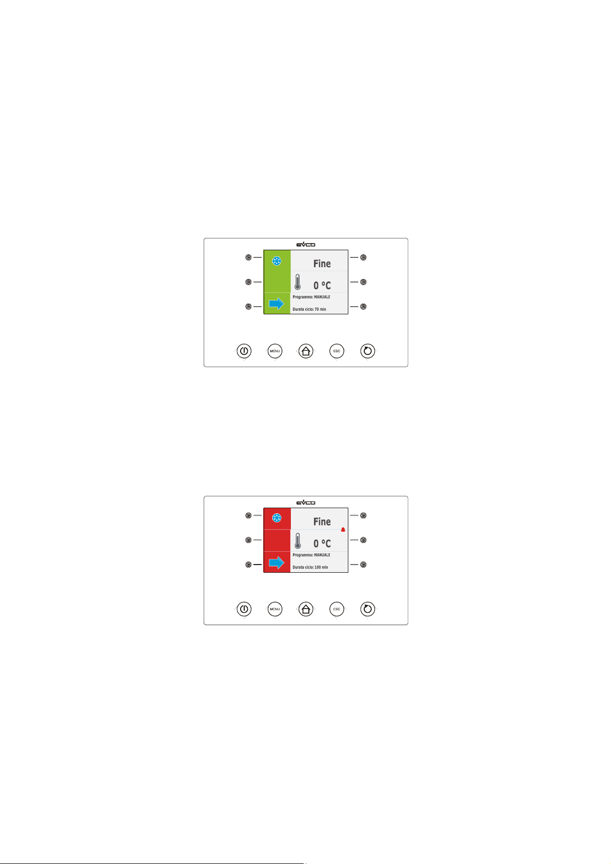
If the temperature detected by the needle probe reaches the blast chilling end temperature within the maximum blast
chilling duration, it means that blast chilling has been completed successfully, the device will automatically pass to
storage and the buzzer will be activated for the period of time established with parameter AA.
Press and release a key to silence the buzzer.
During storage the device displays the temperature of the cabinet, the program name (if envisioned) and the time
taken to complete blast chilling successfully.
Parameter r10 establishes the work set-point during storage.
If the temperature detected by the needle probe does not reach the blast chilling end temperature within the maximum
blast chilling duration, blast chilling will not be completed successfully but will continue and the buzzer will be activated.
Press and release a key to restore normal display and to silence the buzzer.
When the temperature detected by the needle probe reaches the blast chilling end temperature, the device
automatically passes to storage in the same way as illustrated previously.
6.3 Temperature-controlled hard blast chilling and storage
The temperature-controlled hard blast chilling and storage cycle is divided into the following three phases:
- blast chilling hard phase
- blast chilling
- storage.
On conclusion of a phase, the device passes automatically to the next.
Operate as indicated to start the cycle:
1. Make sure the device is in the "on" status.
2. Make sure that the keyboard is not locked and that no procedure is in progress.
page 27 of 94
Page 28
EVCO S.p.A. EVFTFT818 | Installer manual ver. 2.1 | Code 144FTFT818E214
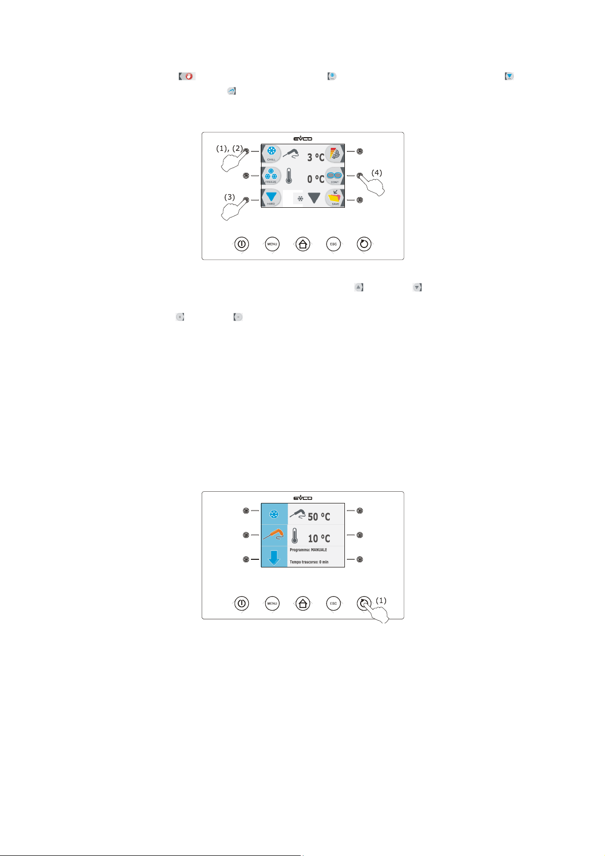
3. Press and release the key (1), press and release the key (2) and then press and release the key (3)
and finally press and release the key (4): the device will display the blast chilling end temperature and the
work set-point during blast chilling.
4.1 Press and release the MENU key and then press and release the key or the key to select the blast chilling
end temperature and the work set-point during blast chilling.
4.2 Press and release the key or the key to modify these values and then the ESCAPE key to memorise them;
these values can also be memorised through parameters r3 and r7.
5. Press and release the START/STOP key (1): the test to verify the correct insertion of the needle probe will be
started; see paragraph 6.14 " Test for verification of the correct insertion of the needle probe".
5.1 If the test is completed successfully, the cycle will be started.
The maximum blast chilling duration count is started on condition that the temperature detected by the
needle probe is below that established with parameter r15.
5.2 If the test is not completed successfully, the buzzer will be activated for 5 s every 60 s and the cycle will
be started with timed-control; see paragraph 6.4 "Time-controlled hard blast chilling and storage".
During hard blast chilling phase the device displays the temperature detected by the needle probe, the cabinet
temperature, the program name (if envisioned) and the time passed since the start of blast chilling .
Operate as indicated to stop the cycle:
6. Press and hold the START/STOP key 3 s.
The successive parameters establish the following values:
- parameter r5 establishes the maximum blast chilling duration
- parameter r9 establishes the work set-point during the blast chilling hard phase
- parameter r13 establishes blast chilling hard phase end temperature.
When the temperature detected by the needle probe reaches the hard blast chilling phase end temperature, the device
automatically passes to blast chilling mode.
During blast chilling the device displays the temperature detected by the needle probe, the cabinet temperature, the
program name (if envisioned) and the time passed since the start of blast chilling.
page 28 of 94
Page 29
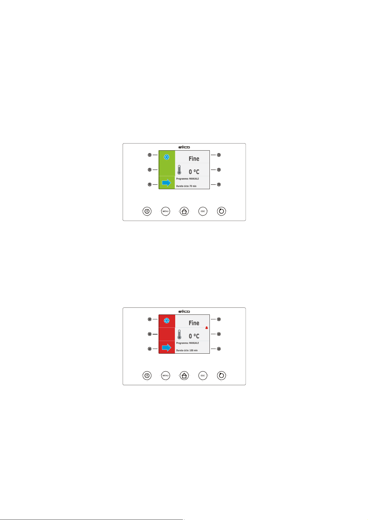
EVCO S.p.A. EVFTFT818 | Installer manual ver. 2.1 | Code 144FTFT818E214
The successive parameters establish the following values:
- parameter r3 establishes the blast chilling end temperature
- parameter r5 establishes the maximum blast chilling duration
- parameter r7 establishes the work set-point during blast chilling.
If the temperature detected by the needle probe reaches the blast chilling end temperature within the maximum blast
chilling duration, it means that blast chilling has been completed successfully, the device will automatically pass to
storage and the buzzer will be activated for the period of time established with parameter AA.
Press and release a key to silence the buzzer.
During storage the device displays the temperature of the cabinet, the program name (if envisioned) and the time
taken to complete blast chilling successfully.
Parameter r10 establishes the work set-point during storage.
If the temperature detected by the needle probe does not reach the blast chilling end temperature within the
maximum blast chilling duration, blast chilling will not be completed successfully but will continue and the buzzer will
be activated.
Press and release a key to restore normal display and to silence the buzzer.
When the temperature detected by the needle probe reaches the blast chilling end temperature, the device
automatically passes to storage in the same way as illustrated previously.
6.4 Time-controlled blast chilling and storage
The time-controlled blast chilling and storage cycle is divided into the following two phases:
- blast chilling
- storage.
On conclusion of a phase, the device passes automatically to the next.
Operate as indicated to start the cycle:
1. Make sure the device is in the "on" status.
2. Make sure that the keyboard is not locked and that no procedure is in progress.
page 29 of 94
Page 30
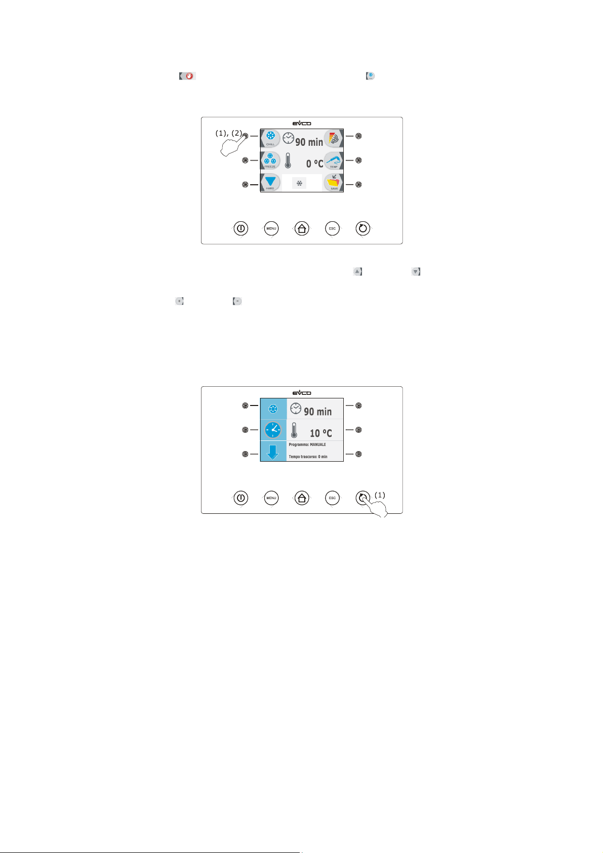
EVCO S.p.A. EVFTFT818 | Installer manual ver. 2.1 | Code 144FTFT818E214
3. Press and release the key (1) and then press and release the key (2): the device will display the blast
chilling duration and the work set-point during blast chilling.
4.1 Press and release the MENU key and then press and release the key or the key to select the blast chilling
duration and the work set-point during blast chilling.
4.2 Press and release the key or the key to modify these values and then the ESCAPE key to memorise them;
these values can also be memorised through parameters r1 and r7.
5. Press and release the START/STOP key (1): the cycle will be started.
During blast chilling the device displays the residual blast chilling time, the temperature of the cabinet, the name of
the program (if envisioned) and the time passed from the start of blast chilling.
Operate as indicated to stop the cycle:
6. Press and hold the START/STOP key 3 s.
The successive parameters establish the following values:
- parameter r1 establishes blast chilling duration
- parameter r7 establishes the work set-point during blast chilling.
On expiry of the blast chilling duration, the device automatically passes to storage mode and the buzzer is activated
for the time period established with parameter AA.
Press and release a key to silence the buzzer.
page 30 of 94
Page 31
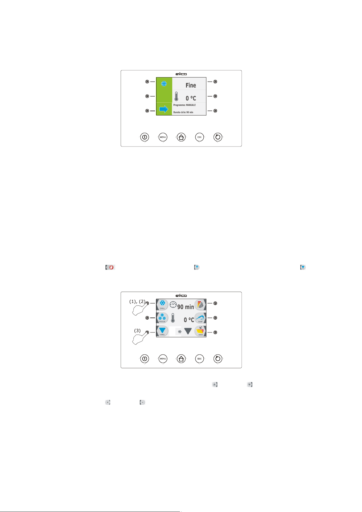
EVCO S.p.A. EVFTFT818 | Installer manual ver. 2.1 | Code 144FTFT818E214
During storage the device displays the temperature of the cabinet, the program name (if envisioned) and the duration
of blast chilling.
Parameter r10 establishes the work set-point during storage.
6.5 Time-controlled hard blast chilling and storage
The time-controlled hard blast chilling and storage cycle is divided into the following three phases:
- blast chilling hard phase
- blast chilling
- storage.
On conclusion of a phase, the device passes automatically to the next.
Operate as indicated to start the cycle:
1. Make sure the device is in the "on" status.
2. Make sure that the keyboard is not locked and that no procedure is in progress.
3. Press and release the key (1), press and release the key (2) and then press and release the key (3).
the device will display the blast chilling duration and the work set-point during blast chilling.
4.1 Press and release the MENU key and then press and release the key or the key to select the blast chilling
duration and the work set-point during blast chilling.
4.2 Press and release the key or the key to modify these values and then the ESCAPE key to memorise them;
these values can also be memorised through parameters r1 and r7.
5. Press and release the START/STOP key (1): the cycle will be started.
page 31 of 94
Page 32
EVCO S.p.A. EVFTFT818 | Installer manual ver. 2.1 | Code 144FTFT818E214
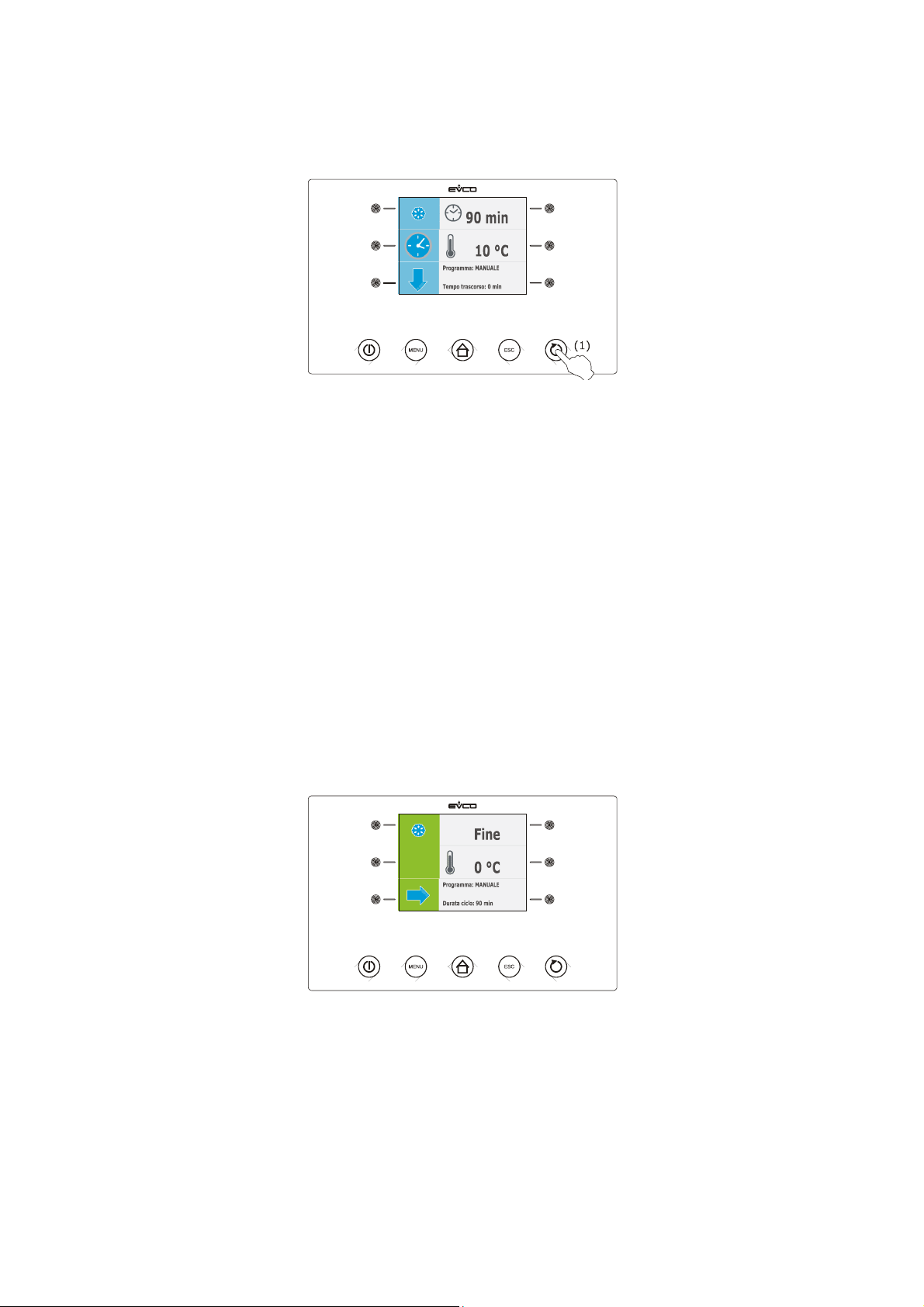
During hard blast chilling the device displays the residual blast chilling time, the temperature of the cabinet, the name
of the program (if envisioned) and the time passed from the start of blast chilling.
Operate as indicated to stop the cycle:
6. Press and hold the START/STOP key 3 s.
The successive parameters establish the following values:
- parameter r9 establishes the work set-point during the blast chilling hard phase
- parameter r14 establishes blast chilling hard phase duration.
On expiry of the hard blast chilling phase duration, the device automatically passes to blast chilling.
During blast chilling the device displays the residual blast chilling time, the temperature of the cabinet, the name of
the program (if envisioned) and the time passed from the start of blast chilling.
The successive parameters establish the following values:
- parameter r1 establishes blast chilling duration
- parameter r7 establishes the work set-point during blast chilling.
On expiry of the blast chilling duration, the device automatically passes to storage mode and the buzzer is activated
for the time period established with parameter AA.
Press and release a key to silence the buzzer.
During storage the device displays the temperature of the cabinet, the program name (if envisioned) and the duration
of blast chilling.
Parameter r10 establishes the work set-point during storage.
page 32 of 94
Page 33
EVCO S.p.A. EVFTFT818 | Installer manual ver. 2.1 | Code 144FTFT818E214
6.6 Continuous blast chilling
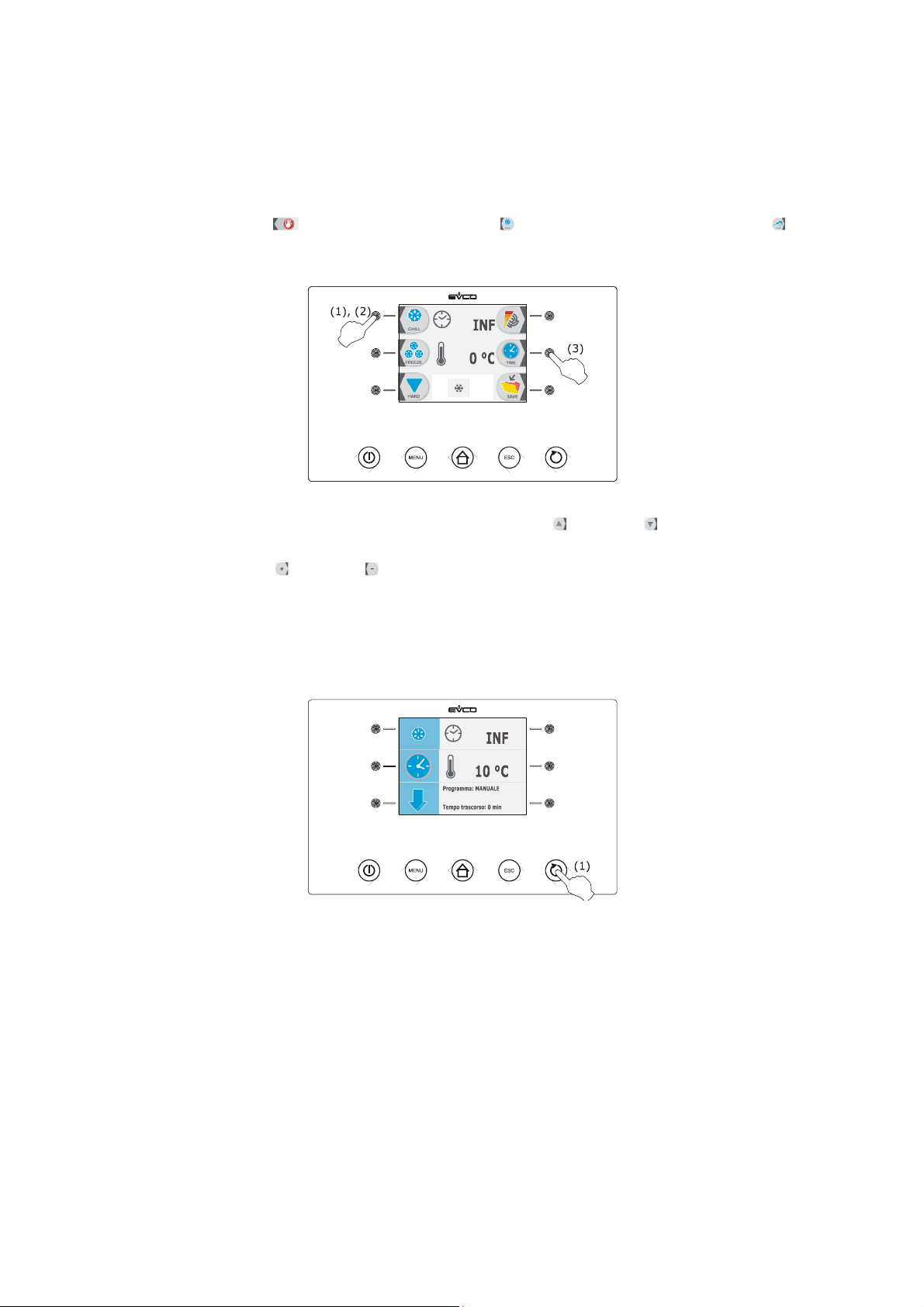
Operate as indicated to start the cycle:
1. Make sure the device is in the "on" status.
2. Make sure that the keyboard is not locked and that no procedure is in progress.
3. Press and release the key (1), press and release the key (2) and then press and release the key (3)
twice. The device will display the work set-point during blast chilling.
4.1 Press and release the MENU key and then press and release the key or the key to select the work set-
point during blast chilling.
4.2 Press and release the key or the key to modify this value and then the ESCAPE key to memorise it; this
value can also be memorised through parameters r1 and r7.
5. Press and release the START/STOP key (1): the cycle will be started.
During blast chilling the device displays the temperature of the cabinet, the program name (if envisioned) and the time
passed since the start of blast chilling.
Operate as indicated to stop the cycle:
6. Press and hold the START/STOP key 3 s.
Parameter r7 establishes the work set-point during blast chilling.
6.7 Temperature-controlled deep freezing and storage
The temperature-controlled deep freezing and storage cycle is divided into the following two phases:
- deep freezing
- storage.
On conclusion of a phase, the device passes automatically to the next.
Operate as indicated to start the cycle:
page 33 of 94
Page 34
EVCO S.p.A. EVFTFT818 | Installer manual ver. 2.1 | Code 144FTFT818E214
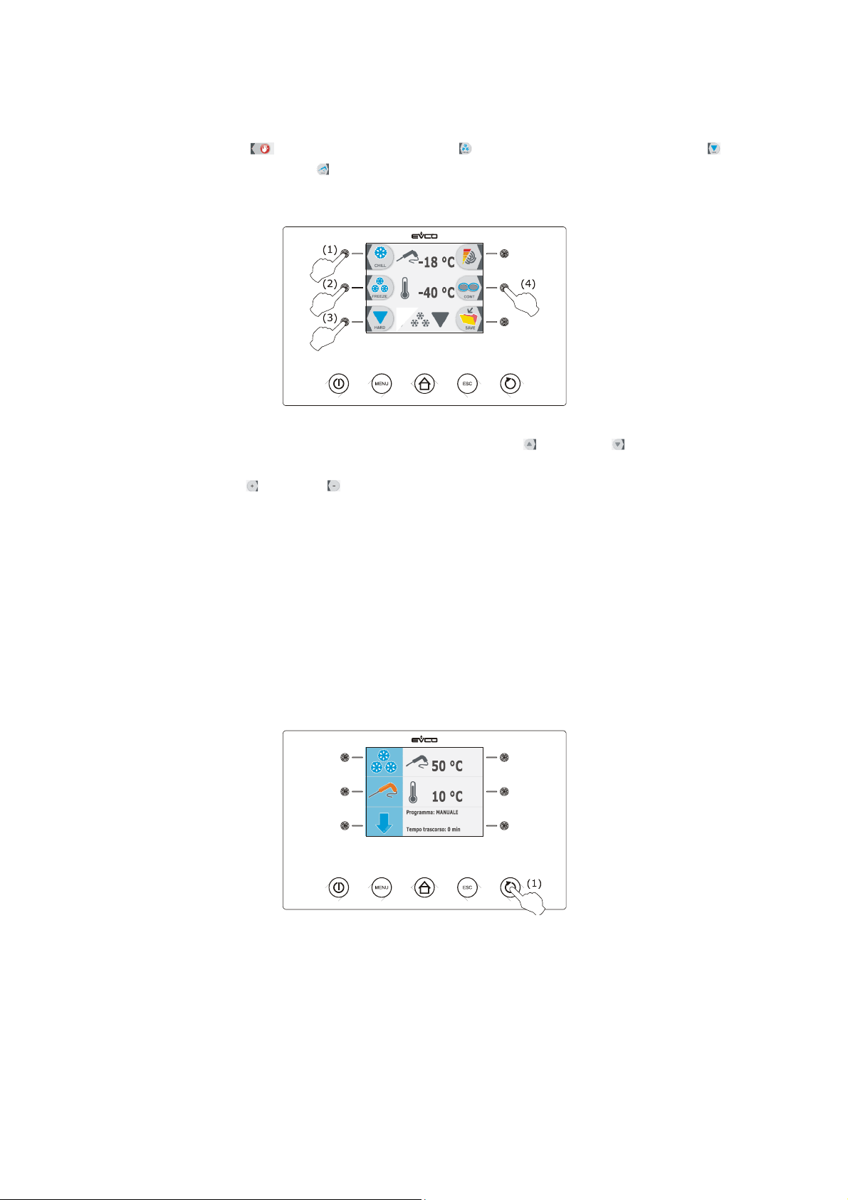
1. Make sure the device is in the "on" status.
2. Make sure that the keyboard is not locked and that no procedure is in progress.
3. Press and release the key (1), press and release the key (2) and then press and release the key (3)
and finally press and release the key (4): the device will display the deep freezing end temperature and the
work set-point during deep-freezing.
4.1 Press and release the MENU key and then press and release the key or the key to select the deep
freezing end temperature and the work set-point during deep freezing.
4.2 Press and release the key or the key to modify these values and then the ESCAPE key to memorise them;
these values can also be memorised through parameters r4 and r8.
5. Press and release the START/STOP key (1): the test to verify the correct insertion of the needle probe will be
started; see paragraph 6.14 " Test for verification of the correct insertion of the needle probe".
5.1 If the test is completed successfully, the cycle will be started.
The maximum deep freezing duration count is started on condition that the temperature detected by the
needle probe is below that established with parameter r15.
5.2 If the test is not completed successfully, the buzzer will be activated for 5 s every 60 s and the cycle will
be started with timed-control; see paragraph 6.9 "Time-controlled deep freezing and storage".
During deep freezing the device displays the temperature detected by the needle probe, the cabinet temperature, the
program name (if envisioned) and the time passed since the start of deep freezing.
Operate as indicated to stop the cycle:
6. Press and hold the START/STOP key 3 s.
The successive parameters establish the following values:
- parameter r4 establishes the deep freezing end temperature
- parameter r6 establishes the maximum deep freezing duration
- parameter r8 establishes the work set-point during deep freezing.
page 34 of 94
Page 35
EVCO S.p.A. EVFTFT818 | Installer manual ver. 2.1 | Code 144FTFT818E214
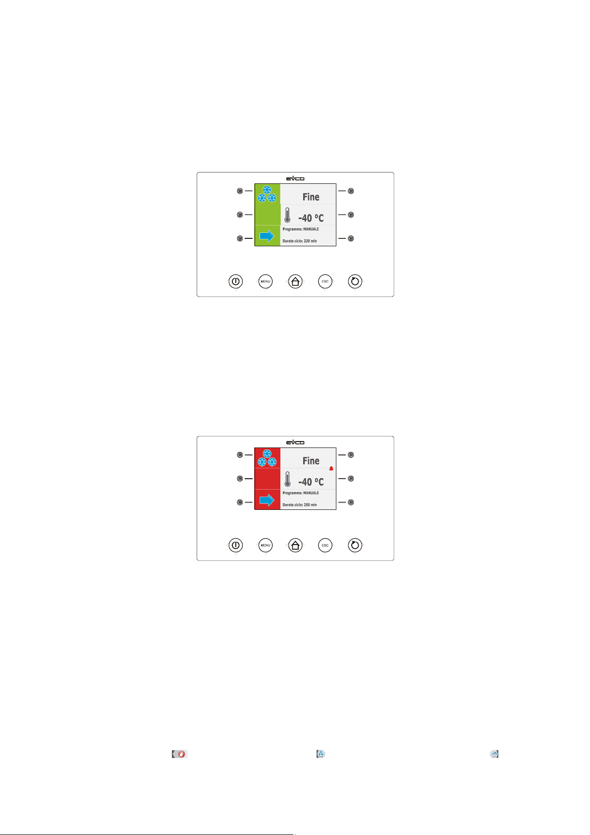
If the temperature detected by the needle probe reaches the deep freezing end temperature within the maximum deep
freezing duration, it means that deep freezing has been completed successfully, the device will automatically pass to
storage and the buzzer will be activated for the period of time established with parameter AA.
Press and release a key to silence the buzzer.
During storage the device displays the temperature of the cabinet, the program name (if envisioned) and the time
taken to complete deep freezing successfully.
Parameter r11 establishes the work set-point during storage.
If the temperature detected by the needle probe does not reach the deep freezing end temperature within the
maximum deep freezing duration, deep freezing will not be completed successfully but will continue and the buzzer will
be activated.
Press and release a key to restore normal display and to silence the buzzer.
When the temperature detected by the needle probe reaches the deep freezing end temperature, the device
automatically passes to storage in the same way as illustrated previously.
6.8 Temperature-controlled soft deep freezing and
storage
The temperature-controlled soft deep freezing and storage cycle is divided into the following three phases:
- deep freezing soft phase
- deep freezing
- storage.
On conclusion of a phase, the device passes automatically to the next.
Operate as indicated to start the cycle:
1. Make sure the device is in the "on" status.
2. Make sure that the keyboard is not locked and that no procedure is in progress.
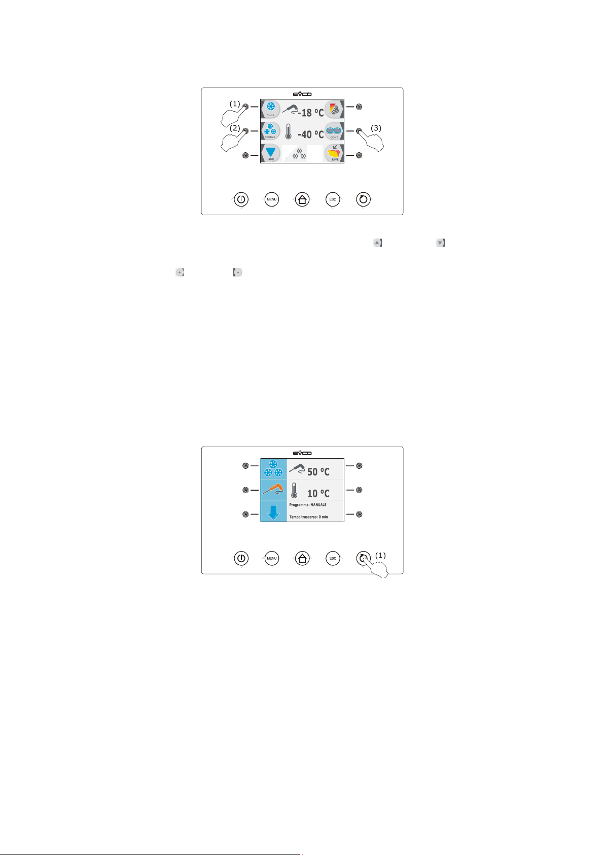
3. Press and release the key (1), press and release the key (2) and then press and release the key (3).
The device will display the deep freezing end temperature and the work set-point during deep-freezing.
page 35 of 94
Page 36
EVCO S.p.A. EVFTFT818 | Installer manual ver. 2.1 | Code 144FTFT818E214
4.1 Press and release the MENU key and then press and release the key or the key to select the deep
freezing end temperature and the work set-point during deep freezing.
4.2 Press and release the key or the key to modify these values and then the ESCAPE key to memorise them;
these values can also be memorised through parameters r4 and r8.
5. Press and release the START/STOP key (1): the test to verify the correct insertion of the needle probe will be
started; see paragraph 6.14 " Test for verification of the correct insertion of the needle probe".
5.1 If the test is completed successfully, the cycle will be started.
The maximum deep freezing duration count is started on condition that the temperature detected by the
needle probe is below that established with parameter r15.
5.2 If the test is not completed successfully, the buzzer will be activated for 5 s every 60 s and the cycle will
be started with timed-control; see paragraph 6.10 "Time-controlled soft deep freezing and storage".
During the soft deep freezing phase the device displays the temperature detected by the needle probe, the cabinet
temperature, the program name (if envisioned) and the time passed since the start of deep freezing.
Operate as indicated to stop the cycle:
6. Press and hold the START/STOP key 3 s.
The successive parameters establish the following values:
- parameter r3 establishes deep freezing soft phase end temperature.
- parameter r6 establishes the maximum deep freezing duration
- parameter r7 establishes the work set-point during the deep freezing soft phase.
When the temperature detected by the needle probe reaches the end temperature of the soft deep freezing phase, the
device automatically passes to deep freezing.
During deep freezing the device displays the temperature detected by the needle probe, the cabinet temperature, the
program name (if envisioned) and the time passed since the start of deep freezing.
The successive parameters establish the following values:
- parameter r4 establishes the deep freezing end temperature
- parameter r6 establishes the maximum deep freezing duration
page 36 of 94
Page 37
EVCO S.p.A. EVFTFT818 | Installer manual ver. 2.1 | Code 144FTFT818E214
- parameter r8 establishes the work set-point during deep freezing.
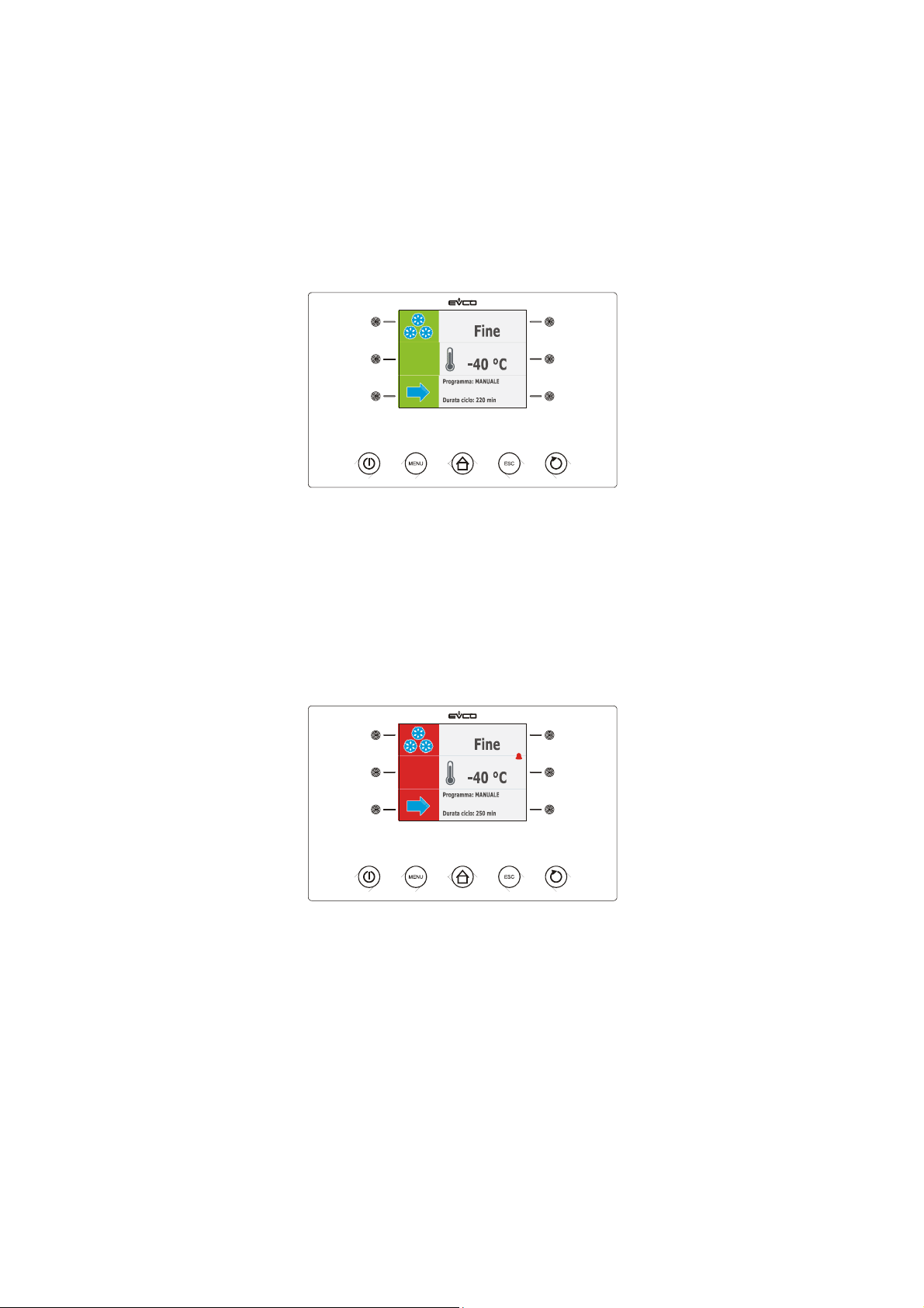
If the temperature detected by the needle probe reaches the deep freezing end temperature within the maximum deep
freezing duration, it means that deep freezing has been completed successfully, the device will automatically pass to
storage and the buzzer will be activated for the period of time established with parameter AA.
Press and release a key to silence the buzzer.
During storage the device displays the temperature of the cabinet, the program name (if envisioned) and the time
taken to complete deep freezing successfully.
Parameter r11 establishes the work set-point during deep freezing.
If the temperature detected by the needle probe does not reach the deep freezing end temperature within the
maximum deep freezing duration, deep freezing will not be completed successfully but will continue and the buzzer will
be activated.
Press and release a key to restore normal display and to silence the buzzer.
When the temperature detected by the needle probe reaches the deep freezing end temperature, the device
automatically passes to storage in the same way as illustrated previously.
6.9 Time-controlled deep freezing and storage
The time-controlled deep freezing and storage cycle is divided into the following two phases:
- deep freezing
- storage.
On conclusion of a phase, the device passes automatically to the next.
Operate as indicated to start the cycle:
1. Make sure the device is in the "on" status.
2. Make sure that the keyboard is not locked and that no procedure is in progress.
page 37 of 94
Page 38
EVCO S.p.A. EVFTFT818 | Installer manual ver. 2.1 | Code 144FTFT818E214
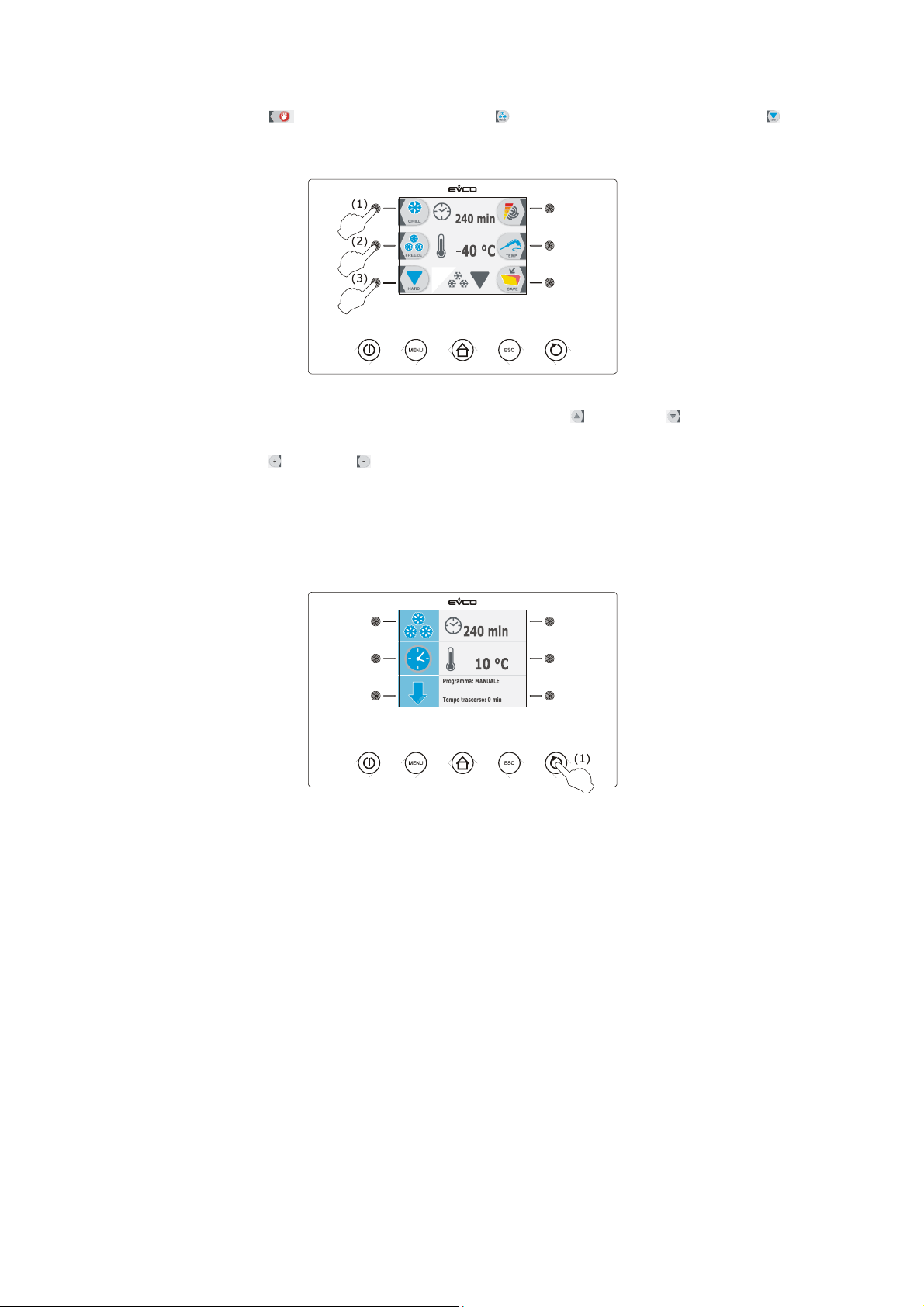
3. Press and release the key (1), press and release the key (2) and then press and release the key (3).
The device will display the duration of deep freezing and the work set-point during deep-freezing.
4.1 Press and release the MENU key and then press and release the key or the key to select the deep
freezing duration and the work set-point during deep freezing.
4.2 Press and release the key or the key to modify these values and then the ESCAPE key to memorise them;
these values can also be memorised through parameters r2 and r8.
5. Press and release the START/STOP key (1): the cycle will be started.
During blast chilling the device displays the residual deep freezing time, the temperature of the cabinet, the name of
the program (if envisioned) and the time passed from the start of deep freezing.
Operate as indicated to stop the cycle:
6. Press and hold the START/STOP key 3 s.
The successive parameters establish the following values:
- parameter r2 establishes deep freezing duration
- parameter r8 establishes the work set-point during deep freezing.
On expiry of the deep freezing duration, the device automatically passes to storage mode and the buzzer is activated
for the time period established with parameter AA.
Press and release a key to silence the buzzer.
page 38 of 94
Page 39
EVCO S.p.A. EVFTFT818 | Installer manual ver. 2.1 | Code 144FTFT818E214
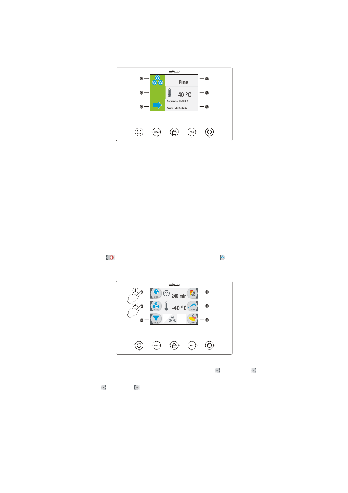
During deep freezing the device displays the temperature of the cabinet, the program name (if envisioned) and the
duration of deep freezing.
Parameter r11 establishes the work set-point during storage.
6.10 Time-controlled soft deep freezing and storage
The time-controlled soft deep freezing and storage cycle is divided into the following three phases:
- deep freezing soft phase
- deep freezing
- storage.
On conclusion of a phase, the device passes automatically to the next.
Operate as indicated to start the cycle:
1. Make sure the device is in the "on" status.
2. Make sure that the keyboard is not locked and that no procedure is in progress.
3. Press and release the key (1), and then press and release the key (2): the device will display the
duration of deep freezing and the work set-point during deep-freezing.
4.1 Press and release the MENU key and then press and release the key or the key to select the deep
freezing duration and the work set-point during deep freezing.
4.2 Press and release the key or the key to modify these values and then the ESCAPE key to memorise them;
these values can also be memorised through parameters r2 and r8.
5. Press and release the START/STOP key (1): the cycle will be started.
page 39 of 94
Page 40
EVCO S.p.A. EVFTFT818 | Installer manual ver. 2.1 | Code 144FTFT818E214
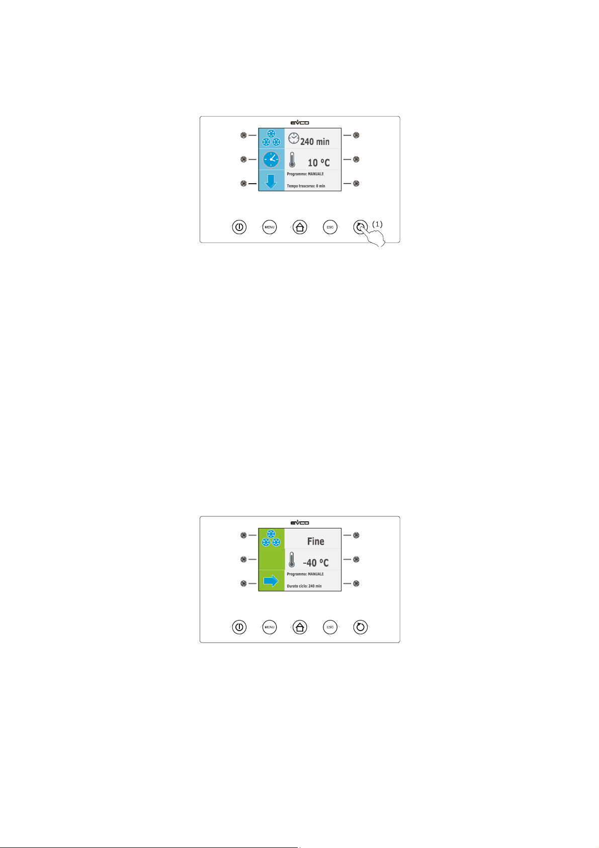
During soft deep freezing phase, the device displays the residual deep freezing time, the temperature of the cabinet,
the name of the program (if envisioned) and the time passed from the start of deep freezing.
Operate as indicated to stop the cycle:
6. Press and hold the START/STOP key 3 s.
The successive parameters establish the following values:
- parameter r7 establishes the work set-point during the deep freezing soft phase.
- parameter r14 establishes deep freezing soft phase duration.
On expiry of the soft deep freezing phase duration, the device automatically passes to deep freezing.
During deep freezing the device displays the residual deep freezing time, the temperature of the cabinet, the name of
the program (if envisioned) and the time passed from the start of deep freezing.
The successive parameters establish the following values:
- parameter r2 establishes deep freezing duration
- parameter r8 establishes the work set-point during deep freezing.
On expiry of the deep freezing duration, the device automatically passes to storage mode and the buzzer is activated
for the time period established with parameter AA.
Press and release a key to silence the buzzer.
During storage the device displays the temperature of the cabinet, the program name (if envisioned) and the duration
of deep freezing.
Parameter r11 establishes the work set-point during storage.
page 40 of 94
Page 41
EVCO S.p.A. EVFTFT818 | Installer manual ver. 2.1 | Code 144FTFT818E214
6.11 Continuous deep freezing
Operate as indicated to start the cycle:
1. Make sure the device is in the "on" status.
2. Make sure that the keyboard is not locked and that no procedure is in progress.
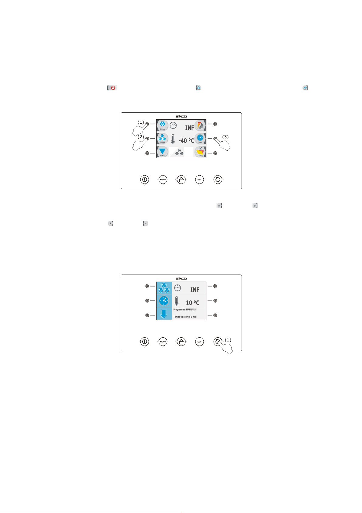
3. Press and release the key (1), press and release the key (2) and then press and release the key (3)
twice. The device will display the work set-point during deep freezing.
4.1 Press and release the MENU key and then press and release the key or the key to select the work set-
point during deep freezing.
4.2 Press and release the key or the key to modify this value and then the ESCAPE key to memorise it; this
value can also be memorised through parameter r8.
5. Press and release the START/STOP key (1): the cycle will be started.
During deep freezing the device displays the temperature of the cabinet, the program name (if envisioned) and the
time passed since the start of deep freezing.
Operate as indicated to stop the cycle:
6. Press and hold the START/STOP key 3 s.
Parameter r8 establishes the work set-point during deep freezing.
6.12 Blast chilling/deep freezing intensity
The device can manage the phase cut speed regulator for EVDFAN1 single phase fans (to be ordered separately); see
paragraph 14.4 “phase cut speed regulator for EVDFAN1 single phase fans”.
The regulator can be used to manage evaporator fan activities with a single analogue control, i.e. via the PWM
analogue output of the device and the regulator phase cut output (the digital output K3 is however activated).
Parameter F0 must be set at 3.
Parameters F18... F22 establish speed 1... 5 of the evaporator speed (intended as a percentage of the maximum
speed), parameter F23 establishes the speed at which the evaporator fan is switched on during post blast chilling
page 41 of 94
Page 42

EVCO S.p.A. EVFTFT818 | Installer manual ver. 2.1 | Code 144FTFT818E214
storage and parameter F24 establishes the speed at which the evaporator fan is switched on during post deep freezing
storage (the latter intended as one of the speeds 1... 5).
The following table illustrates the speeds at which the evaporator fan is switched on during the operating cycles.
A different speed can be selected using the procedure given in 6.12.1 (intended as one of the speeds 1.. 5) in
temporary mode (i.e. if a power cut occurs, on restore of the same the speeds illustrated in the following table will be
offered), except if the selection is made before starting a blast chilling and storage cycle or before starting a hard blast
chilling and storage cycle or before starting a soft deep freezing and storage cycle (in this case the speeds are
memorised instead).
Blast chilling
and storage
Hard blast
chilling and
storage
Deep freezing
and storage
Soft deep
freezing and
storage
Blast chilling hard phase - speed 5 - -
Blast chilling
speed 1... 5 (can
be memorised
with the
procedure given
in paragraph
6.12.1 if selected
before starting
the operating
cycle)
speed 1... 5 (can
be memorised
with the
procedure given
in paragraph
6.12.1 if selected
before starting
the operating
cycle)
- -
speed 1... 5 (can
be memorised
with the
procedure given
Deep freezing soft phase - - -
in paragraph
6.12.1 if selected
before starting
the operating
cycle)
Deep freezing - - speed 5 speed 5
Storage
speed established
with parameter
F23
speed established
with parameter
F23
speed established
with parameter
F24
speed established
with parameter
F24
page 42 of 94
Page 43
EVCO S.p.A. EVFTFT818 | Installer manual ver. 2.1 | Code 144FTFT818E214
6.12.1 Selecting the evaporator fan speed
Operate as follows:
1. Make sure the device is in the "on" status.
2. Make sure that the keyboard is not locked and that no procedure is in progress.
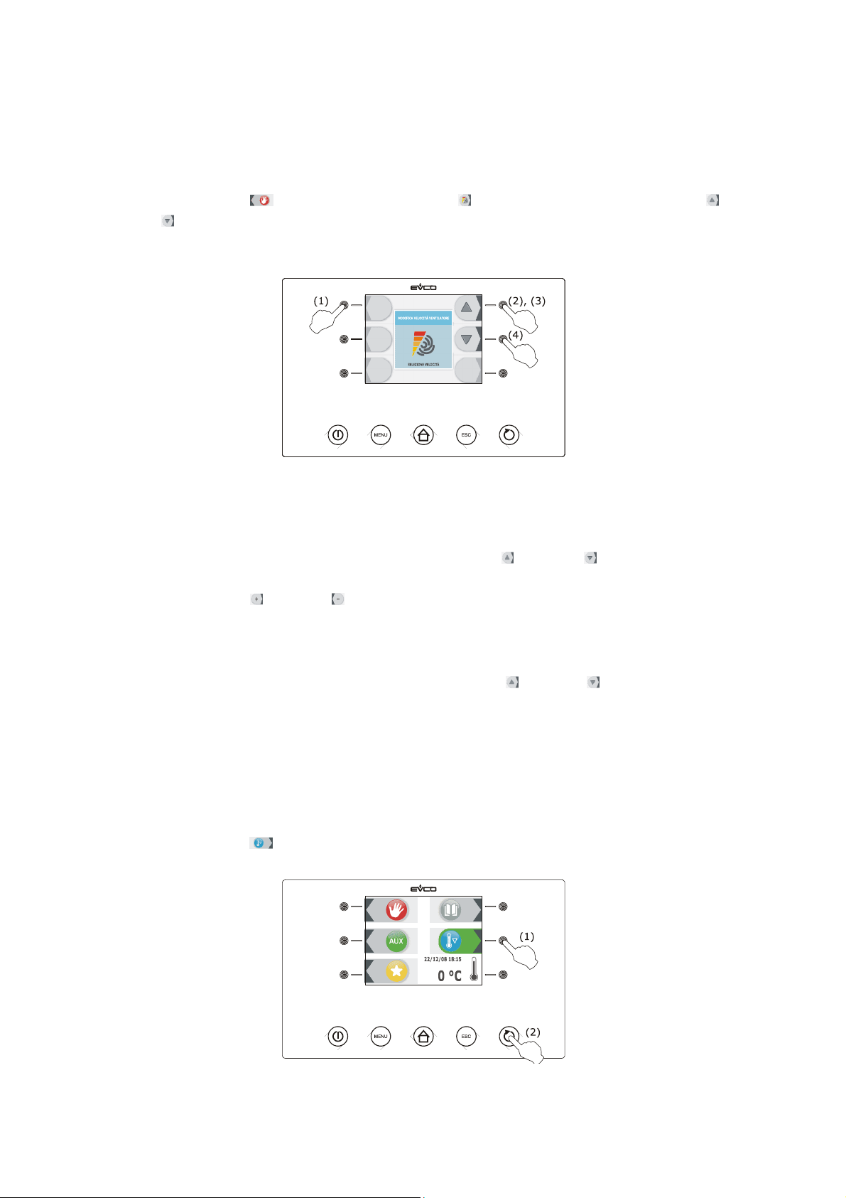
3. Press and release the key (1), press and release the key (2) and then press and release the key (3)
or the key (4). The LED bars will supply information relative to fan speed (for example, one bar corresponds
to speed 1, two bars on correspond to speed 2, three bars on correspond to speed 3, etc.).
Alternatively:
4. Make sure the device is in the "run" status.
5. Make sure that the keyboard is not locked and that no procedure is in progress.
6. Press and release the MENU key and then press and release the key or the key to select the evaporator
fan speed
7. Press and release the key or the key to modify these values and then press the ESCAPE key to memorise
it.
Operate as follows to exit the procedure:
8. Press and release the ESCAPE key or do not operate for 60 s.
The fan is switched on at the selected speed after 5 s from release of the key or the key.
6.13 Pre-cooling start-up
Every operating cycle can be preceded by pre-cooling.
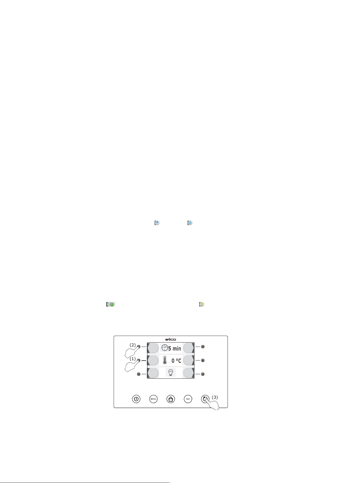
Operate as indicated to start pre-cooling:
1. Make sure the device is in the "on" status.
2. Make sure that the keyboard is not locked and that no procedure is in progress.
3. Press and release the key (1) and then press and release the START/STOP key (2).
page 43 of 94
Page 44
EVCO S.p.A. EVFTFT818 | Installer manual ver. 2.1 | Code 144FTFT818E214
Operate as indicated to cut-off pre-cooling:
4. Press and hold the START/STOP key 3 s.
Parameter r120 establishes the work set-point during pre-cooling.
When the cabinet temperature reaches that established with parameter r12, pre-cooling continues and the buzzer is
activated for 2 s.
6.14 Management of the test regarding correct insertion of
the needle probe
If the needle probe is enabled, i.e. the parameter P3 is set at values different to 0; the temperature-controlled cycles
are preceded by a test on two phases for the verification of the correct insertion of the needle probe.
The second phase is only performed if the first is not completed successfully.
The first phase is completed successfully if the "temperature detected by the needle probe - cabinet temperature"
difference is greater than the value established with parameter r17 in at least 3 controls out of 5 (the controls are
performed at 10 s intervals, consider the difference without sign).
The second phase is completed successfully if the "temperature detected by the needle probe - cabinet temperature"
difference is 1°C/1°F higher with respect to the previous control in at least 6 controls out of 8 (the controls are
performed at time intervals corresponding to 1/8 of the time established with parameter r18; consider the difference
without sign).
If the test is completed successfully, the cycle will be started; if the test is not completed successfully, the buzzer will
be activated for 5 s every 10 s and the cycle will be started with timed-control.
To start the temperature-controlled cycle, press the key or the key. After 1 min from the signal that the test has
not been completed successfully without having operated, the cycle is started with time control.
If parameter r17 is set at 0, the test will not be carried out (neither first nor second phase).
6.15 Switching on UV light for sterilisation cycle
Operate as follows:
1. Make sure that parameter u11 is set at 2.
2. Make sure the device is in the "on" status and that the door is closed, i.e. the door micro switch is not active.
3. Make sure that the keyboard is not locked and that no procedure is in progress.
4. Press and release the key (1), press and release the key (2) and then press and release the
START/STOP key (3). The device will display the residual time of the UV light switch-on duration and the
cabinet temperature.
The UV light is switched on for the time period established by parameter u6; opening the door i.e. the activation of the
door micro switch cause the light to switch off.
page 44 of 94
Page 45
EVCO S.p.A. EVFTFT818 | Installer manual ver. 2.1 | Code 144FTFT818E214
If the UV light is on, it will not be allowed to select or start any operating cycle.
6.16 Heating the needle probe
Operate as follows:
1. Make sure the device is in the "on" status or storage is in progress and that the door is open, i.e. the door
micro switch is active.
2. Make sure that the keyboard is not locked and that no procedure is in progress.
3. Press and release the key (1), press and release the key (2) and then press and release the
START/STOP key (3). The device will display the temperature detected by the needle probe and the cabinet
temperature.
Output K6 is activated at maximum for the time established with parameter u8 or until the temperature detected by
the needle probe reaches that established with parameter u7; closing the door, i.e. the deactivation of the door micro
switch input causes heating to be cut-off.
The buzzer is activated for 2 s on conclusion of heating.
6.17 Fish sanification
The fish sanification cycle is divided into the following three phases:
- blast chilling
- maintenance
- storage.
On conclusion of a phase, the device passes automatically to the next.
Operate as indicated to start the cycle:
1. Make sure the device is in the "on" status.
2. Make sure that the keyboard is not locked and that no procedure is in progress.
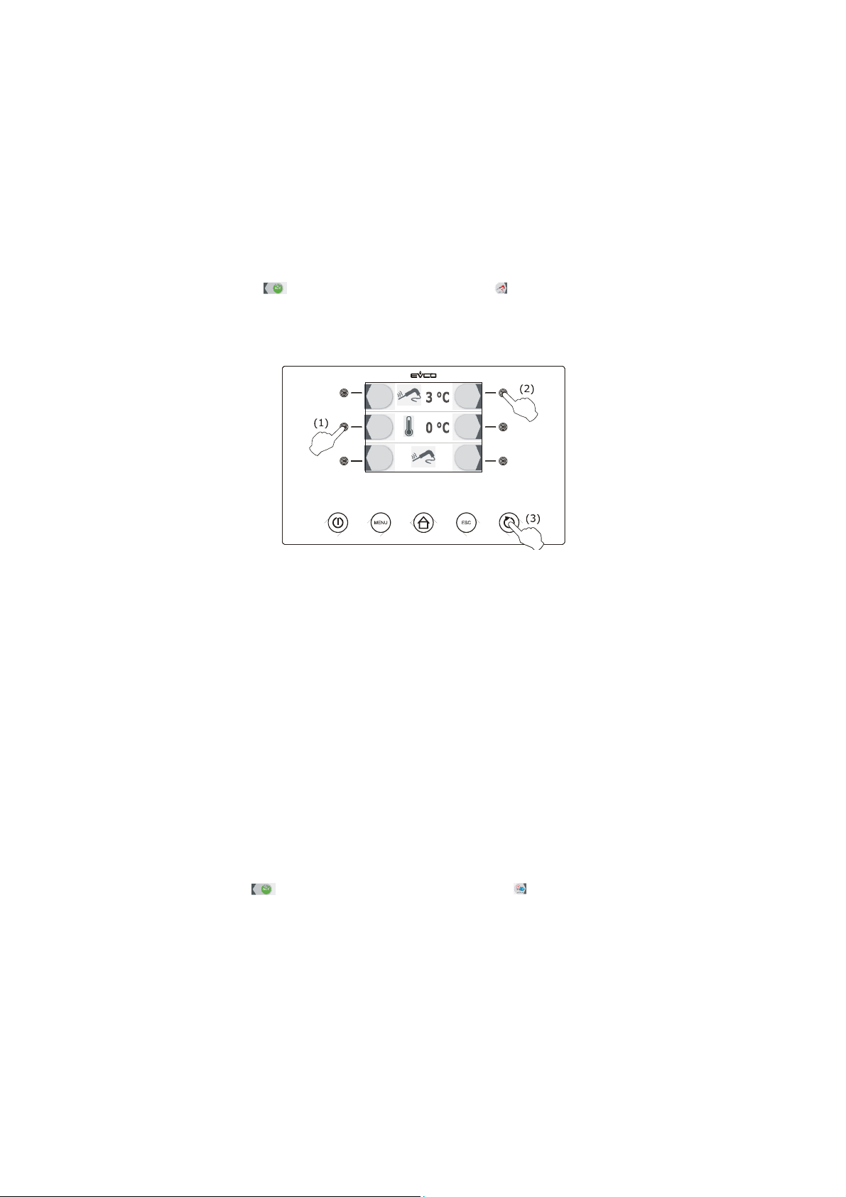
3. Press and release the key (1) and then press and release the key (2): the device will display the blast
chilling end temperature, the work set-point during blast chilling and the duration of maintenance.
page 45 of 94
Page 46
EVCO S.p.A. EVFTFT818 | Installer manual ver. 2.1 | Code 144FTFT818E214
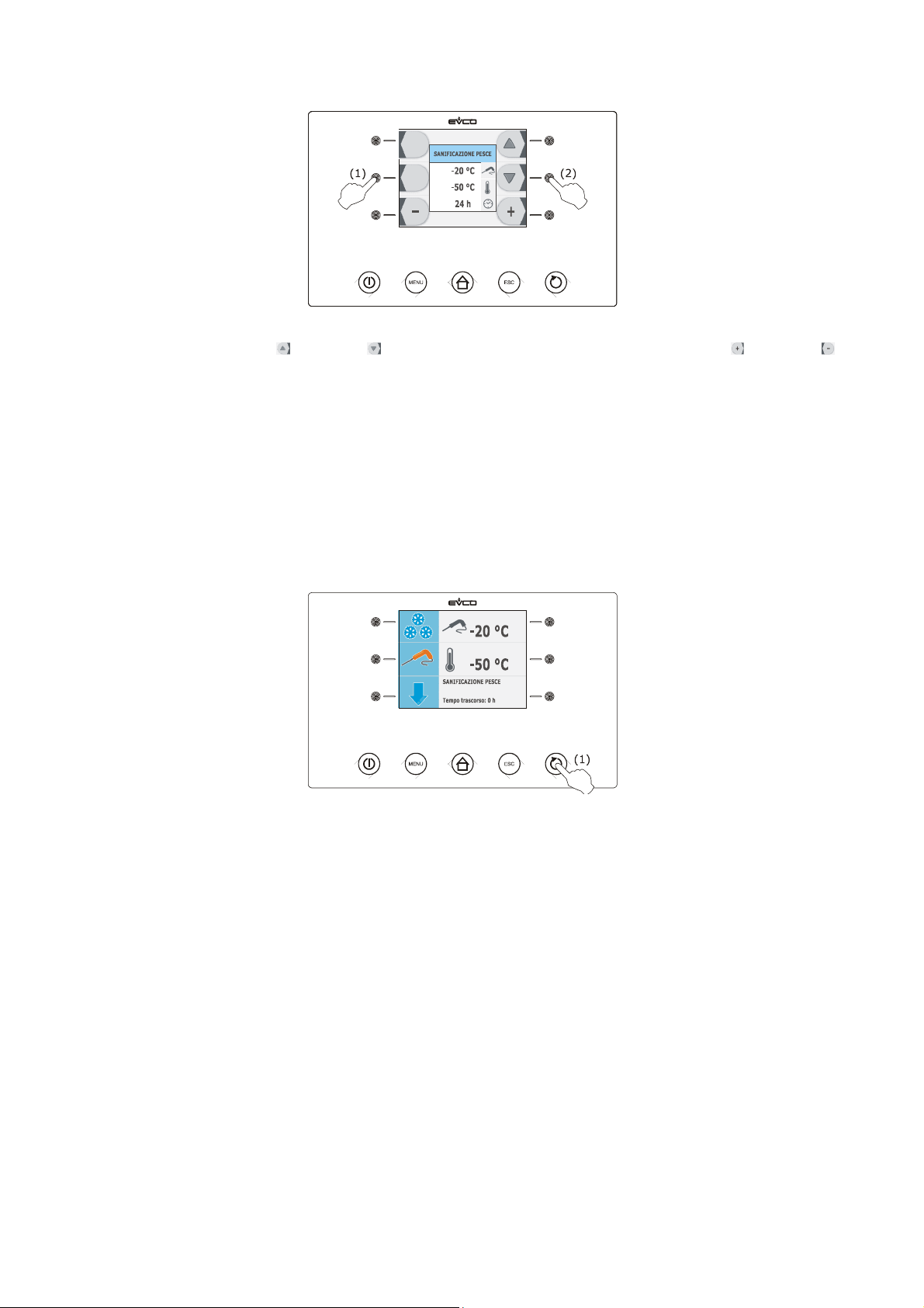
4.1 Press and release the key or the key to select these values and press and release the key or the
key to modify them.
5. Press and release the START/STOP key (1): the test to verify the correct insertion of the needle probe will be
started; see paragraph 6.14 " Test for verification of the correct insertion of the needle probe".
5.1 If the test is completed successfully, the cycle will be started.
5.2 If the test is not completed successfully, the buzzer will be activated, the device will display the
indication “ALARM San” and the cycle will be stopped.
Press and release a key to silence the buzzer.
During blast chilling the device displays the temperature detected by the needle probe, the cabinet temperature and
the time passed since the start of blast chilling.
Operate as indicated to stop the cycle:
6. Press and hold the START/STOP key 3 s.
When the temperature detected by the needle probe reaches the blast chilling end temperature, it means that blast
chilling has been completed and the device will automatically pass to maintenance.
During maintenance the the blast chilling end temperature also establishes the work set-point during maintenance.
On expiry of the duration of maintenance the device automatically passes to storage.
Parameter r11 establishes the work set-point during storage.
page 46 of 94
Page 47
EVCO S.p.A. EVFTFT818 | Installer manual ver. 2.1 | Code 144FTFT818E214
7 “PROGRAMS” FUNCTION
7.1 Foreword
The programs function can be used to memorise some settings in a program and start an operating cycle with the
settings it has memorised.
Up to 99 programs can be memorised.
7.2 Memorisation of a program
Operate as follows:
1. Make sure that the keyboard is not locked and that no procedure is in progress.
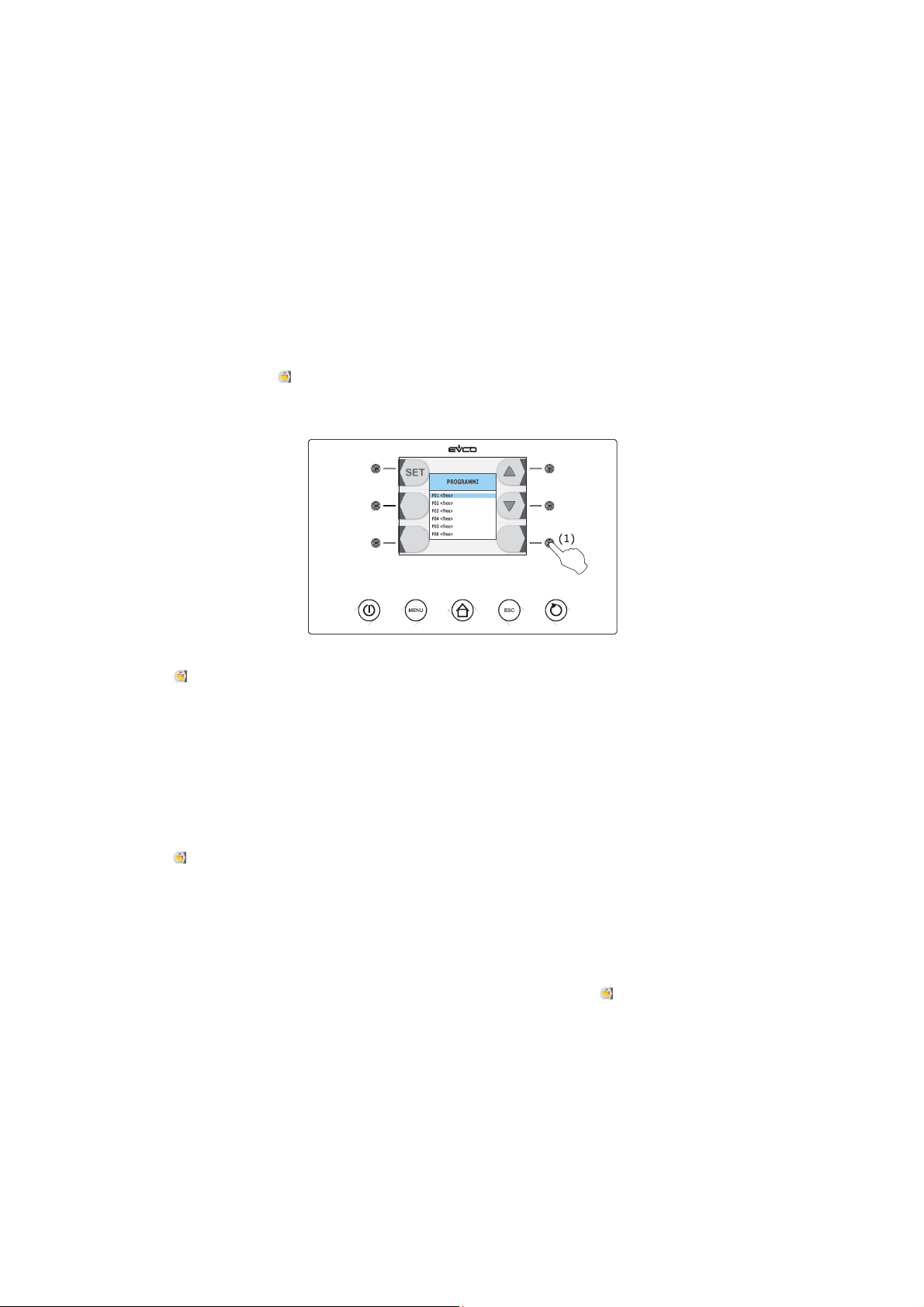
2. Press and release the key (1) before starting an operating cycle or during storage: the device will display
the number of the first program available.
2.1 If the key is pressed and released before starting an operation cycle, the device will memorise the following
settings:
- type of operating cycle selected
- blast chilling/deep freezing intensity selected
- if the key is pressed before starting-up a temperature-controlled cycle:
- the work set-point during blast chilling and the blast chilling end temperature
- if the key is pressed before starting-up a time-controlled cycle:
- the work set-point during blast chilling and the blast chilling duration.
2.2 If the key is pressed and released during storage, the device memorises the following settings:
- type of operating cycle in progress
- the duration of blast chilling or deep freezing, i.e. the time taken to successfully complete blast chilling
or deep freezing.
- blast chilling/deep freezing intensity selected before starting an operating cycle.
- the work set-point selected before starting up an operating cycle.
The execution of a program memorised by pressing and releasing the key during storage causes the
start of a timed cycle.
page 47 of 94
Page 48

EVCO S.p.A. EVFTFT818 | Installer manual ver. 2.1 | Code 144FTFT818E214
3. Press and release the key (1) or the key (2) to select the program number and then press and release
the key (3) in order to associate a name.
4. Press and release the key, the key, the key or the key to select the character and then press and
release the key to confirm it.
5. Press and release the key, the key, the key or the key to select “[END]” and then press and
release the key.
Operate as follows to abandon the procedure indicated:
6. Press and release the ESCAPE key or do not operate for 60 s.
7.3 Execution of a program
Operate as follows:
1. Make sure the device is in the "on" status.
2. Make sure that the keyboard is not locked and that no procedure is in progress.
3. Press and release the key, press and release the key or the key to select the program and then
press and release the START/STOP key to start it: the operating cycle will be started with the settings
memorised in the program.
page 48 of 94
Page 49

EVCO S.p.A. EVFTFT818 | Installer manual ver. 2.1 | Code 144FTFT818E214
8 “FAVOURITES” FUNCTION
8.1 Foreword
The favourites function can be used to execute a recently started program.
It is possible to start up to 99 recently started programs
8.2 Execution of a program
Operate as follows:
1. Make sure the device is in the "on" status.
2. Make sure that the keyboard is not locked and that no procedure is in progress.
3. Press and release the key, press and release the key or the key to select the program and then
press and release the START/STOP key to start it: the operating cycle will be started with the settings
memorised in the program.
page 49 of 94
Page 50

EVCO S.p.A. EVFTFT818 | Installer manual ver. 2.1 | Code 144FTFT818E214
9 “HACCP” FUNCTION
9.1 Foreword
Using the “HACCP” function, it is possible to memorise up to 9 events for each of the 3 HACCP alarms, after which the
most recent event overwrites the oldest.
The following table illustrates the information relative to the HACCP alarms, which the device can memorise.
Alarm Code Critical value
the maximum
temperature-controlled
blast chilling or deep
freezing not concluded
within maximum
duration alarm
maximum temperature
during storage alarm
power-cut during storage
alarm
To prevent repeated memorisation of power cut alarms (“PF” code), make sure that the device is in the "stand-by" or
"on" status before disconnecting the power supply.
If the duration of the power cut alarm (“PF” code) is such to cause a clock error (“rtc” code), the device does not
memorise the date or time the alarm occurred or its duration.
tiM
AH
PF
temperature detected by
the needle probe after
temperature-controlled
blast chilling of deep
freezing not concluded
within maximum
duration
maximum cabinet
temperature during the
alarm
the cabinet temperature
at restore f power supply
Date and time of
occurrence
yes
yes
yes
Duration
from 1 min to 99 h and
59 min, partial if the
alarm is in progress
from 1 min to 99 h and
59 min, partial if the
alarm is in progress
from 1 min to 99 h and
59 min
9.2 Display of information relative to the HACCP alarms
Operate as follows:
1. Make sure the device is in the "on" status.
2. Make sure that the keyboard is not locked and that no procedure is in progress.
page 50 of 94
Page 51
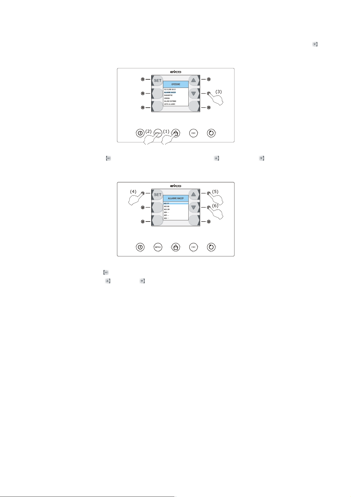
EVCO S.p.A. EVFTFT818 | Installer manual ver. 2.1 | Code 144FTFT818E214
3. Press and release the HOME key (1), press and release the MENU key (2) and then press and release the
key (3) in order to select the “HACCP ALARMS”.
4. Press and release the key (4) and then press and release the key (5) or the key (6) to select the
alarm (the greater the number that follows the alarm code, the older the alarm).
5. Press and release the key: the device will display the information relative to the alarm.
6. Press and release the key or the key to display the information of the previous alarm or the successive
alarm.
Operate as follows to exit the procedure:
7. Press and release the ESCAPE key or do not operate for 60 s.
9.3 Deleting the information relative to the HACCP
alarms
Operate as follows:
1. Make sure the device is in the "on" status.
2. Make sure that the keyboard is not locked and that no procedure is in progress.
page 51 of 94
Page 52
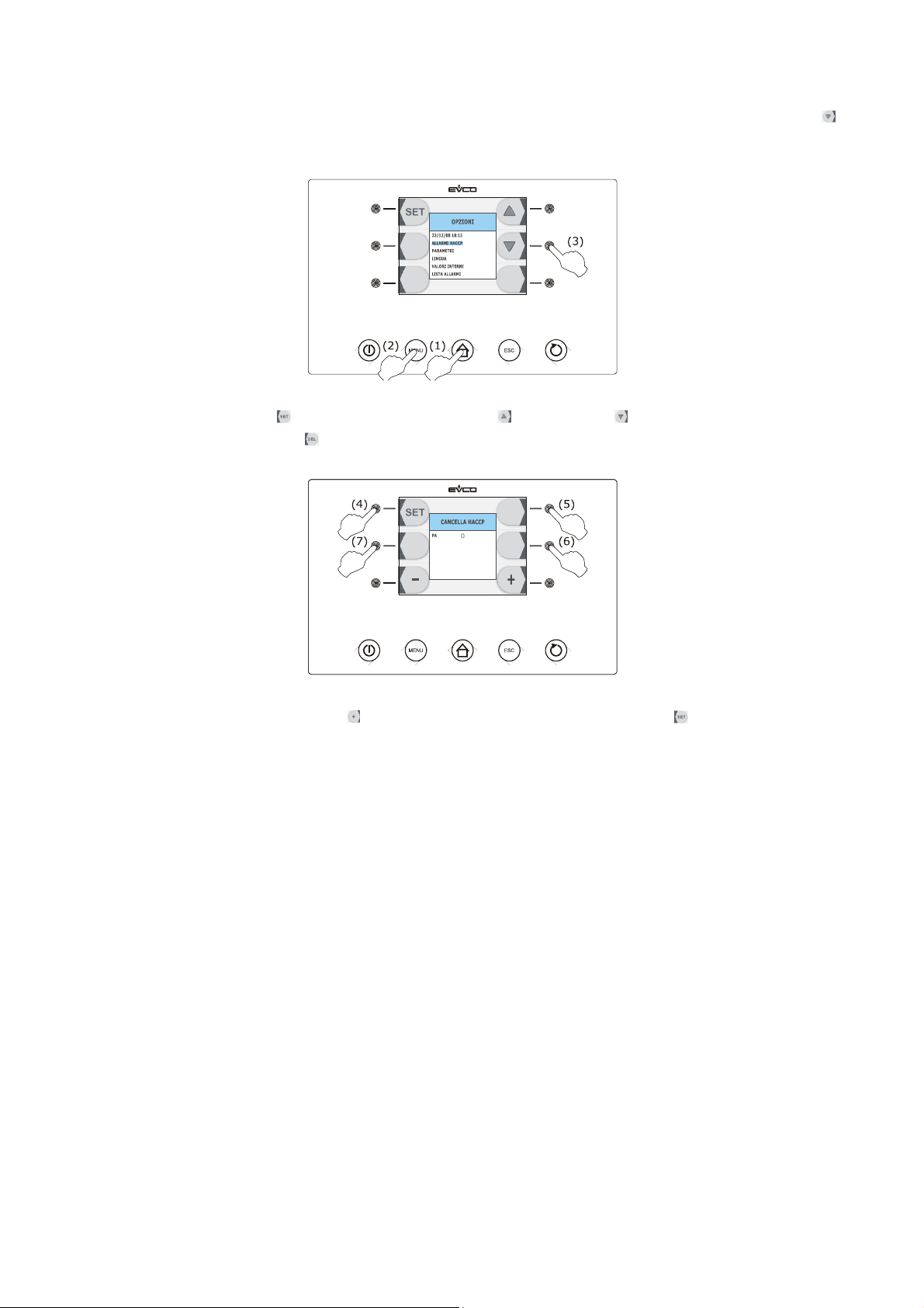
EVCO S.p.A. EVFTFT818 | Installer manual ver. 2.1 | Code 144FTFT818E214
3. Press and release the HOME key (1), press and release the MENU key (2) and then press and release the
key (3) in order to select the “HACCP ALARMS”.
4. Press and release the key (4), press and release the key (5) or the key (6) to select the alarm and
then press and release the key (7).
5. Repeatedly press and release the key to set “149” and then press and release the key.
Operate as follows to exit the procedure:
6. Press and release the ESCAPE key or do not operate for 60 s.
page 52 of 94
Page 53
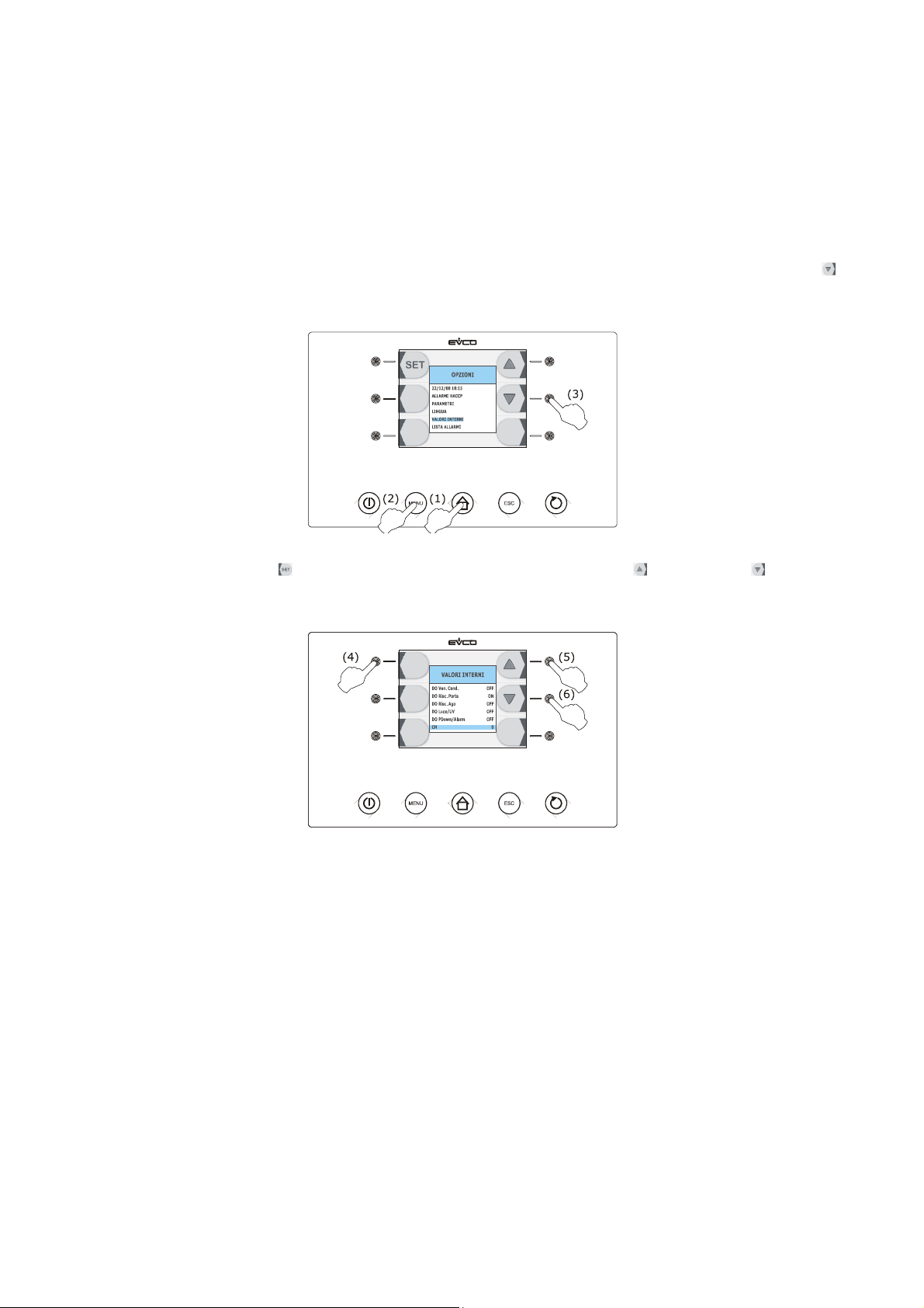
EVCO S.p.A. EVFTFT818 | Installer manual ver. 2.1 | Code 144FTFT818E214
10 COMPRESSOR OPERATING HOURS COUNT
10.1 Display of compressor operating hours
Operate as follows:
1. Make sure that the instrument is in the “on” status.
2. Make sure that the keyboard is not locked and that no procedure is in progress.
3. Press and release the HOME key (1), press and release the MENU key (2) and then press and release the
key repeatedly (3) in order to select the “INTERNAL VALUES”.
4. Press and release the key (4) and then repeatedly press and release the key (5) or the key (6) to
select “CH”.
Operate as follows to exit the procedure:
5. Press and release the ESCAPE key or do not operate for 60 s.
To delete the compressor operating hours, see paragraph 10.3 "Restoring the factory settings".
page 53 of 94
Page 54
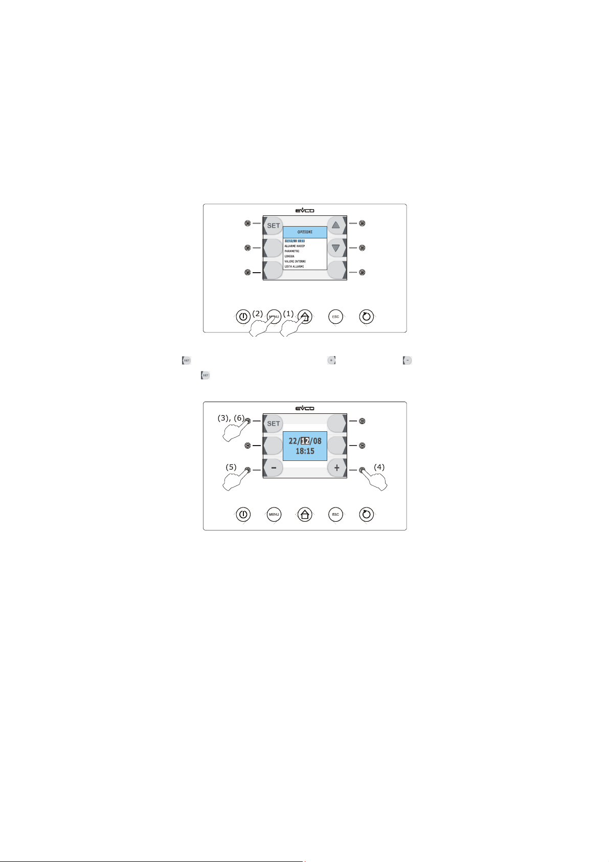
EVCO S.p.A. EVFTFT818 | Installer manual ver. 2.1 | Code 144FTFT818E214
11 CONFIGURATION
11.1 Setting the real date and time
Operate as follows:
1. Make sure that the instrument is in the “on” status.
2. Make sure that the keyboard is not locked and that no procedure is in progress.
3. Press and release the HOME key (1) and then press and release the MENU key (2).
4. Press and release the key (3), press and release the key (4) or the key (5) to modify the value and
then press and release the key (6) again to confirm and select the next one.
Operate as follows to exit the procedure:
5. Press and release the ESCAPE key or do not operate for 60 s.
11.2 Setting the configuration parameters
Operate as follows:
1. Make sure that the instrument is in the “on” status.
2. Make sure that the keyboard is not locked and that no procedure is in progress.
page 54 of 94
Page 55
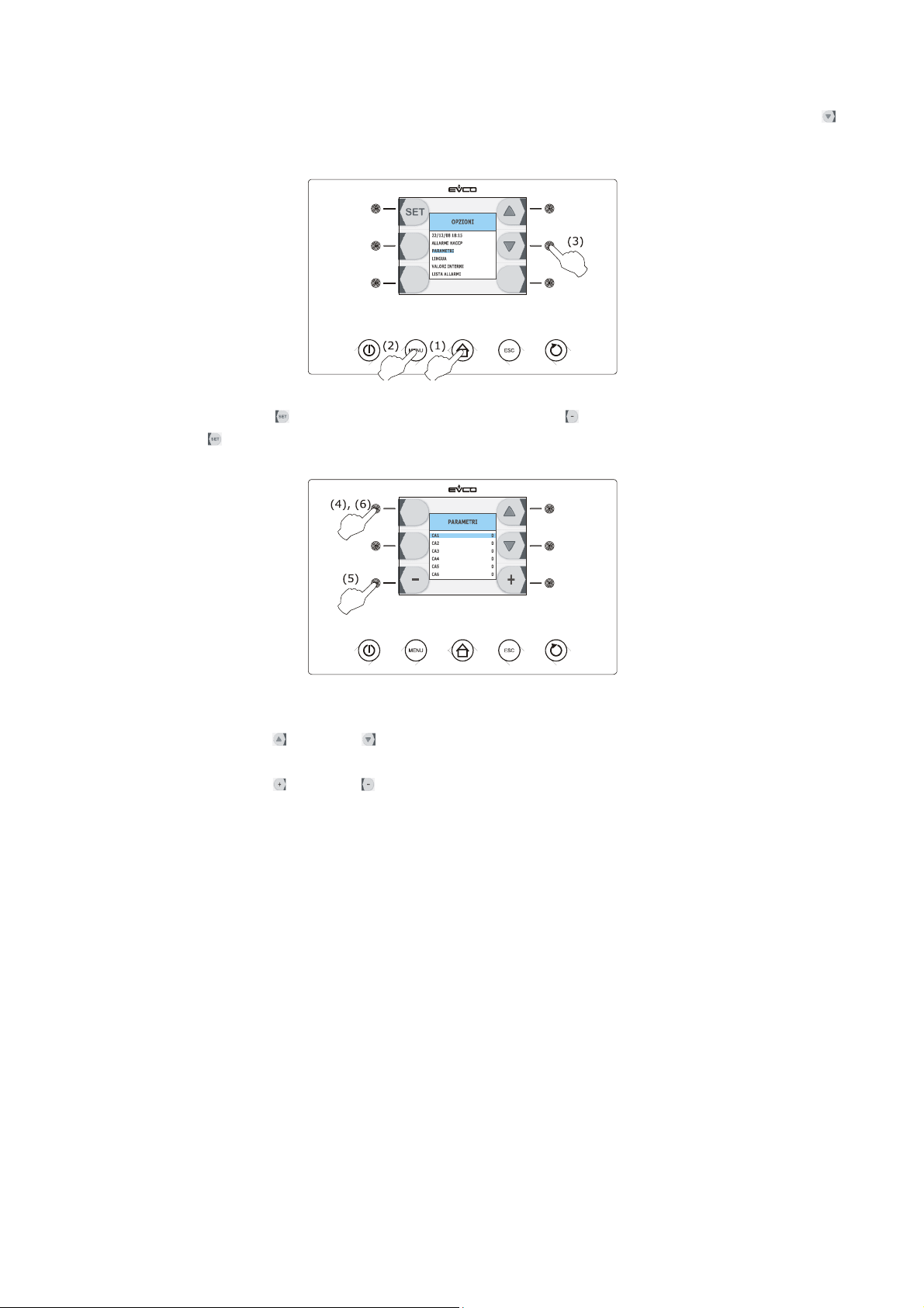
EVCO S.p.A. EVFTFT818 | Installer manual ver. 2.1 | Code 144FTFT818E214
3. Press and release the HOME key (1), press and release the MENU key (2) and then press and release the
key repeatedly (3) in order to select the “PARAMETERS”.
4. Press and release the key (4), repeatedly press and release the key (5) to set “-19”and then press and
release the key (6) again.
Operate as follows to select a parameter:
5. Press and release the key or the key.
Operate as follows to set a parameter:
6. Press and release the key or the key.
Operate as follows to exit the procedure:
7. Press and release the ESCAPE key or do not operate for 60 s.
Cut the device power supply off after setting the configuration parameters.
11.3 Restoring the factory settings
11.3.1 Access to the procedure
Operate as follows:
1. Make sure that the instrument is in the “stand-by” status.
2. Make sure that the keyboard is not locked and that no procedure is in progress.
page 55 of 94
Page 56
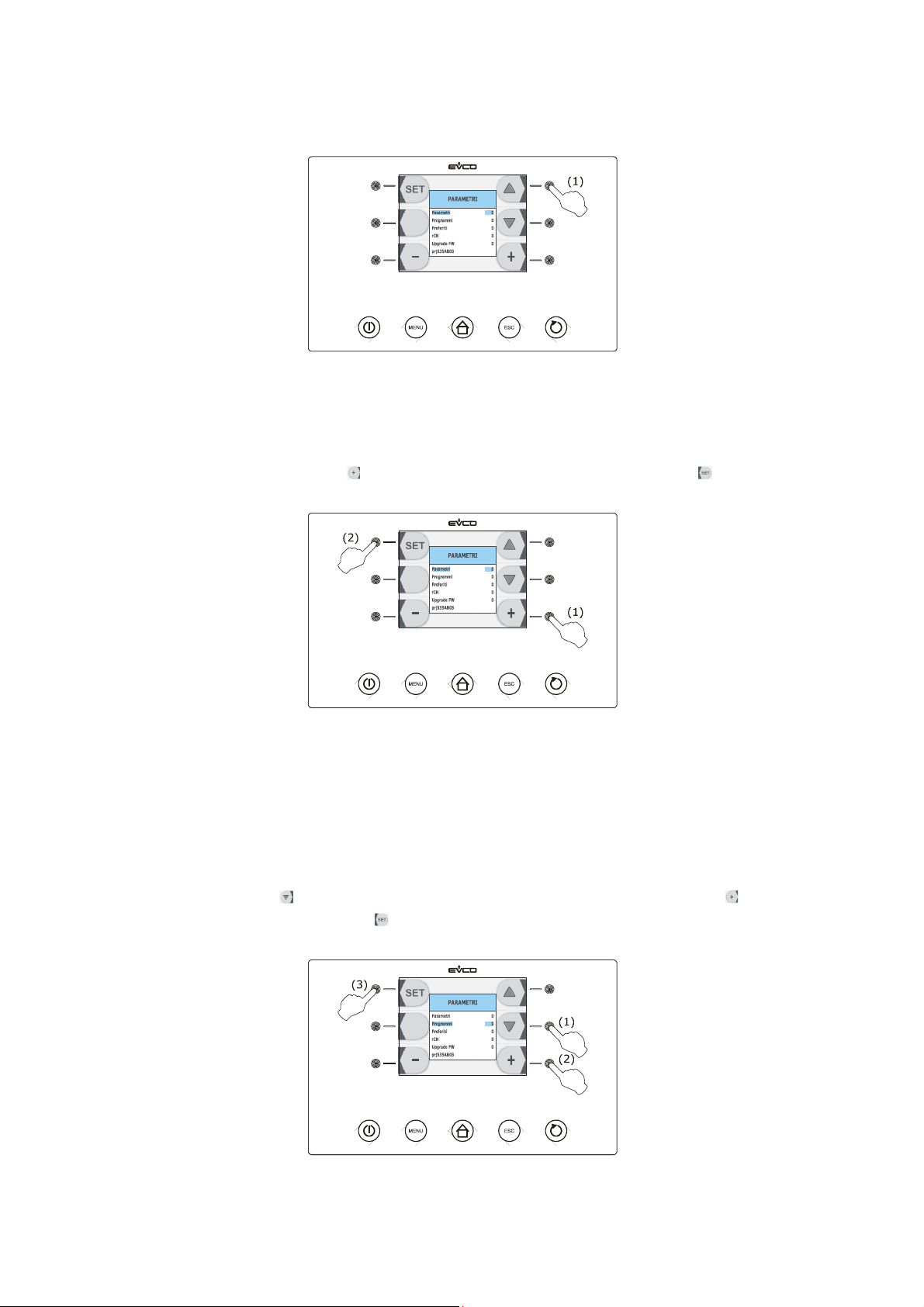
EVCO S.p.A. EVFTFT818 | Installer manual ver. 2.1 | Code 144FTFT818E214
3. Press and release the highest interactive key on the right (1).
11.3.2 Restoring the configuration parameters
Operate as follows:
1. Access to the; see paragraph 10.3.1 “Access to the procedure”.
2. Repeatedly press and release the key (1) to set “149” and then press and release the key (2).
Operate as follows to exit the procedure:
3. Press and release the ESCAPE key or do not operate for 60 s.
11.3.3 Deleting programs
Operate as follows:
1. Access to the; see paragraph 10.3.1 “Access to the procedure”.
2. Press and release the key (1) to select “Programs”, repeatedly press and release the key (2) to set
“149” and then press and release the key (3).
page 56 of 94
Page 57
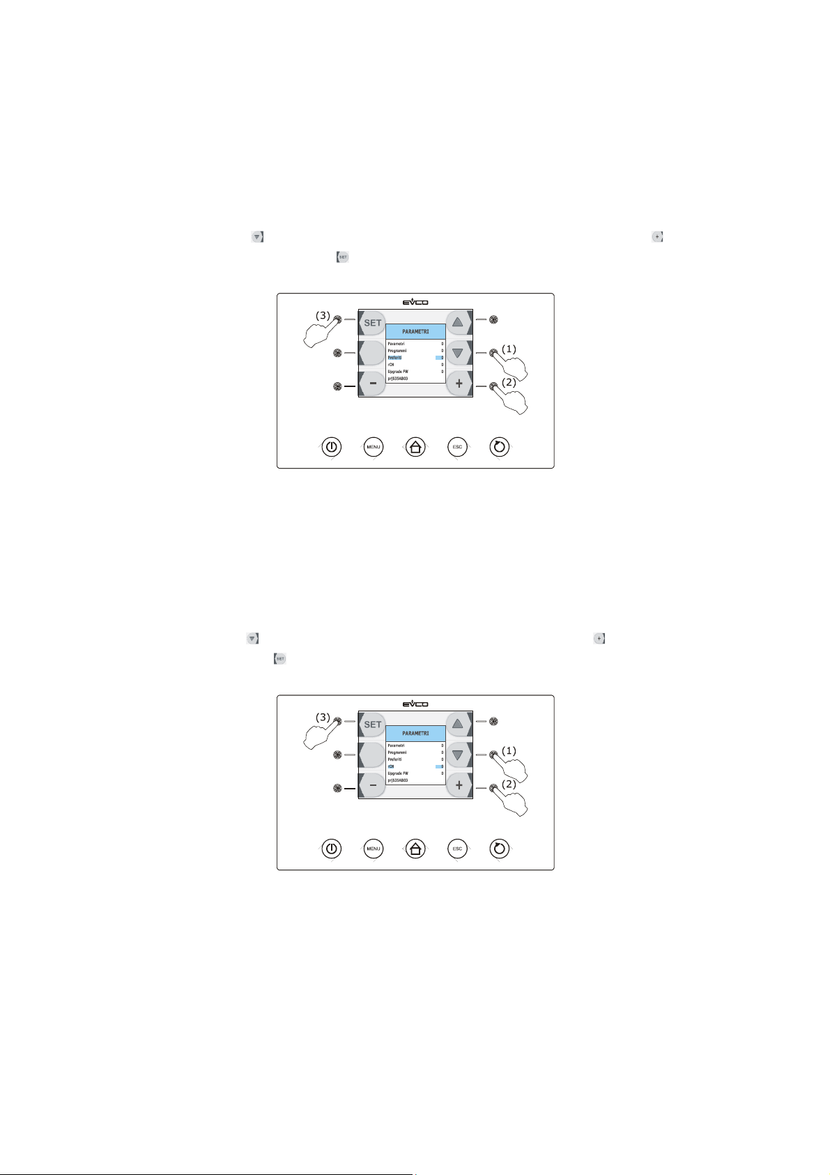
EVCO S.p.A. EVFTFT818 | Installer manual ver. 2.1 | Code 144FTFT818E214
Operate as follows to exit the procedure:
3. Press and release the ESCAPE key or do not operate for 60 s.
11.3.4 Deleting favourites
Operate as follows:
1. Access to the; see paragraph 10.3.1 “Access to the procedure”.
2. Press and release the key (1) to select “Programs”, repeatedly press and release the key (2) to set
“149” and then press and release the key (3).
Operate as follows to exit the procedure:
3. Press and release the ESCAPE key or do not operate for 60 s.
11.3.5 Deleting the compressor operating hours
Operate as follows:
1. Access to the; see paragraph 10.3.1 “Access to the procedure”.
2. Press and release the key (1) to select “rCH”, repeatedly press and release the key (2) to set “149” and
then press and release the key (3).
Operate as follows to exit the procedure:
3. Press and release the ESCAPE key or do not operate for 60 s.
page 57 of 94
Page 58

EVCO S.p.A. EVFTFT818 | Installer manual ver. 2.1 | Code 144FTFT818E214
11.4 List of configuration parameters
The following table illustrates the meaning of the configuration parameters.
The management of some inputs and outputs is subject to the value set with some parameters, as follows:
- management of the needle probe is only available if parameter P3 is set at values different to 0
- management of the evaporator probe is only available if the parameter P4 is set at 1
- management of the condenser probe is only available if the parameter P5 is set at 1
- management of the cabinet light is only available if the parameter u11 is set at 0
- management of the UV light is only available if parameter u11 is set at 1.
- management of the pump down valve is only available if parameter u1 is set at 0
- management of the alarm output is only available if parameter u1 is set at 1.
The evaporator fan control signal can be analogue (parameter F0 set at 3) or digital (parameter F0 set at values
different to 3).
Par. Min. Max. Unit Default Analogue inputs
CA1 -25 25 °C/°F (1) 0 cabinet probe offset
CA2 -25 25 °C/°F (1) 0 needle probe offset 1
CA3 -25 25 °C/°F (1) 0 evaporator probe offset
CA4 -25 25 °C/°F (1) 0 condenser probe offset
CA5 -25 25 °C/°F (1) 0 needle probe offset 2
CA6 -25 25 °C/°F (1) 0 needle probe offset 3
probe type
P0 0 1 - - - - 0
P2 0 1 - - - - 0
P3 0 3 - - - - 1
0 = PTC
1 = NTC
temperature unit of measurement (2)
0 = °C
1 = °F
number of needle probe sensors
0 = needle probe not available
1 = 1 (needle probe 1)
2 = 2 (needle probe 1 and needle probe 2)
3 = 3 (needle probe 1, needle probe 2 and needle probe
3)
P4 0 1 - - - - 1
P5 0 1 - - - - 1
enabling the evaporator probe
1 = yes
enabling the condenser probe
1 = yes
page 58 of 94
Page 59

EVCO S.p.A. EVFTFT818 | Installer manual ver. 2.1 | Code 144FTFT818E214
orientation of the visualization
P8 0 1 - - - - 1
0 = device located at the top as to the unit
1 = device located at the bottom as to the unit
Par. Min. Max. Unit Default Main regulator
r0 1 15 °C/°F (1) 2 parameters differential r7, r8, r9, r10, r11 and r12
r1 1 500 min 90 duration of time-controlled blast chilling
r2 1 500 min 240 duration of time-controlled deep freezing
temperature-controlled blast chilling end time temperature;
r3 -99 99 °C/°F (1) 3
also end temperature of the temperature-controlled soft
deep freezing phase (temperature detected by the needle
probe); see also parameter r5
temperature-controlled deep freezing end temperature
r4 -99 99 °C/°F (1) -18
(temperature detected by the needle probe); see also
parameter r6
r5 1 500 min 90
r6 1 500 min 240
r7 -99 99 °C/°F (1) 0
r8 -99 99 °C/°F (1) -40
r9 -99 99 °C/°F (1) -20
r10 -99 99 °C/°F (1) 2
maximum duration of temperature-controlled blast chilling;
see parameter r3 also
maximum duration of temperature-controlled deep
freezing; see parameter r4 also
work set-point during blast chilling; also work set-point
during the soft deep freezing phase (cabinet temperature);
see also parameter r0
work set-point during deep freezing (cabinet temperature);
see also parameter r0
work set-point during hard blast chilling phase (cabinet
temperature); see also parameter r0
work set-point during post blast chilling storage (cabinet
temperature); see also parameter r0
r11 -99 99 °C/°F (1) -20
r12 -99 99 °C/°F (1) 5
work set-point during post deep freezing storage (cabinet
temperature); see also parameter r0
work set-point during pre-cooling (cabinet temperature);
see also parameter r0
page 59 of 94
Page 60

EVCO S.p.A. EVFTFT818 | Installer manual ver. 2.1 | Code 144FTFT818E214
r13 -99 99 °C/°F (1) 15
r14 10 100 % 60
r15 -99 199 °C/°F (1) 65
r16 0 2 - - - - 1
r17 0 99 °C/°F (1) 5
end temperature of the temperature-controlled hard blast
chilling phase (temperature detected by the needle probe)
duration of the time-controlled hard blast chilling phase
(intended as a percentage of the value established with
parameter r1); also duration of the time-controlled soft
deep freezing phase (intended as a percentage of the value
established with parameter r2)
temperature below which the count of the maximum
temperature-controlled blast chilling and maximum
temperature-controlled deep freezing is started
(temperature detected by the needle probe)
type of operating cycle that can be selected
0 = blast chilling and storage
1 = blast chilling and storage or deep freezing and
storage
2 = deep freezing and storage
"temperature detected by the needle probe - cabinet
temperature" minimum difference such to consider the first
phase of the test to verify correct insertion of the needle
probe completed successfully (consider the difference
without sign)
0 = the test will not be performed (neither first or second
phase)
r18 1 99 s 60
duration of the second phase of the test for verification of
correct insertion of the needle probe
r19 - - - - - - - - - - - - - - - - reserved
Par. Min. Max. Unit Default Compressor protections
minimum time between restoring the power supply after a
C0 0 240 min 0
power cut, occurring during an operating cycle and
compressor switch-on
C1 0 240 min 5
C2 0 240 min 3
minimum time between two consecutive compressor switch-
ons (3)
minimum time between compressor switch-off and
successive switch-on (3)
C3 0 240 s 0 compressor switch-on minimum duration
page 60 of 94
Page 61

EVCO S.p.A. EVFTFT818 | Installer manual ver. 2.1 | Code 144FTFT818E214
duration of compressor switch-off during the cabinet probe
C4 0 240 min 10
error (“Pr1” code) that occurs during storage; see also
parameters C5 and C9
duration of compressor switch-on during the cabinet probe
C5 0 240 min 10
error (“Pr1” code) that occurs during post blast chilling
storage; see also parameter C4
C6 0 199 °C/°F (1) 80
C7 0 199 °C/°F (1) 90
condenser temperature above which the blocked
overheated condenser alarm is activated (“COH” code)
condenser temperature above which the blocked
compressor alarm is activated (“CSd” code)
C8 0 15 min 1 blocked compressor alarm delay (“CSd” code) (5)
duration of compressor switch-on during the cabinet probe
C9 0 240 min 30
error (“Pr1” code) that occurs during post deep freezing
storage; see also parameter C4
Par. Min. Max. Unit Default Defrosting (6)
d0 0 99 h 8
defrosting interval (7)
0 = defrosting will never be activated at intervals
type of defrosting
0 = electrical (the compressor will be switched off during
defrosting, the defrosting output will be activated
and the evaporator fan will be switched off)
1 = hot gas (the compressor will be switched on during
defrosting, the defrosting output will be activated
and the evaporator fan will be switched off)
2 = air (the compressor will be switched off during
defrosting and the defrosting output will be
d1 0 3 - - - - 1
activated; the evaporator fan will be switched on,
independently from the conditions of the door, i.e.
independently from the door micro switch input
status)
3 = air with door open (the compressor will be switched
off during defrosting and the defrosting output will
be activated; the evaporator fan will be switched on,
on condition that the door is open, i.e. that is on
condition that the door micro switch is active and
that the parameter i0 is set at values different to 0)
page 61 of 94
Page 62

EVCO S.p.A. EVFTFT818 | Installer manual ver. 2.1 | Code 144FTFT818E214
d2 -99 99 °C/°F (1) 2
d3 0 99 min 30
d4 0 1 - - - - 0
d5 0 99 min 30
d7 0 15 min 2
defrosting end temperature (evaporator temperature); see
also parameter d3
if parameter P4 is set at 0, duration of defrosting
if parameter P4 is s et at 1, maximum duration of
defrosting; see also parameter d2
0 = defrosting will never be activated
defrosting on start-up of blast chilling and deep freezing
1 = yes
defrosting delay on start-up of storing
0 = defrosting will be started on expiry of the time
established with parameter d0
dripping duration (the compressor and the evaporator fan
remain off during dripping and the defrosting output will be
deactivated)
minimum duration of compressor switch-on on activation of
d15 0 99 min 0
defrosting so these can be activated (only if parameter d1 is
set at 1) (8)
duration of pre-dripping (only if parameter d1 is set at 1;
d16 0 99 min 0
the compressor and evaporator fan will be off during pre-
dripping and the defrosting output will remain activated)
Par. Min. Max. Unit Default Temperature alarms (9) (10)
cabinet temperature below which the minimum temperature
alarm is activated (relative to the work set-point, i.e. “r10
A1 0 99 °C/°F (1) 10
A1” during post blast chilling storage and “r11 - A1” during
post deep freezing storage; (“AL” code); see also
parameter A11 (4)
A2 0 1 - - - - 1
enabling of minimum temperature alarm (“AL” code)
1 = yes
page 62 of 94
Page 63

EVCO S.p.A. EVFTFT818 | Installer manual ver. 2.1 | Code 144FTFT818E214
cabinet temperature above which the maximum
temperature alarm is activated (relative to the work set-
A4 0 99 °C/°F (1) 10
point, i.e. “r10 +A4” during post blast chilling storage and
“r11 +A4” during post deep freezing storage; (“AH” code);
see also parameter A11 (4)
A5 0 1 - - - - 1
enabling of maximum temperature alarm (“AH” code)
1 = yes
A7 0 240 min 15 temperature alarm delay(“AL” code and “AH” code)
A8 0 240 min 15
maximum temperature alarm delay (“AH” code) from the
conclusion of evaporator fan stop and storage start-up
duration of a power cut such to cause the power cut alarm
A10 0 240 min 5
to be memorised ( “PF” code)when the power is supplied
0 = the alarm will not be signalled
AA 0 240 s 5
duration of buzzer activation on conclusion of blast chilling
and deep freezing
A11 1 15 °C/°F (1) 2 parameters A1 and A4 differential
memorisation of the temperature-controlled blast chilling or
A13 0 1 - - - - 1
temperature-controlled deep freezing non concluded within
maximum duration alarm (“tiM” code)
1 = yes
A14 - - - - - - - - - - - - - - - - riservato
Par. Min. Max. Unit Default Evaporator and condenser fan
page 63 of 94
Page 64

EVCO S.p.A. EVFTFT818 | Installer manual ver. 2.1 | Code 144FTFT818E214
evaporator fan activity during pre-cooling, blast chilling and
deep freezing (if the parameter is set at 3, there will be
effect also during storage)
0 = off, with digital control signal, i.e. via digital output
K3
1 = on, with digital control signal, i.e. via the K3 digital
output; see also parameters F16 and F17
F0 0 3 - - - - 1
2 = parallel to the compressor, with digital control signal,
i.e. via the K3 digital output; see also parameters F9
and F17
3 = with analogue control signal, i.e. via the PWM
analogue output and the speed regulator phase cut
output for EVDFAN1 single phase fans
(to order separately); see also parameters F18,
F19, F20, F21, F22, F23 and F24
evaporator temperature above which the evaporator fan is
F1 -99 99 °C/°F (1) -1
off during storage (only if parameter F0 and/or parameter
F2 is set at 3); see also parameter F8 (11)
evaporator fan activity during storage (only if parameter F0
is set at values different to 3)
F2 0 3 - - - - 3
0 = off
1 = on
2 = parallel to the compressor; see also parameter F9
3 = on; see also parameter F1
duration of evaporator fan standstill (the compressor can be
F3 0 15 min 2
on during evaporator fan standstill, the defrosting output
will remain deactivated and the evaporator fan will remain
off)
F8 1 15 °C/°F (1) 2 F1, F16 and F17 parameters differential
F9 0 240 s 0
evaporator fan switch-off delay from compressor switch off
(only if parameter F0 and/or parameter F2 are set at 2)
condenser temperature above which the condenser fan is
F11 0 99 °C/°F (1) 15
switched on (intended as “F11 + differential and on
condition the compressor is switched off); see also
parameter F12 (4) (12)
page 64 of 94
Page 65

EVCO S.p.A. EVFTFT818 | Installer manual ver. 2.1 | Code 144FTFT818E214
F12 0 240 s 30
F15 0 240 s 15
F16 -99 99 °C/°F (1) 20
F17 -99 199 °C/°F (1) 90
F18 0 100 % 20
condenser fan switch-off delay from compressor switch-off
(only if parameter P5 is set at 0)
evaporator fan delay from door closure, i.e. from the
deactivation of the door micro switch input
evaporator temperature above which the evaporator fan is
off during pre-cooling, blast chilling and deep freezing (only
if parameter F0 is set at 1); see also parameter F8 (11)
cabinet temperature above which the evaporator fan is off
during pre-cooling, blast chilling and deep freezing (only if
parameter F0 is set at 1 or 2); see also parameter F8
evaporator fan speed 1 (intended as a percentage of the
maximum speed; sonly if parameter F0 is set at 3); see
paragraph 6.12 “Blast chilling/deep freezing intensity”
F19 0 100 % 40
F20 0 100 % 60
F21 0 100 % 80
F22 0 100 % 100
evaporator fan speed 2 (intended as a percentage of the
maximum speed; sonly if parameter F0 is set at 3); see
paragraph 6.12 “Blast chilling/deep freezing intensity”
evaporator fan speed 3 (intended as a percentage of the
maximum speed; sonly if parameter F0 is set at 3); see
paragraph 6.12 “Blast chilling/deep freezing intensity”
evaporator fan speed 4 (intended as a percentage of the
maximum speed; sonly if parameter F0 is set at 3); see
paragraph 6.12 “Blast chilling/deep freezing intensity”
evaporator fan speed 5 (intended as a percentage of the
maximum speed; sonly if parameter F0 is set at 3); see
paragraph 6.12 “Blast chilling/deep freezing intensity”
page 65 of 94
Page 66

EVCO S.p.A. EVFTFT818 | Installer manual ver. 2.1 | Code 144FTFT818E214
speed at which the evaporator fan is switched on during
post blast chilling
1 = speed established with parameter F18 (speed 1)
F23 1 5 - - - - 5
2 = speed established with parameter F19 (speed 2)
3 = speed established with parameter F20 (speed 3)
4 = speed established with parameter F21 (speed 1)
5 = speed established with parameter F22 (speed 5)
speed at which the evaporator fan is switched on during
post deep freezing
1 = speed established with parameter F18 (speed 1)
F24 1 5 - - - - 5
2 = speed established with parameter F19 (speed 2)
3 = speed established with parameter F20 (speed 3)
4 = speed established with parameter F21 (speed 1)
5 = speed established with parameter F22 (speed 5)
evaporator fan switch-on delay from compressor switch-on
F25 0 30 min 0
on start-up of blast chilling and at the start-up of deep
freezing
Par. Min. Max. Unit Default Digital inputs
effect caused by opening the door, i.e. by activation of the
door micro switch (13)
0 = no effect
1 = the compressor and the evaporator fan will be off
and the cabinet light will be on. On expiry of the
time established with parameter i2, the 3 digit
i0 0 2 - - - - 2
display will show the flashing “id” code and the
buzzer will be activated (until the door is closed);
see also parameter F15 (14)
2 = the evaporator fan will be off and the cabinet light
will be on. On expiry of the time established with
parameter i2, the 3 digit display will show the
flashing “id” code and the buzzer will be activated
(until the door is closed); see also parameter F15
type of door micro switch input contact
i1 0 1 - - - - 0
0 = normally open (input active with closed contact)
1 = normally closed (input active with open contact)
page 66 of 94
Page 67

EVCO S.p.A. EVFTFT818 | Installer manual ver. 2.1 | Code 144FTFT818E214
door open alarm signalling delay (“id” code); on expiry of
i2 -1 120 min 5
the time established with the parameter, the compressor
and the evaporator fan will be off
-1 = the alarm will not be signalled
effect caused by the activation of the high pressure input
0 = no effect
1 = the compressor and the evaporator fan will be off
i5 0 1 - - - - 1
and the condenser fan will be on. On expiry of the
time established with parameter i7, the 3 digit
display will show the flashing “HP” code and the
buzzer will be activated (until the input is
deactivated)
type of high pressure input 1
i6 0 1 - - - - 0
0 = normally open (input active with closed contact)
1 = normally closed (input active with open contact)
i7 -1 240 s 5
high pressure alarm signalling delay (“HP” code)
-1 = the alarm will not be signalled
type of low pressure input 1
i8 0 1 - - - - 0
0 = normally open (input active with closed contact)
1 = normally closed (input active with open contact)
i9 -1 240 s 5
low pressure alarm signalling delay (“LP” code)
-1 = the alarm will not be signalled
type of compressor circuit breaker protection input contact
i10 0 1 - - - - 0
0 = normally open (input active with closed contact)
1 = normally closed (input active with open contact)
i11 - - - - - - - - - - - - - - - - reserved
Par. Min. Max. Unit Default Digital outputs
utility managed by the output K8 (15)
u1 0 1 - - - - 0
0 = pump down valve (in this case, parameter u12 will
have meaning)
1 = alarm output
page 67 of 94
Page 68

EVCO S.p.A. EVFTFT818 | Installer manual ver. 2.1 | Code 144FTFT818E214
u5 -99 99 °C/°F (1) 2
cabinet temperature over which the door heating elements
are off (4)
u6 1 240 min 5 switching on UV light for sterilisation cycle duration
u7 -99 199 °C/°F (1) 40
u8 1 240 min 2
needle probe heating end temperature (temperature
detected by the needle probe); see also parameter u8
maximum duration of needle probe heating; see also
parameter u7
needle probe heating on opening of the door, i.e. on
activation of the door entry micro switch, which occurs after
u9 0 1 - - - - 1
interruption of a blast chilling and storage cycle or a deep
freezing and storage cycle during storage.
1 = yes
utility managed by the output K7 (15)
0 = cabinet light (in this case, the DEEP FREEZING key
u11 0 1 - - - - 0
and parameters i0 and u2 will assume significance)
1 = UV light (in this case, the DEEP FREEZING key and
parameter u6 will assume significance)
u12 0 999 s 10
Par. Min. Max. Unit Default
compressor switch off delay from pump down valve
deactivation (pump down in switch-off) (17)
Serial communication (RS-48 serial port with
MODBUS communication protocol)
L0 - - - - - - - - - - - - - - - - reserved
L1 1 240 min 5
recording interval during blast chilling and during deep
freezing
L2 1 240 min 15 recording interval during storage
LA 1 247 - - - - 247 device address
baud rate
0 = 2,400 baud
Lb 0 3 - - - - 2
1 = 4,800 baud
2 = 9,600 baud
3 = 19,200 baud
page 68 of 94
Page 69

EVCO S.p.A. EVFTFT818 | Installer manual ver. 2.1 | Code 144FTFT818E214
parity
LP 0 2 - - - - 2
0 = none (no parity)
1 = odd
2 = even
Par. Min. Max. Unit Default Various
"keyboard lock" function activation mode
0 = function not enabled
1 = manual with permanent effect (to lock the keyboard,
make sure no procedure is in progress, after which
press and release the ON/STAND-BY key and then
press the highest interactive key on the left; to
E8 0 2 - - - - 2
unlock the keyboard repeat the procedure)
2 = automatic with permanent effect (on expiry of 60 s
the keybord will automatically lock; to unlock the
keyboard, make sure no procedure is in progress,
after which press and release the ON/STAND-BY key
and then press the highest interactive key on the
left)
EVCO splash screen display during passage from the "off"
E9 0 1 - - - - 1
status to the "stand-by" status and restore of the power
supply.
1 = yes
Notes:
(1) the unit of measurement depends on parameter P2
(2) appropriately set the parameters relative to the regulators after modification of parameter P2
(3) the time established with the parameter is counted also during the "on" status and during the "stand-by" status
(4) The parameter differential is 2 °C/4 °F
(5) on device switch-on (or cycle start), if the condenser temperature is already over that established with
parameter C7, parameter C8 will have no effect
(6) defrosting is only enabled during pre-cooling, on start-up of blast chilling and at the start-up of deep freezing
(in these last two cases on condition that parameter d4 is set at 1) and during storage
(7) the device memorises the defrosting interval count every 30 minutes; the modification of parameter d0 has
effect from the conclusion of the previous defrosting interval (or the activation of defrosting in manual mode)
(8) if on activation of defrosting, the previous compressor switched on at from a time shorter than that established
with parameter d15, the compressor will remain on longer for the fraction of time necessary to complete this
time period
(9) the temperature alarms are only enabled during storage
(10) during defrosting, pre-dripping, dripping and evaporator fan standstill, the temperature alarms are not enabled,
on condition that they occurred after activation of defrosting. When the door is open, i.e. if the door micro
switch input is active and the parameter i0 is set at values different to 0, the maximum temperature alarm is
not enabled, on condition that occurred after the door was opened
(11) if parameter P4 is set at 0, during pre-cooling, blast chilling and deep freezing the evaporator fan will be on and
during storing the device will operate as if parameter F2 it were set at 2
(12) if parameter P5 is set at 0, the condenser fan will function parallel to the compressor
page 69 of 94
Page 70

EVCO S.p.A. EVFTFT818 | Installer manual ver. 2.1 | Code 144FTFT818E214
(13) the door open is enabled only using the "run" state
(14) if the door is opened during defrosting or evaporator fan standstill, opening has no effect on the compressor
(15) modify the parameter during the "stand-by" status to prevent damage to the utility
(16) the pump down valve is activated when the compressor is switched-on.
page 70 of 94
Page 71
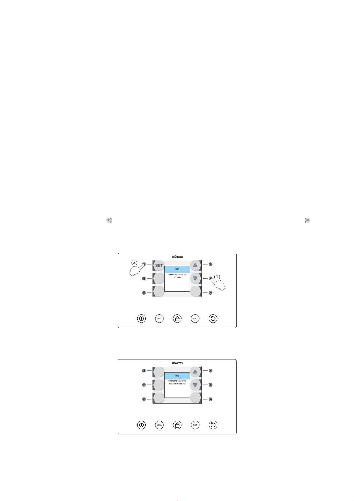
EVCO S.p.A. EVFTFT818 | Installer manual ver. 2.1 | Code 144FTFT818E214
12 USE OF THE USB PORT (ONLY AVAILABLE IN
THE MODEL EVFTFT818P7U)
12.1 Foreword
Through the USB port it is possible to make the following operation (from and in a text document):
- upload and download of the configuration parameters
- upload and download of the programs
- download of the information relative to the HACCP alarms.
The upload / download procedures are allowed on condition that the firmware of the device of origin and the one of the
device (or the devices) of destination are coincident.
The procedures are guaranteed if using the EVCO USB peripheral EVUSB4096M.
12.2 Upload and download of the configuration
parameters
To make the download of the configuration parameters operate as follows:
1. Make sure the device is in the “stand-by” status.
2. Insert an USB peripheral in the USB serial port.
3. Press and release the key (1) to select “DOWNLOAD PARAMETERS”, then press and release the key
(2): it will automatically be started the writing (into the peripheral) of a text document by name “param.txt”
(containing information about the configuration parameters); the writing procedure can take some minutes.
4. To the end of the download remove the USB peripheral from the USB port.
To make the upload of the configuration parameters operate as follows:
5. Make sure the device is in the “stand-by” status.
page 71 of 94
Page 72
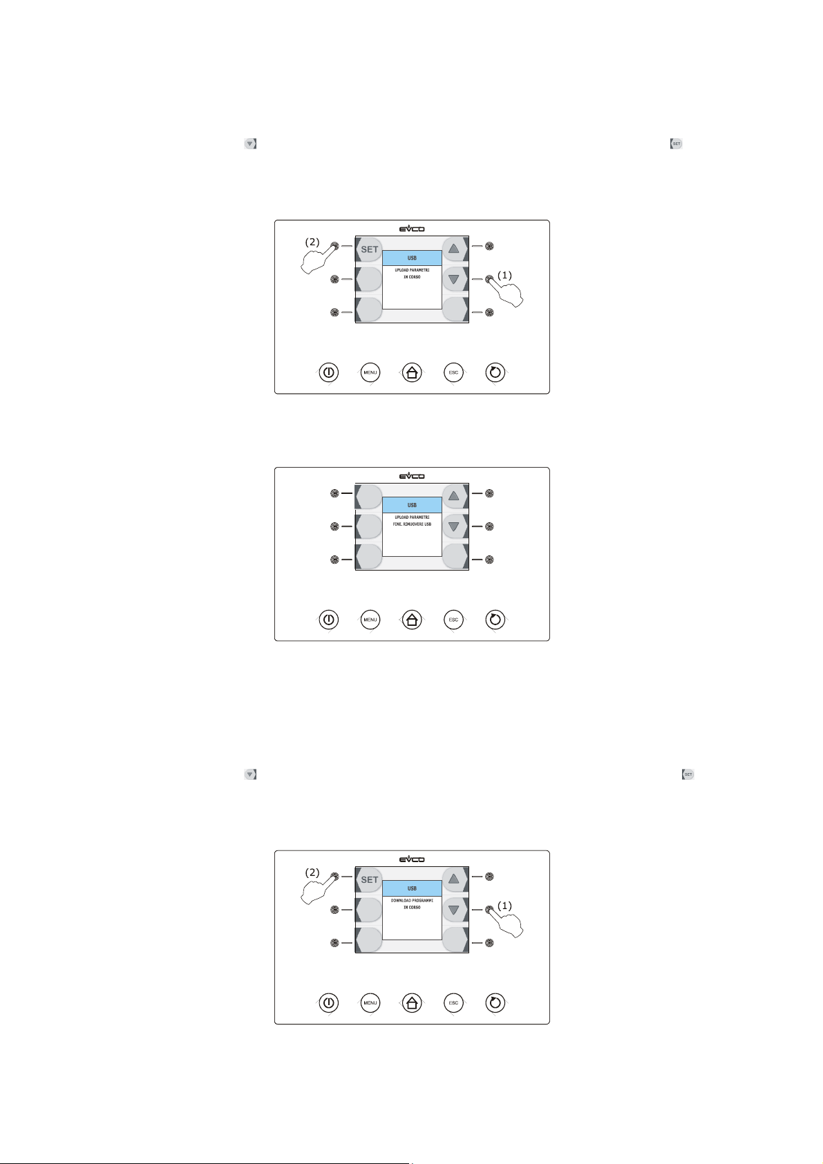
EVCO S.p.A. EVFTFT818 | Installer manual ver. 2.1 | Code 144FTFT818E214
6. Insert an USB peripheral in the USB serial port; make sure the peripheral contains the text document by name
“param.txt” (see point 3).
7. Press and release the key (1) to select “UPLOAD PARAMETERS”, then press and release the key (2): it
will automatically be started the reading (from the peripheral) of the text document by name “param.txt”
(containing information about the configuration parameters); the reading procedure can take some minutes.
8. To the end of the upload remove the USB peripheral from the USB port.
12.3 Upload and download of the programs
To make the download of the programs operate as follows:
1. Make sure the device is in the “stand-by” status.
2. Insert an USB peripheral in the USB serial port.
3. Press and release the key (1) to select “DOWNLOAD PROGRAMS”, then press and release the key (2):
it will automatically be started the writing (into the peripheral) of a text document by name “ricette.txt”
(containing information about the programs); the writing procedure can take some minutes.
page 72 of 94
Page 73
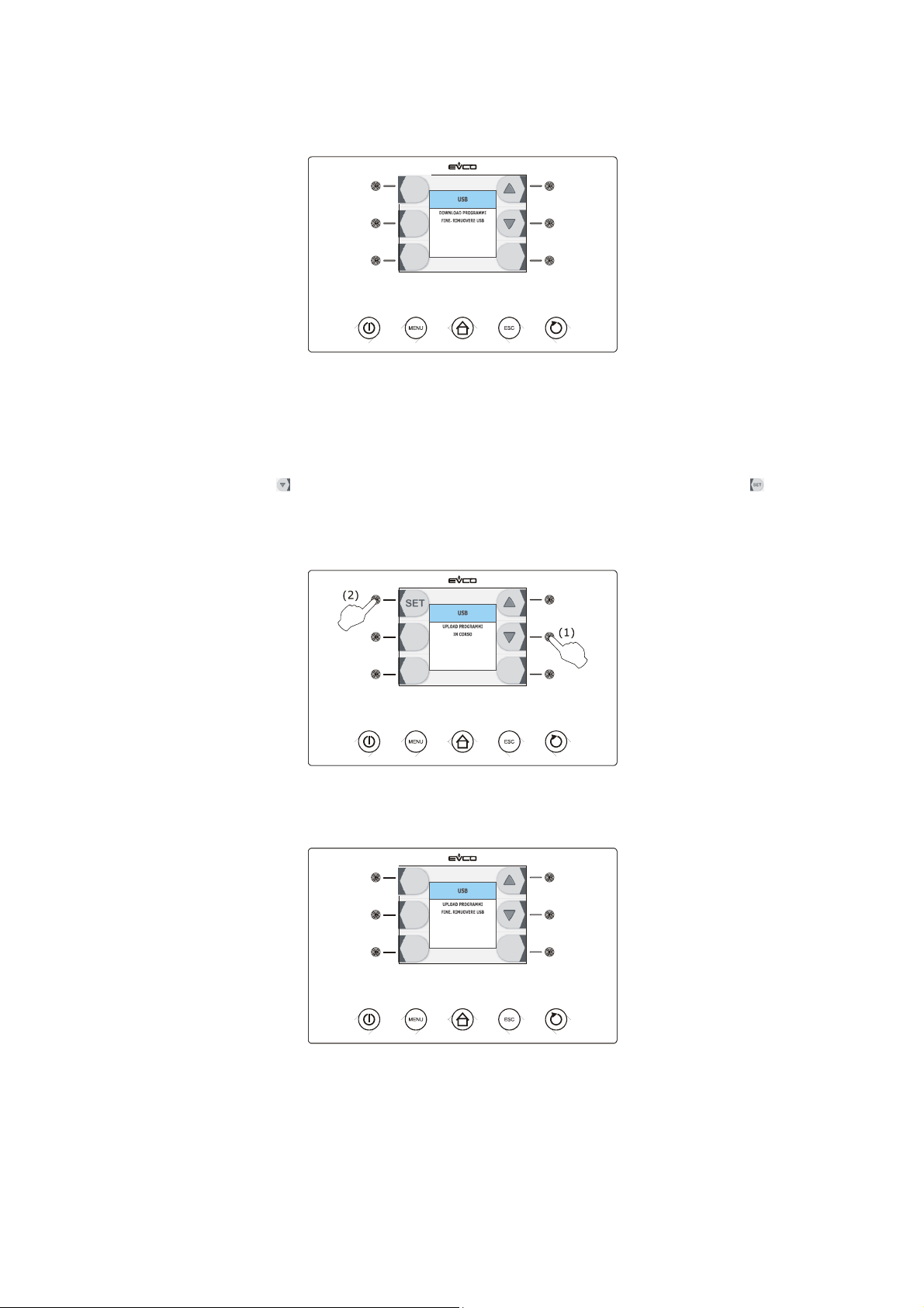
EVCO S.p.A. EVFTFT818 | Installer manual ver. 2.1 | Code 144FTFT818E214
4. To the end of the download remove the USB peripheral from the USB port.
To make the upload of the programs operate as follows:
5. Make sure the device is in the “stand-by” status.
6. Insert an USB peripheral in the USB serial port; make sure the peripheral contains the text document by name
“ricette.txt” (see point 3).
7. Press and release the key (1) to select “UPLOAD PROGRAMS”, then press and release the key (2): it
will automatically be started the reading (from the peripheral) of the text document by name “ricette.txt”
(containing information about the programs); the reading procedure can take some minutes.
8. To the end of the download remove the USB peripheral from the USB port.
page 73 of 94
Page 74
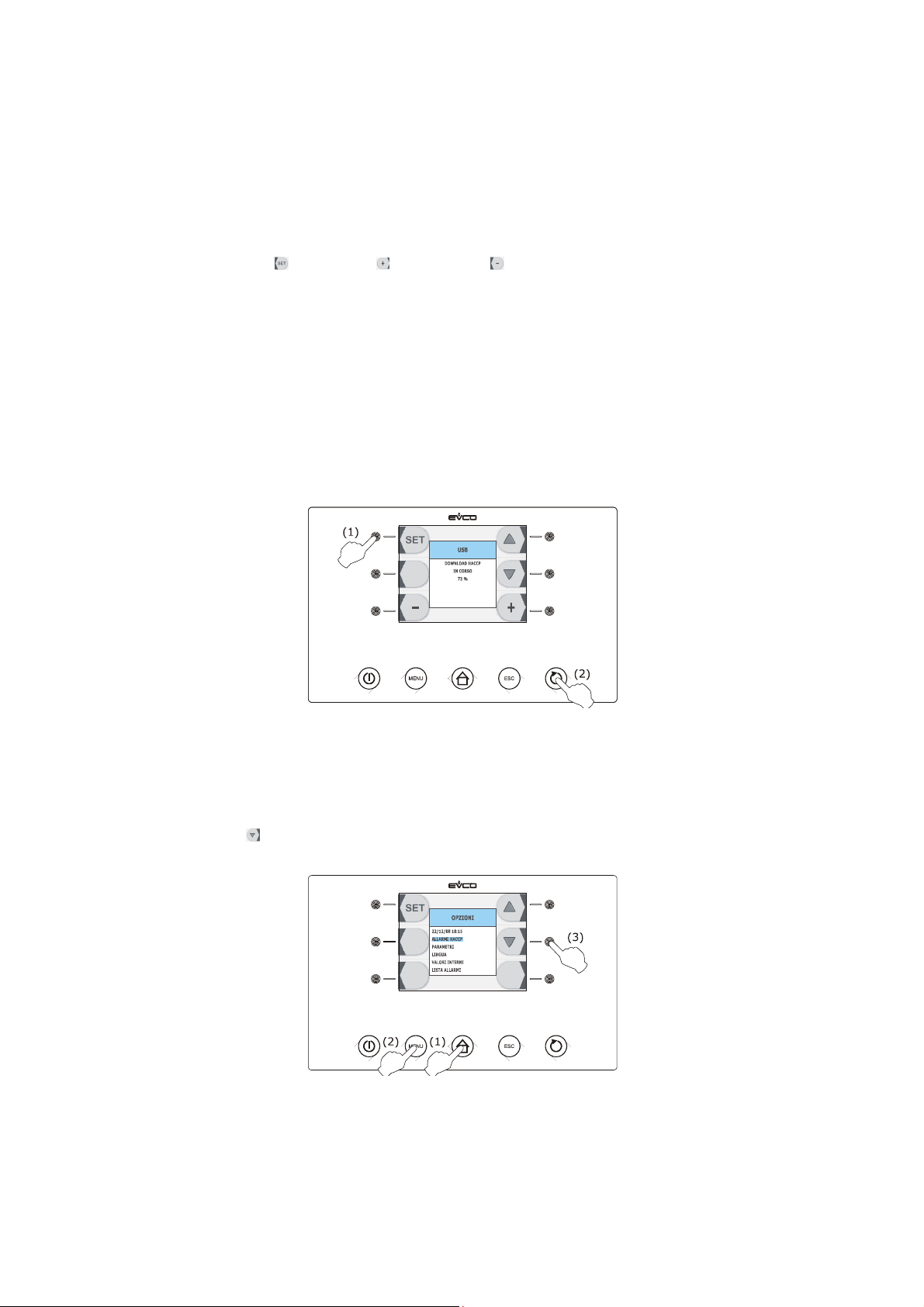
EVCO S.p.A. EVFTFT818 | Installer manual ver. 2.1 | Code 144FTFT818E214
12.4 Download of the information relative to the HACCP
alarms
To make the download of the information relative to the HACCP alarms operate as follows:
1. Make sure the device is in the “stand-by” status.
2. Insert an USB peripheral in the USB serial port.
3. Press and release the key (1), the key (2) or the key (3) to set the day and the time from which the
information must begin, then press and release the START / STOP key (4): it will automatically be started the
writing (into the peripheral) of a CSV (Comma Separated Values) document by name (for example)
“log247n00001.csv” (containing information relative to the HACCP alarms); the writing procedure can take
some minutes.
The name of the CSV document is made (with reference to the example) as follows:
- “log”: fix field
- “247”: value of paramater LA (device address)
- “n”: fix field
- “00001”: progressive number of downloads of the information relative to the HACCP alarms.
To set the kind of information to be downloadedoperate as follows:
3.1 Make sure the device is in the “on” status.
3.2 Make sure the keyboard is not locked and no procedure is in progress.
3.3 Press and release the HOME key (1), press and release the MENU key (2), then press and release
the key (3) to select “HACCP ALARMS”.
page 74 of 94
Page 75
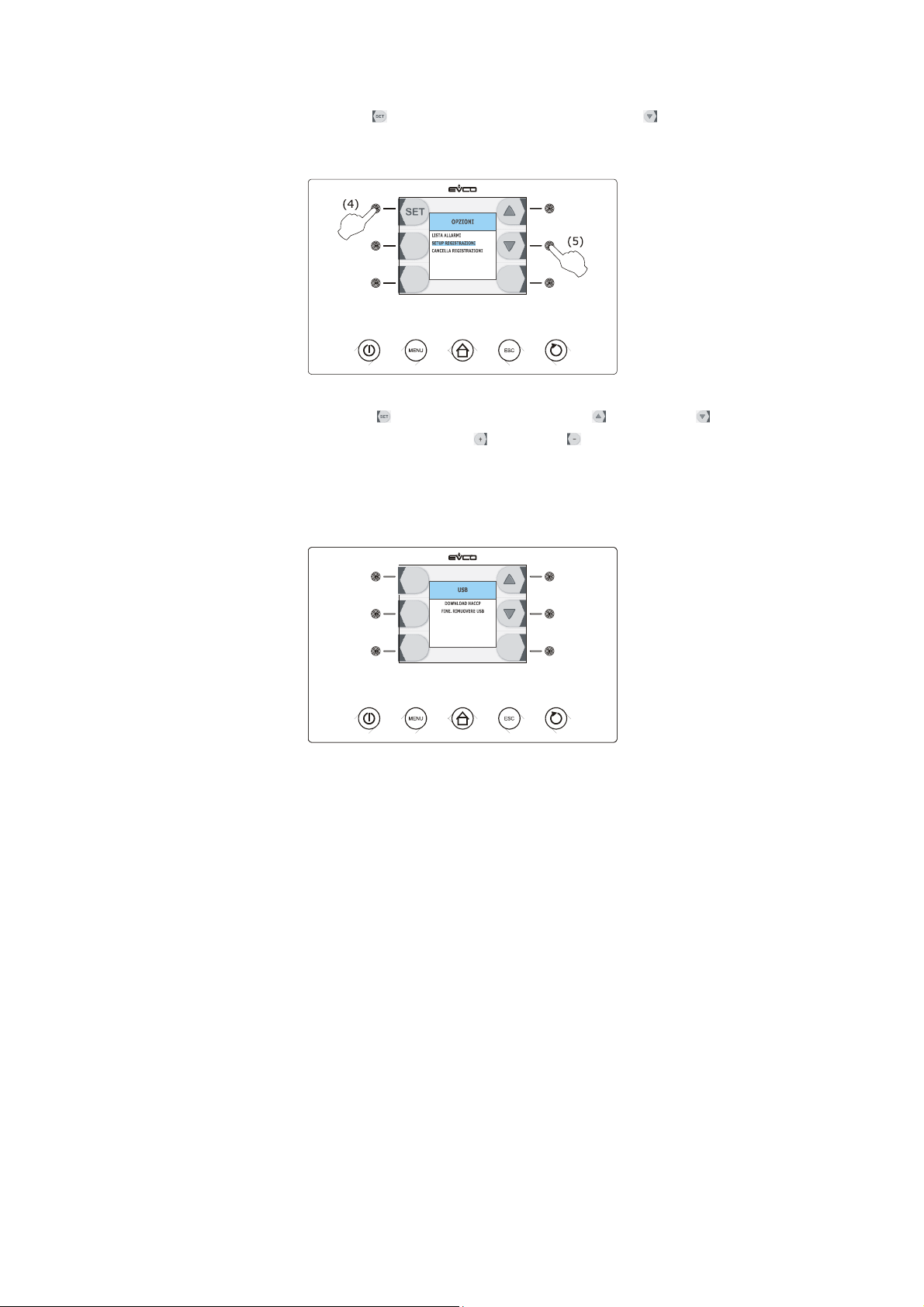
EVCO S.p.A. EVFTFT818 | Installer manual ver. 2.1 | Code 144FTFT818E214
3.4 Press and release the key (4), then press and release the key (5) to select “SETUP
RECORDING”.
3.5 Press and release the key, press and release the key or the key to select the
information, then press and release the key (ot the key) to add it (or remove it).
Operate as follows to exit the procedure:
3.6 Press and release the ESCAPE key or do not operate for 60 s.
4. To the end of the download remove the USB peripheral from the USB port.
To delete the information relative to the HACCP alarms see paragraph 9.3 “Deleting the information relative to the
HACCP alarms”.
page 75 of 94
Page 76
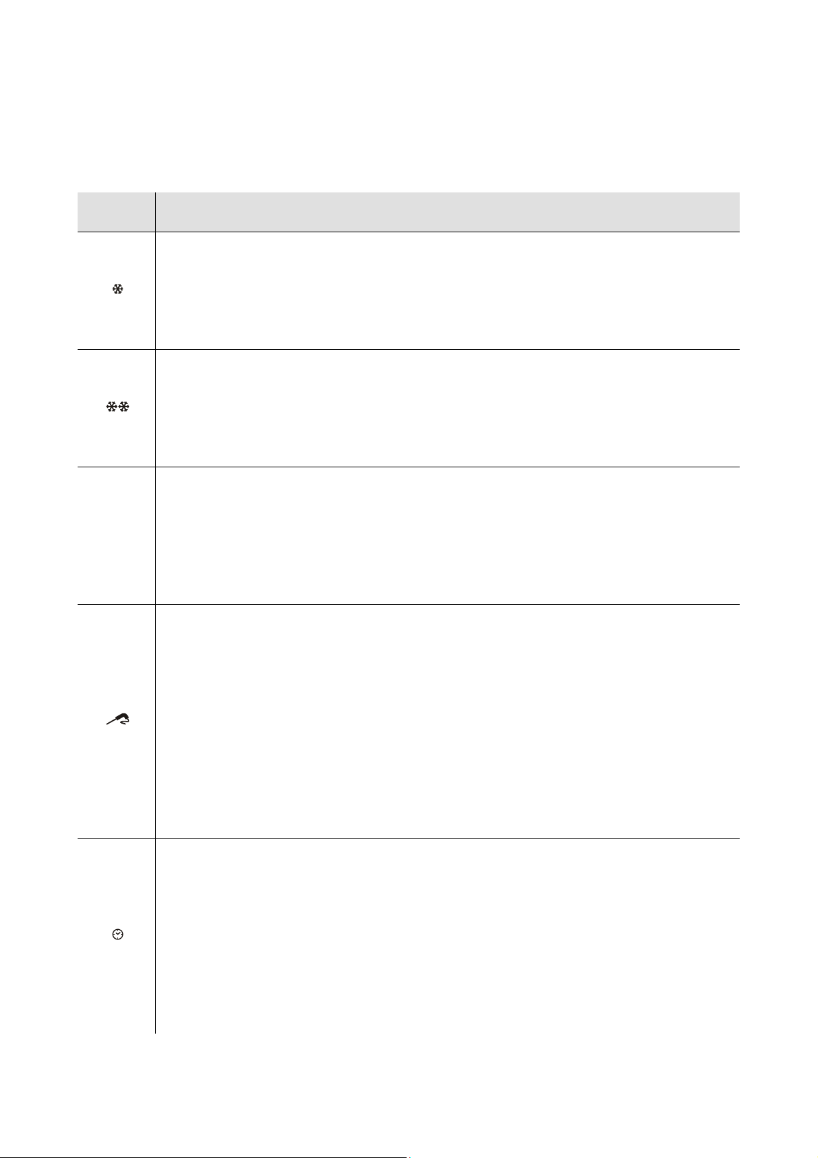
EVCO S.p.A. EVFTFT818 | Installer manual ver. 2.1 | Code 144FTFT818E214
13 SIGNALS AND INDICATIONS
13.1 Signals
The following table illustrates the meaning of the signalling LEDS.
LED Meaning
Blast chilling LED.
If it is on:
- blast chilling will be in progress (or has been performed).
If flashing:
- a blast chilling and storage cycle will have been selected.
Deep freezing LED.
If it is on:
- a soft deep freezing cycle will be in progress (or has been performed).
If flashing:
- a soft deep freezing and storage cycle will have been selected.
HARD
hard blast chilling/deep freezing LED
If it is on:
- hard blast chilling or deep freezing will be in progress (or has been performed).
If flashing:
- a hard blast chilling and storage cycle or a deep freezing and storage cycle will have been
selected.
temperature-controlled blast chilling/temperature-controlled deep freezing LED.
If it is on:
- a temperature-controlled blast chilling and storage cycle or a temperature-controlled deep
freezing and storage cycle will have been performed.
- temperature-controlled blast chilling or deep freezing will be in progress.
If flashing:
- a temperature-controlled blast chilling and storage cycle or a temperature-controlled deep
freezing and storage cycle will have been selected.
- the verification test for the correct insertion of the needle probe will not have been completed
successfully
- needle probe heating will be in progress.
time-controlled blast chilling/time-controlled deep freezing LED.
If it is on:
- a time-controlled blast chilling and storage cycle or a time-controlled deep freezing and storage
cycle will have been performed.
- time-controlled blast chilling or deep freezing will be in progress.
If flashing:
- a time-controlled blast chilling and storage cycle or a time-controlled deep freezing and storage
cycle will have been selected.
- setting the real date and time will be in progress.
page 76 of 94
Page 77

EVCO S.p.A. EVFTFT818 | Installer manual ver. 2.1 | Code 144FTFT818E214
Storage LED.
If it is on:
- storage will be in progress.
If flashing:
- work set-point modification will be in progress (cabinet temperature).
Blast chilling/deep freezing intensity LED bars (only if parameter F0 is set at 3).
They supply information relative to evaporator fan speed (for example, one bar on corresponds to
speed 1, two bars on correspond to speed 2, three bars on correspond to speed 3, etc.).
Pre-cooling LED.
If it is on:
- pre-cooling will be in progress and the cabinet temperature will have reached that established
using parameter r12.
If flashing:
- pre-cooling will be in progress and the cabinet temperature will not have reached that
established using parameter r12.
AUX
HACCP
°C
°F
min
Auxiliary LED.
If it is on:
- the cabinet light will be on
- needle probe heating will be in progress
- the UV light will be on.
HACCP LED.
If it is on:
- all information regarding HACCP alarms will not have been displayed.
If flashing:
- the device will have memorised at least one new HACCP alarm.
Degree Celsius LED.
If it is on:
- the temperature unit of measurement will be the degree Celsius.
Degree Fahrenheit LED.
If it is on:
- the temperature unit of measurement will be the degree Fahrenheit.
minutes LED.
If it is on:
- the time unit of measurement will be the minute.
If the ON/STAND-BY key is on, it means that the device will be in the “stand-by” state.
page 77 of 94
Page 78

EVCO S.p.A. EVFTFT818 | Installer manual ver. 2.1 | Code 144FTFT818E214
13.2 Indications
The following table illustrates the meaning of the indication codes.
Code Meaning
dEF Defrosting will be in progress.
Loc The keyboard is locked, see paragraph 5.10 "Lock/unlock the keyboard".
UnL The keyboard has been locked, see paragraph 5.10 "Lock/unlock the keyboard".
page 78 of 94
Page 79

EVCO S.p.A. EVFTFT818 | Installer manual ver. 2.1 | Code 144FTFT818E214
14 ALARMS
14.1 Alarms
The following table illustrates the meaning of the alarm codes.
Code Meaning
Temperature-controlled blast chilling or deep freezing not concluded within maximum duration alarm
(HACCP alarm).
Solutions:
tiM
AL
- check the value of parameters r5 and r6 and AA.
Main consequences:
- the device will memorise the alarm
- the alarm output will be activated.
Minimum temperature alarm.
Solutions:
- check the temperature of the cabinet
- check the value of parameters A1 and A2.
Main consequences:
- the alarm output will be activated.
AH
id
HP
Maximum temperature alarm (HACCP alarm).
Solutions:
- check the temperature of the cabinet
- check the value of parameters A4 and A5.
Main consequences:
- the device will memorise the alarm
- the alarm output will be activated.
Door open alarm
Solutions:
- check the door conditions
- check the value of parameters i0 and i1.
Main consequences:
- the effect established with parameter i0
- the alarm output will be activated.
High pressure alarm.
Solutions:
- check the conditions of the high pressure input
- check the value of parameters i5 and i6.
Main consequences:
- the effect established with parameter i5
- the alarm output will be activated.
page 79 of 94
Page 80

EVCO S.p.A. EVFTFT818 | Installer manual ver. 2.1 | Code 144FTFT818E214
Low pressure alarm.
Solutions:
- check the conditions of the low pressure input
LP
- check the value of the parameter i8.
Main consequences:
- the compressor and the evaporator fan will be off
- the alarm output will be activated.
Compressor circuit breaker protection alarm.
Solutions:
- check the conditions of the compressor circuit breaker protection input
CtH
- check the value of the parameter i10.
Main consequences:
- the compressor will be switched off
- the alarm output will be activated.
Power supply cut-off alarm during storage (HACCP).
Solutions:
- check the device-power supply connection
PF
- check the value of the parameter A10.
Main consequences:
- the device will memorise the alarm
- the alarm output will be activated.
COH
CSd
ALARM
San
Condenser overheated alarm.
Solutions:
- check the temperature of the condenser
- check the value of the parameter C6.
Main consequences:
- the condenser fan will be switched on
- the alarm output will be activated.
Compressor blocked alarm.
Solutions:
- check the temperature of the condenser
- check the value of the parameter C7
- disconnect the device power supply and clean the condenser.
Main consequences:
- if the error occurs during the “stand-by” status, no operating cycles can be selected or started
- if the error occurs during an operating cycle, the cycle will be interrupted
- the alarm output will be activated.
Sanification alarm.
Solutions:
- check the correct insertion of the needle probe and check the value of parameters r17 and r18.
Main consequences:
- the cycle of sanification will be stopped.
page 80 of 94
Page 81

EVCO S.p.A. EVFTFT818 | Installer manual ver. 2.1 | Code 144FTFT818E214
15 ERRORS
15.1 Errors
The following table illustrates the meaning of the error codes.
Code Meaning
Cabinet probe error.
Solutions:
- check the value of the parameter P0
- check the integrity of the probe
- check the device-probe connection
- check the temperature of the cabinet.
Main consequences:
Pr1
- if the error occurs during the “stand-by” status, no operating cycles can be selected or started
- if the error occurs during blast chilling or deep freezing, the cycle will be interrupted
- if the error occurs during storage, compressor activity will depend on parameters C4 and C5 or
C9
- defrosting will never be activated
- the minimum temperature alarm (“AL” code) will never be activated
- the maximum temperature alarm (“AH” code) will never be activated
- the door heating elements will never be switched on
- the alarm output will be activated.
Pr2
Pr3
Evaporator probe error.
Solutions:
- the same as the cabinet probe error (“Pr1” code) but relative to the evaporator probe.
Main consequences:
- if parameter P4 is set at 1, defrosting will last for the period of time established with parameter
d3
- if parameter F0 is set at 1, parameter F16 will have no effect
- if parameter F2 is set at 1, the device will operate as if it were set at 2.
- the alarm output will be activated.
Condenser probe error.
Solutions:
- the same as the cabinet probe error (“Pr1” code) but relative to the condenser probe.
Main consequences:
- the condenser fan will operate parallel to the compressor
- the overheated condenser alarm (“COH” code) will never be activated
- the compressor blocked alarm (“CSd” code) will never be activated
- the alarm output will be activated.
page 81 of 94
Page 82

EVCO S.p.A. EVFTFT818 | Installer manual ver. 2.1 | Code 144FTFT818E214
Needle probe error 1.
Solutions:
- the same as the cabinet probe error (“Pr1” code) but relative to the needle probe 1.
ain consequences if parameter P3 is set at 1:
- if the error occurs during the “stand-by” status, temperature-controlled operating cycles will be
started by time-control
Pr4
- if the error occurs during temperature-controlled blast chilling, this will have duration of the
time set by parameter r1
- if the error occurs during temperature-controlled deep freezing, this will have duration of the
time set by parameter r2
- if the error occurs during needle probe heating, this operation will be interrupted.
- the alarm output will be activated.
ain consequences if parameter P3 is set at 2 or at 3:
- the device will not use needle probe 1.
Needle probe error 2.
Solutions:
Pr5
- the same as the cabinet probe error (“Pr1” code) but relative to the needle probe 2.
Main consequences:
- the device will not use needle probe 2.
Pr6
rtc
ErC
ErL
Needle probe error 3.
Solutions:
- the same as the cabinet probe error (“Pr1” code) but relative to the needle probe 3.
Main consequences:
- the device will not use needle probe 3.
Clock error.
Solutions:
- set the real date and time again.
Main consequences:
- the device does not memorise the date or time at which the HACCP alarm occurred or its
duration
- the alarm output will be activated.
User interface-control module compatibility.
Solutions:
- check that the user interface and the control module are compatible.
Main consequences:
- the control module will continue to operate normally.
User interface-control module communication error.
Solutions:
- check user interface-control module control module.
Main consequences:
- the control module will continue to operate normally.
page 82 of 94
Page 83
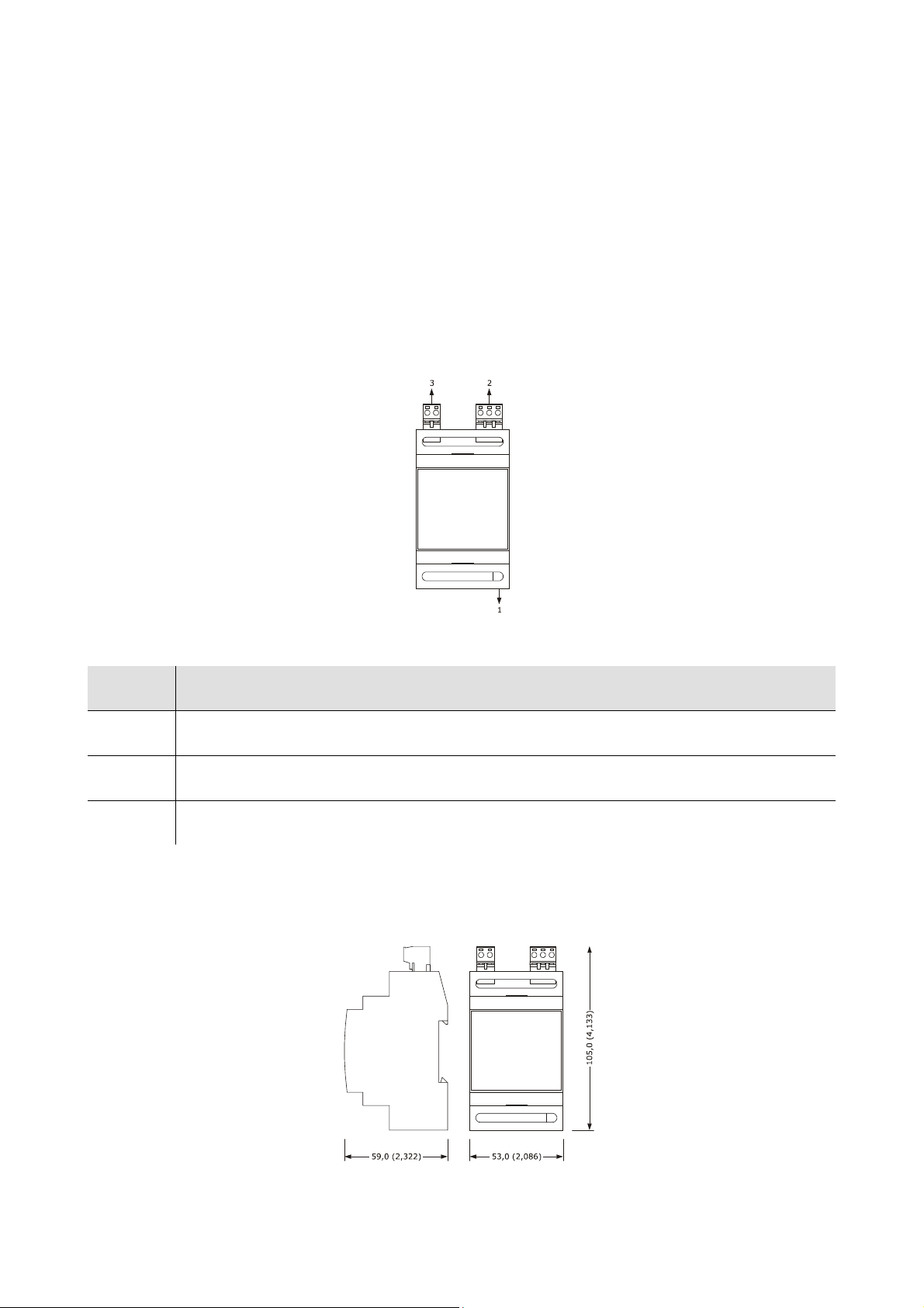
EVCO S.p.A. EVFTFT818 | Installer manual ver. 2.1 | Code 144FTFT818E214
16 ACCESSORIES
16.1 Data recording device EVUSBREC01
16.1.1 Introduction
EVUSBREC01 is a data recording device.
Using the device, it is possible to record controller data and their download (via USB, into a text document).
16.1.2 Description
The following drawing illustrates the aspect of the EVUSBREC01.
The following table illustrates the meaning of the EVUSBREC01 parts.
Part Meaning
1 USB type serial port
2 RS-485 type serial port
3 power supply
16.1.3 Dimensions
The following drawing illustrates the EVUSBREC01 dimensions; these are expressed in mm (in).
page 83 of 94
Page 84
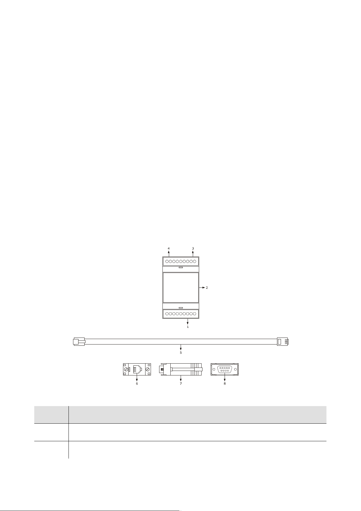
EVCO S.p.A. EVFTFT818 | Installer manual ver. 2.1 | Code 144FTFT818E214
16.1.4 Connection to the device
Operate as follows:
1. Cut the device power supply off.
2. Cut the EVUSBREC01 power supply off.
3. Connect the device RD-485 serial port to the EVUSBREC01 RS-485 type serial port.
4. Connect the device power supply.
5. Connect the EVUSBREC01 power supply.
For further information, consult the documentation relative to EVUSBREC01.
16.2 Optoisolated RS-485/RS-232 serial interface
EVIF21RS7I
16.2.1 Introduction
EVIF21RS7I is an optoisolated RS-485/RS-232 serial interface.
The interface can be used to connect the controller to the Parameters Manager set-up software system.
The Personal Computer must have a free COM port; to connect the driver via a USB port, the adapter must also be
used from COM to USB 0810500011.
16.2.2 Description
The following drawing illustrates the aspect of the EVIF21RS7I.
The following table illustrates the meaning of the EVIF21RS7I parts.
Part Meaning
1 RS-485 type serial port
2 EVIF21RS7I
page 84 of 94
Page 85
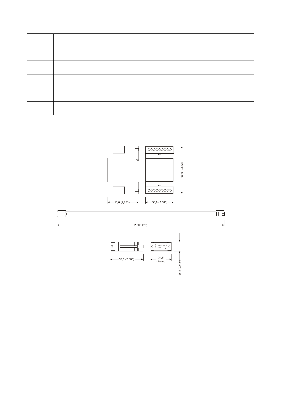
EVCO S.p.A. EVFTFT818 | Installer manual ver. 2.1 | Code 144FTFT818E214
3 power supply
4 RS-232 type serial port
5 1256800042 telephone cable
6 RJ connector
7 1256800079 adapter
8 DB connector
16.2.3 Dimensions
The following drawing illustrates the EVIF21RS7I dimensions; these are expressed in mm (in).
16.2.4 Connection to the device
Operate as follows:
1. Cut the device power supply off.
2. Connect the device RD-485 serial port to the EVIF21RS7I RS-485 type serial port.
3. Insert one end of the telephone cable 1256800042 into the EVIF21RS7I RS-232 serial port.
4. Insert the other end of the telephone cable 1256800042 into the 1256800079 adapter RJ connector.
5. Connect the 1256800079 adapter DB connector to a Personal Computer COM, in which Parameters Manager is
installed.
6. Connect the device power supply.
For further information, consult the documentation relative to Parameters Manager.
page 85 of 94
Page 86
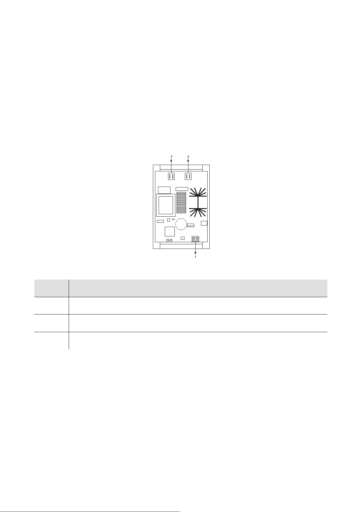
EVCO S.p.A. EVFTFT818 | Installer manual ver. 2.1 | Code 144FTFT818E214
16.3 Phase cut speed regulator for single phase fans
EVDFAN1
16.3.1 Introduction
EVDFAN1 is a phase cut speed regulator for single phase fans.
The regulator control signal is the PWM type, the same supplied by the controller analogue output.
The maximum current allowed on the fan is 5 A.
16.3.2 Description
The following drawing illustrates the aspect of the EVDFAN1.
The following table illustrates the meaning of EVDFAN1 parts.
Part Meaning
1 control signal input
2 power supply
3 phase cut output
page 86 of 94
Page 87
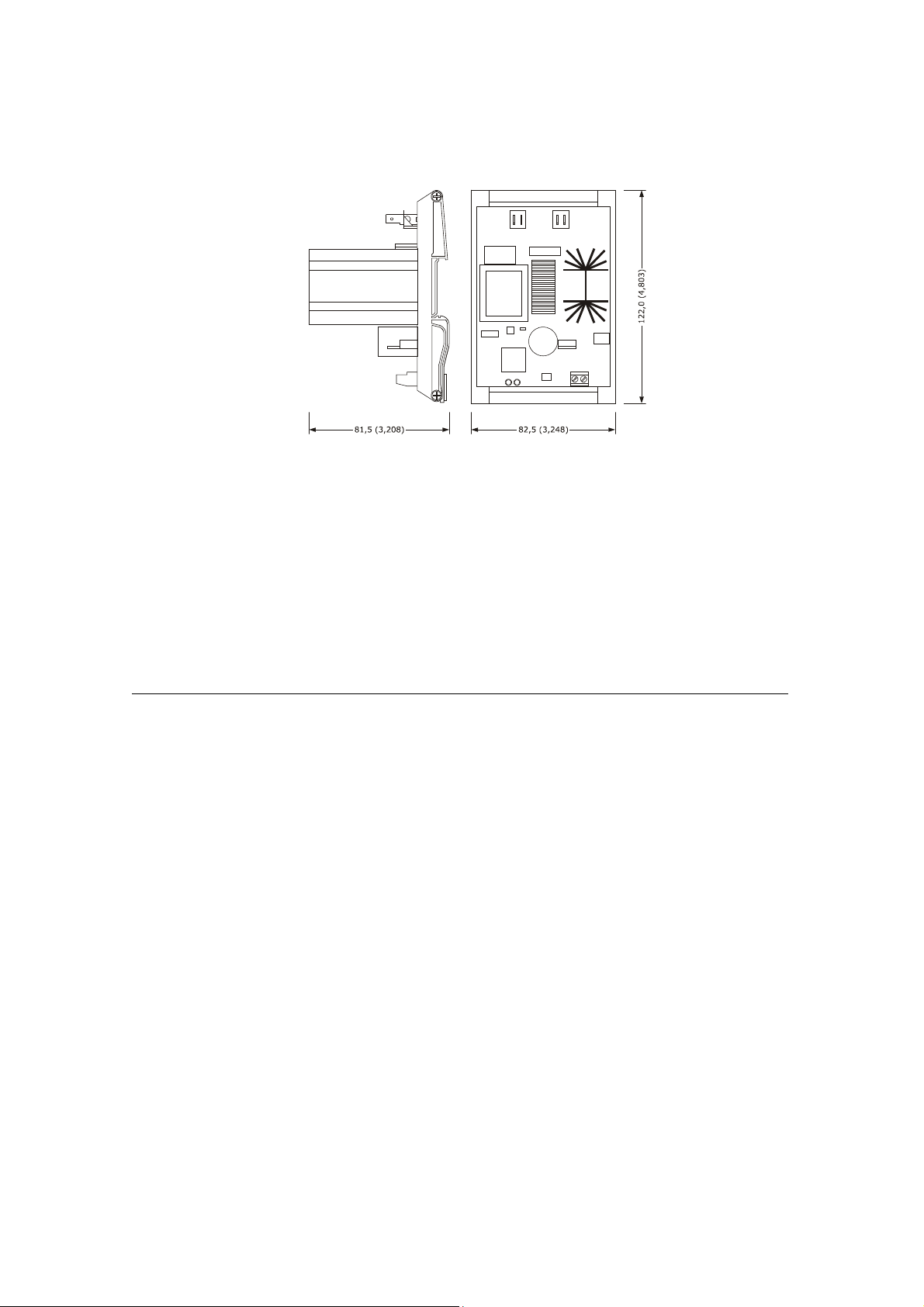
EVCO S.p.A. EVFTFT818 | Installer manual ver. 2.1 | Code 144FTFT818E214
16.3.3 Dimensions
The following drawing illustrates the EVDFAN1 dimensions; these are expressed in mm (in).
16.3.4 Connection to the device
Operate as follows:
1. Make sure that parameter F0 is set at 3.
2. Cut the device power supply off.
3. Cut the EVDFAN1 power supply off.
4. Connect the device PWM analogue output to the EVDFAN1 control signal input.
5. Connect the evaporator fan to the EVDFAN1 phase cut output.
6. Connect the device power supply.
7. Connect the EVDFAN1 power supply.
In order to use EVDFAN1, the phase that powers the controller must be the same that powers EVDFAN1.
For further information, consult the documentation relative to EVDFAN1.
page 87 of 94
Page 88
EVCO S.p.A. EVFTFT818 | Installer manual ver. 2.1 | Code 144FTFT818E214
17 TECHNICAL DATA
17.1 Technical data
Purpose of the device: blast chiller controller.
user interface control module
Execution:
Dimensions:
Installation:
Protection rating:
board without cover behind a
Plexiglas sheet.
user interface control module
200.0 x 135.0 x 28.0 ±0.6 mm
(7.874 x 5.314 x 1.102
±0.023 in; L x H x D).
user interface control module
back panel via studs. on flat surface, with spacers.
user interface control module
IP65. IP00.
user interface control module
board without cover.
166.0 x 116.0 x 44.0 mm
(6.535 x 4.566 x 1.732 in;
L x H x D).
removable screw terminal board
Connections:
Temperature of use: from 0 to 55 °C (from 32 to 131 °F).
Storage temperature: from -10 to 70 °C (from 14 to 158 F).
Humidity for use: from 10% to 90% relative humidity without condensate.
Pollution situation: normal.
Power supply:
(control module and RS-485
serial port).
The maximum length of the user interface
-control module connection is 10 m (32.808 ft).
user interface control module
supplied from the control
module.
removable screw terminal board
(user interface, power supply,
inputs, outputs).
230 VAC (±15%), 50/60 Hz (±3
Hz), 10 VA max.
page 88 of 94
Page 89
EVCO S.p.A. EVFTFT818 | Installer manual ver. 2.1 | Code 144FTFT818E214
Overvoltage category: integrated control.
incorporated (with condenser).
Battery autonomy in the event of a power-cut: 24 h with battery
Clock:
fully charged.
Battery charging time: 2 min (the battery is charged by the device
power supply).
Signal buzzer and alarm: incorporated.
6 inputs (cabinet probe, “multipoint” needle probe with up to three
sensors, evaporator probe and condenser probe) can be set via
configuration parameter for PTC/NTC probes.
PTC type analogue inputs (990 Ω @ 25°C, 77°F)
Type of sensor: KTY 81-121.
Field of measurement: from -50 to 150°C
(from -58 to 302°F).
Analogue inputs:
Resolution: 1 °C (1 °F).
Protection: none.
NTC type analogue inputs (10K Ω @ 25°C, 77°F)
Type of sensor: ß3435.
Field of measurement: from -40 to 105°C
(from -40 to 220 °F).
Resolution: 1 °C (1 °F).
Protection: none.
4 inputs (door micro switch, high pressure, low pressure and
compressor circuit breaker protection), which can be set via
configuration parameter due to normally open contact/normally
Digital inputs:
closed contact (potential-free contact, 5 VDC, 2 mA)
Digital inputs
Power supply: none.
Protection: none.
Displays: 320 x 240 pixel (3.5 inch) colour TFT graphics display
Analogue outputs: 1 PWM output for management of the evaporator fan.
page 89 of 94
Page 90

EVCO S.p.A. EVFTFT818 | Installer manual ver. 2.1 | Code 144FTFT818E214
8 outputs (electromechanical relays):
- 1 x 16 A res. output @ 250 VAC SPST type (K1) for
compressor management
- 6 x 8 A res. outputs @ 250 VAC of which five SPST type for
Digital outputs:
managing defrosting (K2), the evaporator fan (K3), the
condenser fan (K4), cabinet light or UV light (K7), the pump
down valve or alarm output (K8) and one SPDT type for
management of the door heating elements (K5)
- 1 x 16 A res. output @ 250 VAC SPDT type (K6) for heating
management of the needle probe.
Type of actions and complementary
features:
Communication port:
1C.
2 ports:
- 1 RS-48 serial port with MODBUS communication protocol
- 1 USB serial port (only available in the model
EVFTFT818P7U).
page 90 of 94
Page 91

EVCO S.p.A. EVFTFT818 | Installer manual ver. 2.1 | Code 144FTFT818E214
Notes
______________________________________________________________________________________________
______________________________________________________________________________________________
______________________________________________________________________________________________
______________________________________________________________________________________________
______________________________________________________________________________________________
______________________________________________________________________________________________
______________________________________________________________________________________________
______________________________________________________________________________________________
______________________________________________________________________________________________
______________________________________________________________________________________________
______________________________________________________________________________________________
______________________________________________________________________________________________
______________________________________________________________________________________________
______________________________________________________________________________________________
______________________________________________________________________________________________
______________________________________________________________________________________________
______________________________________________________________________________________________
______________________________________________________________________________________________
______________________________________________________________________________________________
______________________________________________________________________________________________
______________________________________________________________________________________________
______________________________________________________________________________________________
______________________________________________________________________________________________
page 91 of 94
Page 92

EVCO S.p.A. EVFTFT818 | Installer manual ver. 2.1 | Code 144FTFT818E214
______________________________________________________________________________________________
______________________________________________________________________________________________
______________________________________________________________________________________________
______________________________________________________________________________________________
______________________________________________________________________________________________
______________________________________________________________________________________________
______________________________________________________________________________________________
______________________________________________________________________________________________
______________________________________________________________________________________________
______________________________________________________________________________________________
______________________________________________________________________________________________
______________________________________________________________________________________________
______________________________________________________________________________________________
______________________________________________________________________________________________
______________________________________________________________________________________________
______________________________________________________________________________________________
______________________________________________________________________________________________
______________________________________________________________________________________________
______________________________________________________________________________________________
______________________________________________________________________________________________
______________________________________________________________________________________________
______________________________________________________________________________________________
______________________________________________________________________________________________
______________________________________________________________________________________________
page 92 of 94
Page 93

EVCO S.p.A. EVFTFT818 | Installer manual ver. 2.1 | Code 144FTFT818E214
EVFTFT818
Controller in split execution for temperature-controlled blast chillers with capacitive touch-key user interface, which
can be integrated into the unit
Installer manual ver. 2.1
PT - 51 / 12
Code 144FTFT818E214
This document is exclusive property of EVCO. Reproduction and disclosure are prohibited without express authorisation
from EVCO.
EVCO is not liable for any features, technical data and possible errors stated in this document or deriving from use of
the same.
EVCO cannot be considered liable for damage caused by failure to comply with warnings given in this document.
EVCO reserves the right to make any changes without forewarning, without jeopardising the basic safety and
operating features.
page 93 of 94
Page 94

EVCO S.p.A. EVFTFT818 | Installer manual ver. 2.1 | Code 144FTFT818E214
EVCO S.p.A.
Via Mezzaterra 6, 32036 Sedico Belluno ITALIA
Tel. 0437 / 8422
Fax 0437 / 83648
www.evco.it
page 94 of 94
 Loading...