

Page 1
EVCO S.p.A. EVFTFT618 | Installer manual ver. 2.2 | Code 144FTFT618E224
EVFTFT618
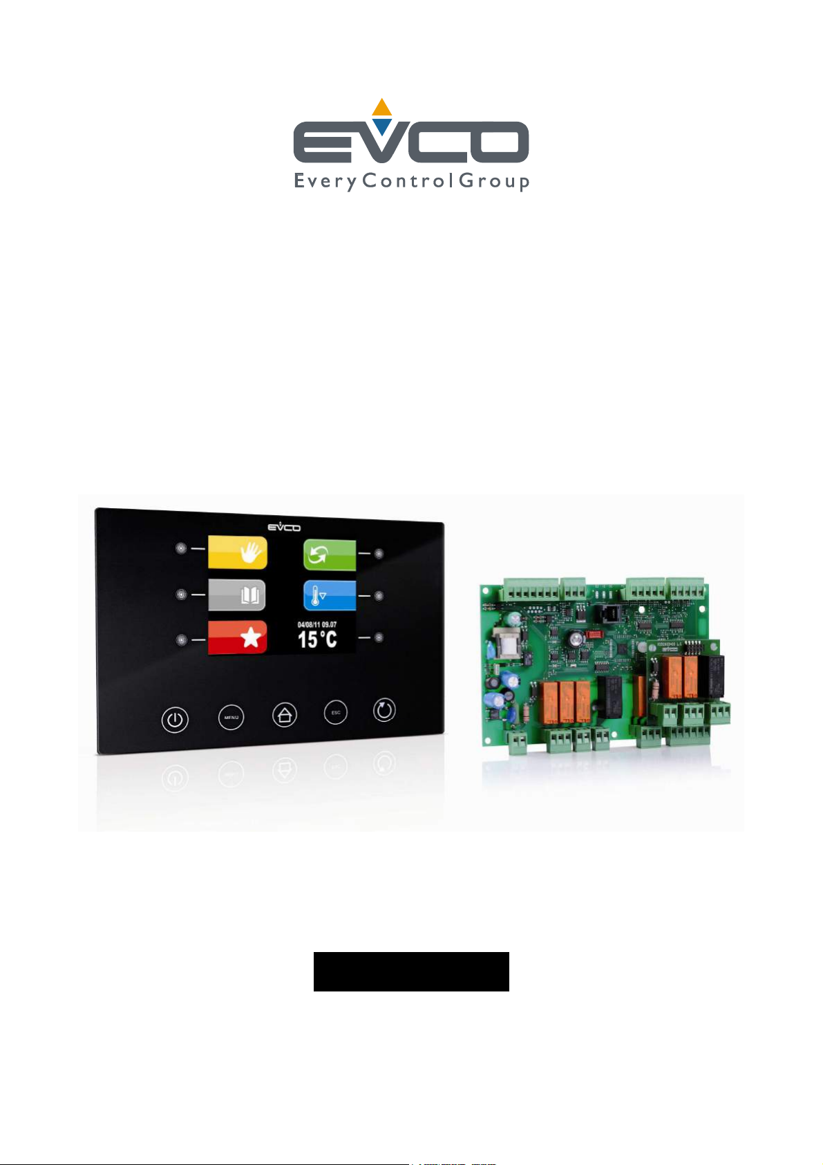
Split execution controller for management
of retarder-proofer cabinets/cells with
capacitive type user interface and TFT
graphic display
ENGLISH
INSTALLER MANUAL ver. 2.2
CODE 144FTFT618E224
Page 1 of 62
Page 2
EVCO S.p.A. EVFTFT618 | Installer manual ver. 2.2 | Code 144FTFT618E224
Important
Important
Read this document thoroughly before installation and before use of the device and follow all recommendations; keep
this document with the device for future consultation.
The following symbols support reading of the document:
indicates a suggestion
indicates a warning.
The device must be disposed of in compliance with local Standards regarding the collection of electric and electronic
equipment.
Page 2 of 62
Page 3

EVCO S.p.A. EVFTFT618 | Installer manual ver. 2.2 | Code 144FTFT618E224
Index
1 INTRODUCTION ................................................................................................................................... 5
1.1 Introduction ........................................................................................................................................ 5
1.2 Summary table of the main features and the models available ................................................................... 6
2 DESCRIPTION ...................................................................................................................................... 8
2.1 Description of the user interface ............................................................................................................ 8
2.2 Description of the control module ........................................................................................................... 9
3 DIMENSIONS AND INSTALLATION ........................................................................................................ 10
3.1 User interface dimensions ................................................................................................................... 10
3.2 Control module dimensions ................................................................................................................. 10
3.3 User interface installation .................................................................................................................... 11
3.4 Control module installation .................................................................................................................. 11
3.5 Installation warnings .......................................................................................................................... 11
4 ELECTRIC CONNECTION ...................................................................................................................... 12
4.1 Electric connection ............................................................................................................................. 12
4.1.1 Connection of the terminating resistors of the communication port ................................................... 13
4.1.2 Insertion of the RS-485 serial port terminating resistor ................................................................... 14
4.2 Warnings for the electric connection ..................................................................................................... 14
5 USER INTERFACE ............................................................................................................................... 15
5.1 Preliminary notes ............................................................................................................................... 15
5.2 Device commissioning ........................................................................................................................ 15
5.3 Switching the Device On/Off ................................................................................................................ 16
5.4 The display ........................................................................................................................................ 16
6 OPERATION ....................................................................................................................................... 17
6.1 Preliminary notes ............................................................................................................................... 17
6.1.1 Pre-selection page ...................................................................................................................... 19
6.1.2 Setting and execution of a manual cycle ........................................................................................ 20
6.1.3 Setting an automatic cycle ........................................................................................................... 21
6.1.4 Execution of an automatic cycle ................................................................................................... 22
6.1.5 The PROGRAMS menu ................................................................................................................. 23
6.1.5.1 Modify Date and Time of Automatic Cycle End .................................................................... 23
6.1.6 The FAVOURITES menu ............................................................................................................... 24
6.1.7 The PRE-COOLING menu ............................................................................................................. 25
6.1.8 The PRE-SELECTION PAGE OPTIONS menu .................................................................................... 26
6.1.8.1 The SERVICE menu ................................................................................................................ 27
7 Detail Meaning Icons Status Regulators ................................................................................................ 28
7.1 Silencing the buzzer ........................................................................................................................... 28
8 keyboard lock .................................................................................................................................... 28
8.1 Manual keyboard lock ......................................................................................................................... 28
8.2 Automatic keyboard lock ..................................................................................................................... 28
9 Regulations ....................................................................................................................................... 29
9.1 Pre-cooling ........................................................................................................................................ 29
9.2 Temperature regulation ....................................................................................................................... 29
9.2.1 Generating cold .......................................................................................................................... 29
9.2.2 Generating heat ......................................................................................................................... 30
9.3 Regulation of humidity ........................................................................................................................ 30
9.3.1 Humidification management ........................................................................................................ 31
Page 3 of 62
Page 4

EVCO S.p.A. EVFTFT618 | Installer manual ver. 2.2 | Code 144FTFT618E224
9.3.2
Dehumidification management ..................................................................................................... 31
10 Loads management ............................................................................................................................ 31
10.1 Management of the compressor ....................................................................................................... 31
10.2 Pump-down management ................................................................................................................ 31
10.3 Management of the evaporator fan ................................................................................................... 32
10.4 Defrosting management .................................................................................................................. 32
10.5 Management of the heating elements ............................................................................................... 33
10.5.1 Cabinet step heating management ............................................................................................... 33
10.6 Management of the steam generator ................................................................................................ 33
10.7 Humidification management ............................................................................................................ 33
10.7.1 Management of humidity without transducer (rU0 = 1) ................................................................... 33
10.7.2 Management of humidity with transducer (rU0 = 0) ........................................................................ 33
10.8 Dehumidification management ......................................................................................................... 34
10.8.1 Management via extractor fan/dehumidifier ................................................................................... 34
10.8.2 Management via cooling plant activation ....................................................................................... 34
10.9 Management of the condenser fan .................................................................................................... 34
10.10 Cabinet light management............................................................................................................... 34
11 Alarms .............................................................................................................................................. 35
12 Management of the Host USB port on the board ..................................................................................... 38
13 Parameters ........................................................................................................................................ 39
14 Accessories ....................................................................................................................................... 47
14.1 Phase cut speed regulator for single phase fans EVDFAN1 ................................................................... 47
14.1.1 Introduction ............................................................................................................................... 47
14.1.2 Description ................................................................................................................................ 47
14.1.3 Dimensions ................................................................................................................................ 48
14.1.4 Connection to the device ............................................................................................................. 48
14.2 Synoptic Panel EVC25T00X7XXX04 ................................................................................................... 48
14.3 Optoisolated RS-485/RS-232 serial interface EVIF21RS7I .................................................................... 50
14.3.1 Introduction ............................................................................................................................... 50
14.3.2 Description ................................................................................................................................ 50
14.3.3 Dimensions ................................................................................................................................ 51
14.3.4 Connection to the device ............................................................................................................. 51
14.4 Non-isolated RS-485/USB serial interface EVIF20SUXI ........................................................................ 52
14.4.1 Introduction ............................................................................................................................... 52
14.4.2 Description ................................................................................................................................ 52
14.4.3 Dimensions ................................................................................................................................ 53
14.4.4 Connection to the device ............................................................................................................. 53
15 TECHNICAL DATA ............................................................................................................................... 54
15.1 Technical data ................................................................................................................................ 54
Page 4 of 62
Page 5

EVCO S.p.A. EVFTFT618 | Installer manual ver. 2.2 | Code 144FTFT618E224
1 INTRODUCTION
1.1 Introduction
EVFTFT618 is a digital controller studied to manage retarder proofer cabinets/cells, which can be mechanically and
aesthetically integrated into the unit.
The controller is fitted with:
- clock, signal buzzer and alarm
- 4 analogue inputs of which 3 for PTC/NTC probes and 1 for 4-20mA
- 4 digital inputs (door micro switch, compressor circuit breaker, high pressure and low pressure protection)
- 1 PWM analogue output for management of the evaporator fan
- 8 digital outputs (electromechanical relays), 1 x 16 A res. @ 250 VAC for compressor management, 1
x 16 A res. @ 250 VAC for heating element management and 6 x 8 A res. @ 250 VAC for management of the cabinet
light, humidifier, dehumidifier/condenser fan, defrosting, steam generator and pump-down valve/evaporator fan.
- RS-48 serial port with MODBUS communication protocol
- USB port on board.
The controller supplies a complete control for retarder-proofer cabinets or cells for confectionery and bread-making,
through the automatic management of the complete mixture retarder-proofer cycle.
The machine can have 3 different states, defined unmistakeably in the following way through the entire document:
STAND-BY status: the machine is off but powered, it is not possible to perform any selection/cycle start command
ON status: the machine is on but in stand-by for operating cycle selection
RUN status: the machine is on with a cycle in progress
Page 5 of 62
Page 6
EVCO S.p.A. EVFTFT618 | Installer manual ver. 2.2 | Code 144FTFT618E224
1.2 Summary table of the main features and the models
available
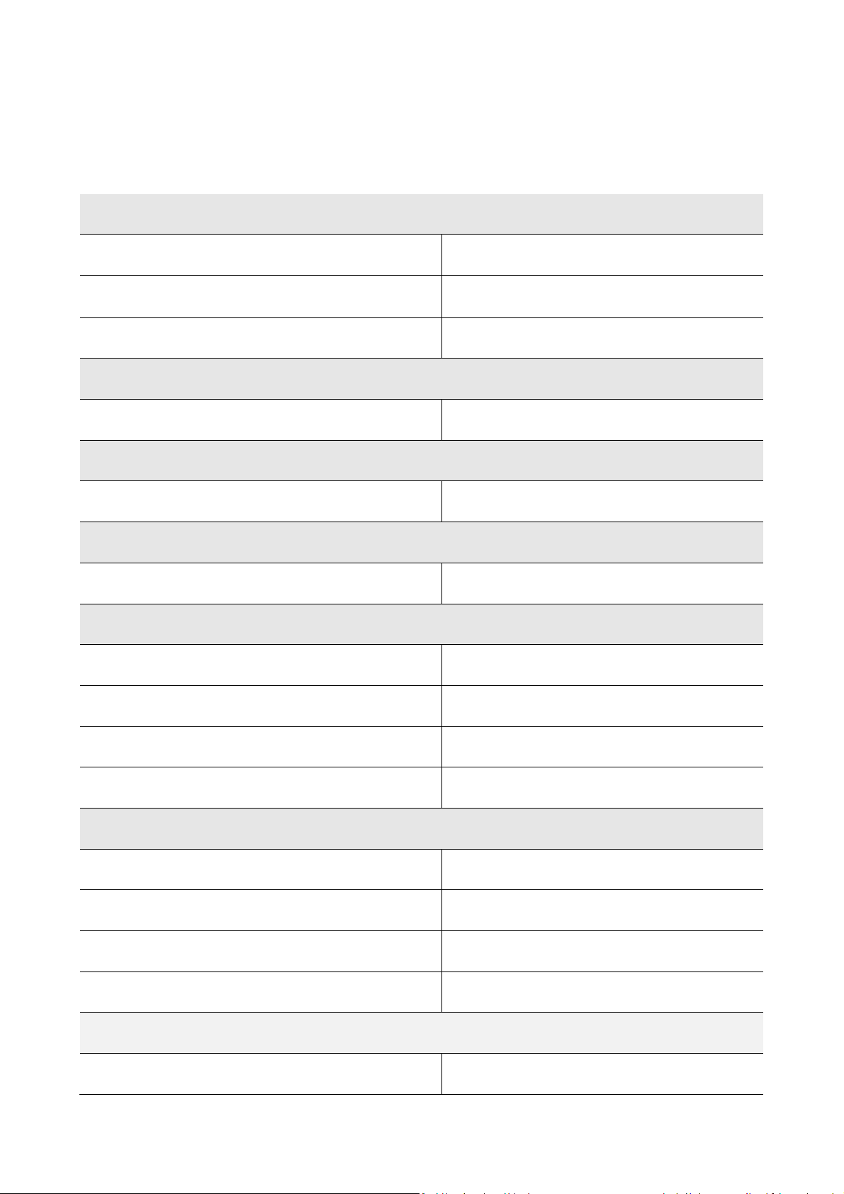
The following table illustrates the main features of the device.
“ / “ indicates the feature can be set via a configuration parameter.
User interface (without cover)
200.0 x 135.0 mm (7.874 x 13.498 cm; L x H) •
320 x 240 pixel
(3.5 inch) colour TFT graphics display
number of keys (capacitive touch-key type) 11
Control module (without cover)
166.0 x 116.0 mm (6.535 x 11.598 cm; L x H) •
Connections
removable screw terminal board •
Power supply
115-230 VAC •
Analogue inputs
cabinet probe PTC/NTC
•
evaporator probe PTC/NTC
condenser probe PTC/NTC
humidity transducer 4-20mA
Digital inputs (for NO/NC contact)
door micro switch •
high pressure •
low pressure •
compressor circuit breaker protection •
Analogue outputs (PWM)
evaporator fan (1)
Page 6 of 62
Page 7
EVCO S.p.A. EVFTFT618 | Installer manual ver. 2.2 | Code 144FTFT618E224
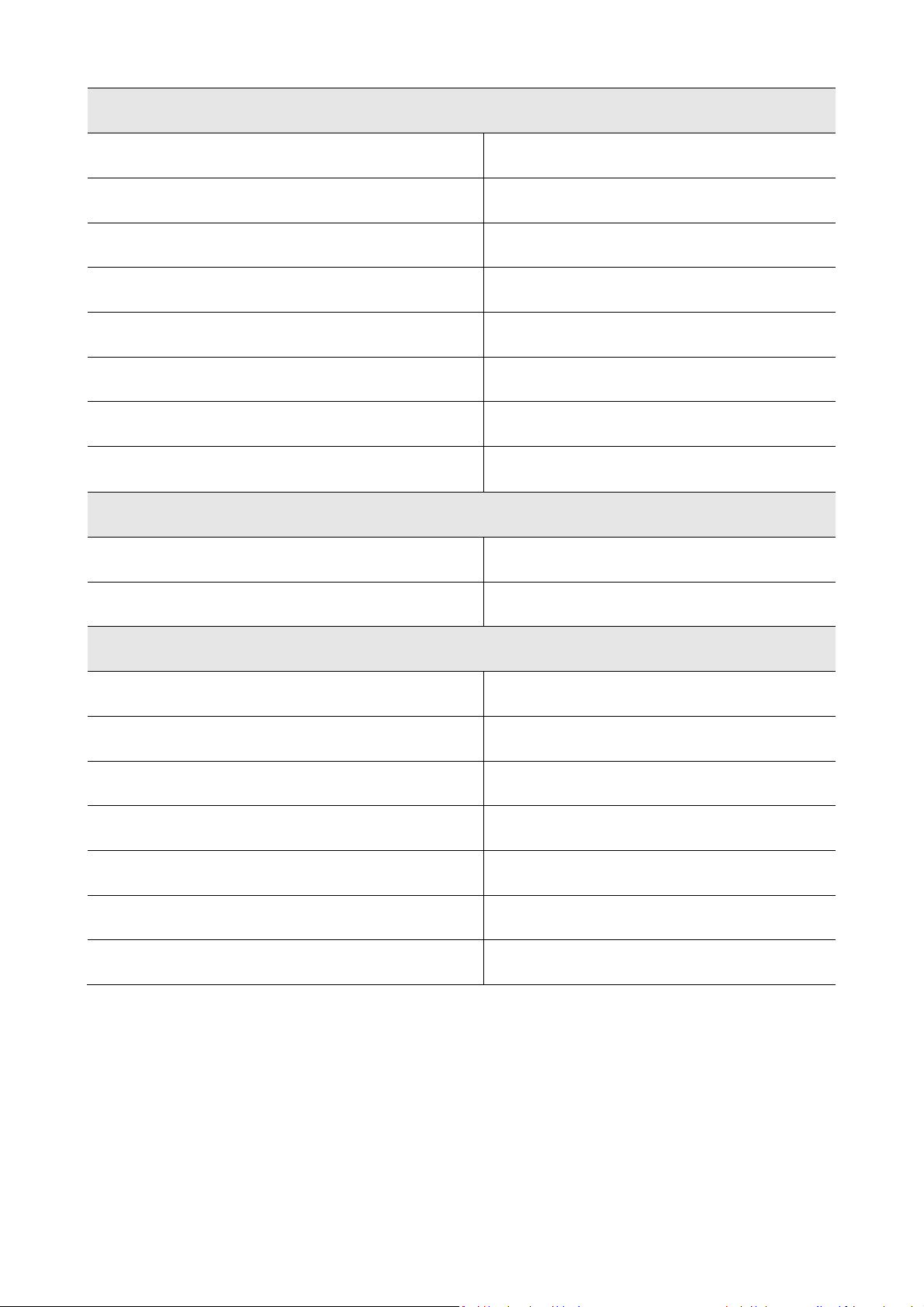
Digital outputs (electromechanical relays; A res. @ 250 VAC)
compressor 16 A
cabinet light 8 A
humidifier 8 A
dehumidifier/condenser fan 8 A
defrosting 8 A
heating elements 16 A
steam generator 8 A
pump down valve/evaporator fan
8 A
Communication port
RS-48 serial port with MODBUS communication protocol •
USB type serial port •
Other features
IP65 protection rating of the user interface IP65
clock •
signal buzzer and alarm •
management of temperature alarms •
“programs” function •
configuration parameters access password •
restoring the factory settings •
Notes:
(1) The evaporator fan control signal can be analogue or digital.
For further information, see chapter 0 15 TECHNICAL DATA; for other models contact the EVCO sales network.
Page 7 of 62
Page 8
EVCO S.p.A. EVFTFT618 | Installer manual ver. 2.2 | Code 144FTFT618E224
2 DESCRIPTION
2.1 Description of the user interface
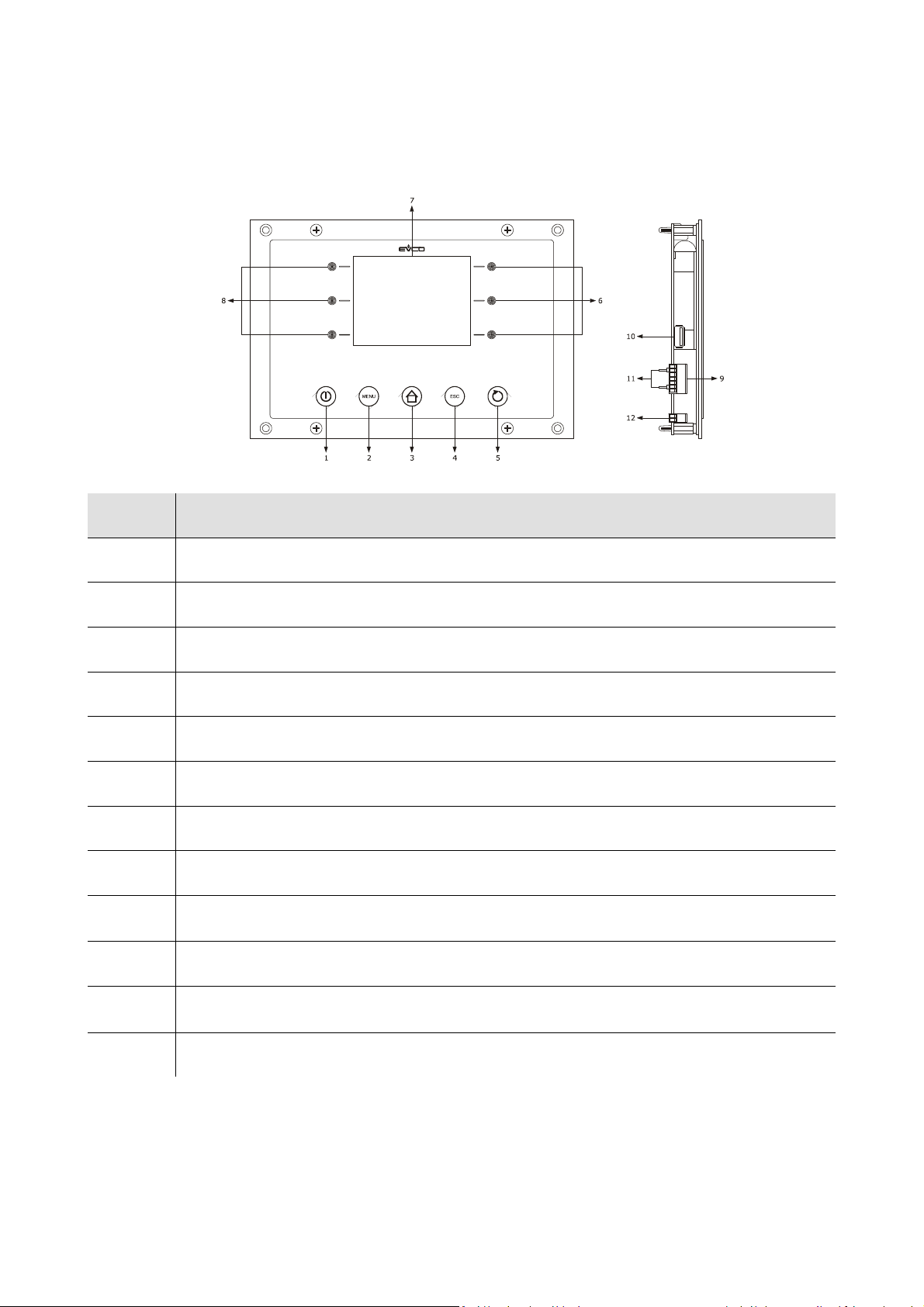
The following drawing illustrates the aspect of the EVFTFT618 user interface.
The following table illustrates the meaning of EVFTFT618 user interface parts.
Part Part
1 on/off key, herein called also "ON/STAND-BY key"
2 options key, hereon call "MENU key"
3 pre-selection key, hereon call "HOME key"
4 annul key, hereon call "ESCAPE key"
5 cycle start/cycle cut-off key, hereon called "START/STOP key"
6 interactive keys
7 display
8 interactive keys
9
10 USB type serial port
RS-485 serial port with MODBUS communication protocol and communication port with control
module (signal and power supply)
11
12 earth
For further information, see the next chapters.
jumper for the insertion of the terminating resistor of the user interface-control module
communication port and of the RS-485 serial port
Page 8 of 62
Page 9
EVCO S.p.A. EVFTFT618 | Installer manual ver. 2.2 | Code 144FTFT618E224
2.2 Description of the control module
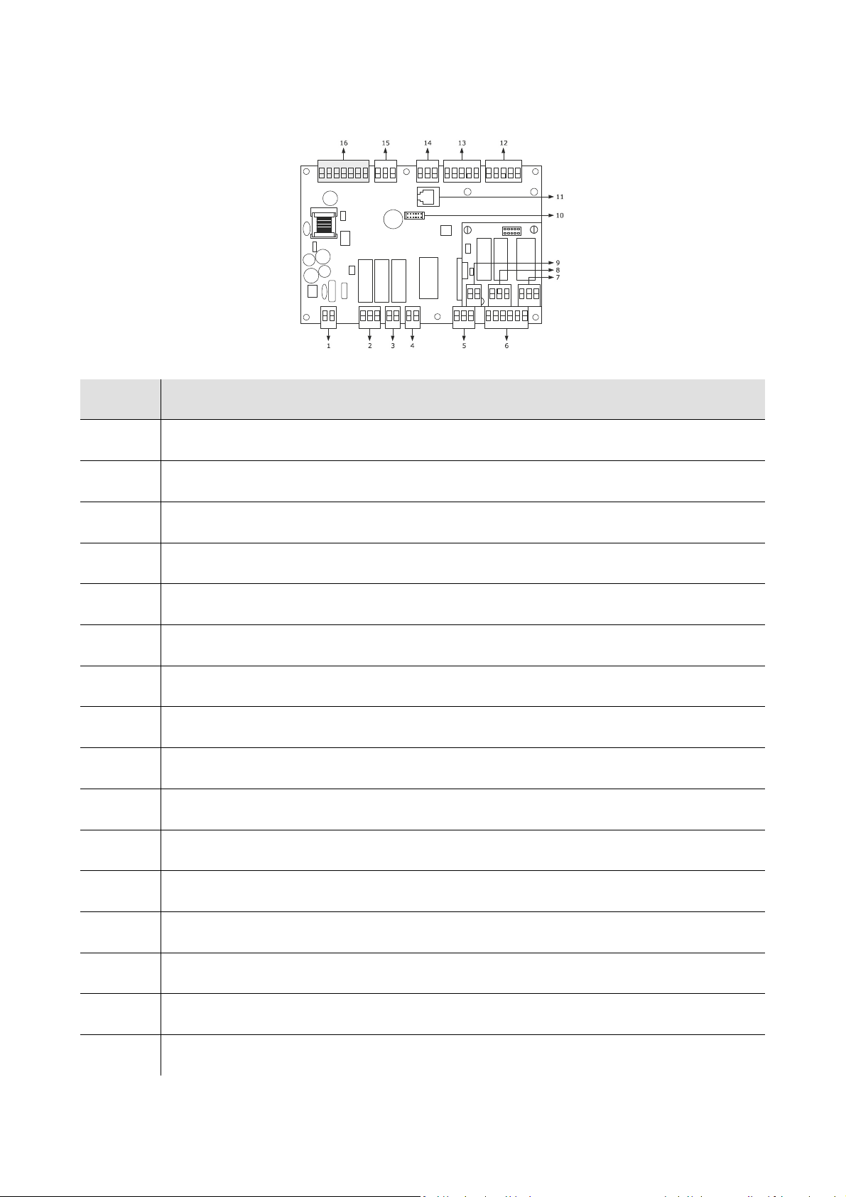
The following drawing illustrates the aspect of the EVFTFT818 control module.
The following table illustrates the meaning of EVFTFT618 control module parts.
Part Part
1 power supply
2 digital outputs K3 and K4
3 digital output K2
4 digital output K1
5 digital output K5
6 digital inputs
7 digital output K6
8 digital outputs K7 and K8
9 reserved
10 reserved
11 reserved
12 Not used
13 analogue inputs (cabinet probe, evaporator probe and condenser probe)
14 Humidity probe
15 PWM analogue output
16 communication port with the user interface (signal and power supply)
For further information, see the next chapters.
Page 9 of 62
Page 10
EVCO S.p.A. EVFTFT618 | Installer manual ver. 2.2 | Code 144FTFT618E224
partic. A
partic. A
partic. A
partic. A
175,0 (6,889)
180,0 (7,086)
200,0 (7,874)
1
1
0
,
0
(
4
,
3
3
0
)
1
2
2
,
0
(
4
,
8
0
3
)
1
3
5
,
0
(
5
,
3
1
4
)
R
2
,
0
(
0
,
0
7
8
)
1
1
6
,
0
(
4
,
5
6
6
)
1
0
8
,
0
(
4
,
2
5
1
)
1
0
0
,
0
(
3
,
9
3
7
)
8
6
,
0
(
3
,
3
8
5
)
Ø 4,0 (0,157)
Detail A
3 DIMENSIONS AND INSTALLATION
3.1 User interface dimensions
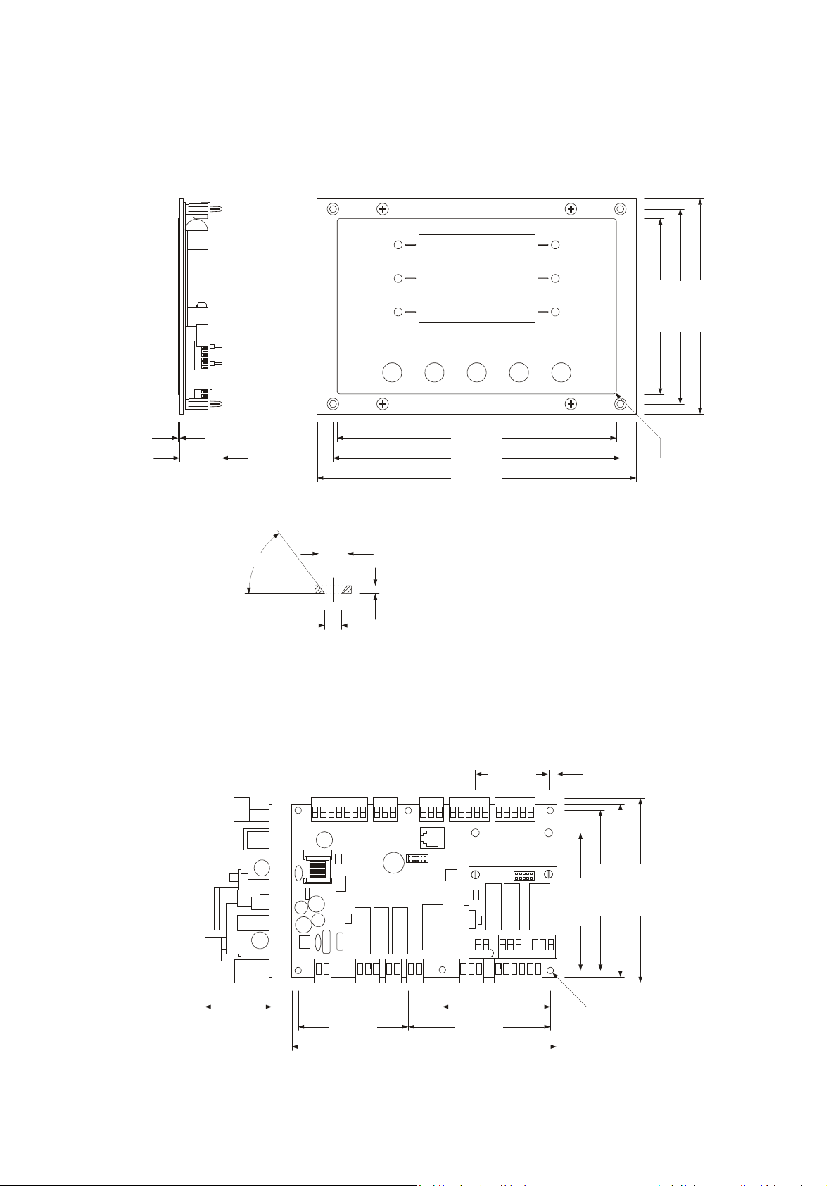
The following drawing illustrates the EVFTFT618 user interface dimensions; these are expressed in mm (in).
Det. A Det. A
Det. A Det. A
1,0 ±0,6 (0,039 ±0,023)
27,0 (1,062)
particolare A
°
3
5
4,2 (0,165)
7,2 (0,283)
2.0 (0.078)
3.2 Control module dimensions
The following drawing illustrates the EVFTFT618 control module dimensions; these are expressed in mm (in).
5,0 (0,196)46,0 (1,811)
68,0 (2,677)44,0 (1,732)
69,0 (2,716) 89,0 (3,503)
166,0 (6,535)
Page 10 of 62
Page 11

EVCO S.p.A. EVFTFT618 | Installer manual ver. 2.2 | Code 144FTFT618E224
3.3 User interface installation
Back panel via studs
3.4 Control module installation
On flat surface, with spacers.
3.5 Installation warnings
- make sure that the device work conditions (temperature of use, humidity, etc.) lie within the limits
indicated; see chapter 0 15 TECHNICAL DATA
- do not install the device near to any heat sources (heating elements, hot air ducts etc.), equipment
containing powerful magnets (large diffusers, etc.), areas affected by direct sunlight, rain, humidity, excessive dust,
mechanical vibrations or shocks.
- any metal parts in proximity of the control module must be at a distance such that they do not
compromise the safety distances; any wiring must be positioned at least 2 cm
- in compliance with Safety Standards, the device must be installed correctly and in a way to protect
against any contact with electric parts; all parts that ensure protection must be fixed in a way that they cannot be
removed without the use of tools.
Page 11 of 62
Page 12
EVCO S.p.A. EVFTFT618 | Installer manual ver. 2.2 | Code 144FTFT618E224
USB port
RS-485 port
ground
Power supply
Evaporator
humidity
cell
mains
eating
mains
Power supply
Control module
User interface
4 ELECTRIC CONNECTION
4.1 Electric connection
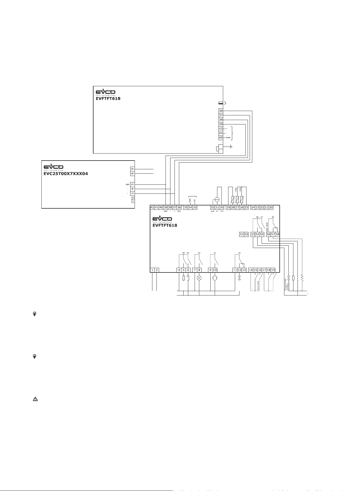
The following drawing illustrates the EVFTFT618 electric connection.
fan at
EVCFAN1
electricity
The utility managed by the K4 output, depends on parameter u3, as follows:
- dehumidifier (u3 = 0)
- condenser fan (parameter u3 = 1).
For the settings relative to the parameters, see chapter 0.
The utility managed by the K8 output, depends on parameter u1, as follows:
- pump down valve (u1 = 0, per-defined setting)
- evaporator fan (u1 = 1).
For the settings relative to the parameters, see chapter 0.
The RS-485 port is for the connection of the controller to the following additional products:
- Parameters Manager set-up software system
- RICS plants monitoring and surveillance systems
- device for recording data and to download recorded data (via USB).
The port must not be used simultaneously with more than one of these products.
electricity
Page 12 of 62
Page 13
EVCO S.p.A. EVFTFT618 | Installer manual ver. 2.2 | Code 144FTFT618E224
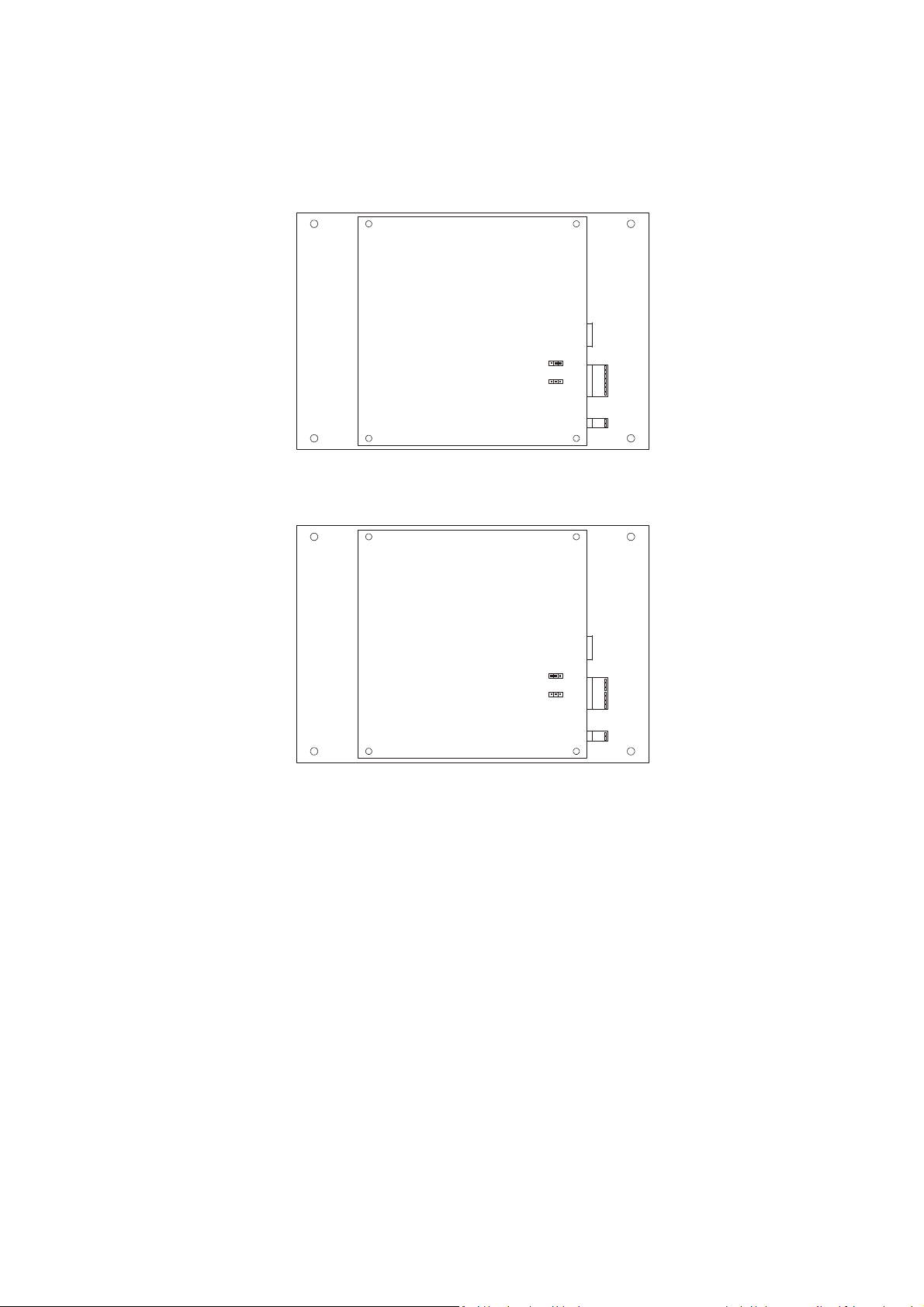
4.1.1 Connection of the terminating resistors of the communication port
The terminating resistor must be connected in order to reduce the reflections on the signal transmitted along the cables
that connect the user interface to the control model.
To connect the terminating resistors, position the jumper as illustrated in the following drawing.
To disconnect the terminating resistors, position the jumper as illustrated in the following drawing.
Page 13 of 62
Page 14
EVCO S.p.A. EVFTFT618 | Installer manual ver. 2.2 | Code 144FTFT618E224
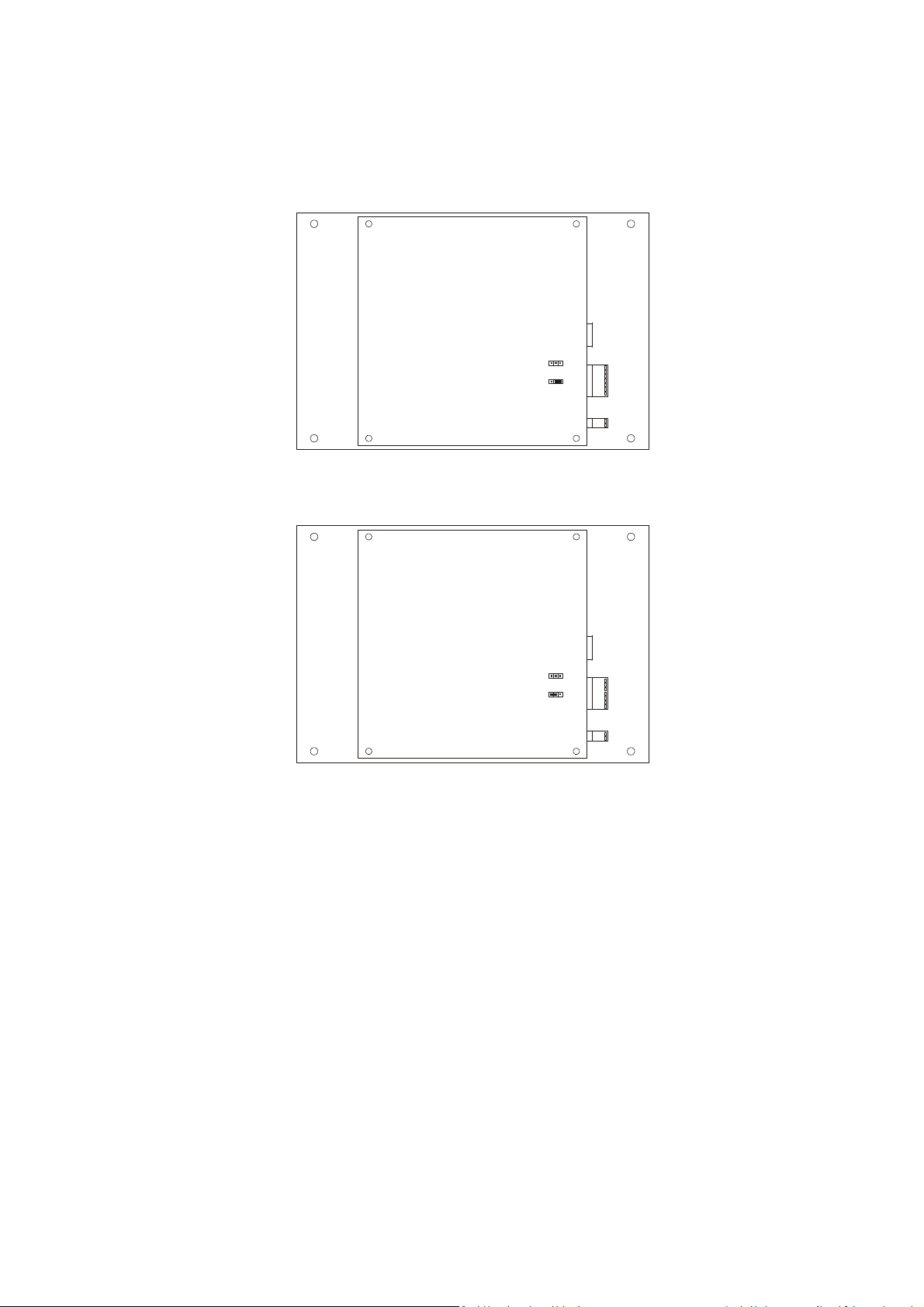
4.1.2 Connection of the RS-485 serial port terminating resistor
The terminating resistor must be connected in order to reduce the reflections on the signal transmitted along the cables
that connect the RS-485 serial port to other EVCO products.
To connect the terminating resistors, position the jumper as illustrated in the following drawing.
To disconnect the terminating resistors, position the jumper as illustrated in the following drawing.
4.2 Warnings for the electric connection
- do not use electric or pneumatic screwdrivers on the device terminal board
- if the device has been taken from a cold to hot place, humidity could condense inside; wait about 1 hour before
powering it
- make sure that the power supply voltage, the frequency and the operational electric power of the device,
correspond with those of the local power supply; see chapter 0
- disconnect the device power supply before proceeding with any type of maintenance
- do not use this device as a safety device
- for repairs and information regarding the device, contact the EVCO sales network.
Page 14 of 62
Page 15
EVCO S.p.A. EVFTFT618 | Installer manual ver. 2.2 | Code 144FTFT618E224
5 USER INTERFACE
5.1 Preliminary notes
The following operating status exist:
- the “stand-by” status (the device is powered and is off)
- the “on” status (the device is powered, is on and is in stand-by for the start-up of an operating cycle)
- the “run” status (the device is powered, is on and an operating cycle is in progress).
Hereon, the term "device switch-on" means the passage from the "stand-by" status to the "on" status. the term "switch-
off" means passage from the "on" status to the "stand-by" status.
If a power cut occurs during the "stand-by" status or during the "on" status, the device will re-propose the same status
when the power supply is restored.
If a power cut occurs during the "run" status, the device will operate as follows when this is restored:
operation after cut-off of the power supply depends on parameter "P6"; if set at 0 the cycle will be interrupted, if set at 1
the cycle will be re-started and if set at 2 the cycle will only be re-started if the the power cut-off supply was less than the
time set by parameter "P5".
5.2 Device commissioning
Operate as follows:
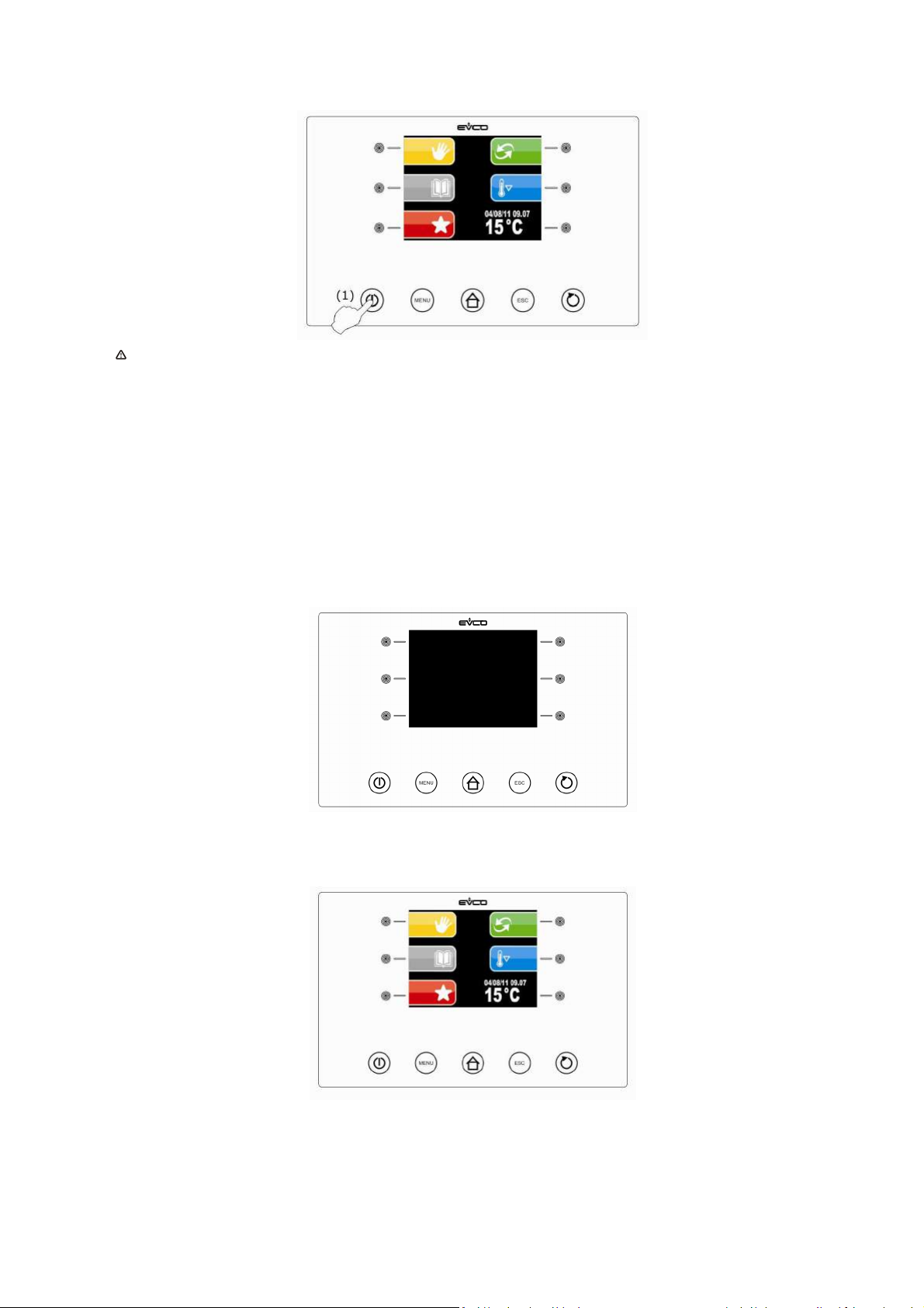
1. Connect the device power supply. if parameter E9 is set at 1, the device will display the EVCO splash screen for 10
seconds, otherwise it will display a black screen for 10 seconds, after which it will go to the STANDBY status.
Page 15 of 62
Page 16
EVCO S.p.A. EVFTFT618 | Installer manual ver. 2.2 | Code 144FTFT618E224
2. Press and release the ON/STAND-BY (1) key.
If the duration of power supply cut-off was such to cause the clock error, the board will display the clock setting
screen directly. The controller does not control the coherence of the data entered, it is the user's job to control
the data are entered correctly.
5.3 Switching the Device On/Off
Operate as follows:
1. Press and release the ON/STAND-BY key.
5.4 The display
The display will be off during the STANDBY status. The LEDs relative to the active keys are on.
During the ON status, the device will display the date, real time, cabinet temperature and the possible functions that can
be selected.
Page 16 of 62
Page 17
EVCO S.p.A. EVFTFT618 | Installer manual ver. 2.2 | Code 144FTFT618E224
CYCLE END
MACHINE STOP
6. OPERATION
6.1 Preliminary notes
The controller supplies a complete control for retarder-proofer cabinets or cells for confectionery and bread-making,
through the automatic management of the complete mixture retarder-proofer cycle.
MACHINE
START
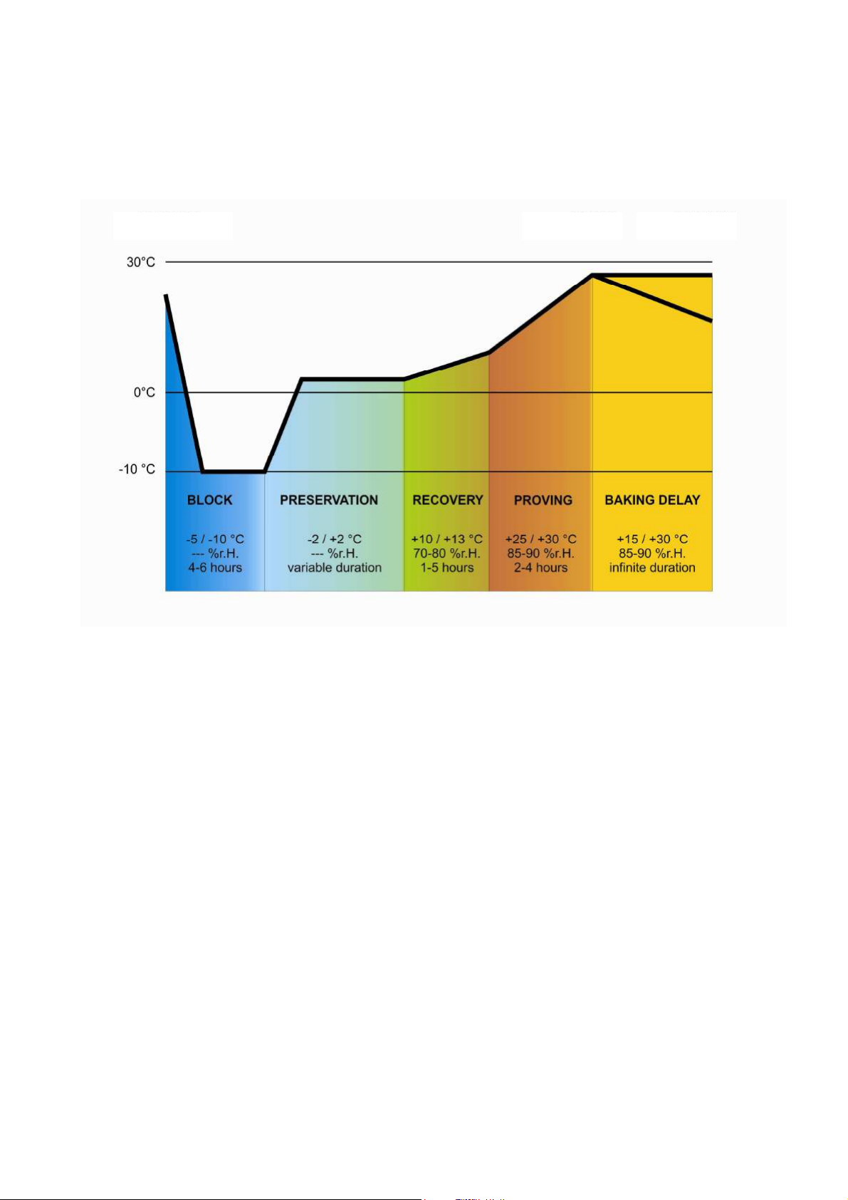
An automatic retarder-proffer cycle is composed of 5 different phases with different temperatures, relative humidity, fan
speed and duration, which are performed one after the other and precisely:
1. BLOCK phase
The block phase is the first phase of the automatic cycle.
Temperature regulation is active and is neutral area, the temperature set-point, the humidity set-point (the control if
envisioned), the speed of the fans and the duration in hours and minutes of the phase are established by the final user.
Adjustment of the relative humidity depends on parameter rU4. If set at zero, humidity control is not envisioned in this
phase.
2. STORAGE phase
The storage phase is the second phase of the automatic cycle.
Temperature regulation is active and is neutral area, the temperature set-point, the humidity set-point (the control if
envisioned), the speed of the fans and are established by the final user.
Adjustment of the relative humidity depends on parameter rU4. If set at zero, humidity control is not envisioned in this
phase.
The duration of this phase is calculated automatically by the controller on the basis of the duration of the lock, recovery,
proving phases and the day and time of proving end time desired for the mixture.
3. RECOVERY phase
The recovery phase is the third phase of the automatic cycle.
The temperature regulation is active and is NEUTRAL AREA, the work set-point is established by the final user. The
passage from the storage set-point (previous phase) to the recovery set-point can be gradual with increase percentages
established in the parameters programming phase.
The relative humidity regulation is active and is NEUTRAL AREA, the work set-point is established by the final user.
The duration in hours and minutes of the phase and the evaporator fan speed are established by the final user.
Page 17 of 62
Page 18

EVCO S.p.A. EVFTFT618 | Installer manual ver. 2.2 | Code 144FTFT618E224
4. PROVING phase
The proving phase is the fourth phase of the automatic cycle.
The temperature regulation is active and is NEUTRAL AREA, the work set-point is established by the final user. The
passage from the recovery set-point (previous phase) to the proving set-point can be gradual with increase percentages
established in the parameters programming phase.
The relative humidity regulation is active and is NEUTRAL AREA, the work set-point is established by the final user.
The duration in hours and minutes of the phase and the evaporator fan speed are established by the final user.
5. BAKING DELAY phase
The baking delay phase is the fifth phase of the automatic cycle.
The baking delay phase is always disabled but can be enabled both in the cycle setting phase and also with cycle in
progress by the final user.
The temperature regulation is active and is NEUTRAL AREA, the work set-point is established by the final user.
The relative humidity regulation is active and is NEUTRAL AREA, the work set-point is established by the final user, as is
the evaporator fan speed.
The duration of the phase is theoretically infinite, i.e. it ends when the cycle is interrupted by pressing the stop key for 3
seconds.
There are also 2 manual work cycles available; one MANUAL REFRIGERATION cycle (equivalent to a storage but with
infinite duration) and a MANUAL HEATING cycle (equivalent to a proving cycle with infinite duration and without regulation
steps).
To make these regulations possible, the controller will therefore manage the utilities set-up for cooling (compressor,
evaporator fan, defrosting, pump-down electrovalve), for heating (heating elements or operating in heat pump mode),
humidification (steam generator, humidifier) end dehumidification (dehumidification via extraction fan or via activation of
the cooling plant); the regulations of each individual utility will be described in the following chapters.
In addition to management of the automatic and manual cycles, the controller envisions the possibility to manage other
functions, such as:
- Pre-cooling management
- "Delayed baking" connection/disconnection management
- Cabinet light management
- Management of 10 user programs
- Management of 10 Favourite Programs
- Connection to RICS
- Host USB port management on machine for: download/upload PROGRAMS, download/upload PARAMETERS and
download HACCP data.
Page 18 of 62
Page 19
EVCO S.p.A. EVFTFT618 | Installer manual ver. 2.2 | Code 144FTFT618E224
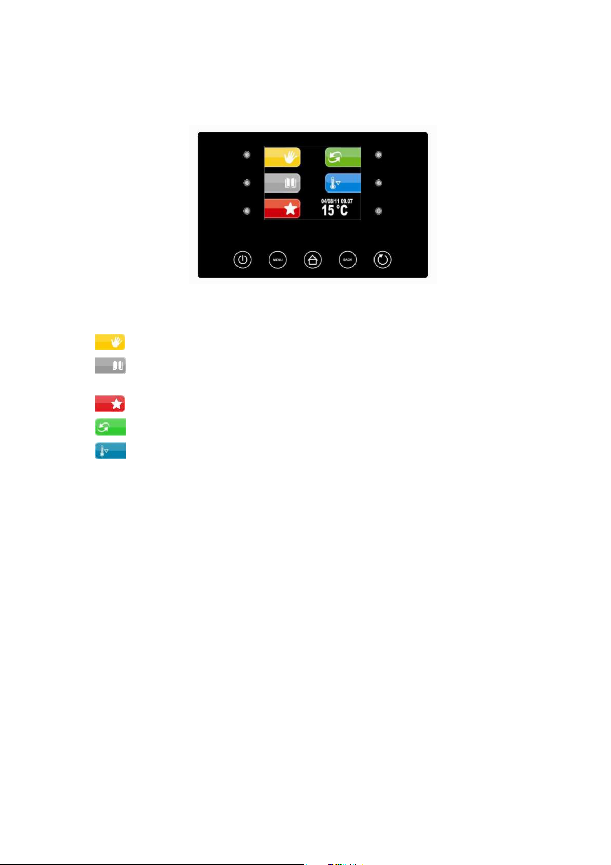
6.1.1 Pre-selection page
The Pre-selection page represents the "start point" foe navigating the user interface.
The functions enabled and the dates data, time and temperature in cabinet are present in the pre-selection page.
All final user selections will start from the pre-selection page.
The 5 “interactive” keys will allow to select:
- MANUAL: i.e. selection, setting and running a manual cooling or heating cycle.
- PROGRAMS: i.e. the selection and/or modification of automatic retarder-proffer cycles saved in the
memory
- FAVOURITES: i.e. the quick recall of the last 10 performed.
- AUTOMATIC: i.e. the selection, setting and execution of a complete automatic retarder-proofer cycle.
- PRE-COOLING: i.e. the execution of a cabinet pre-cooling cycle
The 2 active “navigation” keys will allow to select:
- ON/STANDBY to take the machine back to STANDBY status
- MENU to access the pre-selection page options screen
Page 19 of 62
Page 20
EVCO S.p.A. EVFTFT618 | Installer manual ver. 2.2 | Code 144FTFT618E224
Manual Refrigeration/Hea
ting screen
the options menu.
Refrigeration
List of AI, DI, AO, DO, SET values
for display (see dedicated
REAL TIME DISPLAY
By pressing one of the 3 keys on the LEFT, select a Cooling cycle, pressing those
d fan speed. Humidity setting display
is subject to humidity control in the cycle requested. Speed setting visibility is subject to
Refrigeration
Heating
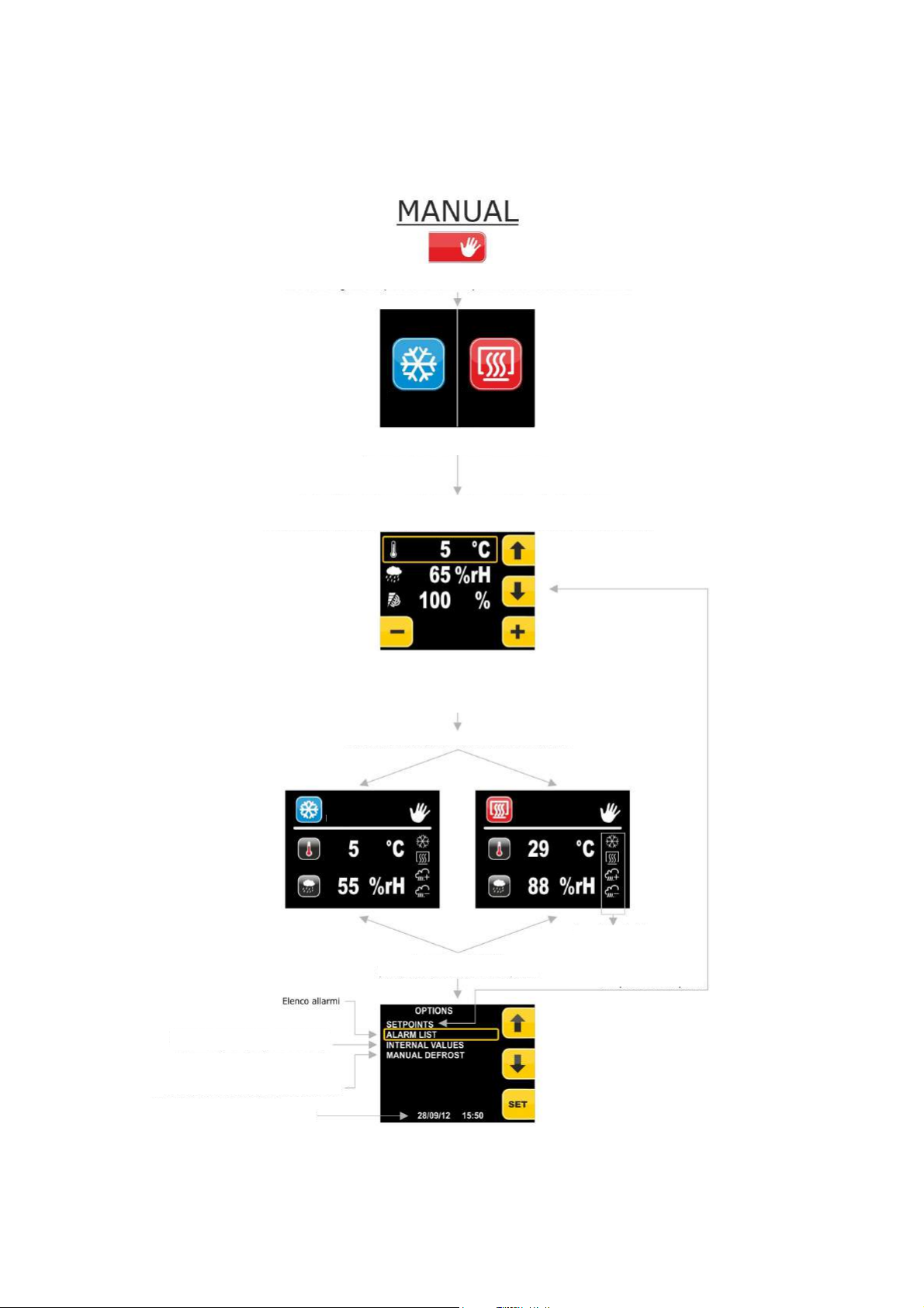
6.1.2 Setting and execution of a manual cycle
Below the complete navigation system of the MANUAL menu is illustrated.
From this menu it is possible to select and perform a complete manual COOLING or HEATING cycle.
To reach the MANUAL menu from the pre-selection page, press the key at the side of the MANUAL icon:
Selecting the MANUAL menu allows to set a refrigeration (heating prohibited)
cycle or heating cycle with infinite duration
on the RIGHT, a Heating cycle.
Page for setting temperature set-point, humidity an
management of the fan speed.
Pressing the UP/DOWN keys will change the e set-point to set. Pressing the +/- keys will
change the value of the set-point selected.
Pressing Home and Back are activated.
Pressing STAND-BY is deactivated
Pressing START starts the cycle
Pressing MENU slows to access
Heating
Main outputs
status bar
Access to the set-points
setting screen
Manual Defrosting
Press the START/STOP key to start the cycle. Press the START/STOP key for 3 seconds to interrupt the cycle.
Page 20 of 62
Page 21
EVCO S.p.A. EVFTFT618 | Installer manual ver. 2.2 | Code 144FTFT618E224
From this screen it is possible to scroll all
individual data of the pertinent phase, select the
The instrument proposes the first possible hour and the first day
will be possible to access the recipes save page,
Once the desired values have been modified via
to the initial screen or the UP key to pass to the
next page
In this screen it is possible to modify the cycle end time by pressing
On this screen it is possible to give the desired name to
the program, thanks to the save as option. The name can
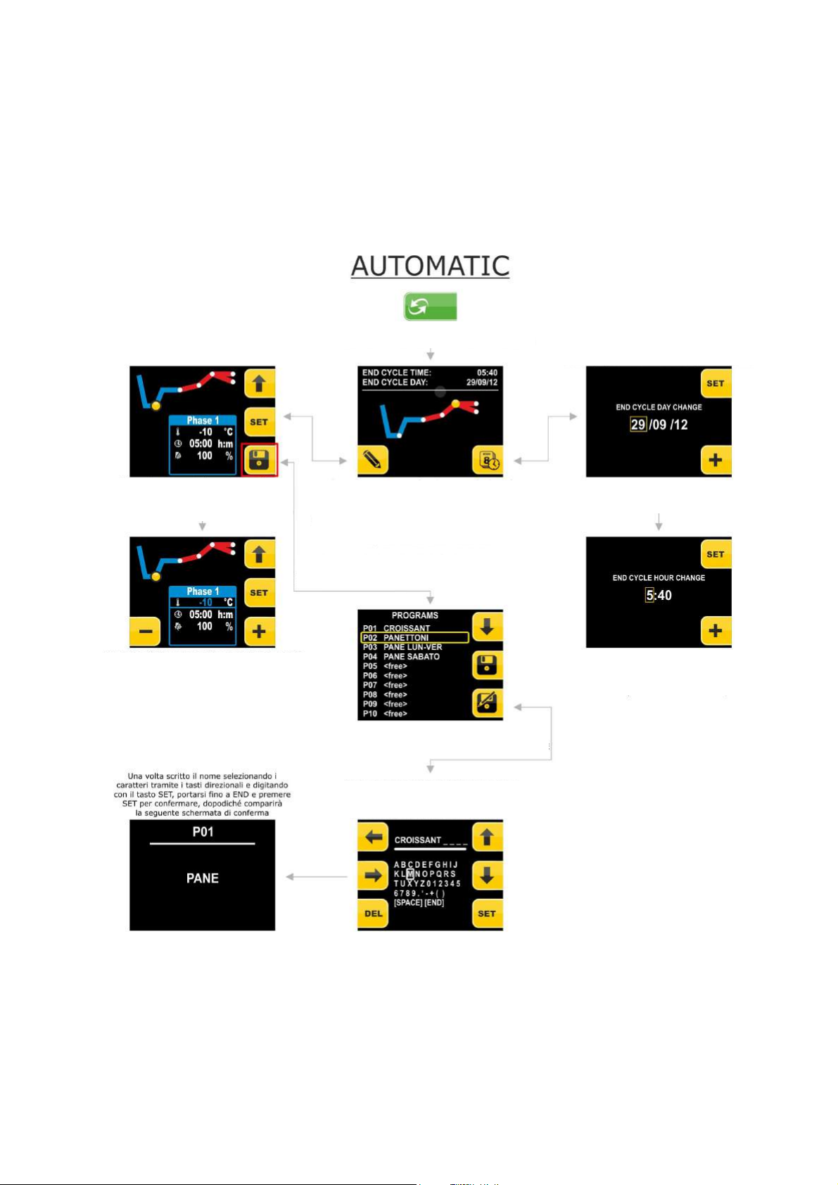
6.1.3 Setting an automatic cycle
Below the complete navigation system of the AUTOMATIC menu is illustrated.
It is the real "heart" of the product as all retarder-proofer cycles will be set from this menu and the PROGRAMS and
FAVOURITES menus will be passed on once the saved cycles have been selected.
From this menu it will also be possible to save the cycle set before its execution (from the 10 programs available).
To reach the AUTOMATIC menu from the pre-selection page, press the key at the side of the AUTOMATIC icon:
cycle phases using the UP key
In this screen it is possible to modify each
desired value by pressing the SET button
repeatedly until the desired data
the + and- keys, press the BACK key to return
Selection of the AUTOMATIC menu allows to set
a complete retarder-proofer cycle
for cycle end on the basis of the times set in the phases (i.e. the
cycle end time with phase 2 duration 0). It is possible to modify
both the date and time of cycle end and modify the cycle set
completely in all phases. From this screen it is possible to start
the cycle by pressing the START/STOP key.
On completion of customization of all phases, it
by pressing the save key.
In this screen it is possible to modify the cycle
end date by pressing the + key, it can only be
Once the date has been set, press SET to pass
to modification of the time or the START/STOP
program with a name already present in the
modified day by day
key to start the cycle
In this screen it is possible to save the
list via the SAVE key or create a new
program via the SAVE AS key
Once the time has been modified, the cycle can be started by
be composed of a maximum of 15 characters
the + key.
pressing the START/STOP key.
Page 21 of 62
Page 22
EVCO S.p.A. EVFTFT618 | Installer manual ver. 2.2 | Code 144FTFT618E224
key allows to enable/disable
Main outputs status bar
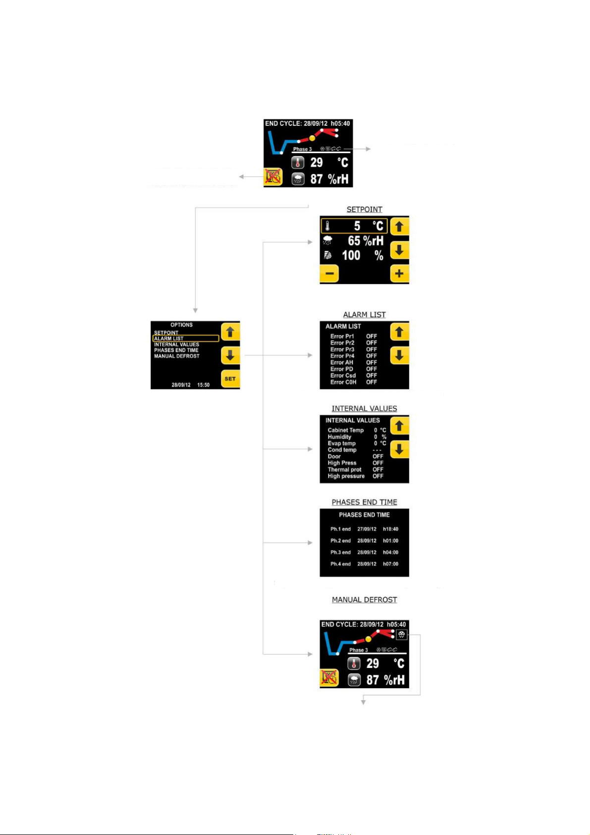
In this screen it is possible to display the active alarms and
In this screen it is possible to modify the set
-
points. Scroll the set
-
points
In this screen it is possible to display the time at which each phase ends
Item p
resent only during the phases in which the
Once manual defrosting is pressed, the same will
The internal values can be displayed on this screen
6.1.4 Execution of an automatic cycle
Below find the illustration of the complete navigation system during the execution of an automatic cycle.
Once the automatic cycle is started, the following screen is displayed:
The BAKING DELAY
phase 5 of the cycle during execution
By pressing the MENU key, reach the OPTIONS
screen
to be modified using the UP and DOWN keys and proceed with the
modification using the + and - keys. Once the modification has been
completed, press BACK to return to the menu
non-active alarms
possibility of activation is envisioned
start. The defrost symbol will appear in the cycle in
progress window.
Press the START/STOP key to start the cycle. Press the START/STOP key for 3 seconds to interrupt the cycle.
Page 22 of 62
Page 23
EVCO S.p.A. EVFTFT618 | Installer manual ver. 2.2 | Code 144FTFT618E224
Selection o
f the PROGRAMS menu allows to select a
ailable. Once the desired program has
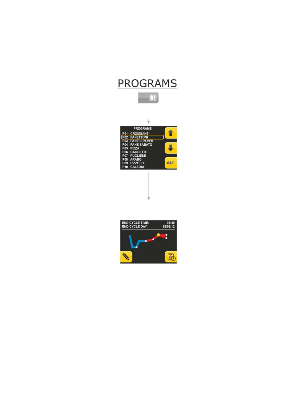
6.1.5 The PROGRAMS menu
Below the complete navigation system of the PROGRAMS menu is illustrated.
This menu allows to select the program to be performed and/or modified. Once selected, press the SET key. In this way
the choice is confirmed and passes to the AUTOMATIC menu.
To reach the PROGRAMS menu from the pre-selection page, press the key at the side of the PROGRAMS icon:
retarder-proofer cycle from the 10 programs available
Use the UP and DOWN keys to scroll the programs av
been highlighted, press the SET key to confirm. The program selected will be re-proposed
will all settings in the first automatic cycle selection screen, i.e. with the selection of end
cycle time and date.
From this point, the cycle start-up and setup
management will be the same as those of
automatic cycle setting.
If the program selected is not present, pressing the SET key will have no effect.
6.1.5.1 Modify Date and Time of Automatic Cycle End
The program end day can be moved up to 20 days after. The MINUS key only appears of the
day is modified, otherwise it is not visible as the date that is proposed is the first possible with the settings present.
Page 23 of 62
Page 24
EVCO S.p.A. EVFTFT618 | Installer manual ver. 2.2 | Code 144FTFT618E224
of the FAVOURITES menu allows the quick selection
vailable. Once the desired program has
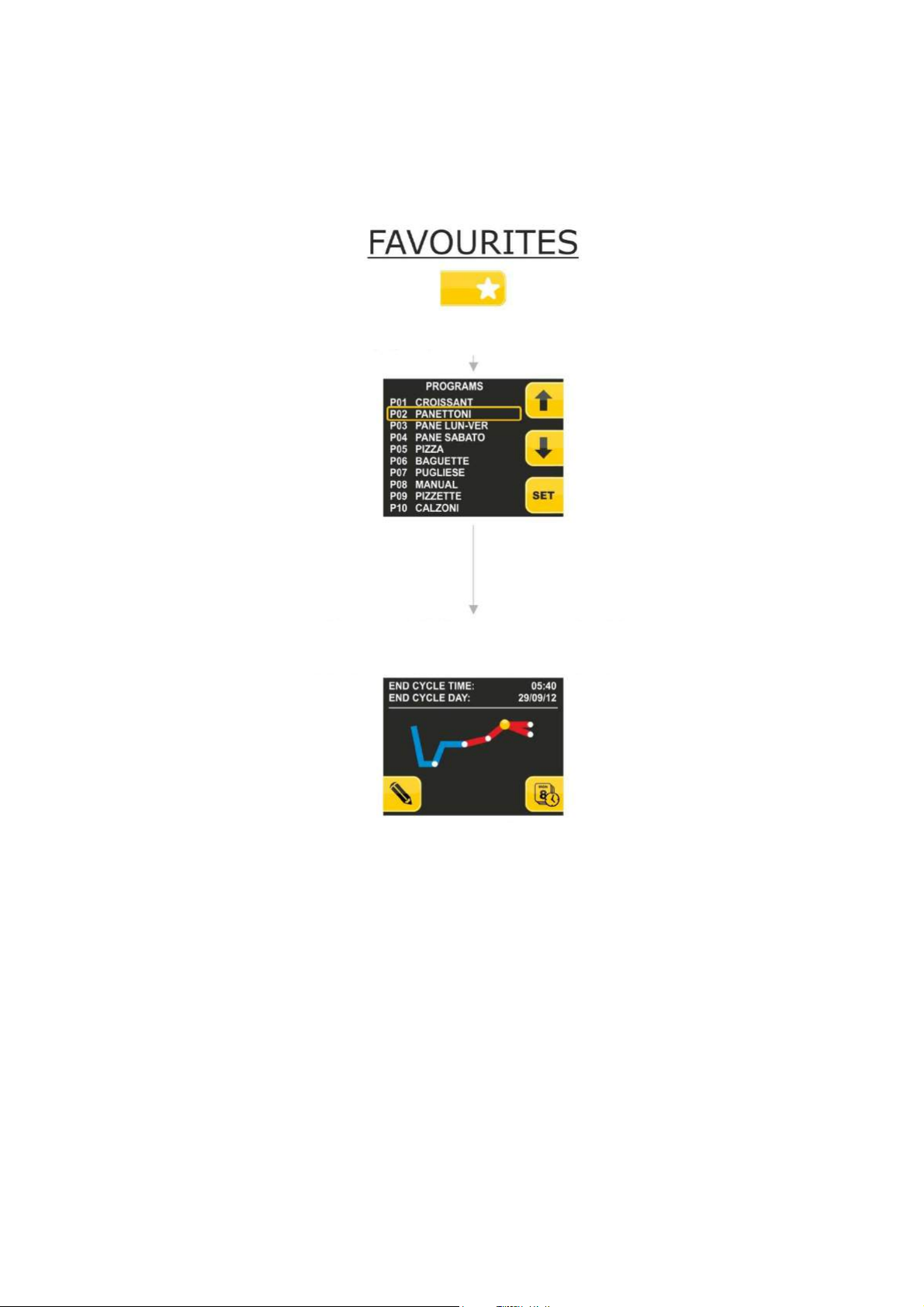
6.1.6 The FAVOURITES menu
Below the complete navigation system of the FAVOURITES menu is illustrated.
This menu has the purpose of quickly recalling the "favourites" cycles, i.e. the last 10 cycles performed by the machine.
To reach the FAVOURITES menu from the pre-selection page, press the key at the side of the FAVOURITES key:
Selection
of one of the last 9 cycle performed, whether they be
programs, automatic cycles or manual cycles
Use the UP and DOWN keys to scroll the programs a
been highlighted, press the SET key to confirm. The program selected will be re-proposed
will all settings in the first automatic cycle selection screen, i.e. with the selection of end
From this point, the cycle start-up and setup
management will be the same as those of automatic
cycle time and date.
cycle setting
The selection of a program with hyphens is not allowed. Pressing the set key has no effect.
Page 24 of 62
Page 25
EVCO S.p.A. EVFTFT618 | Installer manual ver. 2.2 | Code 144FTFT618E224
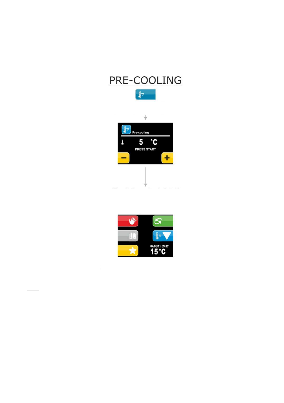
COOLING MENU allows to activate a
cooling function in the main screen
(flashing) to indicate that
6.1.7 The PRE-COOLING menu
Below the complete navigation system of the PRE-COOLING menu is illustrated.
This menu allows to activate pre-cooling of the cabinet while waiting to select a retarder-proofer
cycle.
To reach the PRE-COOLING menu from the pre-selection page, press the key at the side of the PRE-COOLING icon:
Selection of the PRE-
pre-cooling while waiting for a retarder-proofer cycle to
be selected
Use the + and – keys to set the desired pre-cooling setpoint; use the START button to start the machine up.
The cycle has infinite duration until a program is
launched. When the first work set-point is reached, the
controller will emit an acoustic signal
The key that indicates the pre-
will have the additional cooling symbol
the pre-cooling function is in progress
Note: a cycle can be launched at any time during pre-cooling.
Page 25 of 62
Page 26
EVCO S.p.A. EVFTFT618 | Installer manual ver. 2.2 | Code 144FTFT618E224
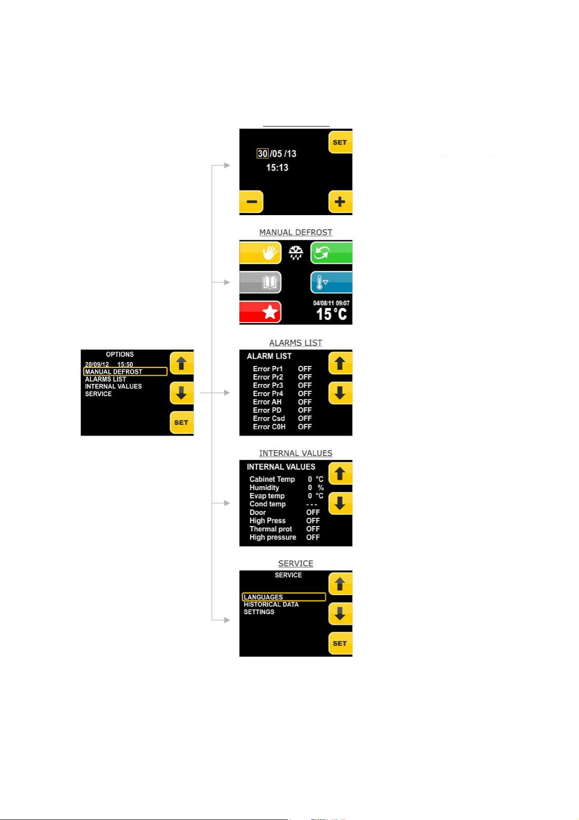
In this screen it is possible to display the active alarms and
The internal states can be displayed on this screen
For the SERVICE menu, see the next paragra
ph
DATE AND HOUR
6.1.8 The PRE-SELECTION PAGE OPTIONS menu
Below the complete navigation system of the FAVOURITES menu is illustrated.
To reach the PRE-SELECTION PAGE OPTIONS menu from the pre-selection page, press the MENU key.
In this screen it is possible to set the date and time. Press
SET to select the value to set using the + and- keys. Once
set press BACK to return to the menu
By selecting MANUAL DEFROST, go back to the main page
where the defrost icon will appear, indicating the manual
defrost cycle I in progress.
non-active alarms
Page 26 of 62
Page 27
EVCO S.p.A. EVFTFT618 | Installer manual ver. 2.2 | Code 144FTFT618E224
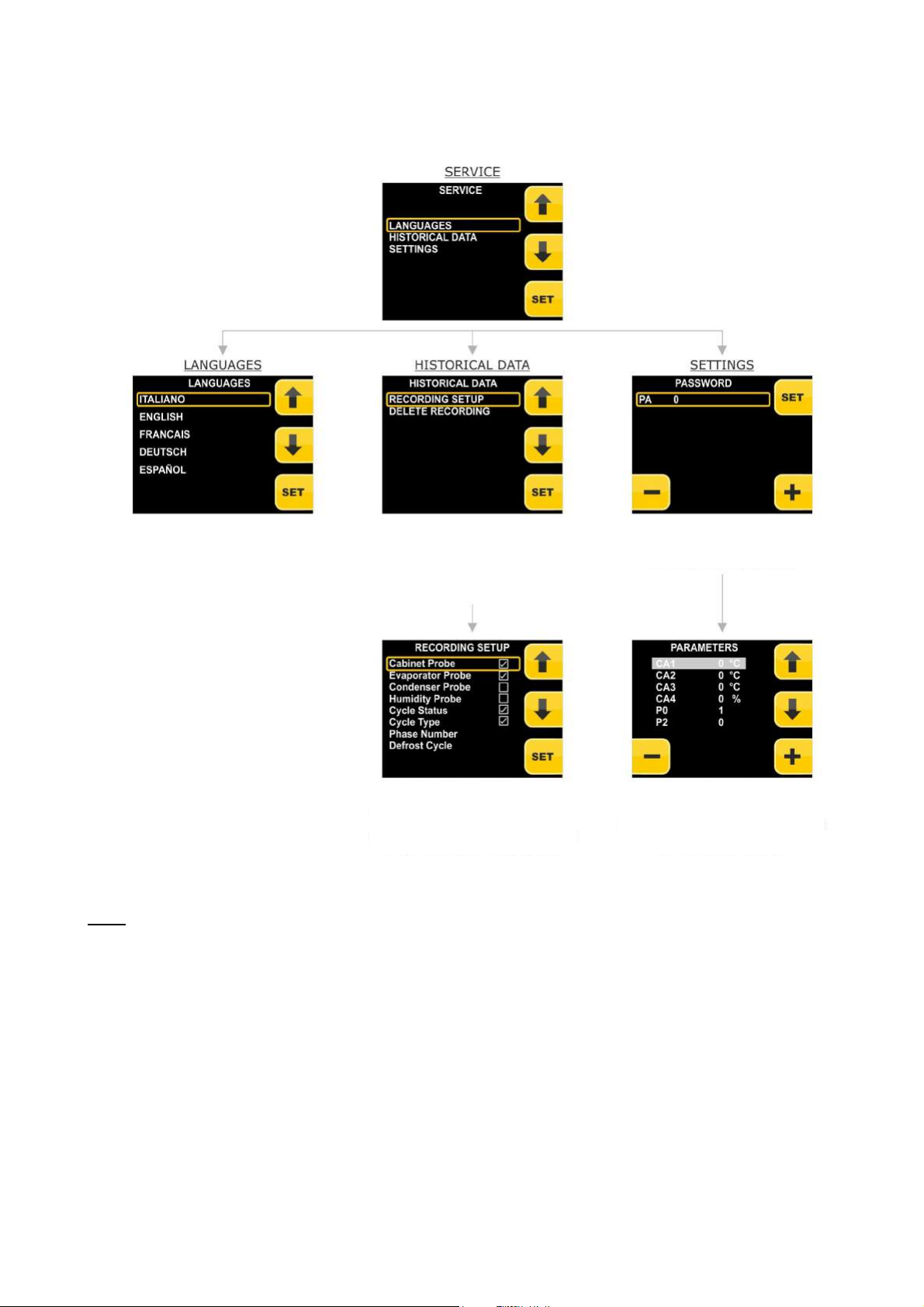
DELETE RECORDING, it will be possible to delete
list of variables. Press set to select/unselect
saved
6.1.8.1 The SERVICE menu
Select the language using the UP and DOWN
keys and SET to confirm
SETUP RECORDING allows to access a screen
which will allow to select which variables to
record in the historic data TXT file. By selecting
the entire data log (procedure protected by
Press the UP and DOWN keys to scroll the
the control boxes. (The value will be
when the next variable is selected).Press
password 149)
BACK to escape
Press the SET key to confirm the value of the
password set (the password is -19) and access
Press the UP and DOWN keys to scroll the
value will be saved when the next variable
the parameters menu
list of parameters. + or – to change the
value at the pre-selected parameter (the
is selected). Press BACK to exit
Note: if the language is modified, all programs memorised (favourites) will be deleted and those customised (default) will
be taken back to the pre-established values.
Page 27 of 62
Page 28
EVCO S.p.A. EVFTFT618 | Installer manual ver. 2.2 | Code 144FTFT618E224
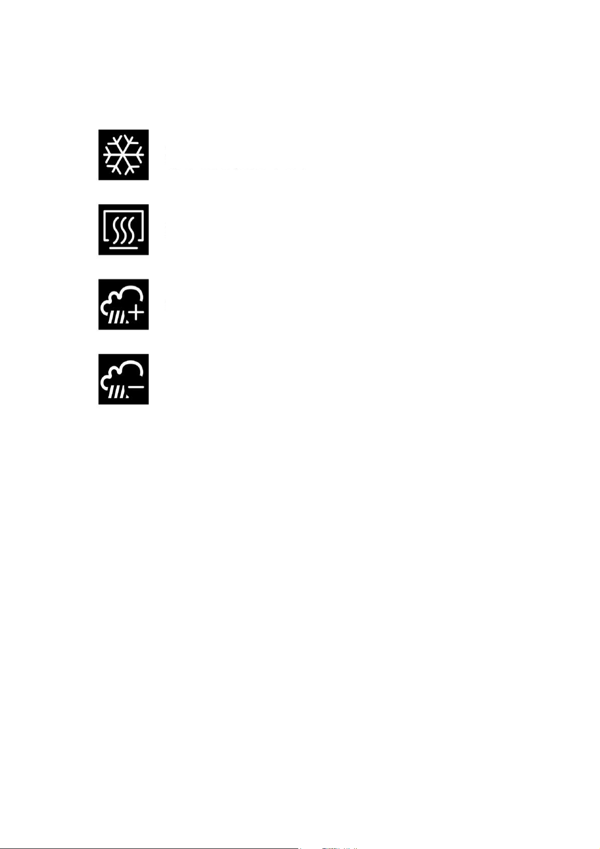
White light on indicates the compressor is active
7 Detail Meaning Icons Status Regulators
During the execution of a cycle (both manual and automatic) the states of the main utilities are displayed through the
icons.
Yellow light on indicates the request for compressor activation but safety times not yet expired
Off means compressor is not active
On indicates heating active
Off indicates heating not on
On indicates humidification active
Off indicates humidification not on
On indicates dehumidification active
Off indicates dehumidification not on
7.1 Silencing the buzzer
Press and release any key when the buzzer is ringing. If the buzzer rings to end an automatic cycle or for
pre-cooling temperature reached, as well as by pressing the key, the button also deactivates after the seconds defined by parameter E12.
8 Keyboard lock
The keyboard lock can be managed in manual and automatic mode, the method of use must be set with parameter E8.
8.1 Manual keyboard lock
In this case, to lock and unlock the keyboard it is necessary to press the HOME key for 3 seconds.
8.2 Automatic keyboard lock
In this case, the keyboard will lock after 1 minute of inactivity during the cycle. The HOME key must be pressed for 3
seconds to unlock it.
Page 28 of 62
Page 29
EVCO S.p.A. EVFTFT618 | Installer manual ver. 2.2 | Code 144FTFT618E224
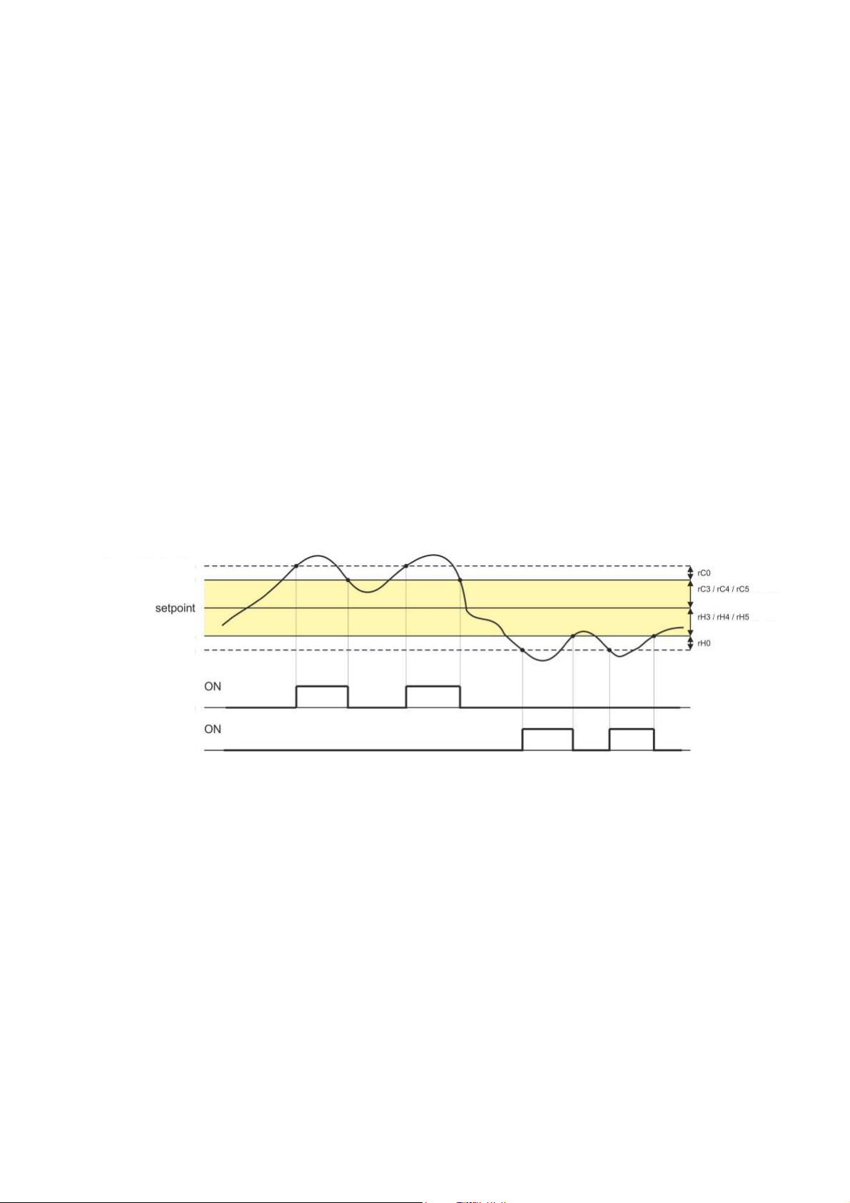
Cooling differential
cold
9 Regulations
9.1 Pre-cooling
The pre-cooling cycle has the purpose of taking the cabinet to a determined temperature before selecting and performing
a retarder-proofer cycle.
During the pre-cooling cycle, the compressor, condenser fans, the pump-down electrovalve (if enabled) and the
evaporator fan work to reach the temperature established.
Once the pre-cooling temperature has been reached, the buzzer rings intermittently to indicate that the machine is ready
to perform a cycle. The buzzer is silenced by pressing any key or after the time defined by parameter E11.
The pre-cooling cycle continues until the START/STOP key is pressed or until an automatic or manual cycle is started by
the user.
9.2 Temperature regulation
The temperature regulation for all machine phases is with neutral area.
Meaning with a work set-point and a neutral area within which activations of loads set-up for heating or cooling do not
take place.
When the temperature goes above the neutral area value of the cooling differential value, the utilities set-up for cooling
will be activated until the temperature returns within the neutral area value.
In the same way, when the temperature goes below the neutral area value of the heating differential value, the utilities
set-up for heating will be activated until the temperature returns within the neutral area value.
Cooling neutral area
(depending on the phase)
Heating neutral area
(depending on the phase)
Heating differential
hot
9.2.1 Generating cold
The generation of the cold refers to the cooling circuit installed on the machine.
During a cooling request, the compressor output will be activated along with the pump-down electro valve (if enabled).
The evaporator fan will go in continuous mode or parallel to the compressor on the basis of that established for each
parameters configuration phase and at the speed established for the phase in progress.
Page 29 of 62
Page 30
EVCO S.p.A. EVFTFT618 | Installer manual ver. 2.2 | Code 144FTFT618E224
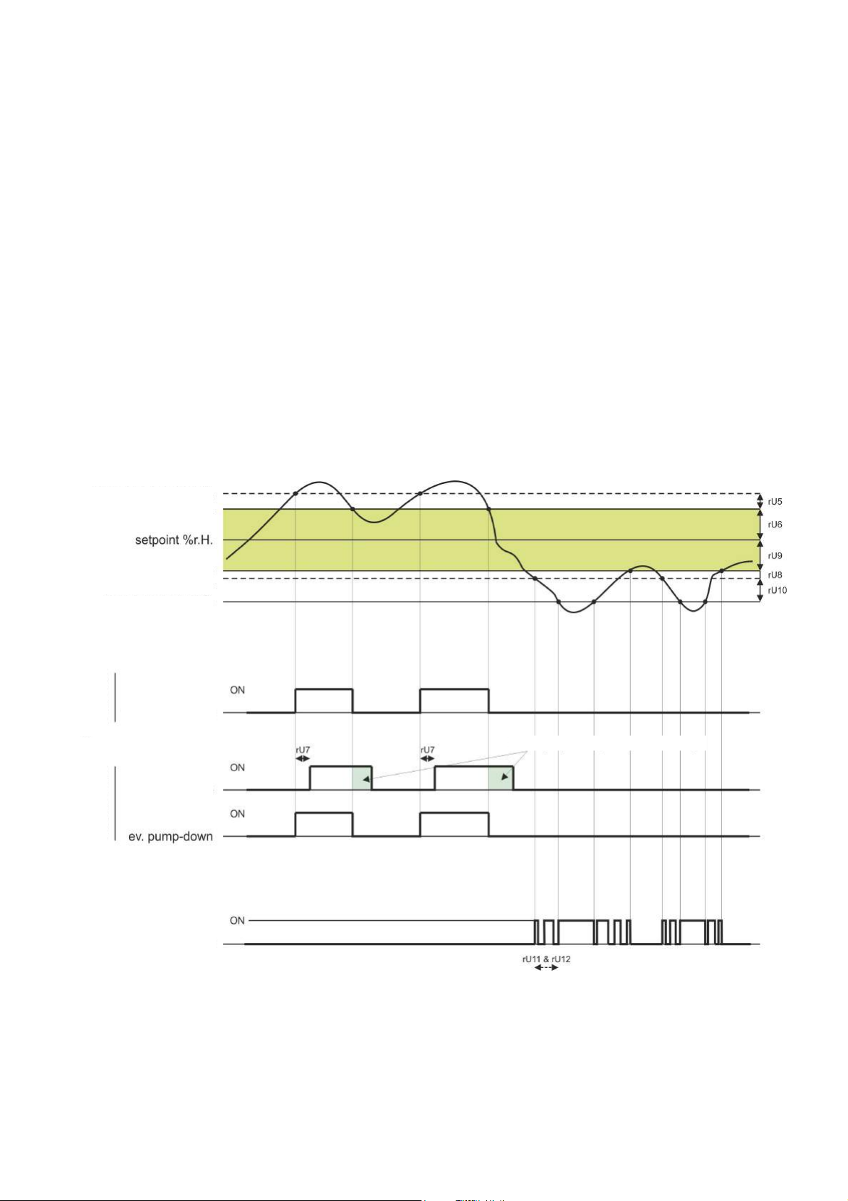
Dehumid. neutral
Dehumidify.
Dehumid. With
plant
compressor
Relay humidification
9.2.2 Generating heat
Generation of the heat refers to a heating element.
During a heating request, the heating element outputs will be activated, with possibility of management of a switch-on
and switch-off duty cycle, defined by parameters rH6 and rH7 in a way to limit the heating power if very powerful resistors
are used, in order to prevent overheating in the cabinet.
The evaporator fan will go continuously or in parallel to the resistors output, at the speed established for the phase in
progress.
9.3 Regulation of humidity
The regulation of the humidity in the cabinet for all phases where it is envisioned and with humidity transducer enabled, is
neutral area.
Meaning with a work set-point and a neutral area within which activations of loads set-up for humidification or
dehumidification do not take place.
When the humidity goes above the neutral area value of the dehumidification differential value, the utilities set-up for
dehumidification will be activated until the humidity returns within the neutral area value.
In the same way, when the humidity goes below the neutral area value of the humidification differential value, the utilities
set-up for humidification will be activated proportionally until the humidity returns within the neutral area value. (For
management without humidity transducer, see chapter 0).
Dehumid. differential
Humid. differential
Humid. neutral area
Humid. prop. band
Extraction fan
with fan
refrigeration
Pump-down duration (see dedicated chapter
Page 30 of 62
Page 31

EVCO S.p.A. EVFTFT618 | Installer manual ver. 2.2 | Code 144FTFT618E224
9.3.1 Humidification management
Generation of humidity refers to two different utilities, a humidity generator output and a humidifier output.
The humidity generator output is activated during the phases in which management of humidification is envisioned; it is
used for machines with external boiler, in order to generate the steam to be introduced successively into the cabinet
whenever requested by the regulator.
The humidifier output activates when the humidity value inside the cabinet drops below the neutral area value given by
the parameter rU9 of the humidification differential value given by the parameter rU8. The percentage activation of the
humidifier output will be proportional to the value of the humidity with respect to the humidification proportional band
defined by the parameter rU10. The humidification activation/deactivation cycle time is given by parameter ru11 and
regulated on the basis of times defined by parameter rU12.
9.3.2 Dehumidification management
Dehumidification can be managed in two different ways, via an extraction/dehumidifier fan (u3=1) or via the activation of
the cooling plant (u3=1).
In the case of management via extractor fan/dehumidifier, the output will activate when the humidity has exceeded the
dehumidification neutral area, given by parameter rU6 of the value of the differential value given by the parameter rU5
and deactivates when the humidity has returned within the dehumidification neutral area value.
The compressor will behave in the same way whenever the management of the pump-down electrovalve is enabled
(parameter u1 =1).
If pump-down electrovalve management is enabled (parameter u1=0), there will first be a dehumidification attempt via
activation of the electrovalve for a period of time equal to parameter rU7, to try and make use of the high pressure
generated during pump-down in compressor switch-off, on the expiry of which, the compressor output will be activated, if
dehumidification is still requested.
Once the humidity returns within the dehumidification neutral area value, the pump-down electrovalve will be deactivated.
After which, the compressor will deactivate via the pump-down algorithm.
10 Loads management
10.1 Management of the compressor
Compressor activation is subject to the delay time between the two switch-ons (parameter C1), the delay between switch-
off and successive activation (parameter C2), the activation delay from board power on (parameter C0) and the minimum
switch-on time (parameter C3).
The compressor can also be active during hot gas defrosting (parameter d1 = 1). In this case, for the defrosting to start,
the compressor must be active for at least the time established with parameter d15.
The compressor can also be used for dehumidification; for more details see paragraph 0.
Compressor switch-off is managed differently when management of the pump-down electrovalve management is
envisioned. For greater details see the staff 0.
10.2 Pump-down management
If output K8 is configured as pump-down electrovalve (parameter u1= 0), the controller will manage the interaction
between compressor output and electrovalve output as follows:
With timed pump-down (parameter u1 = 0 and i6 = 0 or 1):
On activation of the compressor in parallel, the pump-down electrovalve will also be activated.
Compressor deactivation will be advanced by the deactivation of the pump-down electrovalve; after time u2 the
compressor outlet will also be deactivated.
Page 31 of 62
Page 32

EVCO S.p.A. EVFTFT618 | Installer manual ver. 2.2 | Code 144FTFT618E224
With pump-down managed from LP digital input (parameter u1 = 0 and i6 = 2):
On activation of the compressor in parallel, the pump-down electrovalve will also be activated.
Compressor deactivation will be advanced by the deactivation of the pump-down electrovalve; the compressor will be
switched off successively via the intervention of the LP digital input.
Whenever the LP digital input does not intervene within maximum time U2, the compressor will be deactivated and the PD
alarm activated; an alarm turns off the high-pressure compressor regardless of the management of the pump-down.
If the pump-down is managed by the LP digital input, at every compressor output and electrovalve switch-on, a LP digital
input rearm time will be loaded (parameter i9). When the compressor is off, the status of the LP digital input will not be
considered.
10.3 Management of the evaporator fan
The evaporator fan is managed via the PWM analogue output and the phase cut module EVDFAN1 or via the digital output
K8 in On/Off mode if the parameter u1 = 1.
The evaporator fan can be configured for every phase of the cycle to operate continuously or in parallel to the adjustment
output, i.e. in parallel with the compressor, heating element, humidification and dehumidification. The definition of the
behaviour is given by the parameters from F0 to F4.
It will also be possible to establish a delay time for deactivation of the fan with respect to the adjustment output through
parameter F13 and a duty-cycle with a cycle time and an On time given by parameters F14 and F 15 during deactivation
of the main utility. If parameters F14 and F15 are at zero, there will be no activation.
In the event of evaporator fan management via PWM analogue output, it will also be possible to establish the speed of the
fan itself for every phase.
O fan switch-on the controller manages a speed (F21) and a peak time (F22) of the same. On conclusion of the ramp-up
phase, the fan will modulate according to the speed set for the phase in progress, compensated via parameters F23 and
F24, which respectively establish the minimum and maximum speed of the fan itself.
The fan is OFF during defrosting cycle. At the end of a defrosting cycle the evaporator fan will remain at a standstill for the
dripping time given by parameter d7 and for the successive evaporator fans standstill time given by parameter F12.
Evaporator fan calibration procedure managed via TDF module:
To adapt the TDF adjustment to all types of single-phase 230 Vac motors, it is recommended to perform manually
calibrate the evaporator fan.
1. Set F23 at 0% and F24 at 100%
2. Carry out a manual cycle and varying the fan speed, check the minimum percentage below which the fan
switches off and the maximum percentage above which the fan goes to maximum.
3. Set these values respectively for F23 and F24.
10.4 Defrosting management
Defrosting is active during the automatic LOCK and STORAGE phases and during the MANUAL COOLING phase and can be
automatic (at time intervals) or manual. Manual defrosting can be activated from the PRE-SELECTION, MANUAL CYCLE
RUN OPTIONS and AUTOMATIC CYCLE RUN OPTIONS menu.
Depending on the value of parameter d1, the machine will perform electric or hot gas defrosting cycles.
Defrosting will end on reaching the defrosting end temperature given by the parameter d2, if the evaporator probe is
enabled (parameter P3=1) or for maximum duration given by parameter d3. If the evaporator probe is enabled but
broken, defrosting ends due to maximum duration.
At the end of defrosting, the controller will perform a dripping time (d7) during which, all adjustment outputs will be
switched off. After dripping time, the cooling plant will start to operate again but the activation of the evaporator fan will
be delayed further by the time given by the parameter F12.
In the event of hot gas defrosting, the compressor must be activated for at least time d15 for the compressor to start.
Page 32 of 62
Page 33

EVCO S.p.A. EVFTFT618 | Installer manual ver. 2.2 | Code 144FTFT618E224
10.5 Management of the heating elements
During a heating request, the heating elements output will be activated, making the management of a switch-on/off duty-
cycle also possible, defined by parameters rH6 and rH7.
10.5.1 Cabinet step heating management
The desired set-point can be reached in the recovery and proving phases gradually, defining the number of steps to reach
the set-point and the percentage increase of the set-point for every step fixed.
For the recovery phase, the number of steps is defined by parameter rr0, while the percentage increases of the set-point
are given by parameters from rr1 to rr10.
For the proving phase, the number of steps is defined by parameter rL0, while the percentage increases of the set-point
are given by parameters from rrL1 to rL10.
Attention, it is the user's task to check the coherence of the number of steps set and the correct number of set-point
increase percentages. Example, if rr0 is equal to 4, only the parameters from rr1 to rr4 must be set.
10.6 Management of the steam generator
The steam generator output is active during all phases in which cabinet humidification management is envisioned.
10.7 Humidification management
The humidity in the cabinet can be managed with or without the use of humidity transducer, depending on the value of the
parameter rU0.
10.7.1 Management of humidity without transducer (rU0 = 1)
In this case, the humidifier output will remain active for a variable duty-cycle according to the humidity set-point set for
the phase in progress.
The duration of the activations and deactivations of the output is given by parameters rU2 (humidification cycle time) and
the maximum humidification time to obtain 100% humidity inside the cabinet (rU3).
The activation times will therefore be a percentage of the parameter rU3, on the basis of the set-point set, which will
repeat every cycle time set with rU2.
10.7.2 Management of humidity with transducer (rU0 = 0)
The humidifier output activates when the humidity value inside the cabinet drops below the neutral area value (rU9) of the
humidification differential value (rU8). The activation percentage of the humidifier output will be proportional to the value
of the humidity with respect to the humidification proportional band value (rU10), on the basis of the humidification cycle
time (rU11) and a times base for said time (rU12).
Page 33 of 62
Page 34

EVCO S.p.A. EVFTFT618 | Installer manual ver. 2.2 | Code 144FTFT618E224
10.8 Dehumidification management
Dehumidification management is only active when the humidity management takes place via the use of the humidity
transducer (rU0 = 0).
The dehumidification can be managed in two different ways: via an extractor fan (parameter u3 = 0, utility associated to
output K4) or via the activation of the cooling plant (compressor and pump-down electrovalve if present).
10.8.1 Management via extractor fan/dehumidifier
In the case of management via extractor fan/dehumidifier, the output will activate when the humidity has exceeded the
dehumidification neutral area, (rU6) of the value of the differential value (rU5) and deactivates when the humidity has
returned within the dehumidification neutral area value.
10.8.2 Management via cooling plant activation
The compressor will behave in the same way whenever the management of the pump-down electrovalve is enabled.
If, instead, pump-down electrovalve management is enabled, there will first be a dehumidification attempt via activation
of the electrovalve (rU7, to try and make use of the high pressure generated during pump-down in compressor switch-off
mode), on the expiry of which, the compressor output will be activated.
Once the humidity returns within the dehumidification neutral area value, the pump-down electrovalve will be deactivated.
After which, the compressor will deactivate via the pump-down algorithm.
10.9 Management of the condenser fan
If parameter u3 has value 1, output K4 will assume condenser fan control function.
If the condenser probe is active (parameter P4 = 1), the condenser fan will activate when the condenser temperature is
over the value of parameter F16 of the differential value (F16 + 2.0 °C / 4 °F), independently from the status of the
compressor, while it will always be on with the compressor on.
The condenser fan will switch-off when the condenser temperature drops below the value of parameter F16.
With condenser probe disabled (parameter P4 = 0) the condenser fan will be activated in parallel to the compressor, while
deactivation will be delayed by the time established with parameter F17.
The condenser fan is always on during an overheated condenser alarm (label COH) or compressor blocked (label CSd)
alarm.
The fans are handled during the hot gas defrost.
10.10 Cabinet light management
Cabinet light switch-on is enabled/disabled by opening/closing the door.
Light on with door open, light off with door closed.
Page 34 of 62
Page 35
EVCO S.p.A. EVFTFT618 | Installer manual ver. 2.2 | Code 144FTFT618E224
11 Alarms
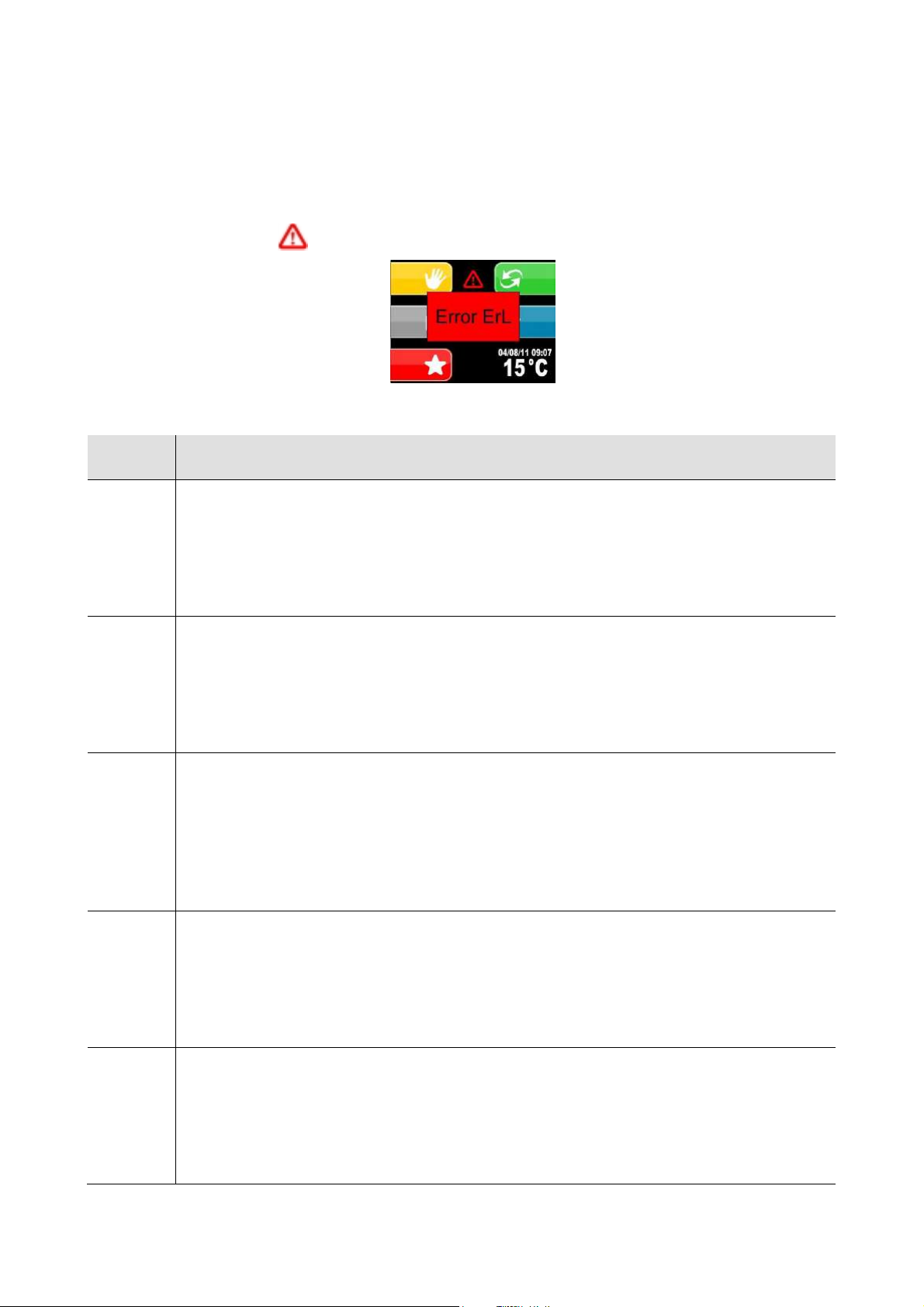
When an alarm occurs, a pop-up window opens a indicating the code of the alarm present. The buzzer sounds
intermittently until any key is pressed that silences the buzzer and makes the pop-up window disappear. The alarm
presence is indicated with the
The following table gives the alarms that may occur.
Code Part
Evaporator maximum temperature alarm
Solutions:
AH
id
HP
LP
CtH
- check the temperature of the evaporator.
- check the value of parameters A1 and A2.
Main consequences:
- signals only
Door open alarm
Solutions:
- check the door conditions
- check the value of parameters i0, i1 and i2.
Main consequences:
- the effect established with parameter i0
High pressure alarm.
Solutions:
- check the conditions of the high pressure input
- check the value of parameters i3, i4 and i5.
Main consequences:
- the effect established with parameter i3
- an alarm turns off the high-pressure compressor regardless of the management of the pump-down.
Low pressure alarm.
Solutions:
- check the conditions of the low pressure input
- check the value of parameter i6, i7, i8 and i9.
Main consequences:
- the compressor and the evaporator fan will be off (see parameter i6)
Compressor circuit breaker protection alarm.
Solutions:
- check the conditions of the compressor circuit breaker protection input
- check the value of the parameter i10 and i11.
Main consequences:
- the compressor will be switched off
icon.
Page 35 of 62
Page 36

EVCO S.p.A. EVFTFT618 | Installer manual ver. 2.2 | Code 144FTFT618E224
Power supply cut-off during execution of a cycle alarm
PF
Solutions:
- check the device-power supply connection
Condenser overheated alarm.
Solutions:
COH
- check the temperature of the condenser
- check the value of the parameter C6.
Main consequences:
- the condenser fan will be switched on
Compressor blocked alarm.
Solutions:
- check the temperature of the condenser
CSd
- check the value of parameters C7 and C8
- disconnect the device power supply and clean the condenser.
Main consequences:
- if the error occurs during an operating cycle, the cycle will be interrupted
Pump-down alarm
Solutions:
- check the maximum pump-down time established with parameter u2
PD
- the alarm will be rearmed on the successive activation of the compressor or by pressing the
buzzer silencing key
Main consequences:
- compressor switch-off
Cabinet probe error.
Solutions:
- check the value of the parameter P0
- check the integrity of the probe
Pr1
- check the device-probe connection
- check the temperature of the cabinet.
Main consequences:
- if the error occurs during the “stand-by” status, no operating cycles can be started
- if the error occurs during a cycle, the cycle will be interrupted
Evaporator probe error.
Solutions:
Pr2
- the same as the cabinet probe error (“Pr1” code) but relative to the evaporator probe.
Main consequences:
- if parameter P3 is set at 1, the defrosting period will last for the amount of time set with
parameter 3
Condenser probe error.
Solutions:
- the same as the cabinet probe error (“Pr1” code) but relative to the condenser probe.
Pr3
Main consequences:
- the condenser fan will operate parallel to the compressor
- the overheated condenser alarm (“COH” code) will never be activated
- the compressor blocked alarm (“CSd” code) will never be activated
Page 36 of 62
Page 37

EVCO S.p.A. EVFTFT618 | Installer manual ver. 2.2 | Code 144FTFT618E224
Humidity transducer error.
Solutions:
- check the integrity of the transducer
- check the device-transducer connection
- check the humidity relative to the cabinet.
Pr4
Main consequences if parameter rU0 is set at 0:
- if the error occurs during “stand-by”, cycles that envision humidity management cannot be
launched
- if the error occurs during the execution of a cycle that envisions humidity control, the cycle will
be interrupted.
Clock error.
Solutions:
rtc
- set the real date and time again.
Main consequences:
- the device will not be able to start automatic cycles
- any automatic cycles in progress will be blocked.
User interface-control module compatibility.
Solutions:
ErC
- check that the user interface and the control module are compatible.
Main consequences:
- interruption of cycle in progress.
User interface-control module communication error.
Solutions:
ErL
- check user interface-control module control module.
Main consequences:
- interruption of cycle in progress
Page 37 of 62
Page 38
EVCO S.p.A. EVFTFT618 | Installer manual ver. 2.2 | Code 144FTFT618E224
The connection of a USB pen in the USB
performed
Press SET to pass from one field to
The following screen will appear once
The following screen will appear once
the download/upload once finished
Remove the USB pen
Machine reset will be requeste
d
cycles/procedures. A red USB icon will appear on
USB icon will turn green to indicate that the pen
12 Management of the Host USB port on the board
The EVFTFT618 model mounts a USB port on the board able to perform the following functions:
- Allows the download of the data relative to the cycles performed onto USB (historic)
- Allows to download the programs saved in the controller onto USB pen
- Allows to download the parameters saved in the controller onto USB pen
- Allows to upload the programs saved in the USB pen into the controller
- Allows to upload the parameters saved in the USB pen into the controller
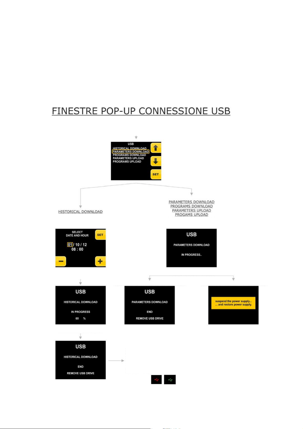
On connection of a pen to the USB port on the machine, with board in stand-by, a window will appear that will allow to
access the menu described in the following flow-chart.
input cause the USB menu to appear,
from where it will be possible to select
and display the operation to be
By selecting the HISTORICAL
DOWNLOAD menu
another and press START to begin the
download
By selecting one of these options the
execution screen will be shown
the download/upload once finished
In the case of download the following screen is obtained
Just for the HISTORICAL DOWNLOAD operation
which can have very long duration, it is possible
to press ESC during the download and go back
to the pre-selection page to start new
the display for the time the download is in
progress, while at the end of the download, the
can be removed
In the case of upload the following screen is obtained
On removal of the USB pen all
windows relative to USB
management will disappear
automatically
Page 38 of 62
Page 39
EVCO S.p.A. EVFTFT618 | Installer manual ver. 2.2 | Code 144FTFT618E224
13 Parameters
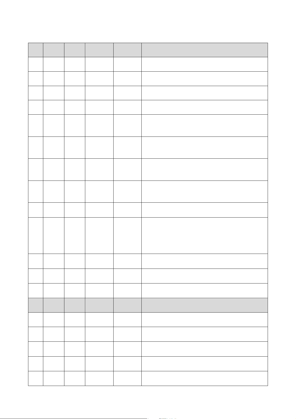
Par. Min. Max. Unit Default Analogue inputs
CA1 -25 25 °C 0 offset cell probe
CA2 -25 25 °C 0 offset evaporator probe
CA3 -25 25 °C 0 offset condenser probe
CA4 -25 25 %r.H. 0 humidity probe offset
probe type
P0 0 1 - - - - 1
P2 0 1 - - - - 0
P3 0 1 - - - - 1
P4 0 1 - - - - 0
P5 0 60 Min 15
P6 0 2 - - - - 1
P7 0 P8 %r.H. 0
P8 P7 100 %r.H. 100
P9 0 250 ds 5
0 = PTC
1 = NTC
temperature unit of measurement
0 = °C
1 = °F
enabling the evaporator probe
0 = disabled
1 = enabled
enabling the condenser probe
0 = disabled
1 = enabled
duration of a power supply cut-off during a higher cycle at
which a cycle is interrupted (see also P6)
behaviour of the instrument on power supply restore
0 = the cycle will be interrupted
1 = the cycle will be re-started
2 = the cycle will be restarted if the duration of interruption
has been less than parameter P5
humidity transducer low calibration limit (corresponding to
4mA)
humidity transducer high calibration limit (corresponding to
a 20mA)
delay displaying temperature variation detected by the
probes
Par. Min. Max. Unit Default Cooling regulator
rC0 1 15 °C 2 differential of the parameters rC3, rC4, rC5
rC1 -99 rC2 °C -20
rC2 rC2 99 °C 20
rC3 0 10 °C 1
rC4 0 10 °C 1
minimum set-point that can be set for the lock, storage and
manual cooling phases
maximum set-point that can be set for the lock, storage
and manual cooling phases
cooling neutral area value for the block, storage and
manual cooling phases
cooling neutral area value for the recovery, proving and
manual heating phases
Page 39 of 62
Page 40
EVCO S.p.A. EVFTFT618 | Installer manual ver. 2.2 | Code 144FTFT618E224
rC5 0 10 °C 1 cooling neutral area value for the baking delay phase
rC6 -99 99 °C 2 pre-cooling set-point
Par. Min. Max. Unit Default Heating regulator
rH0 1 15 °C 2 rH3, rH4, rH5 parameters differential
rH1 -99 rH2 °C 0
rH2 rH2 99 °C 40
rH3 0 10 °C 1
rH4 0 10 °C 1
minimum set-point that can be set for the recovery,
proving, making delay and manual heating phases
maximum set-point that can be set for the recovery,
proving, making delay and manual heating phases
heating neutral area value for the block, storage and
manual cooling phases
heating neutral area value for the recovery, proving and
manual heating phases
rH5 0 10 °C 1 heating neutral area value for the baking delay phase
rH6 1 600 sec 60
cycle time for switch-on of the heating elements in the
event of a heating request (see also rh7)
rH7 1 600 sec 45 heating elements switch-on time within the cycle time rH6
rr0 1 10 - - - - 4 number of regulation steps in the recovery phase
rr1 1 rr2 % 25
rr2 rr1 rr3 % 50
rr3 rr2 rr4 % 75
rr4 rr3 100 % 100
rr5 rr4 rr6 % - - - -
rr6 rr5 rr7 % - - - -
rr7 rr6 rr8 % - - - -
rr8 rr7 rr9 % - - - -
rr9 rr8 rr10 % - - - -
rr10 rr9 100 % - - - -
increase percentage 1st recovery step (with respect to
100% total)
increase percentage 2nd recovery step (with respect to
100% total)
increase percentage 3rd recovery step (with respect to
100% total)
increase percentage 4th recovery step (with respect to
100%)
increase percentage 5th recovery step (with respect to
100%)
increase percentage 6th recovery step (with respect to
100%)
increase percentage 7th recovery step (with respect to
100%)
increase percentage 8th recovery step (with respect to
100%)
increase percentage 9th recovery step (with respect to
100%)
increase percentage 10th recovery step (with respect to
100%)
rL0 1 10 - - - - 4 number of resistor regulation steps in the proving phase
rL1 1 rL2 % 25
increase percentage 1st proving step (with respect to
100%)
Page 40 of 62
Page 41
EVCO S.p.A. EVFTFT618 | Installer manual ver. 2.2 | Code 144FTFT618E224
rL2 rL1 rL3 % 50
rL3 rL2 rL4 % 75
rL4 rL3 100 % 100
rL5 rL4 rL6 % - - - -
rL6 rL5 rL7 % - - - -
rL7 rL6 rL8 % - - - -
rL8 rL7 rL9 % - - - -
rL9 rL8 rL10 % - - - -
rL10 rL9 100 % - - - -
increase percentage 2nd proving step (with respect to
100%)
increase percentage 3rd proving step (with respect to
100%)
increase percentage 4th proving step (with respect to
100%)
increase percentage 5th proving step (with respect to
100%)
increase percentage 6th proving step (with respect to
100%)
increase percentage 7th proving step (with respect to
100%)
increase percentage 8th proving step (with respect to
100%)
increase percentage 9th proving step (with respect to
100%)
increase percentage 1oth proving step (with respect to
100%)
Par. Min. Max. Unit Default Humidity regulator
humidity management mode:
rU0 0 1 - - - - 0
0 = with humidity probe
1 = at time cycles on the basis of the percentage set
rU1 -99 99 °C 0
rU2 1 600 sec 60
Minimum temperature in the cabinet below which the
humidification/dehumidification control is prevented
cycle time for switch-on of the humidifier (only for rU0 = 1,
see also uU3)
humidifier switch-on time within the cycle time uU2 to
rU3 1 600 sec 30
generate 100% humidity in the cabinet (only for rU0 = 1,
see also rU2)
rU4 0 1 - - - - 0
enabling of humidification/dehumidification control during
the block, storage and manual cooling phases
rU5 1 100 %r.H. 5 dehumidification differential
rU6 0 100 %r.H. 2 value of dehumidification neutral area
rU7 0 255 sec 10
dehumidification attempt duration with pump-down
electrovalve
rU8 1 100 %r.H. 5 humidification differential
rU9 0 100 %r.H. 2 value of humidification neutral area
rU1
0
rU1
1
rU1
2
0 50 %r.H. 10 value of humidification proportional band
0 255 s 30 cycle time for humidification proportional regulation
0 1 - - - - 0
base times for humidification proportional adjustment cycle
time:
Page 41 of 62
Page 42
EVCO S.p.A. EVFTFT618 | Installer manual ver. 2.2 | Code 144FTFT618E224
0 = seconds
1 = minutes
Par. Min. Max. Unit Default Compressor protection
C0 0 240 min 0 compressor switch-on delay from instrument switch-on
C1 0 240 min 2 minimum time between two compressor switch-ons (3)
C2 0 240 min 0 compressor switch off minimum duration
C3 0 240 s 0 minimum duration of compressor switch on time
C4 0 240 min 0
C6 0 199 °C 70
C7 0 199 °C 80
compressor forced switch-on duration and start of recovery,
proving and baking delay phases
condenser temperature above which the blocked
overheated condenser alarm is activated (“COH” code)
condenser temperature above which the blocked
compressor alarm is activated (“CSd” code)
C8 0 15 min 1 blocked compressor alarm delay (“CSd”code)
Par. Min. Max. Unit Default Defrosting
d0 0 99 h 6
defrosting interval
0 = defrosting will never be activated at intervals
type of defrosting
0 = electrical (the compressor will be switched off during
defrosting, the defrosting output will be activated
d1 0 1 - - - - 0
and the evaporator fan will be switched off)
1 = hot gas (the compressor will be switched on during
defrosting, the defrosting output will be activated
and the evaporator fan will be switched off)
d2 -99 99 °C 8
defrosting end temperature (evaporator temperature); see
also parameter d3
if parameter P3 is set at 0, duration of defrosting
d3 0 99 min 30
if parameter P3 is set at 1, maximum duration of
defrosting; see also parameter d2
0 = defrosting will never be activated
defrosting delay from start-up of storing/manual
d5 0 99 min 30
refrigeration
0 = defrosting will be started on expiry of the time
established with parameter d0
dripping duration (the compressor and the evaporator fan
d7 0 15 min 2
remain off during dripping and the defrosting output will be
deactivated)
minimum duration of compressor switch-on on activation of
d15 0 99 min 0
defrosting so these can be activated (only if parameter d1
is set at 1)
Par. Min. Max. Unit Default Temperature alarms
Page 42 of 62
Page 43
EVCO S.p.A. EVFTFT618 | Installer manual ver. 2.2 | Code 144FTFT618E224
evaporator temperature above which evaporator high
A1 0 99 °C 70
temperature alarm is activated (code “AH”); see also
parameter A2
A2 0 1 - - - - 1
enabling of evaporator high temperature alarm (“AH” code)
1 = yes
Par. Min. Max. Unit Default Evaporator and condenser fan
evaporator fan activity during block phase
F0 0 1 - - - - 0
0 = operation in parallel with compressor
1 = continuous operation
evaporator fan activity during storage. cooling, pre-cooling
F1 0 1 - - - - 0
phase
0 = operation in parallel with compressor
1 = continuous operation
evaporator fan activity during recovery phase
F2 0 1 - - - - 0
0 = operation in parallel with main utilities
1 = continuous operation
evaporator fan activity during proving, heating phase
F3 0 1 - - - - 0
0 = operation in parallel with main utilities
1 = continuous operation
evaporator fan activity during baking delay phase
F4 0 1 - - - - 0
0 = operation in parallel with main utilities
1 = continuous operation
F10 0 100 % 100 fan speed in pre-cooling phase
F11 0 100 % 100 fan speed in dehumidification phase
F12 0 15 m 2 fan stop after dripping phase
F13 0 250 s 0
F14 1 600 sec 0
delayed switch-off of the evaporator fan from main utilities
off
evaporator fan cycle time, if set at 0, the cyclical switch-on
of the fan will be deactivated.
F15 1 600 sec 0 evaporator fan switch-on time within the cycle time F14
F16 0 99 °C 20
F17 0 240 s 5
F18 0 240 s 15
temperature of the condenser above which the condenser
fan is on also with compressor off
condenser fan switch off delay on compressor switch off
(valid only with condenser probe disabled)
evaporator fan switch-on delay from door closure, i.e. from
the deactivation of the door micro switch input
F19 0 100 % 20 minimum evaporator fan speed settable
F20
0 100 % 100 maximum evaporator fan speed settable
F21 0 100 % 75 evaporator fan top speed
F22 1 10 s 5 top speed at evaporator fan switch-on
Page 43 of 62
Page 44
EVCO S.p.A. EVFTFT618 | Installer manual ver. 2.2 | Code 144FTFT618E224
and the heater
F23 0 100 % 35 evaporator fan min speed calibration value
F24 0 100 % 65 evaporator fan max speed calibration value
Par. Min. Max. Unit Default Digital inputs
effect caused by opening the door, i.e. by activation of the
door micro switch
0 = no effect
i0 0 2 - - - - 2
1 = the compressor, the evaporator fan
will be switched off and the cabinet will be switched
on
2 = the evaporator fan and the heater will be switched
off and the cabinet light will be switched on
type of door micro switch input contact
i1 0 1 - - - - 1
0 = normally open (input active with closed contact)
1 = normally closed (input active with open contact)
i2 -1 120 min 5
door open alarm signalling delay (“id” code)
-1 = the alarm will not be signalled
effect caused by the activation of the high pressure input
0 = no effect
i3 0 1 - - - - 1
1 = the compressor and the evaporator fan will be
switched off and the condenser fan will be switched
on
type of high pressure input 1
i4 0 1 - - - - 0
0 = normally open (input active with closed contact)
1 = normally closed (input active with open contact)
i5 -1 240 s 5
high pressure alarm signalling delay (“HP” code)
-1 = the alarm will not be signalled
effect caused by the activation of the low pressure input
0 = no effect
t1 = alarm the compressor and the evaporator fan will be
off
2 = pump-down management and alarm. In the
i6 0 2 - - - - 2
compressor switch-off phase, the intervention of the
digital input will switch the compressor output off to
end the pump-down phase . During the cooling plant
activation phases, the intervention of the digital
input will switch the compressor and the evaporator
fan off
type of low pressure input 1
i7 0 1 - - - - 0
0 = normally open (input active with closed contact)
1 = normally closed (input active with open contact)
i8 -1 240 s 10
i9 0 240 s 40
i10 0 1 - - - - 1
low pressure alarm signalling delay (“LP” code)
-1 = the alarm will not be signalled
low pressure switch rearm time on compressor switch on
(only if i6 =2)
type of circuit breaker protection input contact
0 = normally open (input active with closed contact)
Page 44 of 62
Page 45
EVCO S.p.A. EVFTFT618 | Installer manual ver. 2.2 | Code 144FTFT618E224
1 = normally closed (input active with open contact)
input circuit breaker protection alarm signal delay
i11 -1 240 s 5
(“CtH”code)
-1 = the alarm will not be signalled
Par. Min. Max. Unit Default Digital outputs
utility managed by the output K8
0 = pump down valve (in this case, parameter u2 will
u1 0 1 - - - - 0
have meaning)
1 = evaporator fan (in this case, the output will respond
to the status of the PWM output dedicated to the
evaporator fan in ON/OFF mode)
if i6 = 0 or 1:
compressor deactivation delay from pump-down valve
switch-off (pump-down in switch-off only for u1 = 0)
If i6 = 2:
u2 0 240 s 90
Pump-down maximum duration in compressor switch-off
mode without activation if the low pressure input such to
cause the compressor to switch-off and signal the pump-
down alarm.
0 = the alarm is not signalled
utility managed by the output K4
0 = dehumidifier/extractor fan (in this case, parameters
rU5 and rU6 will have meaning)
u3 0 1 - - - - 0
1 = condenser fan (in this case, the F16 and F17
parameters will assume significance)
N.B. with u3 = 1 dehumidification will be automatically
managed via the activation of the cooling plant
Par. Min. Max. Unit Default
Serial communication (RS-48 serial port with
MODBUS communication protocol)
L1 1 240 min 5 internal data sampling time
LA 1 247 - - - - 247 device address
baud rate
0 = 2,400 baud
Lb 0 3 - - - - 2
1 = 4,800 baud
2 = 9,600 baud
3 = 19,200 baud
parity
LP 0 2 - - - - 2
0 = none (no parity)
1 = odd
2 = even
Par. Min. Max. Unit Default Other
keyboard lock
E8 0 2 - - - - 2
0 = disabled
1= manual
Page 45 of 62
Page 46

EVCO S.p.A. EVFTFT618 | Installer manual ver. 2.2 | Code 144FTFT618E224
2 = automatic after 1 minute of inactivity during a cycle
display of the EVCO splash screen on power supply restore
E9 0 1 - - - - 1
0 = black screen
1 = EVCO splash
orientation of the display
E10 0 1 - - - - 1
0 = device positioned high with respect to unit
1 = device positioned low with respect to unit
E11 0 120 s 10 buzzer duration during the pre-cooling phase and cycle end
E12 0 1 - - - - 0 reserved
Page 46 of 62
Page 47
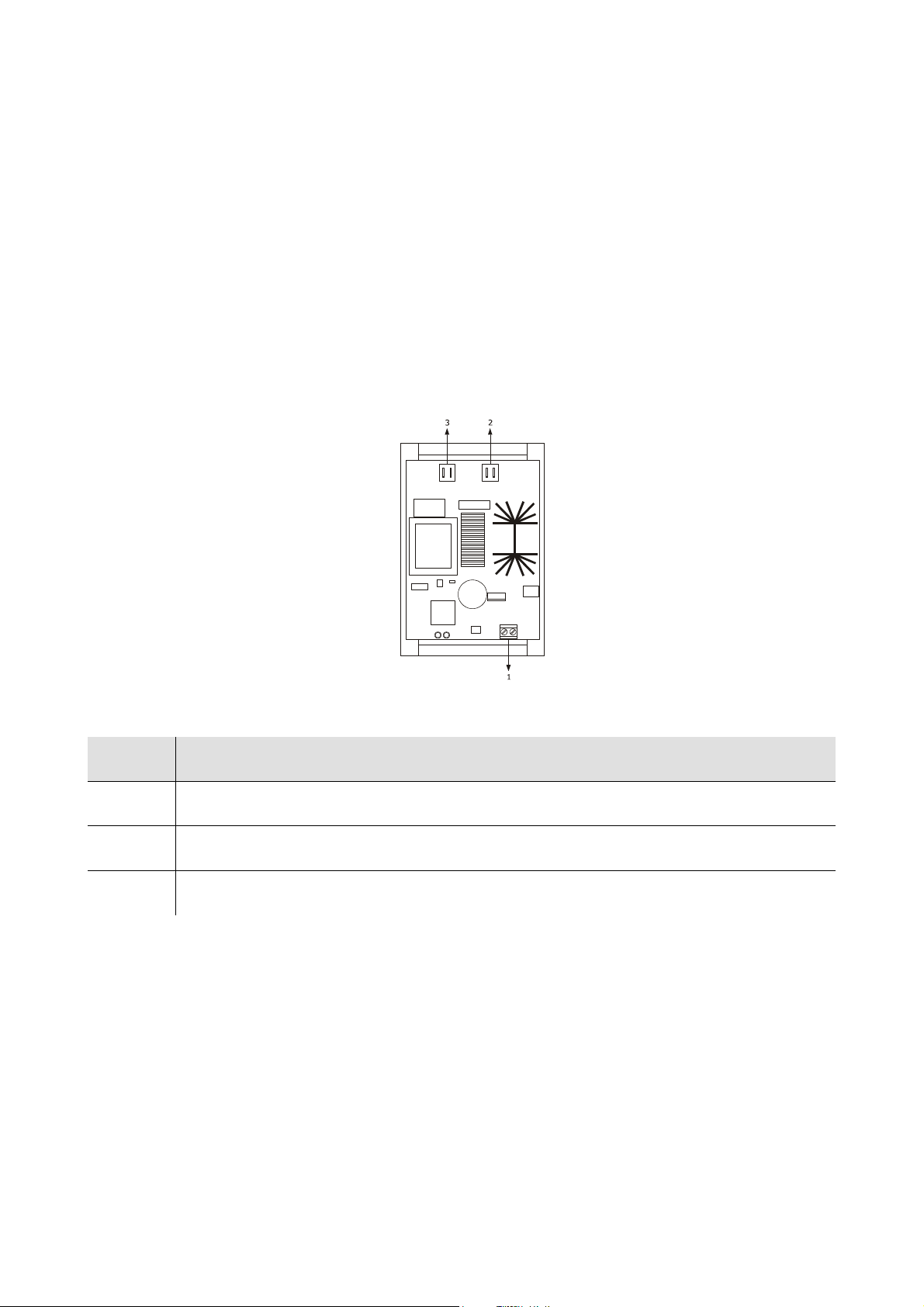
EVCO S.p.A. EVFTFT618 | Installer manual ver. 2.2 | Code 144FTFT618E224
14 Accessories
14.1 Phase cut speed regulator for single phase fans
EVDFAN1
14.1.1 Introduction
EVDFAN1 is a phase cut speed regulator for single phase fans.
The regulator control signal is the PWM type, the same supplied by the controller analogue output.
The maximum current allowed on the fan is 5 A.
14.1.2 Description
The following drawing illustrates the aspect of the EVDFAN1.
The following table illustrates the meaning of EVDFAN1 parts.
Part Part
1 control signal input
2 power supply
3 phase cut output
Page 47 of 62
Page 48
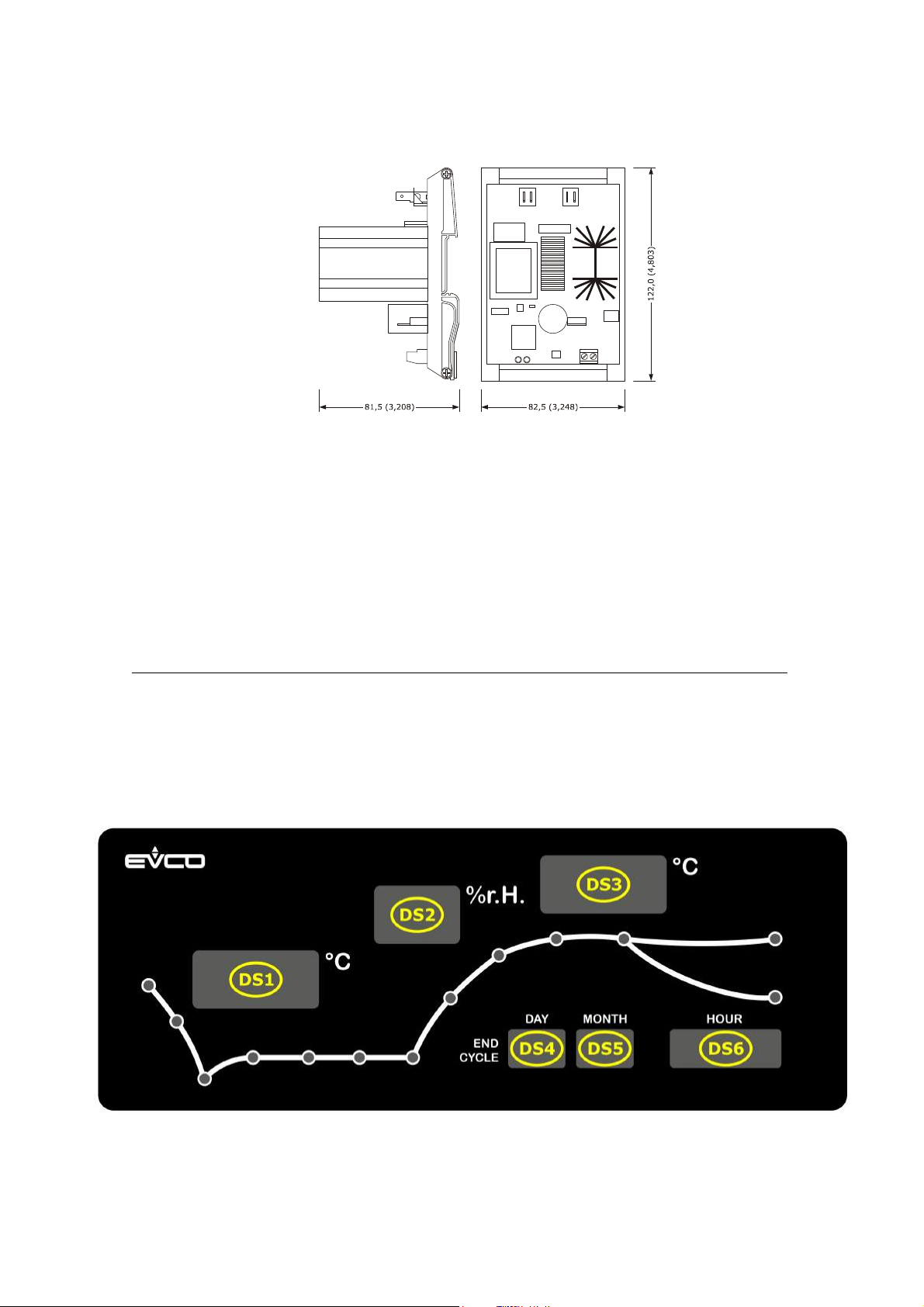
EVCO S.p.A. EVFTFT618 | Installer manual ver. 2.2 | Code 144FTFT618E224
14.1.3 Dimensions
The following drawing illustrates the EVDFAN1 dimensions; these are expressed in mm (in).
14.1.4 Connection to the device
Operate as follows:
2. Cut the device power supply off.
3. Cut the EVDFAN1 power supply off.
4. Connect the device PWM analogue output to the EVDFAN1 control signal input.
5. Connect the evaporator fan to the EVDFAN1 phase cut output.
6. Connect the device power supply.
7. Connect the EVDFAN1 power supply.
8. It is recommended to perform the evaporator fan manual calibration procedure described in paragraph 10.3.
In order to use EVDFAN1, the phase that powers the controller must be the same that powers EVDFAN1.
For further information, consult the documentation relative to EVDFAN1.
14.2 Synoptic Panel EVC25T00X7XXX04
This board reproduces the status of EVFTFT618. It is an optional board. Lack of the same does not generate any alarm
signal.
On system power on, the synoptic performs a lamp test with duration of 10 seconds.
Page 48 of 62
Page 49

EVCO S.p.A. EVFTFT618 | Installer manual ver. 2.2 | Code 144FTFT618E224
At the end, it shows the OFF label on display DS1 if EVFTFT618 is in standby, or it shows the cabinet temperature and the
current time on display DS6.
During setting of the set-point of a manual cooling cycle, the temperature set-point is displayed on DS1 and the humidity
set-point on display DS2 (if humidity control is envisioned, otherwise the display remains off). The other displays are off.
During the execution of the manual cooling cycle it shows the cabinet temperature on display DS1, the relative humidity
value or the humidity set-point on DS2 or the display remains off (depending on parameters rU0 and rU4), the current
time is on display DS6. The other displays are off.
During setting of the set-point of a manual heating cycle, the temperature set-point is displayed on DS1 and the humidity
set-point on display DS2 (depending on parameter rU0). The other displays are off.
During the execution of the manual heating cycle it shows the cabinet temperature on display DS3, the relative humidity
value or the humidity set-point on DS2 (depending on parameter rU0), the current time is on display DS6.
During setting of an automatic program, the following is displayed:
For the block phase, the cabinet temperature set-point is on display DS1, the humidity set-point on DS2 (if humidity
control is envisioned) and the duration is on display DS6
For the storage phase, the cabinet temperature set-point is on display DS1, the humidity set-point on DS2 (if humidity
control is envisioned)
For the recovery and proving phase, the cabinet temperature set-point on the display DS3, the humidity set-point on DS2
and duration on DS6
For the baking delay phase, the cabinet temperature set-point is on display DS3, the humidity set-point on DS2.
During execution of an automatic program, the following is displayed:
For the block phase, the cabinet temperature on the display DS1, the humidity set-point or the relative humidity on DS2
(depending on parameters rU0 and rU4), the program end day on display DS4, the program end month on DS5 and the
program end time on DS6;
For the storage phase, the cabinet temperature on the display DS1, the humidity set-point or the relative humidity on DS2
(depending on parameters rU0 and rU4), the program end day on display DS4, the program end month on DS5 and the
program end time on DS6;
For the recovery and proving phase, the cabinet temperature on the display DS3, the humidity set-point or the relative
humidity on DS2 (depending on parameter rU0), the program end day on display DS4, the program end month on DS5
and the program end time on DS6;
For the baking delay phase, the End label on DS1, the cabinet temperature on display DS3, the humidity set-point or the
relative humidity on DS2 (depending on parameter rU0), the current time is on DS6.
If defrosting is activated (manual or automatic), the display DS1 shows the DEF label for the entire duration of defrosting.
If an alarm occurs, the display DS1 shows the ALL label until any key is pressed.
Page 49 of 62
Page 50
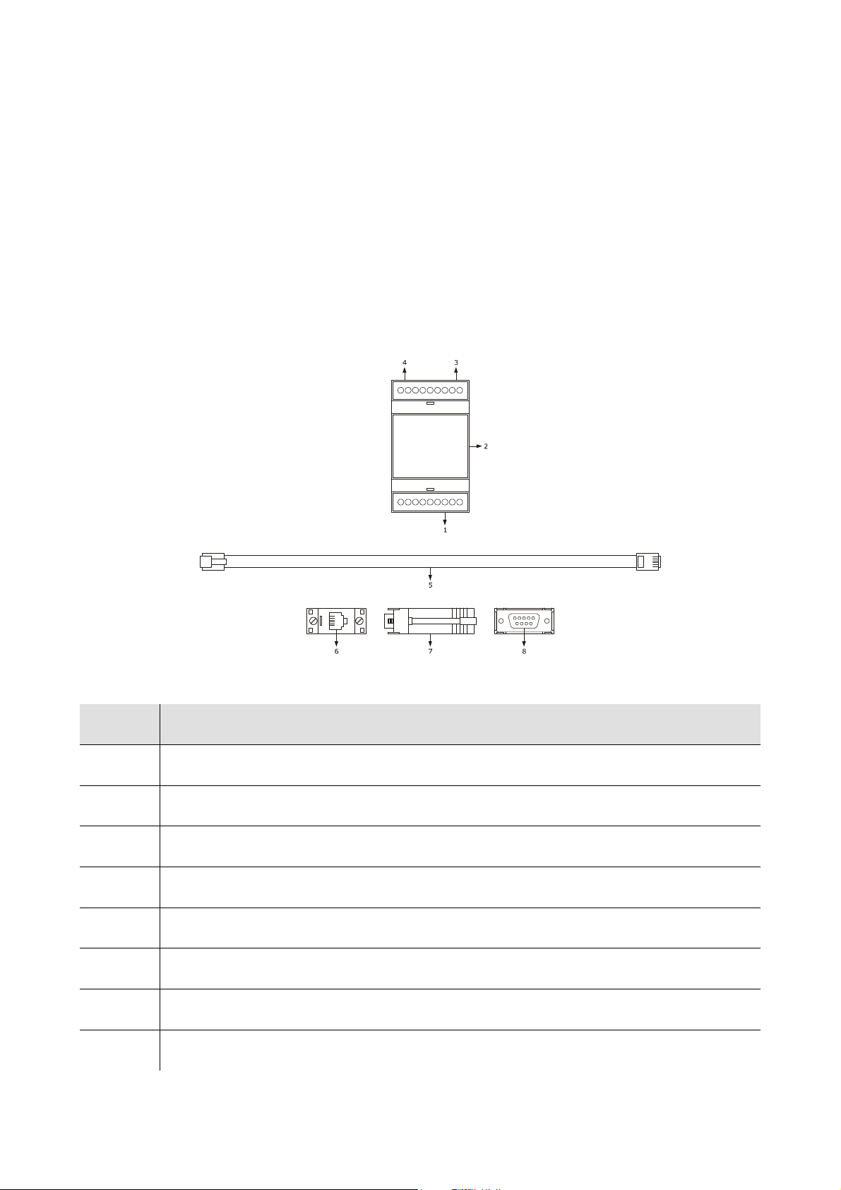
EVCO S.p.A. EVFTFT618 | Installer manual ver. 2.2 | Code 144FTFT618E224
14.3 Optoisolated RS-485/RS-232 serial interface
EVIF21RS7I
14.3.1 Introduction
EVIF21RS7I is an optoisolated RS-485/RS-232 serial interface.
The interface can be used to connect the controller to the Parameters Manager set-up software system.
The Personal Computer must have a free COM port; to connect the driver via a USB port, the adapter must also be used
from COM to USB 0810500011.
14.3.2 Description
The following drawing illustrates the aspect of the EVIF21RS7I.
The following table illustrates the meaning of the EVIF21RS7I parts.
Part Part
1 RS-485 type serial port
2 EVIF21RS7I
3 power supply
4 RS-232 type serial port
5 1256800042 telephone cable
6 RJ connector
7 1256800079 adapter
8 DB connector
Page 50 of 62
Page 51
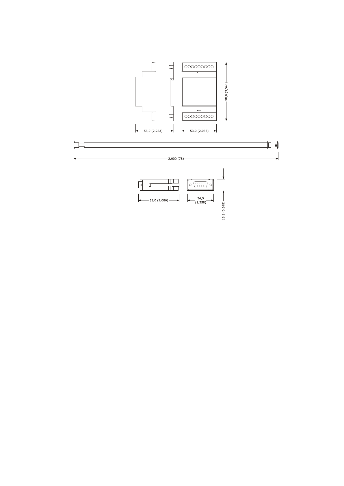
EVCO S.p.A. EVFTFT618 | Installer manual ver. 2.2 | Code 144FTFT618E224
14.3.3 Dimensions
The following drawing illustrates the EVIF21RS7I dimensions; these are expressed in mm (in).
14.3.4 Connection to the device
Operate as follows:
1. Cut the device power supply off.
2. Connect the device RD-485 serial port to the EVIF21RS7I RS-485 type serial port.
3. Insert one end of the telephone cable 1256800042 into the EVIF21RS7I RS-232 serial port.
4. Insert the other end of the telephone cable 1256800042 into the 1256800079 adapter RJ connector.
5. Connect the 1256800079 adapter DB connector to a Personal Computer COM, in which Parameters Manager is
installed.
6. Connect the device power supply.
Page 51 of 62
Page 52
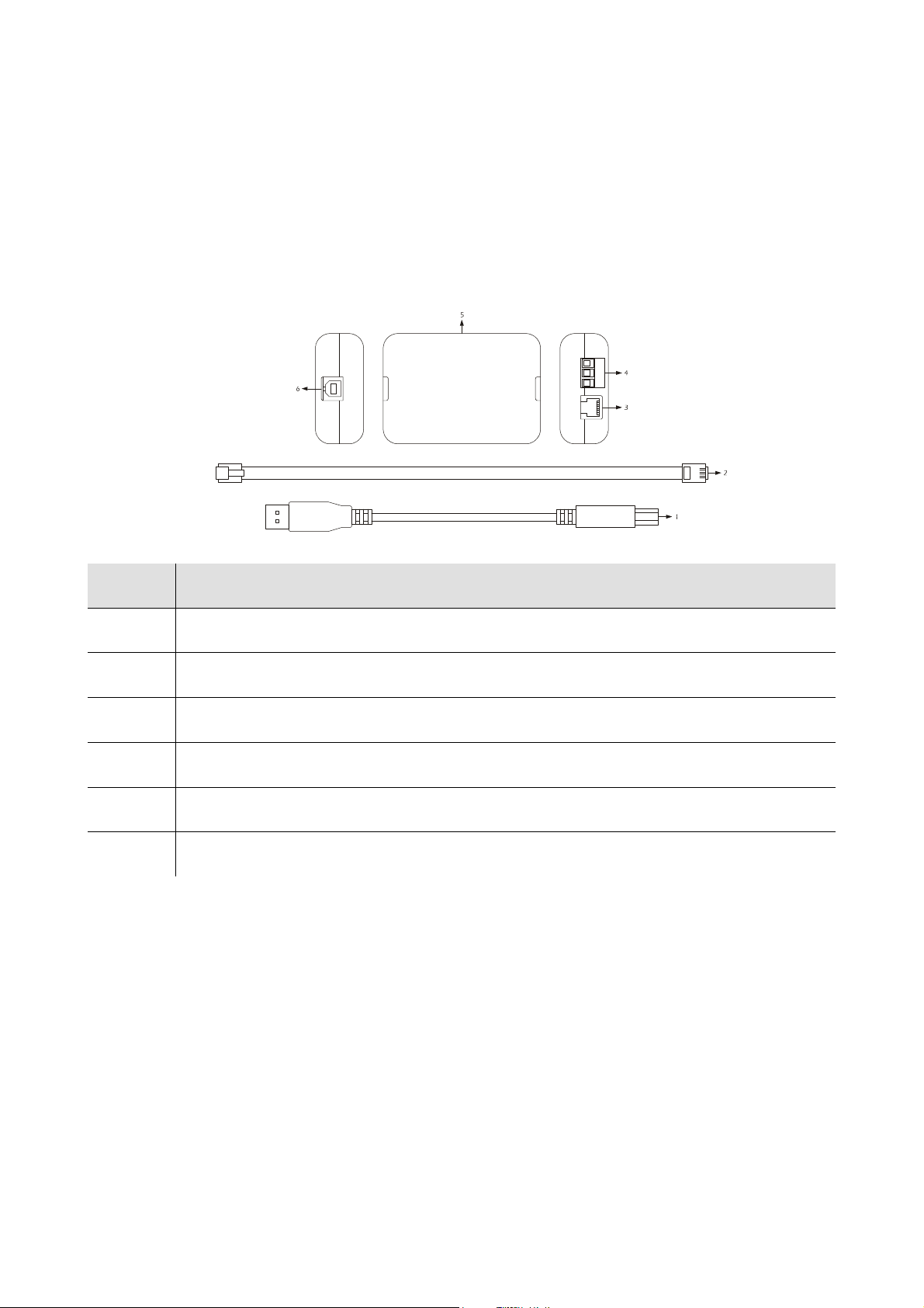
EVCO S.p.A. EVFTFT618 | Installer manual ver. 2.2 | Code 144FTFT618E224
14.4 Non-isolated RS-485/USB serial interface EVIF20SUXI
14.4.1 Introduction
EVIF20SUXI is a non-isolated RS-485/USB serial interface.
The interface can be used to connect the controller to the Parameters Manager set-up software system.
The Personal Computer must have a free USB port.
14.4.2 Description
The following drawing illustrates the aspect of the EVIF20SUXI.
The following table illustrates the meaning of the EVIF21RS7I parts.
Part Part
1 USB cable (length of 2 m)
2 RS-485 cable with length of 2.5 m
3 RS-485 port on telephone connector
4 RS-485 port on screw terminal
5 RS-485/USB non-isolated interface
6 USB port
Page 52 of 62
Page 53
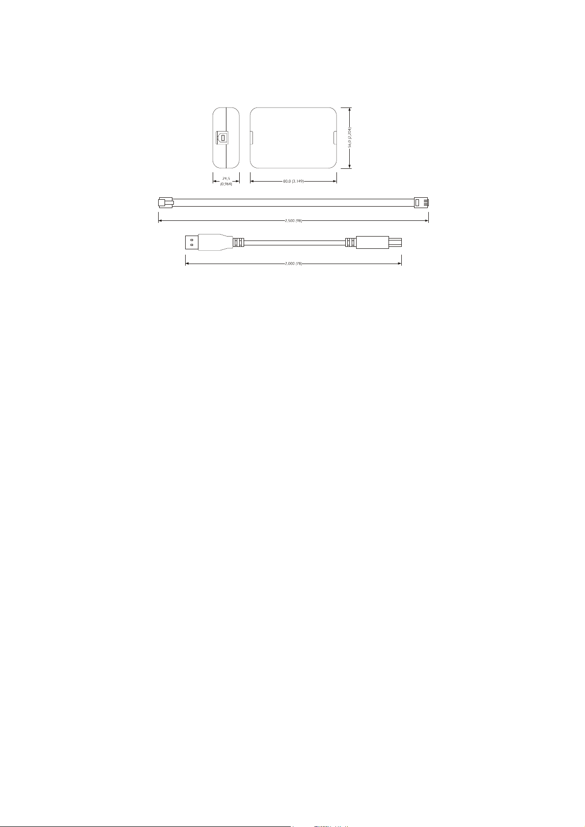
EVCO S.p.A. EVFTFT618 | Installer manual ver. 2.2 | Code 144FTFT618E224
14.4.3 Dimensions
The following drawing illustrates the EVIF20SUXI dimensions; these are expressed in mm (in).
14.4.4 Connection to the device
Operate as follows:
1. Cut the device power supply off.
2. Connect the device RD-485 serial port to the EVIF20SUXI RS-485 type serial port.
3. Insert one end of the USB cable into the EVIF20SUXI USB port.
4. Connect the other end of the USB cable to the USB connector of the Personal Computer.
Page 53 of 62
Page 54
EVCO S.p.A. EVFTFT618 | Installer manual ver. 2.2 | Code 144FTFT618E224
15 TECHNICAL DATA
15.1 Technical data
Purpose of the device: retarder proofer controller
user interface control module
Execution:
Dimensions:
board without cover behind a
Plexiglas sheet.
user interface control module
200.0 x 135.0 x 28.0 ±0.6 mm
(7.874 x 5.314 x 1.102
±0.023 in; L x H x D).
user interface control module
board without cover.
166.0 x 116.0 x 44.0 mm (6.535 x
4.566 x 1.732 in;
L x H x D).
Installation:
back panel via studs. on flat surface, with spacers.
Page 54 of 62
Page 55
EVCO S.p.A. EVFTFT618 | Installer manual ver. 2.2 | Code 144FTFT618E224
user interface control module
Protection rating:
IP65. IP00.
user interface control module
Connections:
removable screw terminal board
(control module and RS-485 serial
port).
The maximum length of the user
interface- control module connection is 10 m (32.808 ft).
Operating temperature: from 0 to 55 °C (from 32 to 131 °F).
Storage temperature: from -10 to 70 °C (from 14 to 158 °F).
terminal board with extractable
screws (user interface, power
supply, inputs, outputs).
Humidity for use: from 10% to 90% relative humidity without condensate.
Page 55 of 62
Page 56
EVCO S.p.A. EVFTFT618 | Installer manual ver. 2.2 | Code 144FTFT618E224
cut: 24 h with battery fully
Battery charging time: 2 min (the battery is charged by the device power
Pollution situation: normal.
user interface control module
Power:
supplied from the control module.
Overvoltage category: integrated control.
incorporated (with condenser).
Clock:
Battery autonomy in the event of a power-
charged.
115/230 VAC (±15%), 50 / 60 Hz
(±3 Hz), 10 VA max.
supply).
Signal buzzer and alarm: incorporated.
Page 56 of 62
Page 57
EVCO S.p.A. EVFTFT618 | Installer manual ver. 2.2 | Code 144FTFT618E224
cabinet probe, evaporator probe, condenser probe), can be set via
4 inputs (door micro switch, high pressure, low pressure and compressor
be set via configuration parameter due
free contact, 5
320 x 240 pixel
3 inputs (
configuration parameter for PTC/NTC probes
1 digital input (humidity sensor).
PTC type analogue inputs (990 Ω @ 25°C, 77°F)
Type of sensor: KTY 81-121.
Measurement field: from -50 to 150℃
(from -58 to 302°F).
Resolution: 1 °C (1 °F).
Analogue inputs:
Protection: none.
NTC type analogue inputs (10K Ω @ 25°C, 77°F)
Type of sensor: ß3435.
Measurement field: from -40 to 105℃
(from -40 to 220 ℃).
Resolution: 1 °C (1 °F).
Protection: none.
Digital inputs:
Displays:
4-20 mA analogue input
circuit breaker protection), which can
to normally open contact/normally closed contact (potential-
VDC, 2 mA)
Digital inputs
Power: none.
Protection: none.
(3.5 inch) colour TFT graphics display
Analogue outputs: 1 PWM output for management of the evaporator fan.
Page 57 of 62
Page 58

EVCO S.p.A. EVFTFT618 | Installer manual ver. 2.2 | Code 144FTFT618E224
for management of the cabinet light, humidifier,
down
Type of actions and complementary
48 serial port with
8 outputs (electromechanical relays):
N° 1:16 A res. @ 250 VAC or compressor management.
Digital outputs:
N° 1: 16 A res. @ 250 VAC for management of the heating elements.
N° 6: 8 A res. @ 250 VAC
dehumidifier/condenser fan, defrosting, steam generator and pump-
valve/evaporator fan.
features:
Communication port:
1C.
2 ports:
- 1 RS-
MODBUS communication protocol.
- 1 USB type serial port
Page 58 of 62
Page 59

EVCO S.p.A. EVFTFT618 | Installer manual ver. 2.2 | Code 144FTFT618E224
Notes
______________________________________________________________________________________________
______________________________________________________________________________________________
______________________________________________________________________________________________
______________________________________________________________________________________________
______________________________________________________________________________________________
______________________________________________________________________________________________
______________________________________________________________________________________________
______________________________________________________________________________________________
______________________________________________________________________________________________
______________________________________________________________________________________________
______________________________________________________________________________________________
______________________________________________________________________________________________
______________________________________________________________________________________________
______________________________________________________________________________________________
______________________________________________________________________________________________
______________________________________________________________________________________________
______________________________________________________________________________________________
______________________________________________________________________________________________
______________________________________________________________________________________________
______________________________________________________________________________________________
______________________________________________________________________________________________
______________________________________________________________________________________________
______________________________________________________________________________________________
______________________________________________________________________________________________
______________________________________________________________________________________________
______________________________________________________________________________________________
______________________________________________________________________________________________
______________________________________________________________________________________________
______________________________________________________________________________________________
______________________________________________________________________________________________
______________________________________________________________________________________________
______________________________________________________________________________________________
______________________________________________________________________________________________
______________________________________________________________________________________________
______________________________________________________________________________________________
Page 59 of 62
Page 60

EVCO S.p.A. EVFTFT618 | Installer manual ver. 2.2 | Code 144FTFT618E224
______________________________________________________________________________________________
______________________________________________________________________________________________
______________________________________________________________________________________________
______________________________________________________________________________________________
______________________________________________________________________________________________
______________________________________________________________________________________________
______________________________________________________________________________________________
______________________________________________________________________________________________
______________________________________________________________________________________________
______________________________________________________________________________________________
______________________________________________________________________________________________
______________________________________________________________________________________________
______________________________________________________________________________________________
______________________________________________________________________________________________
______________________________________________________________________________________________
______________________________________________________________________________________________
______________________________________________________________________________________________
______________________________________________________________________________________________
______________________________________________________________________________________________
______________________________________________________________________________________________
______________________________________________________________________________________________
______________________________________________________________________________________________
______________________________________________________________________________________________
______________________________________________________________________________________________
______________________________________________________________________________________________
______________________________________________________________________________________________
______________________________________________________________________________________________
______________________________________________________________________________________________
______________________________________________________________________________________________
______________________________________________________________________________________________
______________________________________________________________________________________________
______________________________________________________________________________________________
______________________________________________________________________________________________
______________________________________________________________________________________________
______________________________________________________________________________________________
______________________________________________________________________________________________
______________________________________________________________________________________________
Page 60 of 62
Page 61

EVCO S.p.A. EVFTFT618 | Installer manual ver. 2.2 | Code 144FTFT618E224
EVFTFT618
Installer manual ver. 2.2
EB - 02 / 14
Code 144FTFT618E224
This document is exclusive property of EVCO. Reproduction and disclosure are prohibited without express authorisation
from EVCO.
EVCO is not liable for any features, technical data and possible errors stated in this document or deriving from use of the
same.
EVCO cannot be considered liable for damage caused by failure to comply with warnings given in this document.
EVCO reserves the right to make any changes without forewarning, without jeopardising the basic safety and operating
features.
Page 61 of 62
Page 62

EVCO S.p.A. EVFTFT618 | Installer manual ver. 2.2 | Code 144FTFT618E224
EVCO S.p.A.
Via Feltre 81, 32036 Sedico Belluno ITALIA
Tel. 0437 / 8422
Fax 0437 / 83648
[email protected]
www.evco.it
Page 62 of 62
 Loading...