

EUTECH INSTRUMENTS ALPHA RES 1000 RESISTIVITY CONTROLLERTRANSMITTER, alpha-RES1000 Instruction Manual
Technolo
gyM
adeEa
sy...
Instruction Manual
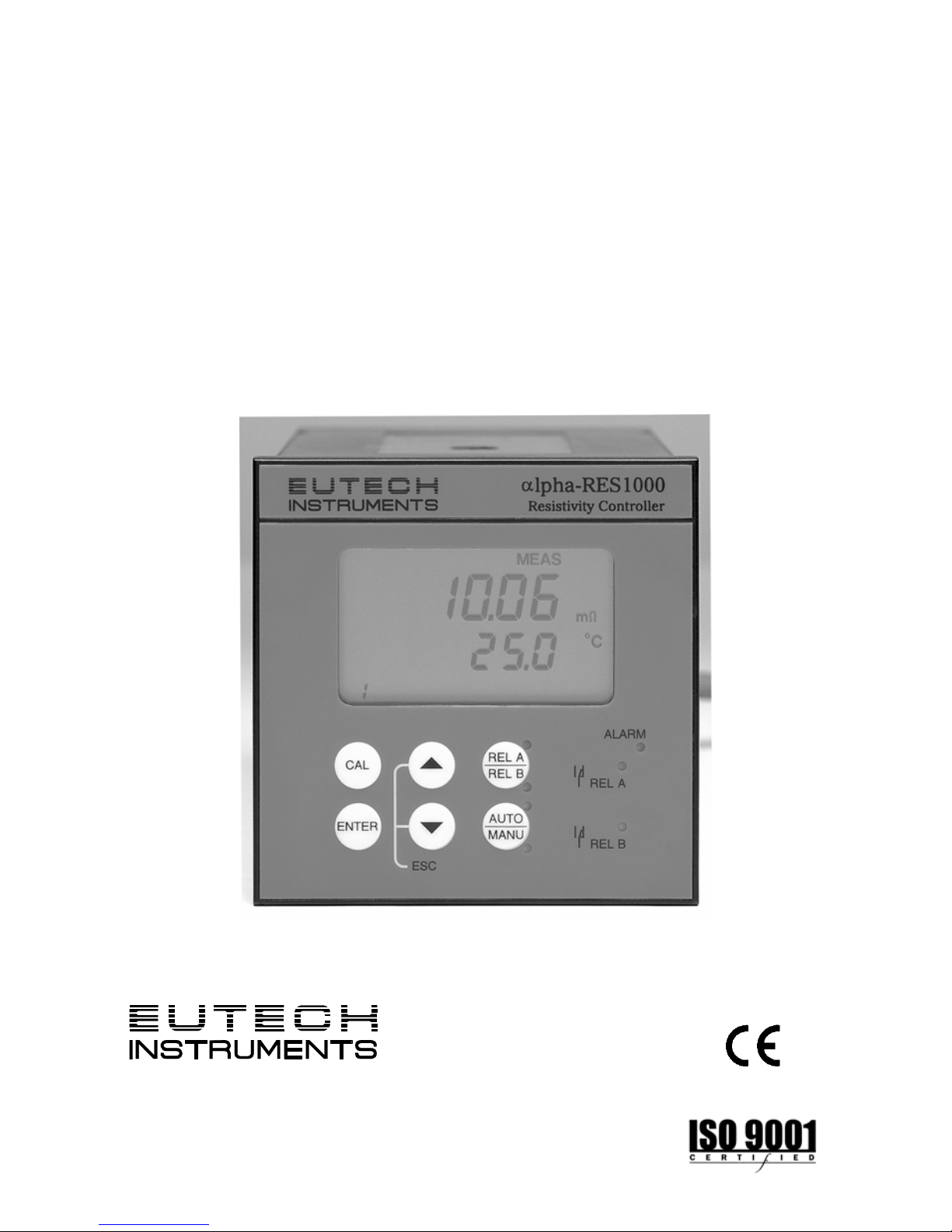
αlpha-RES1000
Resistivity Controller/Transmitter
68X216807 rev 3 12/04


Preface
This instruction manual serves to explain the use of the αlpha-RES1000 series Resistivity
controller/transmitter. The m anual functions in two ways: firstly as a step by step guide to help th e
user operate the instrument. Secondly, it serves as a handy reference guide. This instruction
manual is written to cover as many anticipated applications of the αlpha-RES1000 Resistivity
controller/transmitter. If you have doubts in the use of the instrument, please do not hesitate to
contact the nearest Eutech Instruments’ Authorised Distributor.
The information presented in this manua l is subject to change without notice as improvem ents are
made, and does not represent a commitment on part of Eutech Instruments Pte Ltd.
Eutech Instruments cannot acc ept any responsibility for damage or mal function of the unit due to
improper use of the instrument.
Copyright ©1999
Rev 3 12/04
All rights reserved.
EUTECH INSTRUMENTS PTE LTD
Blk 55 Ayer Rajah Crescent, #04-16/24, Singapore 139 949.
Tel: (65) 6778 6876; Fax: (65) 6773 0836
E-MAIL: MARKETING@EUTECHINST.COM
;
WEB SITE: HTTP://WWW.EUTECHINST.COM

Operating Instructions αlpha-RES1000
TABLE OF CONTENTS
1
INTRODUCTION.................................................................................................1
1.1 DESCRIPTION OF UNIT ....................................................................................1
1.2 APPLICATIONS................................................................................................ 1
2 ASSEMBLY AND INSTALLATION.....................................................................2
2.1 MEASUREMENT AND CONTROL SYSTEM............................................................2
2.2 UNIT DIMENSIONS ..........................................................................................2
3 ELECTRICAL CONNECTION.............................................................................3
3.1 CONNECTION DIAGRAM...................................................................................3
3.2 BACK PANEL..................................................................................................4
4 OVERVIEW.........................................................................................................5
4.1 KEYPAD AND DISPLAY.....................................................................................5
4.1.1 Keypad ..............................................................................................................5
4.1.2 Display............................................................................................................... 5
4.2 FUNCTION GROUPS ........................................................................................6
4.3 CONTROL CONCEPT .......................................................................................7
5 MEASUREMENT ................................................................................................8
5.1 DISPLAY IN MEASUREMENT MODE ....................................................................8
5.1.1 Check electrode performance ........................................................................... 8
5.1.2 Checking set points........................................................................................... 8
5.2 SECURITY CODES...........................................................................................8
5.2.1 How to enter and change parameters in Calibration mode ............................... 8
5.2.2 How to enter and change parameters in Advanced Setup mode...................... 9
6 CALIBRATION MODE......................................................................................10
6.1 RESISTIVITY CALIBRATION.............................................................................10
7 ADVANCED SET-UP MODE............................................................................11
7.1 TEMPERATURE COEFFICIENT SUB-FUNCTION...................................................11
7.1.1 Selecting Pure-water or Linear Temperature Coefficient ................................11
7.2 TEMPERATURE CALIBRATION (ATC MODE ONLY)..............................................12
7.2.1 Setting manual temperature compensation..................................................... 12
7.3 CONTROL RELAY A/CONTROL RELAY B (SP1/SP2) SUB-FUNCTION ..................13
7.3.1 Entering the Set point 1 (Set point 2) sub-function.......................................... 13
7.3.2 Selecting the set point values.......................................................................... 13
7.3.3 Choosing High or Low set points..................................................................... 13
7.3.4 Selecting a hysteresis (dead band) value (0.000 to 0.200 m
Ω
or 0.00 to 2.00
m
Ω
) 14
7.3.5 Setting an on-delay time lag............................................................................ 14
7.3.6 Setting an off-delay time lag............................................................................ 15
7.4 CONTROLLER (CNTR) SUB-FUNCTION .............................................................15
7.4.1 Entering the Controller sub-function................................................................ 15
7.4.2 Choosing the controller type (limit or proportional).......................................... 15
7.4.3 Choosing break/make contact relay type ........................................................ 16
7.4.4 Selecting proportional range value Xp............................................................. 16

Operating Instructions αlpha-RES1000
7.4.5 Maximum Pulse Length (tPL) or Maximum Frequency (FPF) ......................... 17
7.5 MEASUREMENT RANGE SUB-FUNCTION...........................................................17
7.5.1 Entering the Measuring Range sub-function ................................................... 17
7.5.2 Selecting Measuring Range sub-function........................................................ 17
7.5.3 Measurement Range available in the Controller ............................................. 18
7.5.4 Current Output (rng) sub-function.................................................................... 18
7.5.5 Choosing the output type................................................................................. 18
7.5.6 Selecting Resistivity value at 0(4)mA.............................................................. 18
7.5.7 Selecting Resistivity value at 20mA................................................................. 19
7.6 CONFIGURATION (CONF) SUB-FUNCTION ........................................................19
7.6.1 Entering Configuration sub-function................................................................ 19
7.6.2 Selecting Filter Function and the Alarm or Wash Function ............................. 19
7.6.3 Selecting the alarm time lag (if the relay 3 is set to Alarm) ............................. 20
7.6.4 Selecting steady or pulse contact for the alarm relay (if the relay 3 is set to
Alarm) 20
7.6.5 Wash Contact (if the relay 3 is set to Wash) ................................................... 20
7.6.6 Input Line Resistance Adjust........................................................................... 21
7.6.7 Reverting to factory default settings................................................................ 21
7.7 CALIBRATION (CAL) SUB-FUNCTION ...............................................................21
7.7.1 Entering Calibration mode from Advanced Set-up mode ................................ 21
8 AUTO/MANUAL MODE....................................................................................22
8.1 AUTO MODE (MODE AFTER SWITCH-ON)........................................................... 22
8.2 MANUAL MODE.............................................................................................22
9 TECHNICAL SPECIFICATIONS.......................................................................23
10 GENERAL INFORMATION...........................................................................24
10.1 WARRANTY..................................................................................................24
10.2 PACKAGING .................................................................................................24
10.3 RETURN OF GOODS......................................................................................24
10.4 GUIDELINES FOR RETURNING UNIT FOR REPAIR ..............................................24
11 APPENDICES...............................................................................................25
APPENDIX 1 – JUMPER POSITIONS.............................................................................25
APPENDIX 2 – CONDUCTIVITY / RESISTIVITY OF VARIOUS AQUEOUS SOLUTIONS AT 25
O
C26
APPENDIX 3 - SIMPLE EXPLANATION ON THE FUNCTION OF HYSTERESIS ........................26
APPENDIX 4 – PURE WATER CURVE...........................................................................27

Operating Instructions αlpha-RES1000
1
1 Introduction
1.1 Description of Unit
Thank you for purchasing Eutech’s ¼ DIN alpha-1000 series Resistivity process controllers. This
unit is used for measuring the Resistivity of a solution in mega-ohms. You can use this unit to
measure Resistivity with limit control. This controller has many user-friendly and safety features
which include:
• Menu-driven program that simplifies set-up
• Two ranges of Resistivity measurements-software selectable (Section 7.5.3).
• Built-in memory backup to ensure that calibration data and other informatio n are not erased
if power supply fails
• Automatic temperature compensation (ATC) with Pt100 or Pt 1000
• Manual temperature compensation with independent setting for calibration and process
temperature
• Temperature coefficient variable between 0.00 to 10.00 % per
o
C. Separate pure water
compensation curve stored in memory. Reference temperature at 25
o
C.
• 0 to 1999 second time delay adjustment on all relays – minimise false alarms
• Separately adjustable high and low set point hysteresis (de ad bands) prevent chatteri ng of
relays around the set points. Selectable Filter function stabilises rapid measurement changes.
• Three control modes: limit, proportional pulse length or proportional pulse frequency.
• Large dual display LCD for easy reading with cl ear multiple annu nciators, alarm status and
operational message annunciators
• Two switching contacts as set-point triggering relays and an alarm output relay
• Separate alarm relay alerts you when set points have exceeded the limits and if the
Pt100/Pt1000 wires are broken or disconnected during the ATC function
• Hold function freezes output current (0/4...20mA) and releases control relays
• LED indicators signal control activities to monitor controller status from a distance
• Protection against electromagnetic interference - galvanically isolated 0/4..20mA output
provides safety for data logging and control purposes
1.2 Applications
Use this controller in panel mounted enclosures for applications in Pure water and R.O. Systems.
Operating Instructions αlpha-RES1000
2
2 Assembly and Installation
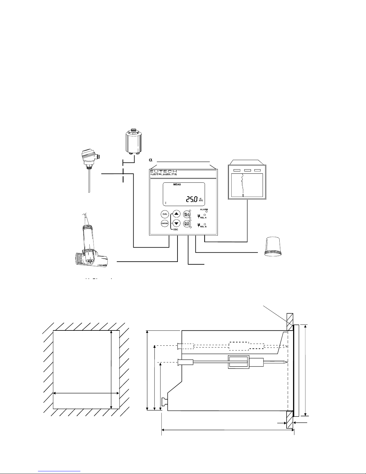
2.1 Measurement and Control System
A typical measurement system consists of:
• a αlpha-RES1000 process controller
• a suitable Resistivity electrode with the appropriate Cell constant and integrated temperature
sensor Pt 1000 or Pt 100,
• an immersion, flow or process assembly
• a final control element such as pump or valve and
• a chart recorder
2.2 Unit Dimensions
The field-tested control panel housing is 96 x 96 mm; with protection class IP 54 (front).
T
PowerMains
(
220/110 VAC
)
l
Flow
A
ssembl
y
to DosingPumps
P
r
ocessAssembl
y
ChartRecorde
r
Pt100/Pt1000
em
per
atureSenso
r
p
ha-RES1000 Controlle
r
Alarm/Sir
en
S
y
stem
m
Ω
Resistivity Controller
α
lpha RES 10 00
18.20
max. 175
max. 45
Mounting Cut-Out
Flat Gasket (1mm)
(TobeInsertedByCustomer)
Note: The Ta
p
ed CornersHavetoBeOnTo
p
92
32
56
96
92+ 0.5
92 + 0.5
Operating Instructions αlpha-RES1000
3
3 Electrical Connection
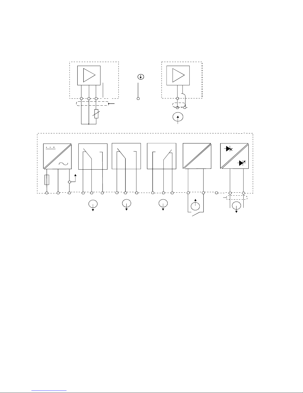
3.1 Connection Diagram
-
+
PE/S
P EA C : N L
1
2
5
4
3 6
7 8 9
10
11
12 13
14
15
1 7
15
1 6
* ) i n d i c a t e d c o ntact positions are for currentless conditions
Signal O u t p u t Hold Input
Alarm
Relay B
R
e l a y A
P o w e r M a i n s
RES
mA
Signal Input
Resistivity
S/
V
PE/S
RES
O
1 8 1 9 2 0
S/
Pt 1000/100
21 22
NC
Operating Instructions αlpha-RES1000
4
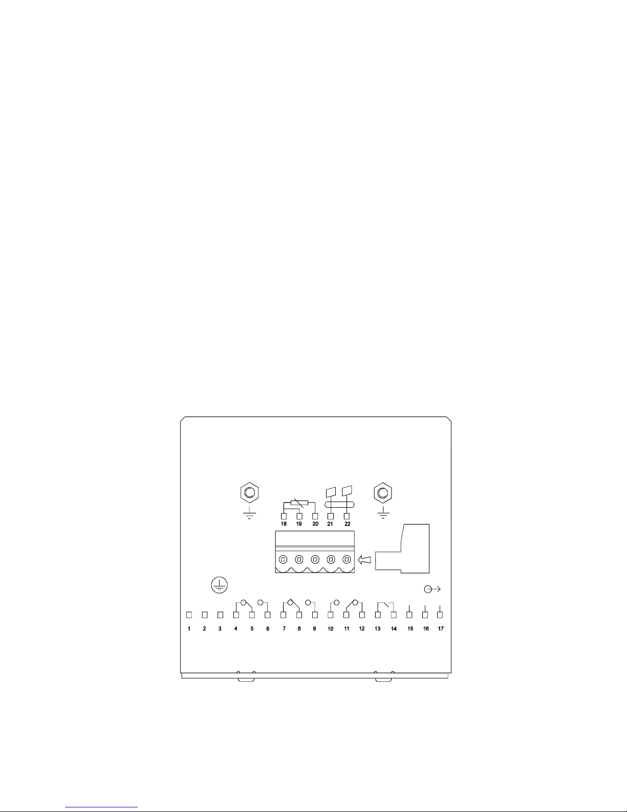
3.2 Back Panel
The back panel consists of two connectors. The first connector is the 17-way PCB edge connector and
the other is the 5-way connector.
Connection for the 17-way screw terminals (from left to right):
1. AC mains live wire 10. Alarm/Wash relay resting position (NO)
2. AC mains neutral wire 11. Alarm/Wash relay common
3. AC mains protective earth wire 12. Alarm/Wash relay working position (NC)
4. Relay 1 relay resting position (NC) 13. Hold function switch terminal 1
5. Relay 1 relay common 14. Hold function switch terminal 2
6. Relay 1 relay working position (NO) 15. No connection
7. Relay 2 relay resting position (NC) 16. 0/4 - 20 mA for -ve connection
8. Relay 2 relay common 17. 0/4 - 20 mA for +ve connection
9. Relay 2 relay working position (NO)
Connections for the 5-way screw terminals:
18. Pt1000/Pt100 lead 1 terminal (red)
19. Pt1000/Pt100 sense lead terminal (short 18 & 19 if using a two-wire system)
20. Pt1000/Pt100 lead 2 terminal (green)
21. Resistivity lead 1 (black)
22. Resistivity lead 2 (white)
*cable wire colours stated above are applicable to EC-CS10 series. For other electrodes, please check
electrode specifications.
IMPORTANT: The Alarm relay functions as an “Active Low” device i.e. it switches OFF under
Alarm condition. Therefore the Alarm display device should be connected to the ‘NC’ contacts of
the relay. If the relay is configured as “wash”, then it works in the ‘Active High’ mode. Therefore
the wash pump has to be connected across its “NO” contacts.
Pt100
/
RELAY1
LNPE
(F)
FUSE 250VAC
HOLD
ALARM
RELAY2
Pt1000
NC
-
+
cell
J2
100 mA
Operating Instructions αlpha-RES1000
5
4 Overview
4.1 Keypad and Display
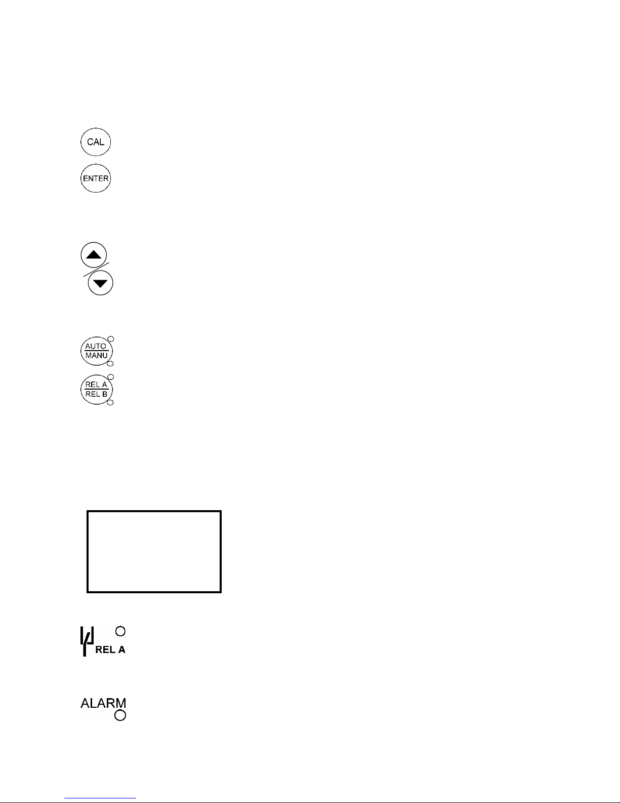
4.1.1 Keypad
•
Perform rapid calibration
•
Allows entry to Set up mode
• Select individual functions within the function group of Set up mode
• Store input data in the Set up mode
• Start calibration in the calibration mode
•
Select various function groups in the Set up mode.
• Set parameters and numerical values in sub functions of Set up mode
If pressed continuously, the setting speed increases
• Control the relays in the MANUAL function
• Return to the Measurement mode when both keys are pressed together
•
Switch between AUTO and MANUAL relay operation using a code
•
Display set-point values for the switch contacts in AUTO operation mode
• Switch between RELAY A and RELAY B in MANUAL relay operation mode
4.1.2 Display
The LCD display features two numerical display s that show status messages and meas ured values for
easy, quick reference. The display provides short-text information for setting parameters and
configuration.
• HOLD: Relay position and current output are frozen
• SETUP: Set-up mode of function groups
• MEAS: Measurement mode
• CAL: Calibration mode of Resistivity
• READY: Comes on after a successful calibration
• ATC: Comes on in the ATC mode. Disappears in the
Manual temperature Compensat ion mode. “ATC” flashes
if the temperature probe is faulty in its ATC mode
• Range No.: Indicates the measurement range selected
•
Display for RELAY A/B. Green LED indicates measured value within limit while
RED LED indicates measured value outside limit.
• Alarm display if limit value overshoot or the ATC connection is broken.
-8.8.8.8
HOLD SETUP MEAS CAL
READY
mΩ
o
C
8
 Loading...