

Page 1

Alpha RES 1000
Controller/Transmitter
Resistivity
Page 2

ROSS and the COIL trade dress are trademarks of Thermo Fisher Scientific Inc. U.S. patent 6,793,787.
AQUAfast, Cahn, ionplus, KNIpHE, No Cal, ORION, perpHect, PerpHecT, Per pHecTion, pHISA, pHuture,
Pure Water, Sage, Sensing the Future, SensorLink, ROSS, ROSS Ultra, Sure-F low, Titrator PLUS and
TURBO2 are registered trademarks of Thermo Fisher.
1-888-pHAX-ION, A+, All in One, Aplus, AQUAsnap, AssuredAccuracy, AUTO-BAR, AUTO-CAL, AUTO
DISPENSER, Auto-ID, AUTO-LOG, AUTO-READ, AUTO-STIR, Auto-Test, BOD AutoEZ, Cable-Free,
CERTI-CAL, CISA, DataCOLLECT, DataPLUS, digital LogR, DirectCal, DuraProbe, E nviro nmental Pro duct
Authority, Extra Easy/Extra Value, FAST QC, GAP, GLPcal, GLPcheck, GLPdoc, ISEasy, KAP,
LabConnect, LogR, Low Maintenance Triode, Minimum Stir Requirement, MSR, NISS, One-Touch, OneTouch Calibration, One-Touch Measurement, Optimum Results, Orion Star, Pentrode, pHuture MMS,
pHuture Pentrode, pHuture Quatrode, pHuture Triode, Quatrode, QuiKcheK, rf link, ROSS Resolution,
SAOB, SMART AVERAGING, Smart CheK, SMART STABILITY, Stacked, Star Navigator 21, Stat Face,
The Enhanced Lab, ThermaSense, Triode, TRIUMpH, Unbreakable pH, Universal Access are trademarks
of Thermo Fisher.
Guaranteed Success and The Technical Edge are service marks of Thermo Fisher.
PerpHecT meters are protected by U.S. patent 6,168,707. PerpHecT ROSS elec trodes are protected by
U.S. patent 6,168,707. ORION Series A meters and 9 00A printer are protected by U.S. pat ents 5,198,093 ,
D334,208 and D346,753.ionplus elec trodes and Optimum Results solutions are protec ted by U.S. patent
5,830,338.ROSS Ultra electrodes are protec ted by U.S. patent 6,793,787.ORP standard is protec ted by
U.S. patent 6,350,367. No Cal electrodes are protected by U.S. patent 7,27 6,142.© 2009 Thermo Fisher
Scientific Inc. All rights reserved. All trad emarks are the property of Thermo Fisher Scie ntific Inc. and its
subsidiaries.The specifications, descr iptions, drawings, ordering information and part numbers within this
document are subject to change without notice.This publication supersedes all previous publications on this
subject.
Page 3

Preface
This instruction manual serves to explain the use of the Alpha RES 1000 series Resistivity
controller/transmitter. The manual functions in two wa ys: firstly as a step by step guide to help the user
operate the instrument. Secondly, it serves as a handy reference guide. This instruction manual is writ ten
to cover as many anticipated ap plications of the Alpha RES 1000 Resi stivity controller/transmitter. If you
have doubts in the use of the ins trument, please do not hesita te to contact the nearest Thermo Scientific
Authorised Distributor.
The information presented in this m anual is subject to chan ge without notice as improve ments are made,
and does not represent a commitment on part of Thermo Fisher Scientific.
Thermo Fisher Scientific cannot accept any responsibility for damage or malfunction of the unit due t o
improper use of the instrument.
All rights reserved.
Page 4

TABLE OF CONTENTS
1 INTRODUCTION.................................................................................................1
1.1 DESCRIPTION OF UNIT ....................................................................................1
1.2 APPLICATIONS................................................................................................1
2 ASSEMBLY AND INSTALLATION.....................................................................2
2.1 MEASUREMENT AND CONTROL SYSTEM............................................................2
2.2 UNIT DIMENSIONS ..........................................................................................2
3 ELECTRICAL CONNECTION.............................................................................3
3.1 CONNECTION DIAGRAM...................................................................................3
3.2 BACK PANEL..................................................................................................4
4 OVERVIEW.........................................................................................................5
4.1 KEYPAD AND DISPLAY.....................................................................................5
4.1.1 Keypad................................................................................................................... 5
4.1.2 Display ................................................................................................................... 5
4.2 FUNCTION GROUPS ........................................................................................6
4.3 CONTROL CONCEPT .......................................................................................7
5 MEASUREMENT ................................................................................................8
5.1 ISPLAY IN MEASUREMENT MODE ....................................................................8 D
5.1.1 Check electrode performance................................................................................ 8
5.1.2 Checking set points................................................................................................ 8
5.2 ECURITY CODES...........................................................................................8 S
5.2.1 How to enter and change parameters in Calibration mode.................................... 8
5.2.2 How to enter and change parameters in Advanced Setup mode .......................... 9
6 CALIBRATION MODE......................................................................................10
6.1 RESISTIVITY CALIBRATION.............................................................................10
7 ADVANCED SET-UP MODE............................................................................10
7.1 TEMPERATURE COEFFICIENT SUB-FUNCTION...................................................11
7.1.1 Selecting Pure-water or Linear Temperature Coefficient..................................... 11
7.2 EMPERATURE CALIBRATION (ATC MODE ONLY)..............................................12 T
7.2.1 Setting manual temperature compensation ......................................................... 12
7.3 ONTROL RELAY A/CONTROL RELAY B (SP1/SP2) SUB-FUNCTION ..................13 C
7.3.1 Entering the Set point 1 (Set point 2) sub-function .............................................. 13
7.3.2 Selecting the set point values .............................................................................. 13
7.3.3 Choosing High or Low set points ......................................................................... 13
7.3.4 Selecting a hysteresis (dead band) value (0.000 to 0.200 m
Setting an on-delay time lag................................................................................. 14
7.3.5
7.3.6 Setting an off-delay time lag................................................................................. 15
Ω
or 0.00 to 2.00 m
Ω
)1 3
7.4 ONTROLLER (CNTR) SUB-FUNCTION .............................................................15 C
7.4.1 Entering the Controller sub-function..................................................................... 15
7.4.2 Choosing the controller type (limit or proportional) .............................................. 15
7.4.3 Choosing break/make contact relay type............................................................. 16
7.4.4 Selecting proportional range value Xp................................................................. 16
7.4.5 Maximum Pulse Length (tPL) or Maximum Frequency (FPF).............................. 17
Page 5

7.5 MEASUREMENT RANGE SUB-FUNCTION...........................................................17
7.5.1 Entering the Measuring Range sub-function........................................................ 17
7.5.2 Selecting Measuring Range sub-function ............................................................ 17
7.5.3 Measurement Range available in the Controller.................................................. 18
7.5.4 Current Output (rng) sub-function........................................................................ 18
7.5.5 Choosing the output type..................................................................................... 18
7.5.6 Selecting Resistivity value at 0(4)mA................................................................... 18
7.5.7 Selecting Resistivity value at 20mA..................................................................... 19
7.6 ONFIGURATION (CONF) SUB-FUNCTION ........................................................19 C
7.6.1 Entering Configuration sub-function..................................................................... 19
7.6.2 Selecting Filter Function and the Alarm or Wash Function.................................. 19
7.6.3 Selecting the alarm time lag (if the relay 3 is set to Alarm).................................. 20
7.6.4 Selecting steady or pulse contact for the alarm relay (if the relay 3 is set to Alarm)20
7.6.5 Wash Contact (if the relay 3 is set to Wash)........................................................ 20
7.6.6 Input Line Resistance Adjust................................................................................ 21
7.6.7 Reverting to factory default settings..................................................................... 21
7.7 ALIBRATION (CAL) SUB-FUNCTION ...............................................................21 C
7.7.1 Entering Calibration mode from Advanced Set-up mode..................................... 21
8 AUTO/MANUAL MODE....................................................................................22
8.1 AUTO MODE (MODE AFTER SWITCH-ON)...........................................................22
8.2 MANUAL MODE.............................................................................................22
9 TECHNICAL SPECIFICATIONS....................................................................... 23
10 GENERAL INFORMATION...........................................................................24
10.1 PACKAGING .................................................................................................24
10.2 RETURN OF GOODS......................................................................................24
10.3 GUIDELINES FOR RETURNING UNIT FOR REPAIR ..............................................24
11 APPENDICES...............................................................................................25
APPENDIX 1 – JUMPER POSITIONS.............................................................................25
APPENDIX 2 – CONDUCTIVITY / RESISTIVITY OF VARIOUS AQUEOUS SOLUTIONS AT 25OC26
APPENDIX 3 - SIMPLE EXPLANATION ON THE FUNCTION OF HYSTERESIS ........................26
APPENDIX 4 – PURE WATER CURVE...........................................................................27
Page 6

Operating Instructions Alpha RES 1000
1 Introduction
1.1 Description of Unit
Thank you for purchasing the Alpha ¼ DIN Alph a RES 1000 Resistivity process controllers. This unit is
used for measuring the Resistivity of a solution in meg a-ohms. You c an use this unit t o me asure Resis tivity
with limit control. This controller has many user-friendly and safety features which include:
• Menu-driven program that simplifies set-up
• Two ranges of Resistivity measurements-software selectable (Section 7.5.3).
• Built-in memory backup to ensure that calibration data and other information are not erased if
power supply fails
• Automatic temperature compensation (ATC) with Pt100 or Pt 1000
• Manual temperature compensation with independent setting for calibration and process
temperature
• Temperature coefficient variable between 0.00 to 10.00 % per
curve stored in memory. Reference temperature at 25
• 0 to 1999 second time delay adjustment on all relays – minimise false alarms
• Separately adjustable high and low set point hysteresis (dead bands) prevent chattering of relays
around the set points.
• Three control modes: limit, proportional pulse length or proportional pulse frequency.
• Large dual display LCD for easy reading with clear multiple annunciators, alarm status and
operational message annunciators
• Two switching contacts as set-point triggering relays and an alarm output relay
• Separate alarm relay alerts you when set points have exceeded the limits and if the Pt100/Pt10 00
wires are broken or disconnected during the ATC function
• Hold function freezes output current (0/4...20mA) and releases control relays
• LED indicators signal control activities to monitor controller status from a distance
Selectable Filter function stabilises rapid measurement changes.
• Protection against electromagnetic interference - galvan ically isolated 0/4.. 20mA output provides
safety for data logging and control purposes
1.2 Applications
Use this controller in panel mounted enclosures for applications in Pure water and R.O. Systems.
o
o
C. Separate pure water compensation
C.
1
Page 7
Operating Instructions Alpha RES 1000
A
A
p
p
2 Assembly and Installation
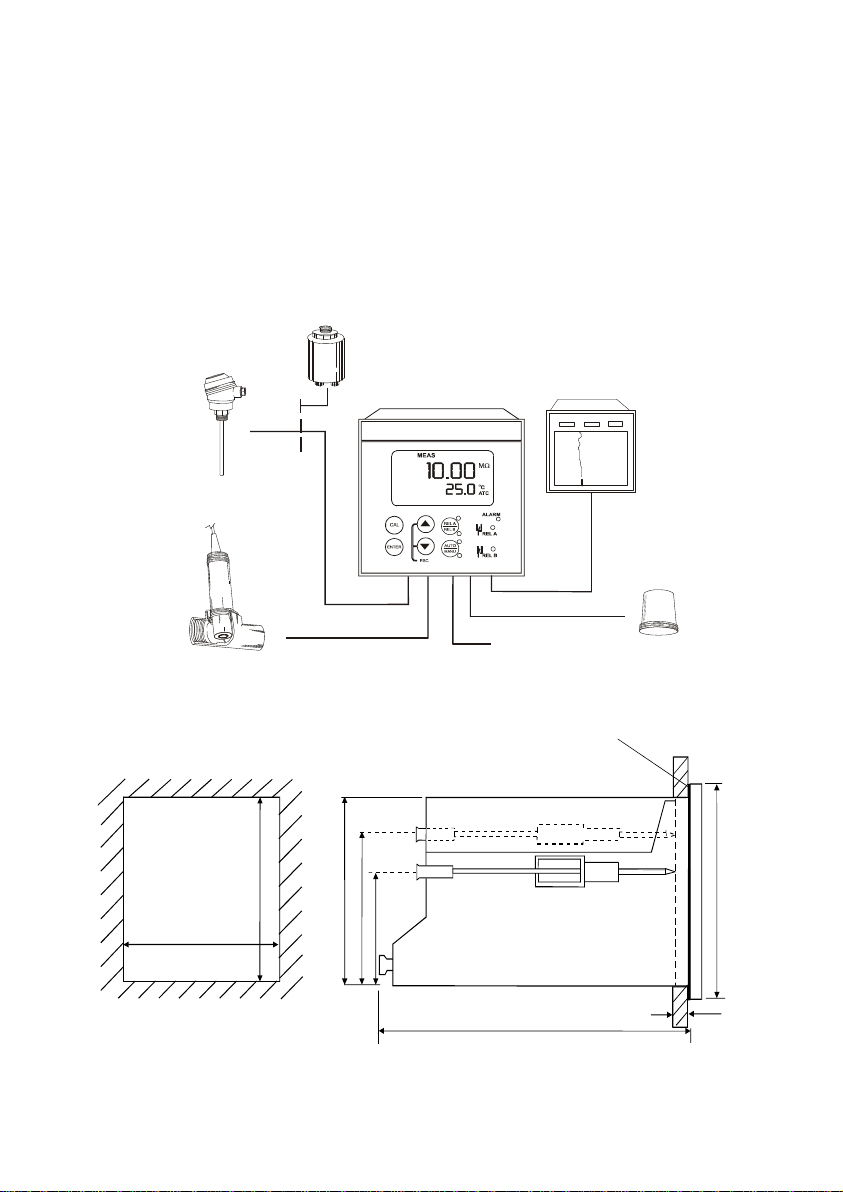
2.1 Measurement and Control System
A typical measurement system consists of:
• an Alpha RES 1000 process controller
• a suitable Resistivity electrode with the appropriate Cell constant a nd integrated temperature sensor Pt
1000 or Pt 100,
• an immersion, flow or process assembly
• a final control element such as pump or valve and
• a chart recorder
Flow Assembly
to Dosing Pumps
Pt100/Pt1000
Temperature Sensor
Process Assembly
with Electrode
2.2 Unit Dimensions
92+ 0.5
92+ 0.5
Mounting Cut-Out
The field-tested control panel housing is 96 x 96 mm; with protection class IP 54 (front).
92
56
Chart Recorder
rollerAlpha RES 1000 Cont
lpha RES 1000
larm / Siren
System
Power Mains
(220/110 VAC)
Flat Gasket (1mm)
(TobeInsertedByCustomer)
Note: The Ta
ed CornersHaveto BeOnTo
96
32
max. 175
max. 45
2
Page 8
Operating Instructions Alpha RES 1000
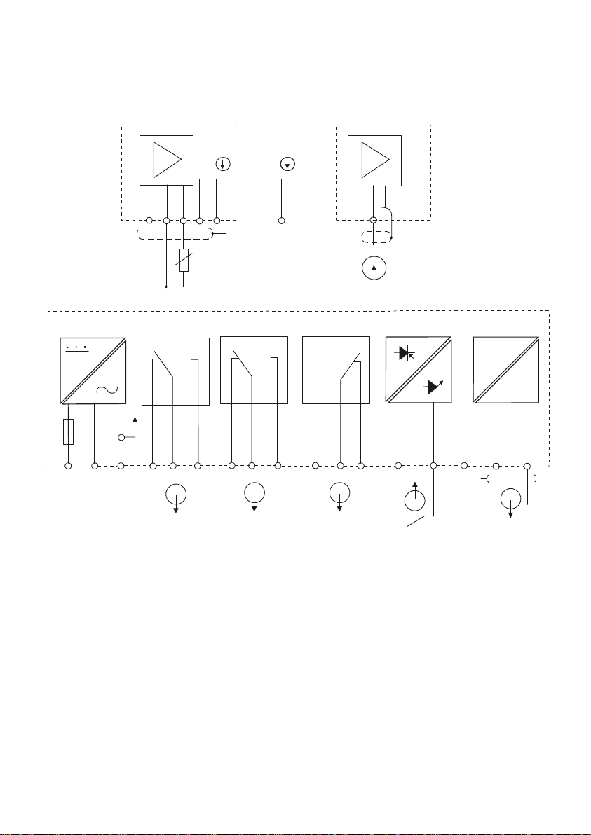
3 Electrical Connection
3.1 Connection Diagram
Res.
S/
V
S/S/
Power Mains
2
1
18 19 20
Pt100/Pt1000
36
PEAC: NL
4
Relay 1
5
21 22
PE/S
Relay 2
78 9
Signal Input Resistivi
Alarm
10
11
12 13
* ) indicated contact positions are for currentless or no er
ty
151715
14
PE/S
ror conditions
Signal Outputput Hold In
Res.
-
mA
+
16
3
Page 9
Operating Instructions Alpha RES 1000
/
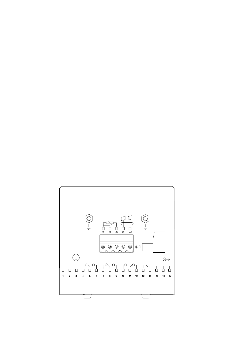
3.2 Back Panel
The back panel consists of two connectors. The first connector is the 17-way PCB edge connector and the
other is the 5-way connector.
Connection for the 17-way screw terminals (from left to right):
1. AC mains live wire 10. Alarm/Wash relay resting position (NO)
2. AC mains neutral wire 11. Alarm/Wash relay common
3. AC mains protective earth wire 12. Alarm/Wash relay working position (NC)
4. Relay 1 relay resting position (NC) 13. Hold function switch terminal 1
5. Relay 1 relay common 14. Hold function switch terminal 2
6. Relay 1 relay working position (NO) 15. No connection
7. Relay 2 relay resting position (NC) 16. 0/4 - 20 mA for -ve connection
8. Relay 2 relay common 17. 0/4 - 20 mA for +ve connection
9. Relay 2 relay working position (NO)
Connections for the 5-way screw terminals:
18. Pt1000/Pt100 lead 1 terminal (red)
19. Pt1000/Pt100 sense lead terminal (short 18 & 19 if using a two-wire system)
20. Pt1000/Pt100 lead 2 terminal (green)
21. Resistivity lead 1 (black)
22. Resistivity lead 2 (white)
*cable wire colours stated above are applicable to EC-CS10 series. For other electrodes, please check
electrode specifications.
IMPORTANT: The
Alarm relay functions
as an “Active Low”
device i.e. it switches
OFF under Alarm
condition. Therefore
the Alarm display
device should be
connected to the ‘NC’
contacts of the relay. If
the relay is configured
as “wash”, then it
+
works in the ‘Active
High’ mode. Therefore
the wash pump has to
be connected across
its “NO” contacts.
FUSE 250VAC
100 mA
(F)
LNPE
RELAY1
Pt100
Pt1000
RELAY2
cell
ALARM
J2
HOLD
-
NC
4
Page 10
Operating Instructions Alpha RES 1000
4 Overview
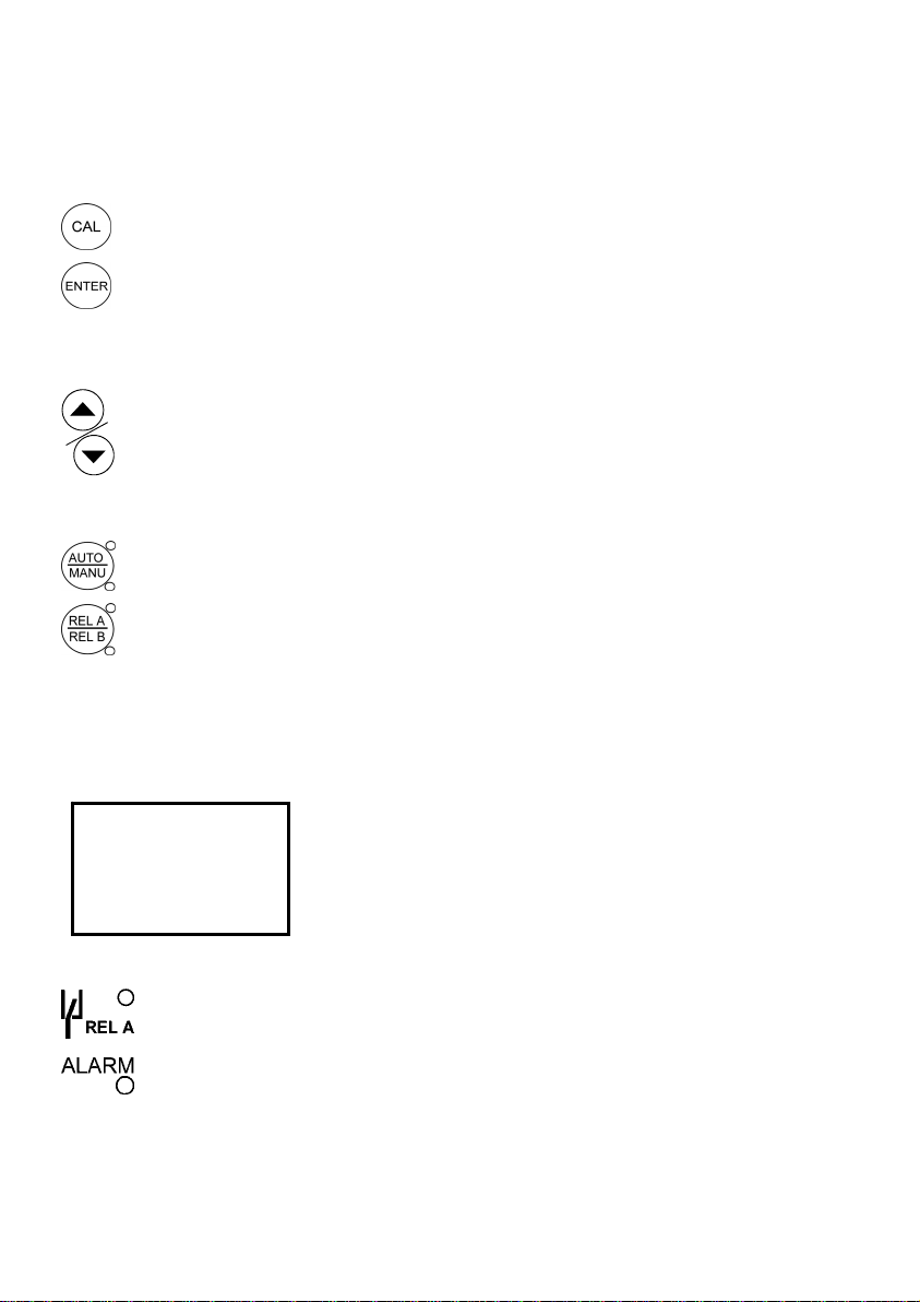
4.1 Keypad and Display
4.1.1 Keypad
•
Perform rapid calibration
•
Allows entry to Set up mode
• Select individual functions within the function group of Set up mode
• Store input data in the Set up mode
• Start calibration in the calibration mode
•
Select various function groups in the Set up mode.
• Set parameters and numerical values in sub functions of Set up mode
If pressed continuously, the setting speed increases
• Control the relays in the MANUAL function
• Return to the Measurement mode when both keys are pressed together
Switch between AUTO and MANUAL relay operation using a code
•
•
Display set-point values for the switch contacts in AUTO operation mode
• Switch between RELAY A and RELAY B in MANUAL relay operation mode
4.1.2 Display
The LCD display features two numerical displays that show status messages and measured val ues for easy,
quick reference. The display provides short-text information for setting parameters and configuration.
HOLD SETUP MEA
READY
-8.8.8.8
8
•
• Alarm display if limit value overshoot or the ATC connection is broken.
S CAL
Display for RELAY A/B. Green LED indicates measured value within limit while
RED LED indicates measured value outside limit.
• HOLD: Relay position and current output are frozen
• SETUP: Set-up mode of function groups
• MEAS: Measurement mode
mΩ
• CAL: Calibration mode of Resistivity
• READY: Comes on after a successful calibration
o
C
• ATC: Comes on in the ATC mode. Disappears in the
Manual temperature Compensation mode. “ ATC” flashes
if the temperature probe is faulty in its ATC mode
• Range No.: Indicates the measurement range selected
5
Page 11
Operating Instructions Alpha RES 1000
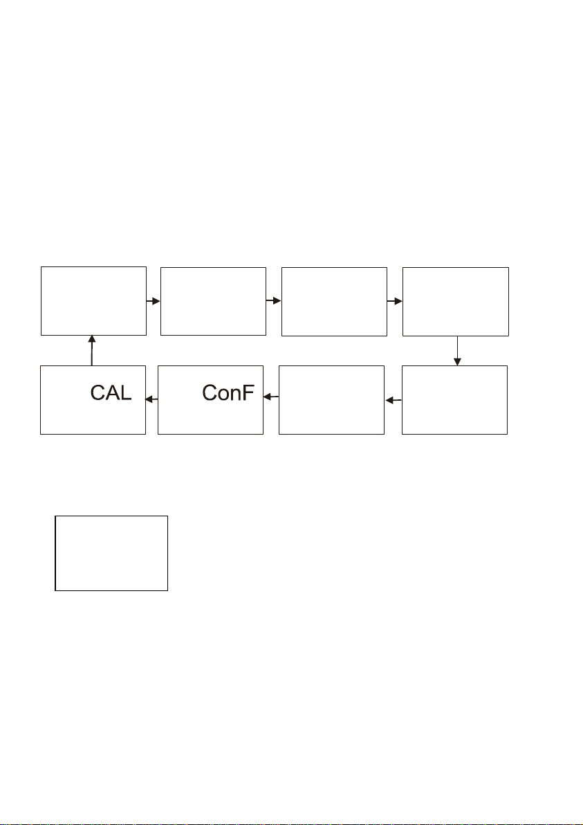
4.2 Function Groups
The main function and sub-function groups are organised in a matrix format for configuration and selection of
parameters. The main function groups are:
1) Temperature Coefficient settings (tC)
2) Temperature Measurement / compensation settings (SEt
3) Control relay 1 configuration (SP1)
4) Control relay 2 configuration (SP2)
5) Control type (Cntr)
6) Current output (rng)
7) Configuration (ConF)
8) Calibration (CAL rES)
HOLD
SETUP
HOLD
SETUP
HOLD
SETUP
o
C)
HOLD
SETUP
SETUP
SEt
o
C
HOLD
tc
SETUPHOLD
HOLD SETUP
SP1
rng
HOLD
SP2
SETUP
Cntr
rES
Set-up parameters can be viewed or changed by entering a security code. See Section 5.2 for security code
information.
4.2.1 How to view operating parameters without access to change them:
000
S.Cd
d) Press ENTER key at a particular sub-function to view in detail.
e) Press ENTER key to return to sub-function menu.
f) Press Δ and ∇ keys simultaneously (Escape key) at any time to return to Measurement mode.
Note: To simplify operations, the controller will n ot display parameters t hat are not releva nt to a particular subfunction.
a) Press ENTER key. Display will prompt to enter security code (S.Cd).
Leave security code at “000” (do not enter a security code).
b) Press ENTER key again. This allow s for viewing (not change) any sub-
functions’ settings.
c) Press Δ or ∇ keys to scroll through sub-functions.
6
Page 12

Operating Instructions Alpha RES 1000
4.3 Control Concept
The main function and sub-function groups are organ ised in a m atrix format as shown below. These functions
can be accessed via the front keypad for configuration and selection of parameters.
Controller offers three levels of password pr otection: (1) for viewing all SE TUP Configurati on without the faci lity
to make changes; (2) for direct access to calibration functio n; and (3) for setting or editing specific controller
parameters or functions in SETUP mode.
Note: Passwords are not user-defined and are s et by factory. Please keep passwords confidential to avoid
unauthorised tampering of the system.
7
Page 13

Operating Instructions Alpha RES 1000
5 Measurement
5.1 Display in Measurement mode
When controller is powered on, it automatically enters into the Measurement mo de after large dual LCD briefly
displays all segments.
The upper display shows the measured Resistivity value, while lower display shows temperature value.
Annunciators at right side of the dis play indicate mΩ and
side of the display shows current status of controller, e.g. “HOLD”, “SETUP”, “MEAS”, “CAL”, “READY”, etc.
5.1.1 Check electrode performance
To read current electrode condition without changing them:
1) Press the CAL key followed by the ENTER key without adjusting the security code (leave code at “000” ).
The upper display shows the last cell constant as a percentage with the lower displ ay shows “CEL” . Press
ENTER key and the next upper display shows the last calibration factor.
Note: If security code is changed to a value other than “000”, pressing ENTER key will return to
Measurement mode, without displaying electrode information.
2) Press ENTER key a second time to return to Measurement mode.
5.1.2 Checking set points
To read current set point values without changing them:
Press RELAY Selection (Rel A / Rel B) key. Upper display shows set poi nt for Relay A; l ower display show s
“SP1”.
After two seconds upper display shows set-point value for Relay B; lower display shows “SP2”.
After an additional two seconds, controller returns to Measurement mode.
5.2 Security Codes
Two levels of security protection with separate securi ty codes are provided. First level allows entry into the
Calibration mode: security code = 11; second allows entry into SETUP mode: security code = 22.
Security codes protect controller from unauthorised tampering. Parameters cannot be changed unless the
security code is entered.
5.2.1 How to enter and change parameters in Calibration mode
1) Press CAL key. Upper display shows “000” and lower display
shows “C.Cd” to prompt for Calibration security code.
2) Press Δ or ∇ ke ys to scroll upper display to Calibration security
code “11”.
3) Press ENTER key. Display shows “CAL RES”.
4) Press ENTER again to begin calibration. Refer to Section 6 for full details on calibration.
5) Press Δ and ∇ keys simultaneously (escape) to return to Measurement mode.
NOTE: To view (not change) electrode condition, push ENTER key when the security code reads “000”.
o
C. Similarly annunciators or icons at the top or left
1 1
C.Cd
8
Page 14

Operating Instructions Alpha RES 1000
5.2.1.1 Clearing Calibration security code from display
The calibration security code automatically resets from “11” to “000” after returning to Measurement mode.
5.2.2 How to enter and change parameters in Advanced Setup mode
1) Press ENTER key once. Upper display shows “000” and lower display shows “S.Cd” to prompt for
Advanced Setup security code.
2) Press Δ or ∇ keys to scroll displa y to Setup security code “22” . NOTE: Pressing ENTER key at a value
other than “22” causes the controller to revert to Measurement mode.
3) Press ENTER key.
4) Upper display reads “tc”. You are now in the Advanced Setup mode. See Section 7 for complete
instructions. To return to Measurement mode, press Δ and ∇ keys simultaneously (escape).
NOTE: If to view (not change) set up parameters, push ENTER key when security code reads “000”.
5.2.2.1 Clearing Advanced Setup security code from display
Having entered the security code and r eturned to the Measurement mo de, security code “22” s till appears on
display whenever ENTER key is pressed. To conceal the sec urity code, it must be manually reset. To clear
Advanced Setup security code from display:
1) Press ENTER key in Measurement mode.
2) Set to any security code (not 11 or 22) and complete by pressing ENTER.
NOTE: When you enter the Calibration mode with code “ 11” or Advanced Setup mode with security c ode
“22”, unit automatically enters into HOLD mod e until you return back to Measurement mode. T he HOLD
annunciator is displayed at the upper left of t he display. While on HOLD, current (0/4..20mA) output is
frozen and set point relays are deactivated.
9
Page 15

Operating Instructions Alpha RES 1000
6 Calibration Mode
Calibration mode can be accessed directly from Me asurement mode by pressing CAL key and entering the
Calibration security code; or from the Advanced Setup mode.
6.1 Resistivity Calibration
Calibration is always carried out in the specific ran ge selected. The Resistivity Controller allows a one-point
calibration.
1) Enter Calibration mode. While in Measurement mode, press CAL
HOLD SETUP
1
HOLD CAL
100.0
1
HOLD C
18.20
25.0
1
HOLD CAL
CAL
S rE
CEL
AL
mΩ
oC
ATC
1.01
FCt
1
calibration error, the controller displays “ERR” annunciator. To recalibrate repeat step 3. To exit from
calibration, push both Δ and ∇ keys (escape) to resume to Measurement mode.
5) Press ENTER key. If you entered calibration mode using CAL key, control ler will return to Measureme nt
mode. If you entered calibration mode from Advanc ed Set-up mode, controller will return to sub-function
menu.
Note: When calibrating with manual te mperature compensation, controller a utomatically changes from preset
process temperature to calibration t emperature. After leav ing the Calibratio n mode, contr oller switches back to
process temperature (for setting calibration temperature and process temperature, see section 7.2).
key and scroll to Calibration code “11”. Press ENTER key. The
upper display reads “CAL” and lower display, “rES”.
2) Press the ENTER key. The controller displays its last set Cell
Constant (k) of the cell as a percentage of the theoretical value.
Using the up and down key, the value can be s et to anywhere from
80 to 120%. Press the ENTER key again to carry out calibration.
3) Immerse the Conductivity cell in a suitable standard solution,
%
whose value is within the measurement range selected in the
controller. Agitate the Cell in the sol ution to r emove any trapped a irbubbles. Note: The calibration standard should hav e a value that is
between 20% to 100% of the range sel ected. For example, if the
range in the controller is selected to be 19. 99 mΩ (range 1), then
the calibration standard value should be 4.00 mΩ to 19.99 mΩ.
4) Once the reading has stabilized, use the Δ or ∇ keys to adjust the
measured value to that of the sta ndard solution. Press the ENTER
key to accept the value and the controller displays the revised
condition of the probe The lower display shows the factor “FCt”
while the upper display shows the ratio of ideal to adjusted
calibration value.
Note: The acceptable calibration window is ±40% of the displayed
(default) value. If the displayed is 10.00 mΩ standard, the values to
which it can be adjusted is 6.00 to 14.00 mΩ. If there is a
7 Advanced Set-Up Mode
10
Page 16

Operating Instructions Alpha RES 1000
7.1 Temperature Coefficient sub-function
This sub-function allows you to sele ct correct temperature coeff icient for optimum opera tions. For application s
in pure water or ultra-pure water industries, select “Pur” temperature coefficient option. For all other applications,
select “Lin” temperature coefficient. Controller allows further input of temperature coefficient values,
independently for process and for calibrating solutions. Default is “Pur”.
HOLD SETUP
tc
HOLD SETUP
Lin
tC
HOLD SETUP
2.10
P.tC
%
ATC
HOLD SETUP
2.10
C.tC
%
ATC
HOLD SETUP
Pur
tC
7.1.1 Selecting Pure-water or Linear Temperature Coefficient
1) Enter Advanced set-up mode. Push ENTER key and scroll to
Advanced Set-up security code “22”. Push ENTER key. Controller
displays “tC”. Press ENTER key again. Controller displ ays “Pur” in upper
display and “tC” in lower display. Default is “Pur”.
2) Press Δ or ∇ keys to select between “Pur” and “Lin” temperature
coefficients. If “Lin” tC is to be selected, press ENTER key when
controller displays “Lin”.
3) If “Lin” is selected, upper display shows “2.10%”, while lower display
show “P.tC”. This option allows input of Process Te mperature co efficient,
from 0 to 10%. Default is 2.10%. Use Δ or ∇ keys to enter required
temperature coefficient value.
4) Press ENTER key. Next, enter the calibration solution temperature
coefficient value, “C.tC”, from 0 to 10%. Default is 2.10%.
5) Press Δ or ∇ keys to input desired calibration solution temperature
coefficient.
6) Press ENTER key to accept.
7) Continue with additional Advance setup procedures or return to
Measurement mode by pressing Δ and ∇ keys (escape) simultaneously.
HOLD SETUP
tc
HOLD SETUP
Lin
tC
HOLD SETUP
2.10 %
P.tC ATC
HOLD SETUP
2.10 %
C.tC ATC
11
Page 17

Operating Instructions Alpha RES 1000
7.2 Temperature calibration (ATC mode only)
1) Enter Advanced Set-up mode. Push the ENTER key and scroll to
Advanced Set-up security code “22”. Push the ENTER key again.
2) Press the Δ or ∇ keys to scroll through the sub-menus until the d isplay
shows “Set
3) Press the Δ or ∇ keys to scroll until the upper display shows “ ATC”, and
the lower display shows “on”. Default setting is “ATC on”.
4) Press the ENTER key. In this mode, the ATC probe can be calibrated. The
upper display indicates the current t emperature offset. The current measured
temperature is shown in the lower display.
5) Compare the current measured temperature on the c ontroller display to a
thermometer known to be accurate. Note down the correct temperature value.
6) Press the Δ or ∇ keys to scroll the lower display to match the correct value.
The upper display will now show the offset value. You can offs et temperature
up to ± 10
7) Press the ENTER key to confirm your selection.
8) Continue with additional Advanced Set-up procedures, or return to the
Measurement mode by pressing the Δ and ∇ keys (escape) simultaneously.
7.2.1 Setting manual temperature compensation
HOLD SETUP
HOLD SETUP
HOLD SETUP
6) Press Δ or ∇ keys to adjust calibration temperature value, –9.9 to 125
7) Continue with additional Advanced Set-up procedures, or return to Measurement mode by pressing Δ and
∇ keys (escape) simultaneously.
o
C”. Press the ENTER key.
o
C.
Note: This parameter is unavailable if ATC is selected.
oFF
Atc
For manual temperature compensation, two di fferent temperatur es: proce ss and
calibration can be input independently. Example: setting a calibration
temperature of 25
even if process temperature is different.
1) Enter Advanced set-up mode. Push ENTER key and scroll to Advanced
25.0
P.C
25.0
C.C
2) Pressing the Δ or ∇ keys keys toggle between ATC ‘on’ or ‘off’ (default
3) Press ENTER key. Upper display shows current process temperature and
4) Press Δ or ∇ keys to adj ust process temperature v alue from –9.9 to 125
5) Press ENTER key. Upper display shows current calibration te mperature
o
C lets you calibrate using standard buffer solutions at 25 oC,
Set-up security code “22”. Push ENTER key and Press Δ or ∇ keys to
scroll till display shows “Set oC”. Press ENTER.
setting is ATC on). Select “ATC off”.
lower display shows “P.
o
C.
and lower display shows “C.
o
C” to indicate process temperature.
o
C” to indicate calibration temperature.
HOLD SETUP
HOLD SETUP
HOLD SETUP
o
C. Press ENTER key.
Set
o
C
on
Atc
0.0
25.0
o
C
ATC
12
Page 18

Operating Instructions Alpha RES 1000
7.3 Control Relay A/Control Relay B (SP1/SP2) sub-function
SP1 option sets operating parameters for Relay A; and SP2 for relay B. Since these gro ups have the same
set-up parameters, they are described together.
On.d
HOLD SETUP HOLD SETUP HOLD SETUP HOLD SETUP HOLD SETUP HOLD SETUP
0
0
Of.d
SP 1
1.00
SP 1
Lo
SP 1
0.20
HYS
7.3.1 Entering the Set point 1 (Set point 2) sub-function
1) Enter Advanced Set-up mode. Push the ENTER key and
scroll to Advanced Set-up security code “22”. Push the
ENTER key again.
2) Press the Δ or ∇ keys to scroll until the upper display
shows SP1 (SP2).
7.3.2 Selecting the set point values
This lets you choose the value that will ca use your controller to
activate (Default: SP1 = 1.00 mΩ; SP2 = 19.00 mΩ).
1) Follow directions in 7.3.1 to enter Control Relay mode. If
you are in this mode, skip to step 2.
2) Press the ENTER key. The upper display shows the
current set point value and the lower display shows SP1
(SP2).
3) Press the Δ or ∇ keys to select your value for Set point 1
(Set point 2). Your controller will activate at the v alue you
select.
4) Press the ENTER key to confirm your selection.
5) Proceed to 7.3.3, or return to Measurement mode by pressing the Δ and ∇ keys simultaneously (escape).
HOLD SETUP
HOLD SETUP
HOLD SETUP
SP 1
1.00
SP 1
Lo
SP 1
mΩ
7.3.3 Choosing High or Low set points
When ‘Lo’ is selected, the control relay is ac tivated when the value is lower than SP1 (SP2). When ‘Hi’ is
selected, the control relay is activated whe n the value is higher than the set point (SP1/SP2). Using both SP 1
and SP2, you can select lo/lo, lo/hi, hi/lo, or hi/hi set points (Default: SP1 = Lo; SP2 = Hi).
1) Follow directions in 7.3.1 to enter Control Relay mode.
2) Press the ENTER key until the upper display shows Lo or Hi (for low or high set point) and the lower
display shows SP1 (SP2).
3) Press Δ or ∇ keys to select low (lo) or high (hi) set point for SP1 (SP2). Press ENTER key.
4) Proceed to 7.3.4, or return Measurement mode by pressing Δ and ∇ keys simultaneously (escape).
7.3.4 Selecting a hysteresis (dead band) value (0.000 to 0.200 mΩ or 0.00 to 2.00 mΩ)
Hysteresis prevents rapid contact switching if the value is fluctuating near the set point. It does this by
overshooting the set point value to a spec ified hysteresis value (default is 0.20 mΩ). You can set the hysteresis
value from 0.000 to 0.200 mΩ or 0.00 to 2.00 mΩ.
13
Page 19

Operating Instructions Alpha RES 1000
Example: Set point 1 (Lo) is at 1.00 mΩ and hysteresis limit value is at 0.20 mΩ. If measured value
undershoots low set point of 1.00 mΩ, relay activ ates, which in turn activates an external device such as a
pump or valve. Actions of the external d evice will caus e the value to r ise above 1.00 mΩ. When the value has
increased to 1.20 mΩ, relay, and hence the pump will switch off.
HOLD SETUP
20
HYS
4) Press ENTER key to confirm your selection.
5) Proceed to 7.3.5, or return to Measurement mode by pressing the Δ and ∇ keys simultaneously (escape).
NOTE: Please refer to Appendix 4 for a graphical representation of the Hysteresis
1) Follow directions in 7.3.1 to enter Control Relay mode.
2) Push the ENTER key. The upper display shows the hysteresis (dead
μS
band) value and the lower display shows “HYS”.
3) Press Δ or ∇ keys to enter hyster esis value for Set point 1 (Set point 2).
Controller will activate at the value s elec te d. Note: All settings for SP1 and
SP2 are completely independent of each other.
.
7.3.5 Setting an on-delay time lag
You can set as time delay for each relay, which sto ps the relay from switching on the moment the set point is
exceeded. This controller lets you set a 0 to 1999 seconds time delay before the relay activates.
HOLD SETUP
0
On.d
4) Press the ENTER key to confirm your selection.
5) Proceed to 7.3.6, or return to Measurement mode by pressing the Δ and ∇ keys simultaneously (escape).
1) Follow directions in 7.3.1 to enter Control Relay mode.
2) Push the ENTER key. The upper display shows “0” time and the lower
display shows “On.d”.
3) Press the Δ or ∇ keys to enter on-delay time for Set point 1 (Set point
2). The controller will delay activation for the number of seconds (0 to
1999) you select.
14
Page 20

Operating Instructions Alpha RES 1000
7.3.6 Setting an off-delay time lag
You can set as time delay for each relay, which stops the relay from switching off the moment the value
reached the set point and hysteresis. This controller lets you set a 0 to 1999 seconds ti me delay before your
relay deactivates.
1) Follow directions in 7.3.1 to enter Control Relay mode.
2) Push the ENTER key. The upper display shows “0” time and the
lower display shows “OF.d”.
3) Press the Δ or ∇ keys to enter on-delay time for Set point 1 (Set
point 2). Controller will delay activation f or the number of seconds
(0 to 1999) selected (Default off delay is 0).
4) Press the ENTER key to confirm your selection.
5) Continue with Advanced Set-up mode procedures, or return to Measurement mode by pre s s ing th e Δ and
∇ keys simultaneously (escape).
HOLD SETUP
0
OF.d
7.4 Controller (Cntr) sub-function
You can set the controller’s parameters in this sub-function.
7.4.1 Entering the Controller sub-function
1) Enter Advanced Set-up mode. Push ENTER key and scroll to Advanced set-up security code “22”.
Push ENTER key.
2) Press Δ or ∇ keys to scroll until upper display shows “Cntr”.
HOLD SETUP
Cntr
L.Ct
tYP
HOLD SETUP
oFF
tYP
HOLD SETUP
PLC
tYP
HOLD SETUP
PFC
tYP
7.4.2 Choosing the controller type (limit or proportional)
This mode lets you choose your con troller type: li mit control, pu lse length pr oportional con trol, pulse freq uency
proportional control, or control off.
- Use limit control with pumps or values for fast response.
- Use pulse frequency proportional control to operate your pumps smoothly.
- Use pulse length proportional control for precise control of proportioning valves.
- Use control off to operate controller as a monitor only or to keep relays from switching.
15
Page 21

Operating Instructions Alpha RES 1000
1) Follow directions in 7.4.1 to enter Controller mode.
2) Press the ENTER key. The upper display shows the current contr oller type and the lower disp lay shows
“tYP”.
3) Press the Δ and ∇ keys to select your controller type.
- L.Ct = limit value pickup (on/off control).
- oFF = controller off.
- PLC = pulse length control.
- PFC = pulse frequency control.
4) Press the ENTER key to confirm your selection.
5) Proceed to 7.4.3 step 3, or return to Meas urement mode by press ing the Δ and ∇ keys simultaneously
(escape).
7.4.3 Choosing break/make contact relay type
Note: If the controller type “oFF” is set, the parameters listed in 7.4.4 and 7.4.5 are blanked out.
This mode lets you determine the relay-state under Non-Alarm condition – dEEN (de-energised) or EN
(energised).
HOLD SETUP
dEEn
rEL
HOLD SETUP
En
rEL
Note: If the controller type “oFF” or “L.Ct” is set, the parameters listed in 7.4.4 and 7.4.5 are blanked out.
This mode lets you set a band as a percentage of its full scale value. You can select this range from 10 to
200%, and the lower display shows “PrP”.
HOLD SETUP
100
PrP
5) Proceed to 7.4.5 step 3, or return to Measurement mode by pressing t he Δ and ∇ keys simultaneously
(escape).
1) Follow directions in 7.4.1 to enter Controller mode.
2) Press the ENTER key. Scroll until the lower dis play shows “ rEL” and th e
upper display shows the current selection (de-energised = dEEN or
energised = EN).
3) Press the Δ or ∇ keys to choose de-energised or energised relay state.
4) Press the ENTER key to confirm your selection.
5) Continue with Advanced Set-up mode procedures, or return to
Measurement mode by pressing the Δ and ∇ keys simultaneously
(escape).
7.4.4 Selecting proportional range value Xp
1) Follow directions in 7.4.1 to enter Controller mode.
2) Press the ENTER key. Scroll until the upper display shows the
proportional range (a number from 10 t o 200%), and the lower dis play
shows “PrP”.
3) Press the Δ and ∇ keys to choose the proportional range value Xp.
4) Press the ENTER key to confirm your selection.
16
Page 22

Operating Instructions Alpha RES 1000
g
7.4.5 Maximum Pulse Length (tPL) or Maximum Frequency (FPF)
Note: If the controller type “oFF” or “L.Ct” is set, the parameters listed in 7.4.4 and 7.4.5 are blanked out.
This mode lets you set the maximum pulse length or the maximum frequency at which the relay will operate.
HOLD SETUP
HOLD SETUP
10.0
t.PL
60
F.PF
1) Follow directions in 7.4.1 to enter Controller mode.
2) Press the ENTER key. Scroll until the lower display shows “t.PL” or
“F.PF”.
- In PLC (pulse length) mode: The lower display shows “t.PL” to indic ate
pulse length. The upper display shows y our current pulse length. You
can select any value from 0.5 to 20 seconds.
- In PFC (pulse frequency) mode: The lower display shows F.PF to
indicate pulse frequency. The upper display shows your current
maximum pulse rate. You can select any value from 60 to 120 pulses
per minute. When the measured value ex ceeds the Proportional Band
in 7.4.4, the controller will pulse the relay at this rate.
3) Press the Δ and ∇ keys to choose the period duration or maximum
frequency, depending on your mode.
4) Press the ENTER key to confirm your selection and to return to
Advanced Set-up mode, or return to Measur ement mode by pressing the
Δ and ∇ keys simultaneously (escape).
7.5 Measurement Range sub-function
In this sub-function, appropriate range is selected with the appropriate cell constant.
7.5.1 Entering the Measuring Range sub-function
1) Enter Advanced Set-up mode. Push ENTER key and scroll to Advanced Set-up security c ode “22”.
Push ENTER key.
2) Press Δ or ∇ keys to scroll until upper display shows “rng”.
HOLD SETUP
HOLD SETUP
1
rn
20.00
0.01
7.5.2 Selecting Measuring Range sub-function
1) Follow directions in 7.5.1 to enter Controller mode and press ENTER
key.
2) Press Δ or ∇ ke ys to select correct range. (Please refer to 7.5.3 for full
list of measurement ranges). Note the upper display shows maximum
measurement range, while lower display shows Cell constant. Lower le ftcorner of LCD displays the number corresponding to the respective range.
3) Press ENTER key to confirm.
mΩ
4) Proceed to 7.5.4 to set current output or return to Measurement mode by
pressing Δ and ∇ keys simultaneously (escape).
17
Page 23

Operating Instructions Alpha RES 1000
7.5.3 Measurement Range available in the Controller
Range No. Range Resolution Default cell K
1
2
0.000 – 19.99 mΩ 0.01 mΩ
0.00 – 1.999 mΩ 0.001 mΩ
0.01
0.1
7.5.4 Current Output (rng) sub-function
This sub-function lets you set the transmitter current output range of this unit. The difference between the upper
and lower range has to be a minimum of 20% of Full Scale, anywhere on the scale.
1) Follow directions in 7.5.2 to enter Controller mode.
2) Press ENTER key. Please refer to 7.5.5 for current output
sub-function.
7.5.5 Choosing the output type
This parameter lets you choose between 0-20 mA or 4-20 mA
output.
1) Follow directions in 7.5.4 to enter Current Output mode.
2) Scroll with the ENTER key until the upper display shows the
output type (0-20 or 4-20), and the lower display shows “out”.
3) Press the Δ or ∇ keys to select your output type: 0-20 or 4-20
mA.
4) Press ENTER key to confirm your selection.
5) Proceed to 7.5.6, or return to Measurement mode by pressing
the Δ and ∇ keys simultaneously (escape).
1
1
HOLD SETUP
HOLD SETUP
HOLD SETUP
1
4-20
out
0.00
r.4
20.00
r.20
mΩ
mΩ
7.5.6 Selecting Resistivity value at 0(4)mA
This parameter selects the resistivity value at which transmitter output will be 0(4) mA. Follow directions in
7.5.4 to enter Current Output mode.
1) Press ENTER key until upper display shows a resistivity value and lower display shows “r.0(4)”.
2) Press Δ or ∇ keys to select required resistivity value t o be equivalent to 0(4) (Default is 0.00 m
Please note that difference between value at 4mA and 20mA must be at least 20% of F.S. Press ENTER
key.
3) Press ENTER key to return to Advanced Set-up mode, or return to Measurement mode by pressing Δ
and ∇ keys simultaneously (escape).
Ω
).
18
Page 24

Operating Instructions Alpha RES 1000
7.5.7 Selecting Resistivity value at 20mA
This parameter selects the resistivity value at which transmitter output will be 20mA.
4) Follow directions in 7.5.4 to enter Current Output mode.
5) Press the ENTER key until upper display shows a resistivity value and lower display shows “r.20”.
6) Press the Δ or ∇ keys to select the required resistivity value to be equ ivalent t o 20 mA (Default is 20.00
mΩ).Note that difference between the value at 4mA and 20mA must be at least 20% of F.S.
7) Press the ENTER key to confirm your selection.
8) Press the ENTER key to return to Advanced Set-up mode, or return to Measur ement mode by pressing
the Δ and ∇ keys simultaneously (escape).
7.6 Configuration (ConF) sub-function
This group of parameters lets you configure the controller to suit your requirements.
7.6.1 Entering Configuration sub-function
1) Enter Advanced Set-up mode. Push ENTER key and scroll to Advanced Set-up security c ode “22”.
Push ENTER key.
2) Press Δ or ∇ keys to scroll until upper display shows “ConF”. Press ENTER key to enter configuration
sub-function.
7.6.2 Selecting Filter Function and the Alarm or Wash Function
In this configuration sub-function, y ou have the ‘F ilter’ selectio n which lets you filter
rapid measurement changes and stabilisin g the measurement. This configuration
sub-function also allows you to use the A larm relay as Was h or Clean contact. The
Wash (Clean) contact is used in combination with automatic cleaning systems.
During the wash cycle, the analog output is set on hold.
1) In Filter selection mode, use the arrow keys to choose filter "on" or "off".
2) Press the ENTER key to confirm. Display will now show “ALr” or “CLn”.
3) Press the Δ or ∇ keys to choose "ALr" (Alarm) or "CLn" (Clean) function.
4) Press the ENTER key to confirm your selection.
5) Proceed to 7.6.3, or return to Measurement mode by pressing the Δ and ∇ keys
simultaneously (escape).
Note: The factory default setting for the Filter selection is "on".
19
Page 25

Operating Instructions Alpha RES 1000
7.6.3 Selecting the alarm time lag (if the relay 3 is set to Alarm)
This parameter group lets you select a period of time before the alarm activates when your set point has been
overshot. You can select from 0 to 1999 seconds.
HOLD SETUP
30
AL.d
7.6.4 Selecting steady or pulse contact for the alarm relay (if the relay 3 is set to Alarm)
This parameter group selects whether a larm con tact w ill operat e as a s teady c ontac t or a f leeti ng (sing le pu lse)
contact. Pulse contact closing time is 1 second.
1) Follow directions in 7.6.1 to enter Configuration mode. Press
ENTER key until the upper display shows “Stdy” or “FLEt” and
lower display shows “AL.C.”.
AL.C = alarm contact
StdY = steady contact
FLEt = fleeting (single pulse) contact
2) Press Δ or ∇ keys to select steady or pulse contact. Press
ENTER key.
3) Proceed to 7.6.5, or return to Measurement mode by pressing Δ
and ∇ keys simultaneously (escape).
1) Follow directions in 7.6.1 to enter Configuration mode.
2) Press the ENTER key until the upper display shows a num erical value
(in seconds) and the lower display shows “AL.d”.
3) Press the Δ or ∇ keys to select how long of an alarm delay (0 to 1999
seconds) you want.
4) Press the ENTER key to confirm your selection.
5) Proceed to 7.6.4, or return to Measurement mode by pressing t he Δ and
∇ keys simultaneously (escape).
HOLD SETUP
Stdy
AL.C
HOLD SETUP
FLEt
AL.C
7.6.5 Wash Contact (if the relay 3 is set to Wash)
HOLD SETUP
CLn
rL3
1) Follow directions in 7.6.1 to enter Configuration mode. Press the
ENTER key when choosing CLn.
2) Press the Δ or ∇ keys to select the wash cycle (int. 0.1 to 199.9 ho urs).
3) Press the ENTER key to confirm your selection.
4) Press the Δ or ∇ keys to select the wash duration (1 to 1999 s econds )
and press ENTER to confirm.
5) Proceed to 7.6.6, or return to Measurement mode by pressing the Δ
and ∇ keys simultaneously.
20
Page 26

Operating Instructions Alpha RES 1000
7.6.6 Input Line Resistance Adjust
This function compensates for the line resistance of the cable to its cell.
1) Follow directions in 7.6.1 to enter Configuration mode.
2) Press ENTER key until upper display shows “0.0” and lower
display shows “L.Ad”. L.Ad = line adjuster resistance (0.0 to
100.0)
3) Press Δ or ∇ keys to input value. Press ENTER key.
4) Proceed to 7.6.7, or return to Measurement mode by pressing
Δ and ∇ keys simultaneously (escape).
HOLD SETUP
0.0
L.Ad
7.6.7 Reverting to factory default settings
Use this parameter to reset all settings or calibratio n v alu es only to f ac to ry defau lt. Changing from “no” to “YES”
and pressing the ENTER key resets all settings to factory reset.
HOLD SETUP
no
dEF
4) Press the ENTER key to confirm your s election and to return to Advanced Set-up mo de, or return to
Measurement mode by pressing the Δ or ∇ keys simultaneously (escape).
1) Follow directions in 7.6.1 to enter Configuration mode.
2) Press the ENTER key. The upper display shows “no” or “YES” , the lower
display shows “deF” (default).
3) Press the Δ or ∇ keys to select “no” or “YES”. WARNING: Press the
ENTER key resets all settings and the calibration values will be
overwritten as a result!
7.7 Calibration (CAL) sub-function
The calibration procedure in Advan ced Set-up mode is identical to procedure in Calibrat ion mode. The only
difference is that the controller will revert bac k to Set- up mode (i nstead of Meas urement mode) a fter succ es sful
calibration.
7.7.1 Entering Calibration mode from Advanced Set-up mode
1) Enter Advanced Set-up mode. Push ENTER key and scroll to Advanced Set-up security c ode “22”.
Push ENTER key again.
2) Press Δ or ∇ keys to scroll until upper display s hows “CAL”. See section 6 for complete calibration
procedures.
21
Page 27

Operating Instructions Alpha RES 1000
8 Auto/Manual Mode
Regardless of mode, control device s connected to Relay A or Relay B can be operate d from front panel of
controller. In Automatic mode, controller’s set point values activa te relays. In Manual mode, m anual control of
relays is possible to prime the pump or check pump status.
8.1 Auto mode (mode after switch-on)
To view set-point values:
1) Press RELAY SELECTION (Rel A/Rel B) key. Upper display shows set-point value for Relay A; lower
display shows “SP1”.
2) After two seconds upper display shows set-point value for Relay B; lower display shows “SP2”.
3) After an additional two seconds controller returns to Measurement mode.
8.2 Manual mode
1) Press RELAY CONTROL (auto/manu) key. Upper display shows “000”; lower display shows “ S.Cd” to
prompt to enter Advanced Set-up code.
2) Press Δ or ∇ keys to scroll upper display until it reads “22”.
3) Press ENTER key. Manual indicator by the RELAY CONTROL key lights up.
Note: Pressing ENTER key at a value other than “22” will cause control ler to r evert to Mea sureme nt mode, a nd
relays will remain in automatic mode.
4) Press RELAY SELECTION key to select either Relay A or Relay B. LED next to currently selected relay
(A or B) will light.
The manual control options are now available.
- Limit control sel ected: Upper display reads current measured va lue. Lower display sho ws “oFF” or “on”
depending on relay status of currently selected relay.
5) Press Δ or ∇ keys to change Relay on/off status. LED indicators at the right of controller will also change
between Red and Green to indicate Relay status.
Note: If you wish to manually change the status of bot h rel ay s , pres s RELAY SELECTION key at this point and
repeat step 5 for second relay. This first relay will remai n un der m anu al c o ntrol wh ile y o u are s etting the second
relay.
6) Press RELAY CONTROL key to return to Measurement mode. Rela ys are now back under automatic
control.
22
Page 28

Operating Instructions Alpha RES 1000
9 Technical Specifications
Resistivity Range Resolution Default Cell Constant, K
0.00 to 19.99 mΩ/cm 0.01 mΩ/cm
0.000 to 1.999 mΩ/cm 0.001 mΩ/cm
Temperature -9.9 to 125 oC
Resolution 0.1 oC
Relative Accuracy
Sensor Pt 1000/Pt 100
Temperature Compensation Auto / manual (reference at 25.0 oC)
Set-point and Controller Functions
Controller characteristics Limit/Proportional controller
Pickup / Dropout delay 0 to 1999 sec.
Switching Condutivity hysteresis 0 to 10% of Full Scale
Contact outputs, controller 2 potential-free change-over contacts
Switching voltage max. 250 VAC
Switching current max. 3A
Switching power max. 600 VA
Alarm/Wash Functions
Function (switchable) Latching / pulse
Pickup delay 0 to 1999 sec.
Switching voltage max. 250 VAC
Switching current max. 3A
Switching power max. 600 VA
Electrical Data and Connections
Power Requirements 110 / 220 VAC (jumper selectable)
Frequency 48 to 62 Hz
Signal Output 0/4 to 20 mA, galvanically isolated
Signal Output Load
Connection terminal Terminal blocks 5-pole / 17-pole, removable
Mains fuse / fine wire fuse slow-blow 250 V / 100 mA
EMC Specifications
Emissions According to EN 50081-1
Susceptibility According to EN 50082-1
Environmental Conditions
Ambient temp. operating range 0 to 50 oC
Relative humidity 10 to 95%, non-condensing
Mechanical Specifications
Dimensions (control panel housing - L x H x W) 175 x 96 x 96 mm
Weights (control panel housing) max. 0.7 kg
Material ABS with polycarbonate (front housing)
Insulation (Front / Housing) IP 54 / IP 65
0.01
0.1
o
C
± 0.5
max. 600 Ω
23
Page 29

Operating Instructions Alpha RES 1000
Accessories
Assembly Accessories
Product Description Code no.
Resistivity Cell, up to 20mΩ; Cell constant, K=0.01 with integrated Pt 100,
Material SS316 and 25ft cable (open-ended)
Resistivity Cell, up to 20mΩ; Cell constant, K=0.01 with integrated Pt 100,
Material Titanium and 25ft cable (open-ended) – Ultrapure water applications
Resistivity Cell, 0.10 – 2.00mΩ; Cell constant, K=0.1 with integrated Pt 100,
Material SS316 and 25ft cable (open-ended)
Note: Above Resistivity Cells can has a pressure tolerance of up t o 6 bar. Please ask your authorised
distributor or dealer for prices.
EC-CS10-0-01S
EC-CS10-0-01T
EC-CS10-0-1S
10 General Information
Thermo Scientific Instruments warrants this product to be free from significant deviations in material and
workmanship for a period of one year from the date of purchas e. If repair is necessary and has not been the
result of abuse or misuse within the warranty perio d, please return by freight pre-paid an d amendment will be
made without any charge. Thermo Scientific Instruments’ Customer Service Dept. will determine if product
problem is due to deviations or customer abuse. Out of warranty products will be repaired on a charge basis.
10.1 Packaging
The instrument is packaged in a corrugated box with a warran ty card, instruction manual and the following
accessories:
17-way and 5-way (right-angled) terminal block [1 unit each]
side threaded rod with catch [2 units]
receptacle cable lug [1 unit]
rubber gasket [1 unit]
10.2 Return of Goods
Authorisation must be obtained from Thermo Scienti fic Instruments’ Customer Service Dept. to issue a RGA
(Return of Goods Authorisation) number b efor e retur ning i tems for any reason. When app lying for authoris ation ,
please include data requiring the reason of return. Items must be carefully packed to prevent damage in
shipment and insured against possible dama ge or loss. Thermo Scientific Instruments will not b e responsible
for any damage resulting from careless or in sufficient packing.
Warning: Shipping damage as a result of inadequate packaging is the user/distributor’s
responsibility, whoever applicable. Please follow the guidelines below before shipment.
10.3 Guidelines for Retur ning Unit for Repair
Use the original packaging material, if poss ible when ship ping the u nit for repair. Oth erwise wrap it wit h bubbl e
pack and use a corrugated box for better protection. Inc lude a brief description of any faul ts suspected for the
convenience of Customer Service Dept., if possible.
24
Page 30

Operating Instructions Alpha RES 1000
11 Appendices
Appendix 1 – Jumper Positions
Jumper Positions - Internal to the controller
JP 1 Selects the input voltage 220 VAC.
JP 2 Selects the input voltage 110 VAC.
JP 6 Selects the temperature sensor for Pt1000/Pt100
Fuse Note that there is a fuse (slow-blow 100mA) internal to the controller. Before
opening the unit, ENSURE that the power cable is physically separated from
the power supply. Replace fuse with the recommended type only.
JP2
JP1
Fuse
110 VAC
220VAC
Rear
View from the Top o
f Main PCB
JP6
View from front of the Analog PCB
25
Page 31

Operating Instructions Alpha RES 1000
00
0
8.80
00
V
A
o
Appendix 2 – Conductivity / Resistivity of Various Aqueous Solutions at 25
C
Pure Water 0.05 uS/cm 18
Power Plant Boiler Water 0.05 - 1 uS/cm 1 - 18
Distilled Water 0.5 uS/cm 2
De-ionized Water 0.1 - 10 uS/cm 0.1 - 10
De-mineralised Water 1 - 80 uS/cm 0.01 - 1
Mountain Water 10 uS/cm 0.1
Drinking Water 0.5 - 1 mS/cm 1 - 2
Waste-water 0.9 - 9 mS/cm 0.1 - 1
Potable Water Maximum 1.5 mS/cm 0.7
Brackish Water 1 - 80 mS/cm 0.01 - 1
Industrial Process Water 7 - 140 mS/cm rarely stated
Ocean Water 53 mS/cm rarely stated
Conductivity Resistivity
MΩ-cm
MΩ-cm
MΩ-cm
MΩ-cm
MΩ-cm
MΩ-cm
MΩ-cm
MΩ-cm
MΩ-cm
MΩ-cm
Appendix 3 - Simple Explanation on the Function of Hysteresis
SP1 Set to LO
SP2 Set to HI
REL
YON
RELAYOFF
1.
1.2
SP1
FORWARD DIRECTION
ERSE DIRECTION
RE
1
STERESIS BAND
HY
19.
SP2
m
Ω
The controller relay activates when the set-point is reac hed. In the reverse direction, it does not de-activate
when the value reaches the set-point. Instead, it contin ues to be active til l the value reach es the amount set by
the Hysteresis band.
26
Page 32

Operating Instructions Alpha RES 1000
Appendix 4 – Pure Water Curve
Resistivity of Pure Water
100
90
80
70
60
50
40
30
20
10
0
0 5 10 15 20 25 30 35 40 45 50 55 60 65 70 75 80 85 90 95 100
Temp °C
27
Page 33

Page 34

Water Analysis Instruments
North America
166 Cummings Center
Beverly, MA 01915 USA
Toll Free: 1-800-225-1480
Tel: 1-978-232-6000
Dom. Fax: 1-978-232-6015
Int’l Fax: 978-232-6031
Europe
P.O. Box 254, 3860 AG Nijkerk
Wallerstraat 125K, 3862 CN Nijkerk,
Netherlands
Tel: (31) 033-2463887
Fax: (31) 033-2460832
Asia Pacific
Blk 55, Ayer Rajah Crescent
#04-16/24, Singapore 139949
Tel: 65-6778-6876
Fax: 65-6773-0836
www.thermo.com/process
© 2009 Thermo Fisher Scientific Inc.
All rights reserved. Thermo Fisher Scientific Inc.
68X216807 Rev 5
 Loading...