

EUTECH INSTRUMENTS ALPHA PH 550 - REV 4, Alpha pH 550 User Manual

Alpha pH 550
Monitor
pH / ORP

ROSS and the COIL trade dress are trademarks of Thermo Fisher Scientific Inc.
U.S. patent 6,793,787.
AQUAfast, Cahn, ionplus, KNIpHE, No Cal, ORION, perpHect, PerpHecT,
PerpHecTion, pHISA, pHuture, Pure Water, Sage, Sensing the Future, SensorLink,
ROSS, ROSS Ultra, Sure-Flow, Titrator PLUS and TURBO2 are registered
trademarks of Thermo Fisher.
1-888-pHAX-ION, A+, All in One, Aplus, AQUAsnap, AssuredAccuracy, AUTOBAR, AUTO-CAL, AUTO DISPENSER, Auto-ID, AUTO-LOG, AUTO-READ, AUTOSTIR, Auto-Test, BOD AutoEZ, Cable-Free, CERTI-CAL, CISA, DataCOLLECT,
DataPLUS, digital LogR, DirectCal, DuraProbe, Environmental Product Authority,
Extra Easy/Extra Value, FAST QC, GAP, GLPcal, GLPcheck, GLPdoc, ISEasy,
KAP, LabConnect, LogR, Low Maintenance Triode, Minimum Stir Requirement,
MSR, NISS, One-Touch, One-Touch Calibration, One-Touch Measurement,
Optimum Results, Orion Star, Pentrode, pHuture MMS, pHuture Pentrode, pHuture
Quatrode, pHuture Triode, Quatrode, QuiKcheK, rf link, ROSS Resolution, SAOB,
SMART AVERAGING, Smart CheK, SMART STABILITY, Stacked, Star Navigator
21, Stat Face, The Enhanced Lab, ThermaSense, T riode, TRIUMpH, Unbreakable
pH, Universal Access are trademarks of Thermo Fisher.
Guaranteed Success and The Technical Edge are service marks of Thermo Fisher.
PerpHecT meters are protected by U.S. patent 6,168,707. PerpHecT ROSS
electrodes are protected by U.S. patent 6,168,707. ORION Series A meters and
900A printer are protected by U.S. patents 5,198,093, D334,208 and
D346,753.ionplus electrodes and Optimum Results solutions are protected by U.S.
patent 5,830,338.ROSS Ultra electrodes are protected by U.S. patent
6,793,787.ORP standard is protected by U.S. patent 6,350,367. No Cal electrodes
are protected by U.S. patent 7,276,142.© 2009 Thermo Fisher Scientific Inc. All
rights reserved. All trademarks are the property of Thermo Fisher Scientifi c Inc. and
its subsidiaries.The specifications, descriptio ns, drawings, ordering information and
part numbers within this document are subject to change without notice.This
publication supersedes all previous publications on this subject.

Preface
This manual serves to explain the use of the Alpha pH 550 Monitor. The manual
functions in two ways, firstly as a step by step guid e to help the user operate the
instrument. Secondly, it serves as a handy reference guide. This instruction manual
is written to cover as many anticipated appli cations of the Alpha pH 550 Monitor. If
you have doubts in the use of the instrument, please do not hesitate to contact your
nearest Alpha Authorised Distributor.
The information presented in this manual is subject to change without notice as
improvements are made, and does not repr esent a commitment on part of Thermo
Scientific.
Thermo Scientific cannot accept any respons ibility for damage or ma lfunction of the
unit due to improper use of the instrument.
Copyright © 2006
All rights reserved

TABLE OF CONTENTS
1 INTRODUCTION 1
1.1 Before You Begin...........................................................................................1
1.2 Intended Use..................................................................................................1
1.3 Safety Instructions..........................................................................................2
1.4 Taking Out of Service / Correct Disposal of the Unit .....................................2
2 GETTING STARTED 3
2.1 Description of Instrument...............................................................................3
2.2 Measurement System....................................................................................4
2.3 Connecting Peripherals.............................................................................5
2.4 Installation....................................................................................................9
2.5 D i s p l a y & Keyp a d .......................................................................................11
3 OPERATION 14
3.1 Measurement mode.......................................................................................14
3.2 Menu Overview..............................................................................................15
4 CALIBRATION MODE 16
4.1 Preparing the Monitor & Electrode for Calibration.........................................16
4.2 Entering pH/ORP Calibration Mode...............................................................16
4.3 pH Calibration ................................................................................................17
4.4 ORP Calibration .............................................................................................21
4.5 Temperature Calibration ................................................................................22
5 SETUP MODE 23
5.1 Enter Setup mode ..........................................................................................23
5.2 E
l
ectrode Offset Settings ...............................................................................24
5.3 Temperature Settings.....................................................................................25
5.4 Buffer Selection Settings................................................................................27
5.5 Configuration Settings....................................................................................28
5.6 Viewing Electrode Properties.........................................................................30
6 TECHNICAL SPECIFICATIONS 32
7 LIST OF ACCESSORIES 33
7.1 Thermo Scientific Order Codes......................................................................33
7.2 Eutech Instruments Order Code ....................................................................34
8 TROUBLESHOOTING 35
9 GENERAL INFORMATION 36
9.1 Warranty.........................................................................................................36
9.2 Return of Goods.............................................................................................36
9.3 Guidelines for Returning Unit for Repair........................................................36
9.4 Maintenance and Cleaning............................................................................37
10 APPENDICES 38
10.1 Appendix 1 – pH Buffer Values at Various Temperatures.............................38
10.2 Appendix 2 – Abbreviations Used in LCD......................................................38

- 1 -
1 INTRODUCTION
1.1 Before You Begin
Thank you for purchasing the Alpha pH 550 Monitor.
The construction of the Alpha pH 550 Monitor employs leading edge technology
and complies with safety regulations currently in force. Notwithstanding this,
improper use could lead to hazards for the user or a third-party, and/or adverse
effects on the plant or other equipment. Therefore, the operating instruct ions must
be read and understood by the persons involved before working with the pH
Monitor.
The instruction manual must always be st ored close at hand, in a place accessible
to all people working with the pH Monitor.
If you have questions, which are not or insufficiently answered in this instruction
manual, please contact your authorized supplier. They will be glad to assist you.
1.2 Intended Use
Alpha pH 550 Monitors are intended solely for pH or ORP and temperature
measurement, as described in this instruction manual.
Any other use, or use not mentioned here, that is incompatible with the technical
specifications is deemed inappropriate. The operator is solely responsible for any
damage arising from such use.
Other prerequisites for appropriate use include:
– Comply with the instructions, notes and requirements set out in this instruction
manual.
– Comply with all local safety regulations concerni ng safety at work.
– Comply with al l information and warnings in the document ation dealing with the
products used together with the pH Monitor (housing, sensors, etc.).
– Comply with the local environmental and operational cond itions.

- 2 -
1.3 Safety Instructions
The Alpha pH 550 Monitor should be installed and
operated only by personnel familiar with the instrument
and who are qualified for such work.
A defective pH Monitor must neither be installed nor put
into service.
The Alpha pH 550 must only be operated under the
specified operating conditions (see section 6).
The Alpha pH 550 must not be repaired by the
customer.
No modifications to the Alpha pH 550 are allowed. The
manufacturer/supplier accepts no responsibility for
damage caused by unauthorized modifications. The risk
is borne entirely by the user.
1.4 Taking Out of Service / Correct Disposal of the Unit
Taking out of Service
First disconnect the unit from the power supply and then undo all electrical
connections.
Remove the unit from the wall.
Correct Disposal of the Instrument
When the Alpha pH 550 is permanently taken out of service, obey the local
environmental regulations for correct disposal or send the instrument to your loc al
distributor, they will take care of proper disposal.

- 3 -
2 GETTING STARTED
2.1 Description of Instrument
The Alpha pH 550 Monitor is used for measuring pH and temperature values. The
pH values can be measured using industrial combination pH sensors. The
temperature values can be measured using 3-wire Pt100 / Pt1000 sensors. The
monitor can be used for applications such as water treatment and monitoring,
galvanic-decontamination, chemical processing, food processing, clean or
wastewater control and neutralization processes.
The pH Monitor has many user-friendly and safety features which include:
• Push-button keypad for calibration and setup
• Built-in non-volatile memory to ensure that calibration and other
information are not erased if power supply fails
• Menu-driven program that simplifies setup
• 1 or 2 point calibration with selectable USA or NIST standard pH
buffer set
• Automatic temperature compensation (ATC)
• Manual temperature compensation setting without the ATC probe,
with independent setting for calibration and process temperature
• Large dual display LCD for easy reading with clear multiple
annunciators, operational mode indicators and error indic ators.
- 4 -
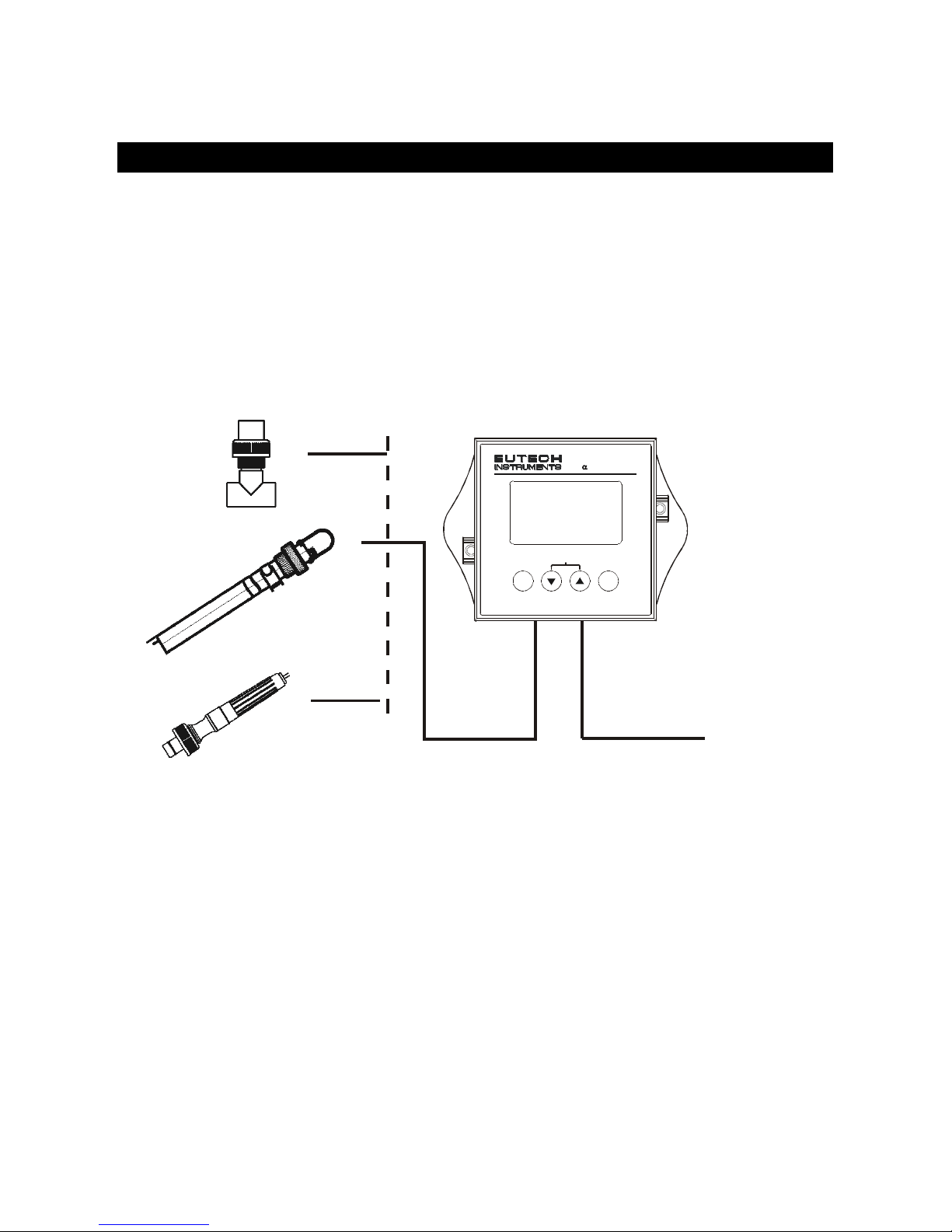
2.2 Measurement System
A typical measurement system consists of:
• A pH process monitor
• A pH sensor with integrated or separate Pt100/Pt1000 tem perature
sensor
• An appropriate measurement cable
• An immersion, flow or process assembly
Power Adap tor
(+9 V DC)
Measurement Cable
Housing and
Sensors
A
lpha pH 550 Monitor
ENT
ESC
pH Monitor
lpha pH550
CAL
- 5 -
2.3 Connecting Peripherals
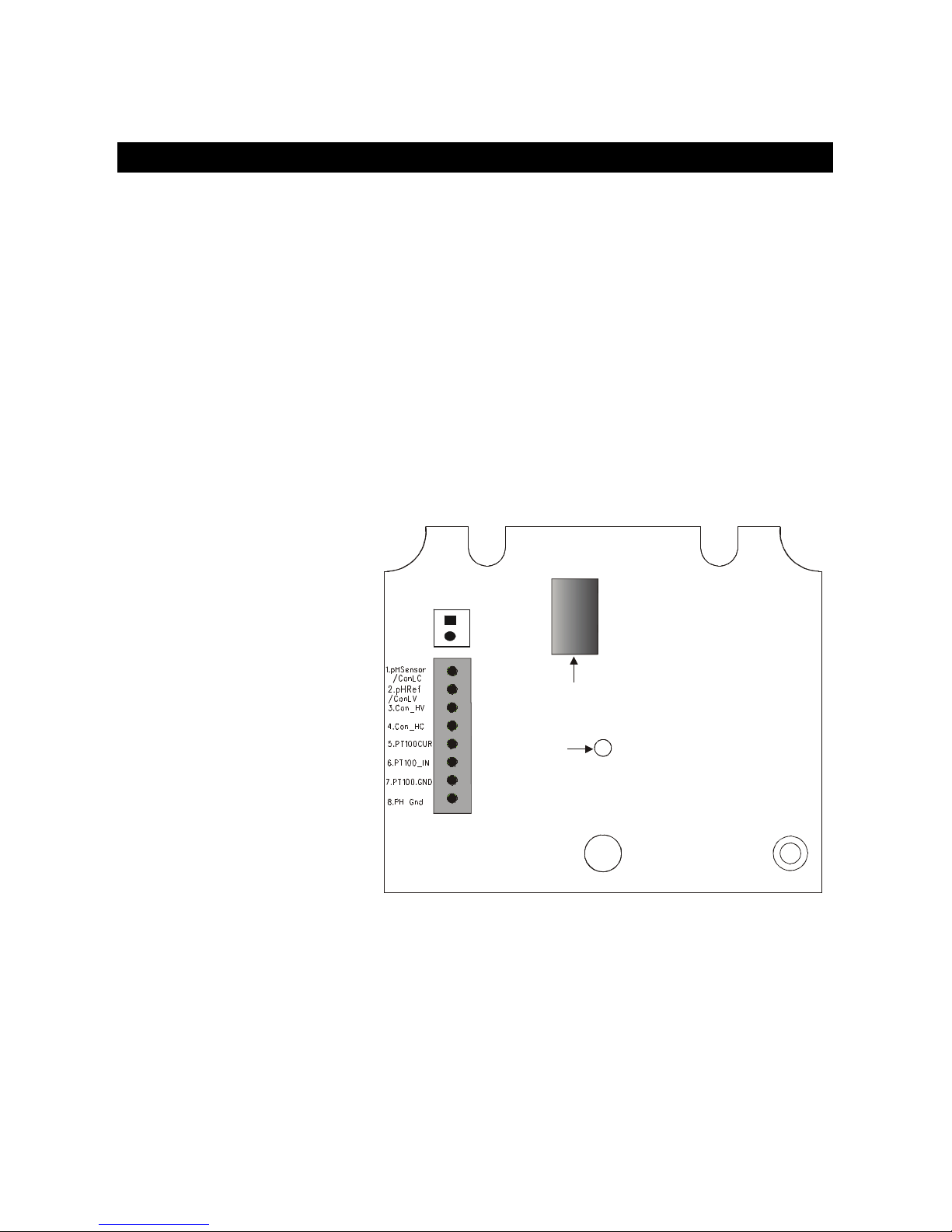
2.3.1 Connection Terminals
Remove Back Cover:
Remove the screws from the four corners at the back of the pH Monitor. Remove
the back cover. The connectors are exposed on the back PCBA as shown in the
Figure 1 below.
Connectors:
• J11 – 24V DC power
• J8 – 9V DC power
J10 - pH electrode & Temperature probe connections (wiring has to be done in
the detachable connector
Figure 1: Outer Side of Back PCBA
24V DC
J10
J8
9V DC Power
Screw
1)+v
J11 Connections
1. +ve
2. Gnd
J10 Connections
1. pH Sense
2. pH Reference
3. No Connection
4. No Connection
5. Pt 100 Compensate
6. Pt 100 Sense
7. Pt 100 GND
8. Potential Matching Pin

- 6 -
2.3.2 Switching Between PT100 & PT1000 Temperature Sensors
The Monitor supports both Pt100 & Pt1000 (2-wire or 3-wire) temperature sensors.
The default factory setting is Pt100. If you need to use Pt1000 temperature sensor,
you have to change the jumper setting (J7) as described below.
Remove Back Cover:
Remove screws from the four corners at the back of the pH Controller. Remove the
back cover.
Remove Back PCBA:
Remove the screw located center of the back PCBA (Figure 1). Detach the back
PCBA from the Controller. Turn over the back PCBA. Locate J7 jumper on the inner
side of the back PCBA as shown in
Figure
2 below.
Figure 2: Inner Side of Back PCBA
Set Jumper J7:
Set the J7 jumper to required sensor (Pt100 or Pt1000) type
- 7 -
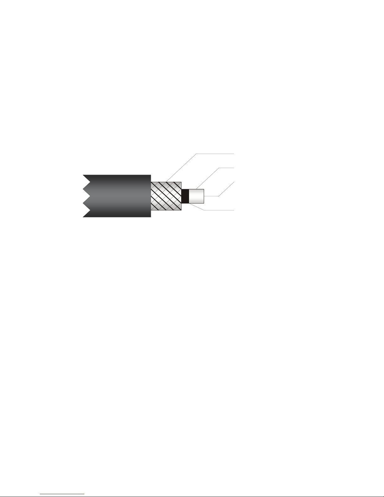
2.3.3 Connecting pH/ORP Electrode
1. If the pH/ORP electrode has a BNC connector, remove the BNC
connector from the cable.
NOTE: Oakton Instruments offers an optional ‘BNC to Spade Lug
adapter’ (Order code: 05994-90) that can be used with pH/ORP
electrode without removing the BNC connector.
2. Strip the insulation of the cable so that the bare wires are exposed
enough for connection as shown in Figure 3.
Figure 3 : pH/ORP Electrode Cable
NOTE: Make sure to strip inner black layer (screen) to expose the
clear sheath.
3. Connect pH sensing wire to Pin 1 of J10 connector
4. Connect pH reference wire to Pin 2 of J10 connector
Insulation
pH Reference Wire
Clear sheath
pH Sensing Wire
Screen

- 8 -
2.3.4 Connecting Temperature Probe
For Automatic Temperature Compensated (ATC) pH readings, a 100Ω Pt RTD
temperature probe (2-wire or 3-wire) can be connected to the Controller.
3-Wire Probe:
1. Connect PT100 compensate wire to Pin 5 of J10 connector
2. Connect PT100 sense wire to Pin 6 of J10 connector
3. Connect PT100 GND wire to Pin 7 of J10 connector
2-Wire Probe:
1. Short Pin 5 & 6 of J10 connector using a small piece of wire
2. Connect PT100 sense wire to Pin 6 of J10 connector
3. Connect PT100 GND wire to Pin 7 of J10 connector
2.3.5 Connect Potential Matching Pin (PMP)
If using an electrode with a PMP, connect the additional wire (PMP) from the pH
electrode to Pin 8 of J10 connector. This liquid electrical reference wire is only used
when the pH Controller is configured to ‘Symmetrical mode of operation’. Refer
section 5.5 for details on symmetrical mode of operation.
- 9 -
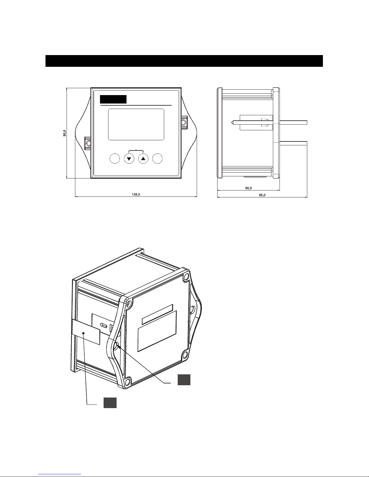
2.4 Installation
2.4.1 Mechanical Dimensions
2.4.2 Wall Mount
ENT
ESC
PH/ORP RF Transmitter
Alpha pH 60 0
CAL
11
Pierce through holes at both sides
2
Cover the catch slots at both sides
with overlays
Alpha pH 550
pH Monitor
- 10 -
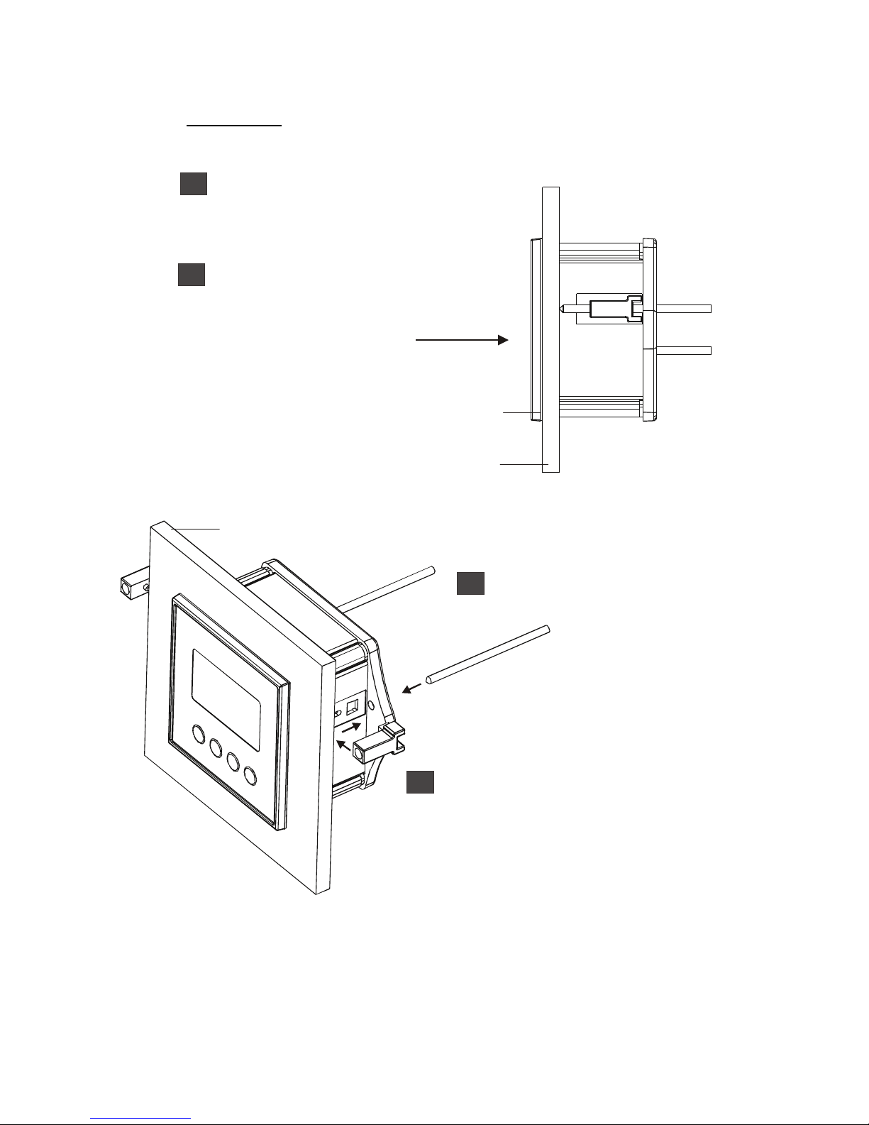
2.4.3 Panel Mount
Panel
Gasket
Prepare panel cut-out o
f
92.0 mm X 92.0 mm
Remove back cover o
f
pH Monitor and slide it
through panel cut-out
A
ttach catch to both sides
of pH Mete
r
Insert threaded rods through catch
until pH Meter is held against panel
2
3
4
1
1
Panel
 Loading...