

EUTECH INSTRUMENTS ALPHA PH 1000 PHORP CONTROLLERTRANSMITTER, alpha-pH1000 Instruction Manual
Tech n o l o
gyM
adeEas
y..
.
Instruction Manual
alpha-pH1000
pH and ORP Controller/Transmitter
68X216801 rev 1.1
07/02

Instruction Manual alpha-pH 1000
Preface
This manual serves to explain the use of the αlpha-pH1000 series pH/ORP controller/transmitter. The
manual functions in two ways, firstly as a step by step guide to help the user operate the instrument.
Secondly, it serves as a handy reference guide. This instruction manual is written to cover as many
anticipated applications of the αlpha-pH1000 pH/ORP controller/transmitter. If you have doubts in the use
of the instrument, please do not hesitate to contact the nearest Eutech Instruments’ Authorised Distributor.
The information presented in this manual is subject to change without notice as improvements are made,
and does not represent a commitment on part of Eutech Instruments Pte Ltd.
Eutech Instruments cannot accept any responsibility for damage or malfunction of the unit due to improper
use of the instrument.
Copyright 1997 Eutech Instruments Pte Ltd. Revised in July 2002.
All rights reserved.

Instruction Manual alpha-pH 1000
Safety Information
The Eutech Controller/ Transmitter shall be installed and operated only in the manner specified in the
Instruction manual. Only skilled, trained or authorized person should carry out installation, setup and operation
of the instrument.
Before powering up the unit, make sure that power source it is connected to, is as specified in the top label.
Failure to do so may result in a permanent damage to the unit.
The unit has live and exposed parts inside. If it has to be opened, make sure that the power to the unit is off
and disconnected.
The unit is Fuse protected. In the event the fuse has to be replaced, use only those as specified in the manual.

Instruction Manual alpha-pH 1000
TABLE OF CONTENTS
1 INTRODUCTION 5
1.1 Description of Unit 5
1.2 Applications 5
2 ASSEMBLY AND INSTALLATION 6
2.1 Measurement and Control System 6
2.2 Unit Dimensions 6
3 ELECTRICAL CONNECTION 7
3.1 Connection Diagram 7
3.2 Back Panel 9
4 OVERVIEW 10
4.1 Keypad and Display 10
4.2 Function Groups 11
4.3 Control Concept 12
5 MEASUREMENT 13
5.1 Display in Measurement mode 13
5.2 Security Codes 13
6 CALIBRATION MODE 15
6.1 pH Calibration 15
6.2 ORP – mV Calibration 16
6.3 ORP -% Calibration 17
7 ADVANCED SET-UP MODE 18
7.1 Electrode Offset (OFS) sub-function 18
7.2 Setting temperature (Set oC) sub-function 18
7.3 Control Relay A/Control Relay B (SP1/SP2) sub-function 20
7.4 Controller (Cntr) sub-function 22
7.5 Current Output (rng) sub-function 24
7.6 Configuration (ConF) sub-function 25
7.7 Calibration (CAL) sub-function 28
8 AUTO/MANUAL MODE 29
8.1 Auto mode (mode after switch-on) 29
8.2 Manual mode 29
9 TECHNICAL SPECIFICATIONS 30
10 ACCESSORIES 32
11 GENERAL INFORMATION 33
11.1 Warranty 33
11.2 Packaging 33
11.3 Return of Goods 33
11.4 Guidelines for Returning Unit for Repair 33
12 APPENDICES 34
12.1 Appendix 1 34
12.2 Appendix 2 35
12.3 Appendix 3 36
12.4 Appendix 4 37

Instruction Manual alpha-pH 1000
5
1 INTRODUCTION
1.1 Description of Unit
Thank you for purchasing Eutech’s ¼ DIN alpha-1000 series pH/ORP process controllers. This unit is used
for measuring either pH or ORP parameter one at a time, and the operational mode is switchable from the
menu. You can use this unit to measure pH or ORP with proportional or limit control. This controller has
many user-friendly and safety features which include:
• Menu-driven program that simplifies set-up
• Built-in memory backup to ensure that calibration and other information are not erased if power
supply fails
• Push-button two-point calibration and electrode offset adjustment from the keypad
• Automatic temperature compensation (ATC)
• Manual temperature compensation setting without the ATC probe, with independent setting for
calibration and process temperature
• 0 to 2000 second time delay adjustment on all relays – minimise false alarms
• Separately adjustable high and low set point hysteresis (dead bands) prevent chattering of relays
around the set points
• Asymmetrical/symmetrical input for pH/ORP mode of operation
• Three control modes: limit, proportional pulse length or proportional pulse frequency
• Large dual display LCD for easy reading with clear multiple annunciators, alarm status, operational
and error messages
• Two switching contacts as set-point triggering relays and an alarm output relay
• A third relay that can be set up to perform either Alarm or Wash function
• When set to work as Alarm relay, alerts you to set points exceeded for a set-point limits for certain
time and if the Pt100/Pt1000 wires are broken or disconnected during the ATC function
• Programmable duration and frequency in the Wash mode
• Hold function freezes output current (0/4...20mA) and releases control relays
• LED indicators signal control activities to monitor controller status from a distance
• Protection against electromagnetic interference - galvanically isolated 0/4..20mA output provides
safety for data logging and control purposes
•
Choice of 7 buffers from USA or NIST standards
1.2 Applications
Use this controller in panel mounted enclosures for applications such as water treatment and monitoring,
galvanic-decontamination, chemical processing food processing, clean or waste water control and
neutralisation process.
Instruction Manual alpha-pH 1000
6
2 ASSEMBLY AND INSTALLATION
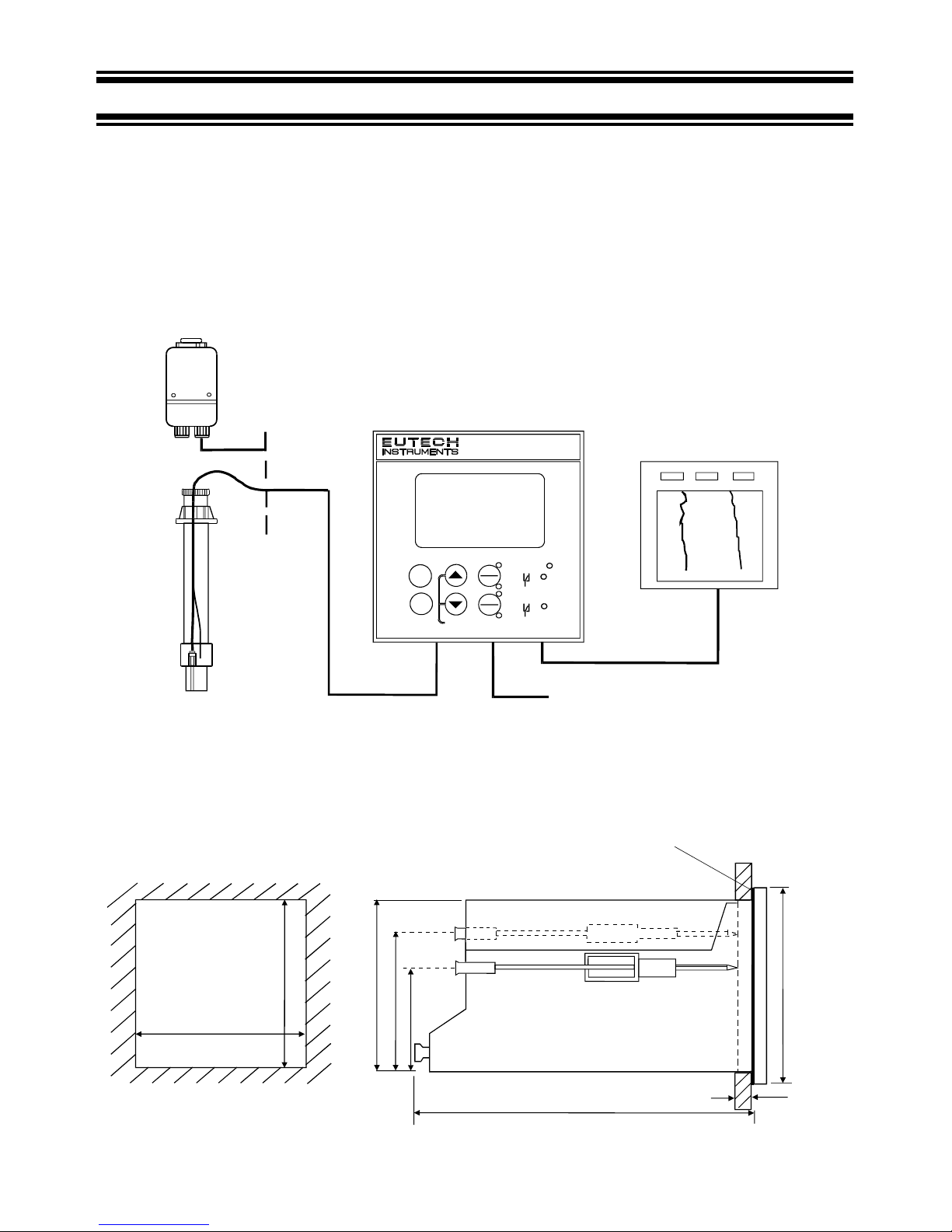
2.1 Measurement and Control System
A typical measurement system consists of:
• a pH/ORP process controller
• a pH/ORP combination electrode with integrated or separate temperature sensor Pt 100/1000,
• an immersion, flow or process assembly with or without a potential matching pin (PMP)
• a final control element such as pump or valve
• a recorder and
• an appropriate pH or ORP measurement cable.
2.2 Unit Dimensions
The field-tested control panel housing is 96 x 96 mm; with protection class IP 54 (front).
max. 175
max. 45
Mounting Cut-Out
Flat
G
asket
(
1mm)
(To be Inserted By Customer)
Note: The Taped Corners Have to Be On Top
92
32
56
96
92 + 0.5
92 + 0.5
Power Mains
(220/110 VAC)
Flow Assembly
Measurement Cable
Process Assembly
with El
e
ctrode
Chart Recorde
r
pH Controller
ALARM
REL A
REL B
ESC
CAL
ENTER
REL A
AUTO
REL B
MANU
7.02
25.0
pH
o
C
ATC
MEAS
alpha-pH1000
Instruction Manual alpha-pH 1000
7
3 ELECTRICAL CONNECTION
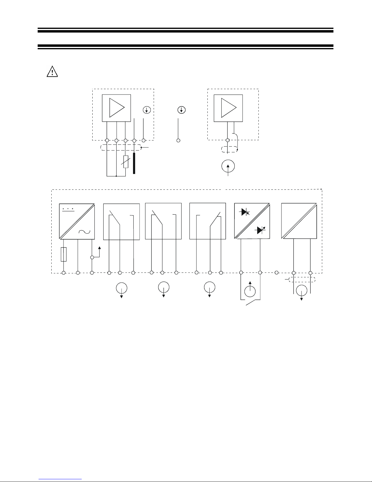
3.1 Connection Diagram
Caution: Ensure electrical mains is disconnected before proceeding.
Signal OutputHold Input
Relay B
Relay A
Power Mains
pH
mA
Alarm/Wash
-
+
PE/S
PEAC: NL
1
2
5
4
36
78 9
10
11
12 13
14
151715
16
* ) indicated contact positions are for currentless conditions
Pt 100
Potential Matching Pin (PMP)
Signal Input pH
/
ORP
S/
V
PE/S
pH
18 19 20 21 22
S/S/
BNC
Instruction Manual alpha-pH 1000
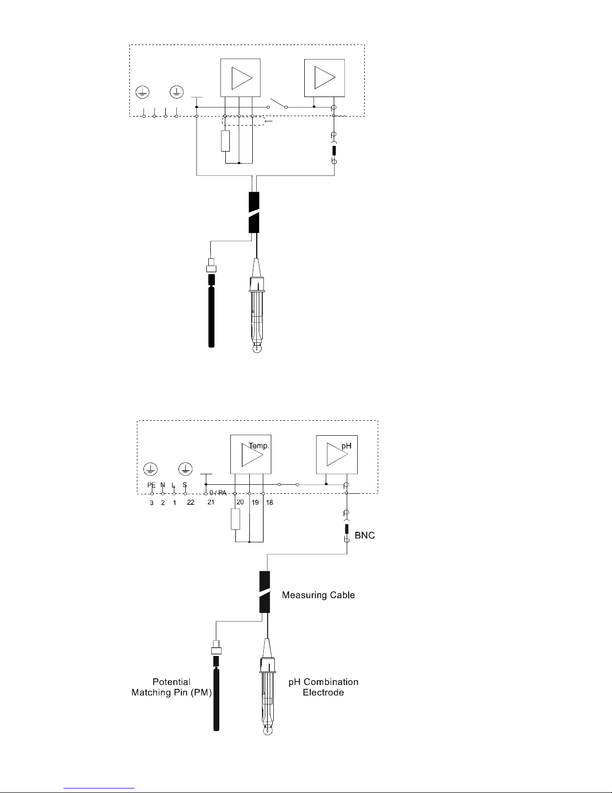
8
Symmetrical high-impedance
connections
Asymmetrical connections
Measuring Cable
pH Combination
Electrode
Te mp .
pH
BNC
0/PA
PE
N
L
S
22
21
1
2
3
20
19 18
Potential
Matching Pin (PM)
S
Instruction Manual alpha-pH 1000
9
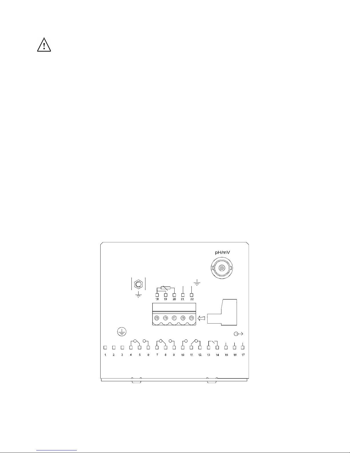
3.2 Back Panel
Caution: Ensure electrical mains is disconnected before proceeding.
The back panel consists of two connectors. The first connector is the 17-way PCB edge connector and the
other is the 5-way connector.
Connection for the 17-way screw terminals (from left to right):
1. AC mains live wire 10. Alarm/Wash relay working position (NO)
2. AC mains neutral wire 11. Alarm/Wash relay common
3. AC mains protective earth wire 12. Alarm/Wash relay resting position (NC)
4. Low set relay resting position (NC) 13. Hold function switch terminal 1
5. Low set relay common 14. Hold function switch terminal 2
6. Low set relay working position (NO) 15. No connection
7. High set relay resting position (NC) 16. 0/4 - 20 mA for -ve connection
8. High set relay common 17. 0/4 - 20 mA for +ve connection
9. High set relay working position (NO)
Connections for the 5-way screw terminals:
18. Pt100/Pt1000 lead 1 terminal
19. Pt100/Pt1000 sense lead terminal
20. Pt100/Pt1000 lead 2 terminal
Note: If using a two-wire RTD, short terminal 19 to terminal 18.
Pt 100/Pt 1000 is selectable via an internal jumper. Factory default is Pt100. See Appendix 1 for
directions on switching the RTD type.
21. pH/ORP (potential matching pin)
21. pH/ORP (shield)
0V
/
Pt100
/
RELAY A
L
N
PE
100mA
(F)
FUSE 250VAC
HOLD
A
LARM / WASHRELAY B
Pt1000
PAL
S/
NC
-
+
IMPORTANT: The Alarm relay functions as an “Active Low” device i.e. it switches OFF under Alarm
condition. Therefore the Alarm display device should be connected to the ‘NC’ contacts of the relay (11
and 12). In the Wash mode, the relay works on a positive mode. Therefore, the Wash device should be
connected to the contacts 10 and 11.
Instruction Manual alpha-pH 1000
10
4 OVERVIEW
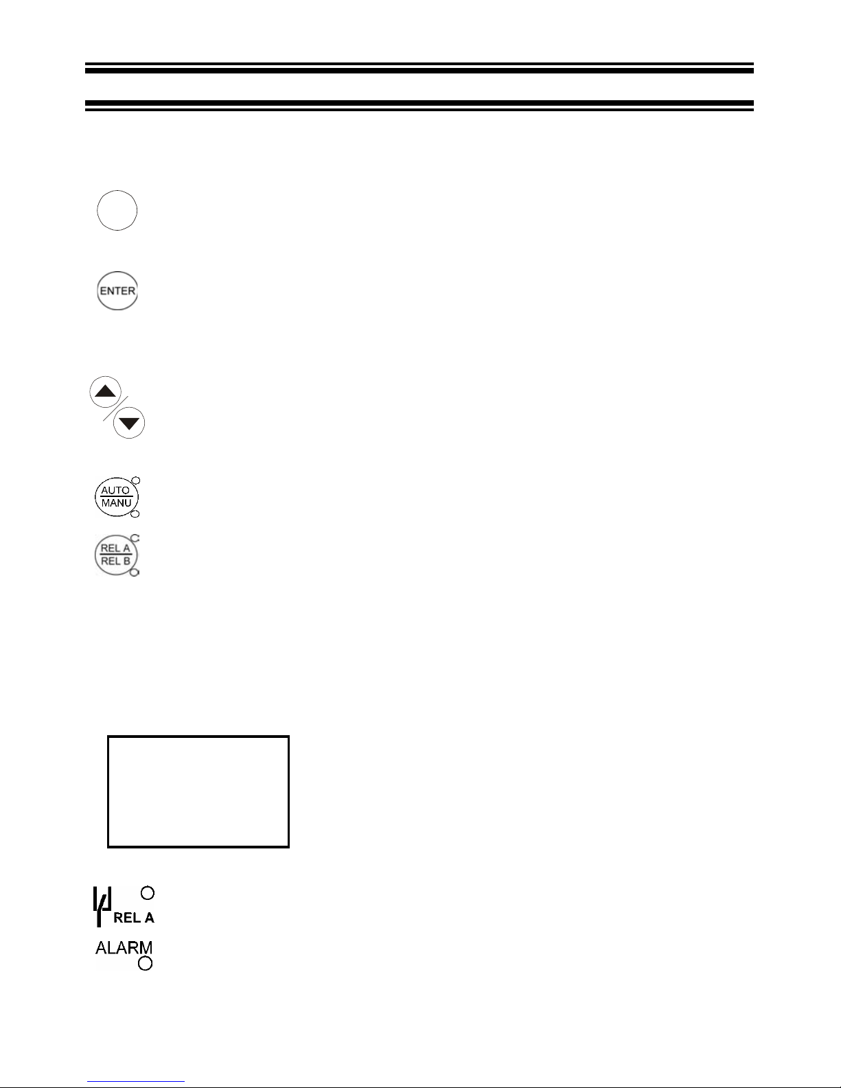
4.1 Keypad and Display
4.1.1 Keypad
CAL
•
Perform rapid 2-point calibration
•
Allows entry to Set up mode
• Select individual functions within the function group of Set up mode
• Store input data in the Set up mode
• Start calibration in the calibration mode
•
Select various function groups in the Set up mode.
• Set parameters and numerical values in sub functions of Set up mode
If pressed continuously, the setting speed increases
• Control the relays in the MANUAL function
• Return to the Measurement mode when both keys are pressed together
•
Switch between AUTO and MANUAL relay operation using a code
•
Display limit set-point values for the switch contacts in AUTO relay operation mode
• Switch between RELAY A and RELAY B in MANUAL relay operation mode
4.1.2 Display
The LCD display features two numerical displays that show status messages and measured values for easy,
quick reference. The display provides short-text information for setting parameters and configuration.
7.00
25.0
ATC
SETUP
HOLD
CAL
MEAS
CON
READY
pH
ERR
o
C
•
MEAS: Measurement mode
• SETUP: Set-up mode of function groups
• CAL: Calibration mode of pH/ORP and temperature
• READY: Comes on after a successful calibration
• HOLD: Relay position and current output are frozen
• ATC: Comes on in the ATC mode. Disappears in the
Manual temperature Compensation mode.
“ATC” flashes if the temperature probe is faulty in its ATC
mode
• ERR: Error or alarm indicator
•
Display for RELAY A/B. Green LED indicates measured value within limit while
RED LED indicates measured value outside limit.
•
Alarm display if limit value overshoot or the ATC probe fails; with ERR annunciator
appears on the display. Wash display if cleaning cycle is on.

Instruction Manual alpha-pH 1000
11
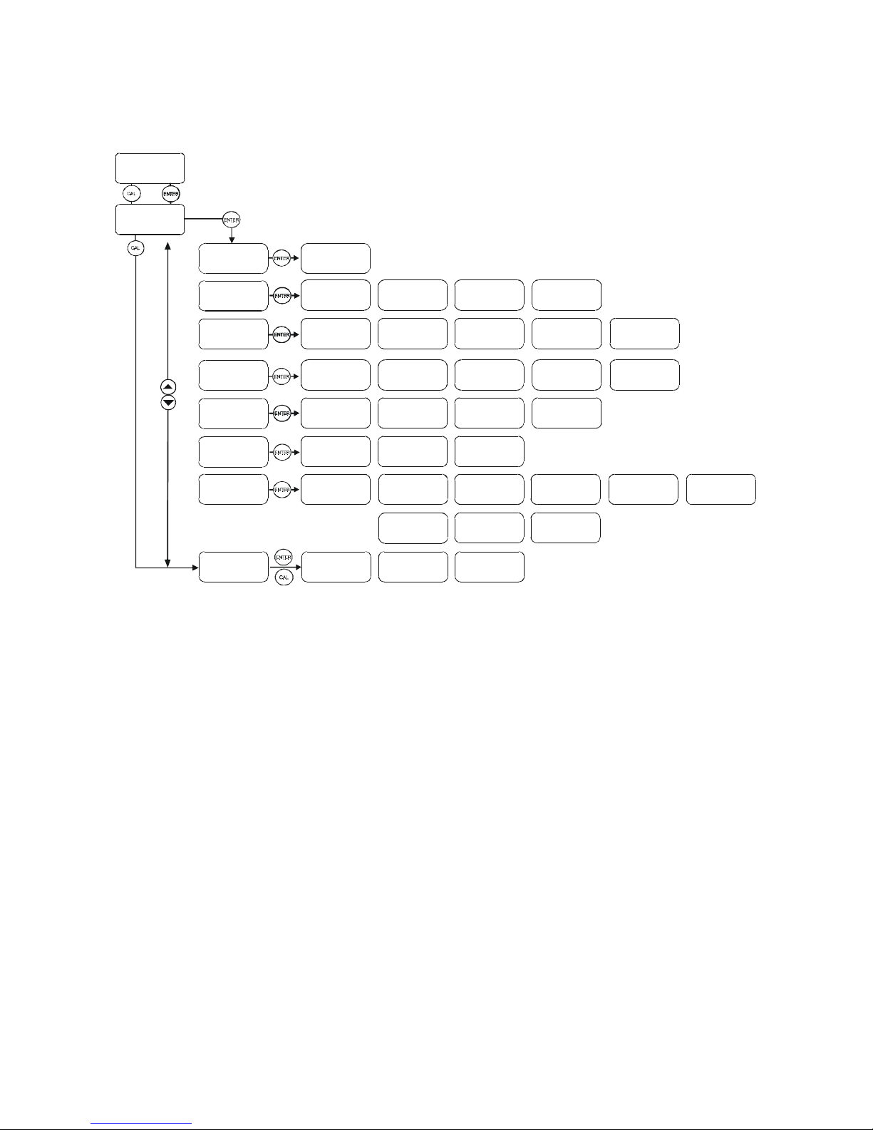
4.2 Function Groups
The main function and sub-function groups are organised in a matrix format for configuration and selection of
parameters. The main function groups are:
1) Offset adjustment (OFS)
2) Temperature Measurement / compensation settings (Set
o
C)
3) Control relay 1 configuration (SP1)
4) Control relay 2 configuration (SP2)
5) Control type (Cntr)
6) Current output (rng)
7) Configuration (ConF)
8) Calibration (CAL pH)
The set-up parameters can be viewed or changed by entering a security code. See Section 5.2 for security
code information.
4.2.1 How to view operating parameters without access to change them:
a) Press the ENTER key. The display will prompt the user to enter a
security code (S.Cd). Leave the security code at “000” (do not enter a
security code).
b) Press ENTER key again. This allows you only to view (not change) any
sub-functions’ settings.
c) Press the ▲ or ▼ key to scroll through the sub-functions.
d) Press the ENTER key at a particular sub-function to view in detail.
e) Press the ENTER key to return to the sub-function menu.
f) Press the ▲ and ▼ keys simultaneously (as an Escape key) at any time to return to the Measurement
mode.
Note: To simplify operations, the controller will not display parameters that are not relevant to a particular subfunction. For example: If the user set the controller for Limit control, it will not display pulse length/frequency
settings.
000
S.Cd
SETUP
HOLD
OFS
SETUP
HOLD
SEt
o
C
SETUP
HOLD
SP1
SETUP
HOLD
SP2
SETUP
HOLD
ConF
SETUP
HOLD
rng
SETUP
HOLD
Cntr
SETUP
HOLD
CAL
pH
SETUP
HOLD
Instruction Manual alpha-pH 1000
12
4.3 Control Concept
The main function and sub-function groups are organised in a matrix format as shown below. These functions
can be accessed via the front keypad for configuration and selection of parameters.
CALIBRATION
MEASU RE
CODE
OFFSET
SET C
o
SET- POIN T 1
SET- POIN T 2
CONTROLLER
MEASUREMENT
RANGE
CONFIGURATION
Set Offset
Switc h On/Off ATC
Set value 1
Set value 2
Controll er type
Current output
0..20 / 4 ..20 mA
pH / ORP Symm.
/ Asym metr ical
CLn
ALr
Proces s temp .
(MTC)
Calibrate 1st value
MIN / MAX Func tion
MIN / MAX Func tion
N.O/N.C. Contact
pH / ORP
at 0/4 m A
Alarm delay
00
Intv
Calibrat e 2nd value
Calib. temp .
(MTC)
Hystere sis 1
Hystere sis 2
Prop ortional
range X P
pH / ORP
at 20 mA
Alarm c ontact
cont. /wiper contact
1000
Dur
Display zero point
and slo pe
Calibrat e Pt100
Pick-up delay
contact 1
Pick-up delay
contact 2
Cycle time bz w.
max. frequency
Elect rode t ype
Glass/Antimony
Dropou t delay
conta ct 1
Dropou t delay
conta ct 2
Reset to factory
defa ult settings
The controller offers two levels of password protection: (1) for direct access to calibration function and (2) for
setting or editing specific controller parameters or functions in the SETUP mode to suit individual requirements.
Note: The passwords are not user-defined and have been set by factory. It is very important to keep these
passwords strictly confidential to avoid unauthorised tampering of the system at all times.
Note: If the user reads parameters only, the controller automatically reverts to Measurement mode if no key is
pressed for 30 seconds.
 Loading...