

Page 1

Alpha COND 1000
Controller/Transmitter
uS/cm / mS/cm / ºC
Page 2

ROSS and the COIL trade dress are trademarks of Thermo Fisher Scientific Inc.
U.S. patent 6,793,787.
AQUAfast, Cahn, ionplus, KNIpHE, No Cal, ORION, perpHect, PerpHecT,
PerpHecTion, pHISA, pHuture, Pure Water, Sage, Sensing the Future, SensorLink,
ROSS, ROSS Ultra, Sure-Flow, Titrator PLUS and TURBO2 are registered
trademarks of Thermo Fisher.
1-888-pHAX-ION, A+, All in One, Aplus, AQUAsnap, AssuredAccuracy, AUTO -BAR,
AUTO-CAL, AUTO DISPENSER, Auto-ID, AUTO-LOG, AUTO-READ, AUTO-STIR,
Auto-Test, BOD AutoEZ, Cable-Free, CERTI-CAL, CISA, DataCOLLECT,
DataPLUS, digital LogR, DirectCal, DuraProbe, Environmental Product Authority,
Extra Easy/Extra Value, FAST QC, GAP, GLPcal, GLPcheck, GLPdoc, ISEasy,
KAP, LabConnect, LogR, Low Maintenance Triode, Minimum Stir Requirement,
MSR, NISS, One-Touch, One-Touch Calibration, One-Touch Measurement,
Optimum Results, Orion Star, Pentrode, pHuture MMS, pHuture Pentrode, pHuture
Quatrode, pHuture Triode, Quatrode, QuiKcheK, rf link, ROSS Resolution, SAOB,
SMART AVERAGING, Smart CheK, SMART STABILITY, Stacked, Star Navigator
21, Stat Face, The Enhanced Lab, ThermaSense, Triode, TRIUMpH, Unbreakable
pH, Universal Access are trademarks of Thermo Fisher.
Guaranteed Success and The Technical Edge are service marks of Thermo Fisher.
PerpHecT meters are protected by U.S. patent 6,168,707. PerpHecT ROSS
electrodes are protected by U.S. patent 6,168,707. ORION Series A meters and
900A printer are protected by U.S. patents 5,198,093, D334,208 and
D346,753.ionplus electrodes and Optimum Results solutions are protected by U.S.
patent 5,830,338.ROSS Ultra electrodes are protected by U.S. patent
6,793,787.ORP standard is protected by U.S. patent 6,350,367. No Cal electrodes
are protected by U.S. patent 7,276,142.© 2009 Thermo Fisher Scientific Inc. All
rights reserved. All trademarks are the property of Thermo Fisher Scientific Inc. and
its subsidiaries.The specifications, descriptions, drawings, ordering information and
part numbers within this document are subject to change without notice.This
publication supersedes all previous publications on this subject.
Page 3

Preface
This manual serves to explain the use of the Alpha COND 1000 process
controller/transmitter. The manual functions in two ways, firstly as a step by step
guide to help the user operate the instrument. Secondly, it serves as a hand y
reference guide. This instruction manual is written to cover as many anticipated
applications of the Alpha COND 1000 process controller/transmitter. If you have
doubts in the use of the instrument, please do not hesitate to contact the nearest
Authorized Distributor.
Thermo Scientific will not accept any responsibility for damage or malfunction of
the unit due to improper use of the instrument.
The information presented in this manual is subject to change without notice as
improvements are made, and does not represent a commitment on part of
Thermo Scientific.
Copyright ©2009
All rights reserved.
Page 4

Page 5

Safety Information
The Controller/ Transmitter shall be installed and operated only in the manner
specified in the Instruction manual. Only skilled, trained or authorized person shoul d
carry out installation, setup and operation of the instrument.
Before powering up the unit, make sure that power source it is connected to, is as
specified in the top label. Failure to do so may result in a permanent damage to the
unit.
The unit has live and exposed parts inside. If it has to be opened, make sure that
the power to the unit is off and disconnected.
The unit is Fuse protected. In the event the fuse has to be replaced, use only those
as specified in the manual.
Page 6

TABLE OF CONTENTS
INTRODUCTION................................................................................1
1
1.1 Description of Unit.....................................................................................1
1.2 Applications ..............................................................................................1
2 ASSEMBLY AND INSTALLATION ...................................................2
2.1 Measurement and Control System............................................................2
2.2 Unit Dimensions........................................ Error! Bookmark not defined.
3 ELECTRICAL CONNECTION............................................................3
3.1 Connection Diagram.................................................................................3
3.2 Back Panel................................................................................................4
4 OVERVIEW ........................................................................................5
4.1 Keypad and Display..................................................................................5
4.1.1 Keypad ................................................................................5
4.1.2 Display.................................................................................5
4.2 Function Groups .......................................................................................6
4.2.1 How to view operating parameters without access to
change them:......................................................................................6
4.3 Control Concept........................................................................................7
5 MEASUREMENT ...............................................................................8
5.1 Display in Measurement mode..................................................................8
5.1.1 Check electrode performance.............................................8
5.1.2 Checking set points.............................................................8
5.2 Security Codes..........................................................................................9
5.2.1 How to enter and change parameters in Calibration mode.9
5.2.2 How to enter and change parameters in Advanced Setup
mode 9
6 CALIBRATION MODE.....................................................................11
6.1 Conductivity Calibration..........................................................................11
7 ADVANCED SET-UP MODE...........................................................13
7.1 Temperature Coefficient sub-function.....................................................13
7.1.1 Selecting Pure-water or Linear Temperature Coefficient..13
7.2 Temperature Calibration (ATC mode only).............................................14
7.2.1 Setting Manual Temperature Compensation ....................14
7.3 Control Relay A/Control Relay B (SP1/SP2) sub-function ......................15
7.3.1 Entering the Set point 1 (or Set point 2) sub-function.......15
7.3.2 Selecting the set point values............................................15
7.3.3 Choosing High or Low set points.......................................16
7.3.4 Selecting a hysteresis (dead band) value .........................16
7.3.5 Setting an on-delay time lag..............................................17
7.3.6 Setting an off-delay time lag..............................................17
7.4 Controller (Cntr) sub-function..................................................................18
Page 7

7.4.1
Entering the Controller sub-function..................................18
7.4.2 Choosing the controller type (limit or proportional) ...........19
7.4.3 Choosing Break/Make Contact Relay Type......................19
7.4.4 Selecting Proportional Range Value, Xp...........................20
7.4.5 Maximum Pulse Length (tPL) or Maximum Frequency (FPF)
20
7.5 Measurement Range sub-function..........................................................21
7.5.1 Selecting the Measuring Range sub-function ...................21
7.6 Current Output (rng) sub-function...........................................................22
7.6.1 Entering current output sub-function.................................22
7.6.2 Choosing the output type ..................................................22
7.6.3 Selecting Conductivity value at 0(4)mA.............................22
7.6.4 Selecting Conductivity value at 20mA...............................23
7.7 Configuration (ConF) sub-function..........................................................23
7.7.1 Entering the Configuration sub-function............................23
7.7.2 Selecting Filter Function and the Alarm or Wash Function
23
7.7.3 Selecting the alarm time lag..............................................24
7.7.4 Selecting steady or pulse contact for the alarm relay .......24
7.7.5 Wash contact (if the relay 3 is set to Wash)......................25
7.7.6 Input Line Resistance Adjust.............................................25
7.7.7 Reverting to factory default settings..................................25
7.8 Calibration (CAL) sub-function............................................................26
7.8.1 Entering Calibration mode from Advanced Set-up mode..26
8 AUTO/MANUAL MODE...................................................................27
8.1 Auto mode (mode after switch-on)..........................................................27
8.2 Manual mode..........................................................................................27
9 TECHNICAL SPECIFICATIONS .....................................................28
10 ACCESSORIES ...............................................................................29
11 GENERAL INFORMATION..............................................................29
11.1 Warranty .............................................................................................29
11.2 Packaging...........................................................................................29
11.3 Return of Goods..................................................................................29
11.4 Guidelines for Returning Unit for Repair .............................................30
12 APPENDICES ..................................................................................30
12.1 Appendix 1 – Jumper Positions...........................................................30
12.2 Appendix 2 – Measurement Ranges available in the Controller..........31
12.3 Appendix 3 – Conductivity at Related Temperature Coefficients (25 °C)
31
12.4 Appendix 4 – Conductivity of Various Aqueous Solutions at 25 C....33
12.5 Appendix 5 - Simple Explanation on the Function of Hysteresis.........34
12.6 Appendix 6 – General Instructions Concerning Controller Setting......35
Page 8

Page 9

1 INTRODUCTION
1.1 Description of Unit
Thank you for purchasing the ¼ DIN Alpha COND 1000 series Conductivity
process controllers. This unit is used for measuring the Conductivity of a
solution, either in micro-Siemens or milli-Siemens, one at a time, and the
operational mode is switchable from the menu. You can use this unit to measure
Conductivity with limit control. This controller has many user-friendly and safety
features which include:
• Menu-driven program that simplifies set-up
• Ten ranges of Conductivity measurements-software selectable (Appendix
2).
• Built-in memory backup to ensure that calibration data and other
information are not erased if power supply fails
• Automatic temperature compensation (ATC) with Pt100 or Pt 1000
• Manual temperature compensation with independent setting for
calibration and process temperature
• Temperature coefficient variable between 0.00 to 10.00 % per
pure water compensation curve stored in memory. Reference temperature
at 25oC.
• 0 to 1999 second time delay adjustment on all relays – minimise false
alarms
• Separately adjustable high and low set point hysteresis (dead bands)
prevents chattering of relays around the set points. Selectable Filter
function stabilises rapid measurement changes
• Four operating modes: limit, display monitor , proportional pulse length or
proportional pulse frequency control.
• Large dual display LCD for easy reading with clear multiple annunciators,
alarm status and operational message annunciators
• Two switching contacts as set-point triggering relays and an alarm
output relay
• Separate alarm relay alerts you when set points have exceeded the limits
and if the Pt100/Pt1000 wires are broken or disconnected during the ATC
function
• Hold function freezes output current (0/4...20mA) and releases control
relays
• LED indicators signal control activities to monitor controller status from a
distance
• Protection against electromagnetic interference - galvanically isolated
0/4 - 20mA output provides safety for data logging and control purposes
1.2 Applications
Use this controller in panel mounted enclosures for applications in water treatment
and demineralization, waste water treatment and neutralization processes.
o
C. Separate
1
Page 10
Operating Instructions Thermo Scientific Alpha COND 1000
A
G
)
2 ASSEMBLY AND INSTALLATION
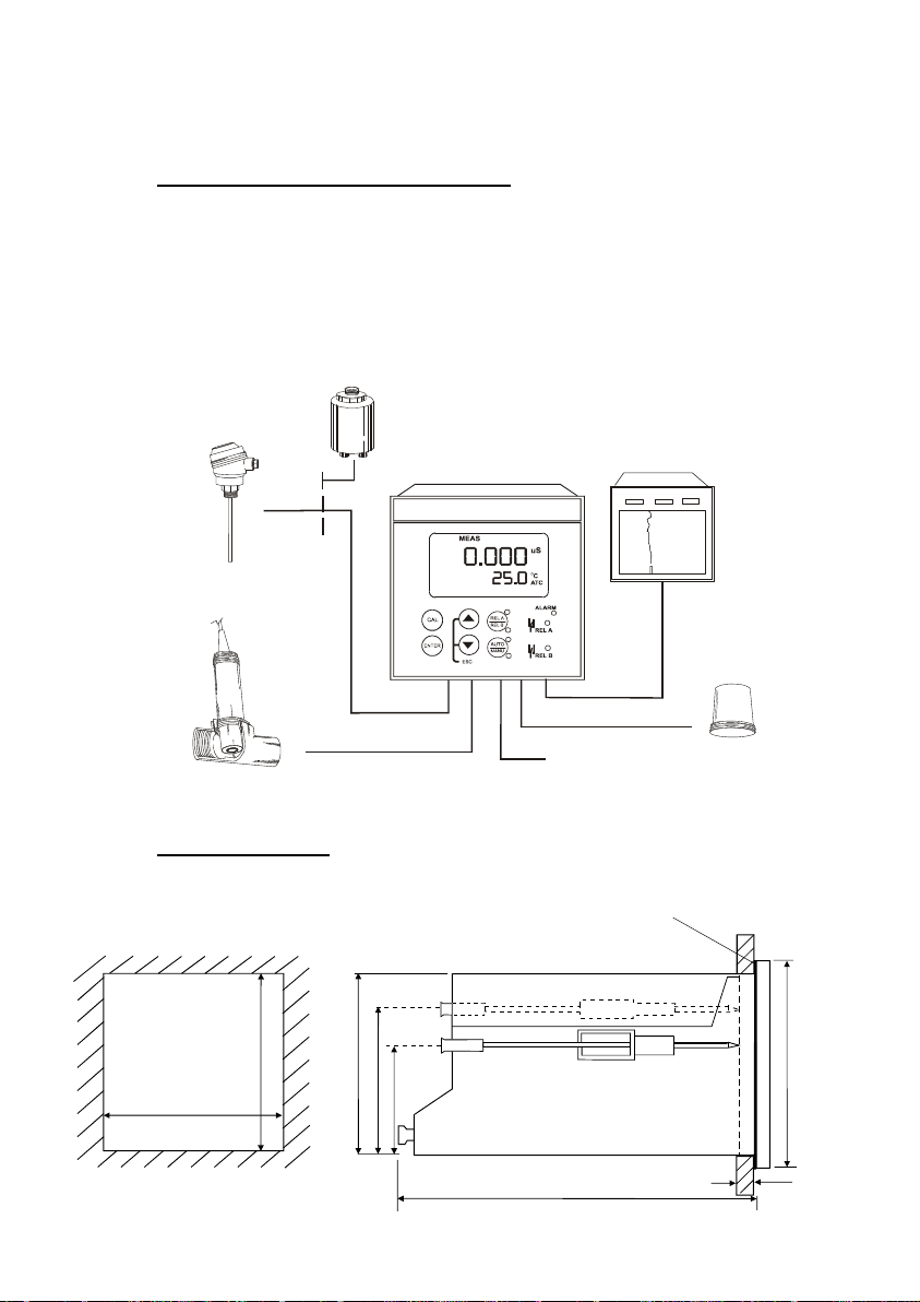
2.1 Measurement and Control System
A typical measurement system consists of:
• a Alpha COND 1000 process controller
• a suitable Conductivity electrode with the appropriate Cell constant and
integrated temperature sensor Pt 1000 or Pt 100,
• an immersion, flow or process assembly
• a final control element such as pump or valve and
• a chart recorder.
Flow Assembly
to Dosing Pumps
Chart Recorder
Power Mains
(220/110 VAC)
Alarm / Siren
System
Pt100/Pt1000
Temperature Sensor
Process Assembly
with Electrode
Alpha COND 1000
Alpha-CON1000 Controller
lpha-CON1000
2.2 Unit Dimensions
The field-tested control panel housing is 96 x 96 mm; with protection class IP 54
(front).
92 + 0.5
92 + 0.5
asket(1mm
Flat
(Tobe Inserted By Customer)
Note: The Taped Corners Have to Be On Top
92
56
32
96
Mounting Cut-Out
2
max. 175
max. 45
Page 11
Operating Instructions Thermo Scientific Alpha COND 1000
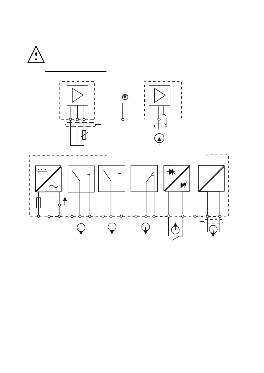
3 ELECTRICAL CONNECTION
ENSURE that the power cable is physically separated from the power
supply.
3.1 Connection Diagram
V
Cond.
S/
S/
Power Mains
2
1
18 19 20
PE/S
Pt 100
Relay 1
36
PEAC: NL
* ) indicated contact positions are for currentless or no error conditions
5
4
Relay 2
78 9
21 22
Signal Input Conductivity
Alarm
10
11
12 13
14
PE/S
Signal OutputHold Input
Cond.
-
151715 16
mA
+
3
Page 12
Operating Instructions Thermo Scientific Alpha COND 1000
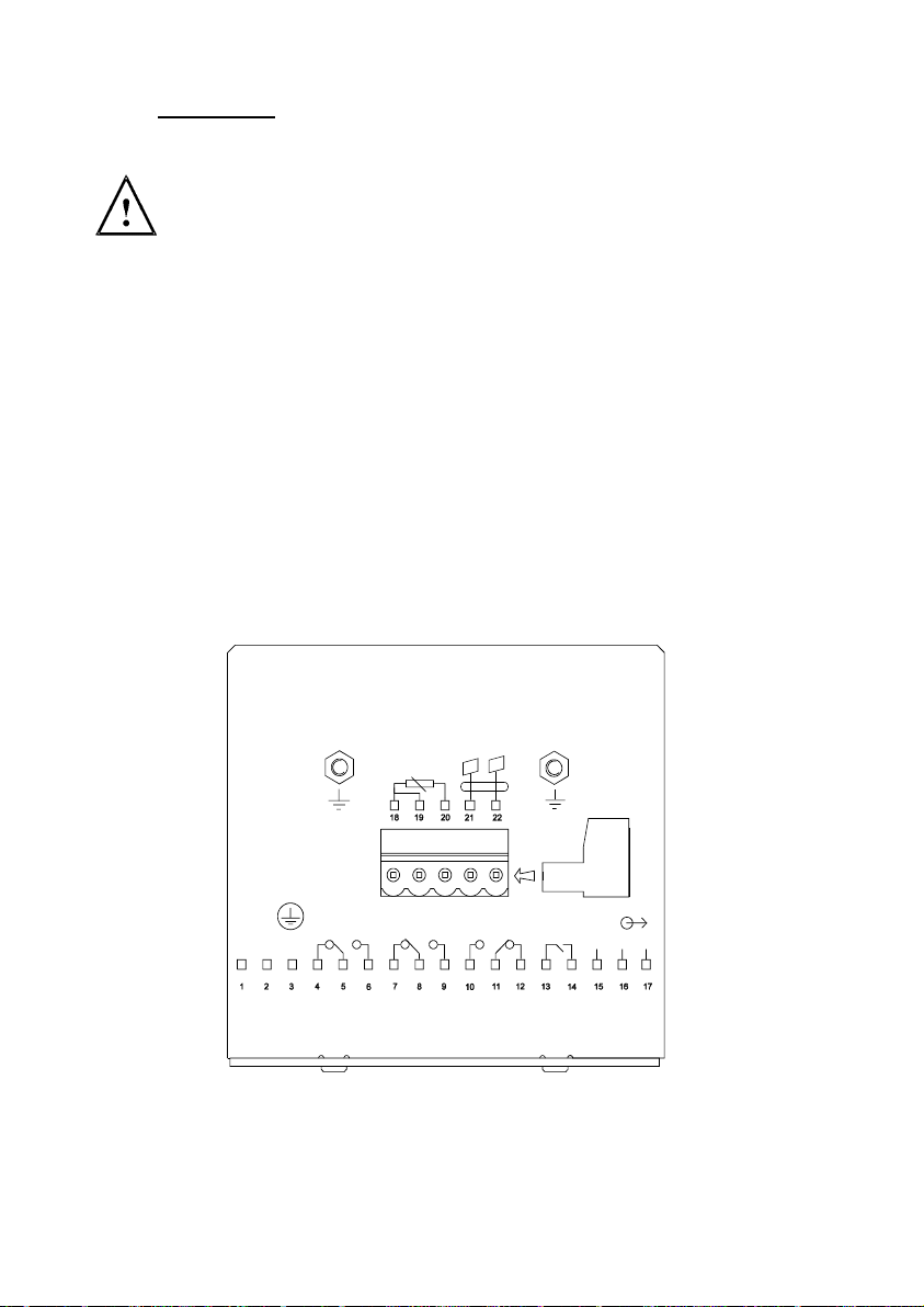
3.2 Back Panel
The back panel consists of two connectors. The first connector is the 17-way PCB
edge connector and the other is the 5-way connector.
ENSURE that the power cable is physically separated from the power
supply.
Connection for the 17-way screw terminals (from left to right):
1. AC mains live wire 10. Alarm relay resting position (NO)
2. AC mains neutral wire 11. Alarm relay common
3. AC mains protective earth wire 12. Alarm relay working position (NC)
4. Low set relay resting position (NC) 13. Hold function switch terminal 1
5. Low set relay common 14. Hold function switch terminal 2
6. Low set relay working position (NO) 15. No connection
7. High set relay resting position (NC) 16. 0/4 - 20 mA for -ve connection
8. High set relay common 17. 0/4 - 20 mA for +ve connection
9. High set relay working position (NO)
Connections for the 5-way screw terminals:
18. Pt1000/Pt100 lead 1 terminal
19. Pt1000/Pt100 sense lead terminal
20. Pt1000/Pt100 lead 2 terminal
21. Conductivity lead 1
22. Conductivity lead 2
cell
ALARM
J2
+
HOLD
-
NC
FUSE 250VAC
(F)
63mA
L
N PE
RELAY1
Pt100/
Pt1000
RELAY2
IMPORTANT: The Alarm relay functions as an “Active Low” device i.e. it
switches OFF under Alarm condition. Therefore the Alarm display device
should be connected to the ‘NC’ contacts of the relay.
4
Page 13
Operating Instructions Thermo Scientific Alpha COND 1000
4 OVERVIEW
4.1 Keypad and Display
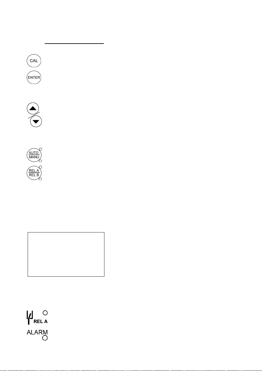
4.1.1 Keypad
•
Perform rapid calibration
Allows entry to Set up mode
•
• Select individual functions within the function group of Set up mode
• Store input data in the Set up mode
• Start calibration in the calibration mode
•
Select various function groups in the Set up mode.
• Set parameters and numerical values in sub functions of Set up mode
If pressed continuously, the setting speed increases
• Control the relays in the MANUAL function
• Return to the Measurement mode when both keys are pressed
together
Switch between AUTO and MANUAL relay operation using a code
•
•
Display limit set-point values for the switch contacts in AUTO relay
operation mode
• Switch between RELAY A and RELAY B in MANUAL relay operation
mode
4.1.2 Display
The LCD display features two numerical displays that sho w status messages and
measured values for easy, quick reference. The display provides short-text
information for setting parameters and configuration.
HOLD
SETUP MEAS CAL
READY
-8.8.8.8
8
-1.8.8.8
Display for RELAY A/B. Green LED indicates measured value within
•
•
Alarm display if limit value overshoot or the ATC connection is broken.
limit while RED LED indicates measured value outside limit.
• HOLD: Relay position and current output are
frozen
• SETUP: Set-up mode of function groups
• MEAS: Measurement mode
• CAL: Calibration mode of Conductivity
• READY: Comes on after a successful
calibration
• ATC: Comes on in the ATC mode. Disappears
in the Manual temperature Compensation
mode. “ATC” flashes if the temperature probe
is faulty in its ATC mode
• 8: Indicates the measurement range selected.
Refer to Appendix 2.
°
ATC
mS
μ
S
C
5
Page 14

Operating Instructions Thermo Scientific Alpha COND 1000
4.2 Function Groups
The main function and sub-function groups are organised in a matrix format for
configuration and selection of parameters. The main function groups are:
1) Temperature Coefficient settings (
2) Temperature Measurement / compensation settings (SEt
3) Control relay 1 configuration (SP1). See Section 7.3.
4) Control relay 2 configuration (
5) Control type (Cntr). See Section 7.4.
6) Current output (rng). See Sections 7.5 & 7.6.
7) Configuration (
8) Calibration (CAL Con). See Sections 6 & 7.8.
HOLD SETUP HOLD SETUP HOLD HOLDSETUP SETUP
ConF). See Section 7.7.
tc). See Section 7.1.
SP2). See Section 7.3.
o
C). See Section 7.2.
Sp1 Sp2
°
C
HOLD SETUP
HOLD SETUP HOLD SETUP
HOLD SETUP
Cal
C
The set-up parameters can be viewed or changed by entering a security code. See
Section 5.2 for security code information.
4.2.1 How to view operating parameters without access to change them:
a) Press the ENTER key. The display will prompt the
user to enter a security code (S.Cd). Leave the
security code at “000” (do not enter a security code).
b) Press ENTER key again. This allows you only to
view (not change) any sub-functions’ settings.
c) Press the ▲ or ▼ keys to scroll through the sub-
functions.
d) Press the ENTER key at a particular sub-function to view in detail.
e) Press the ENTER key to return to the sub-function menu.
f) Press the ▲ or ▼ keys simultaneously (as an Escape key) at any time to return
to the Measurement mode.
Note: To simplify operations, the controller will not display parameters that are not
relevant to a particular sub-function. For example: If the user set the controller for
Limit control, it will not display pulse length/frequency settings.
000
6
Page 15

Operating Instructions Thermo Scientific Alpha COND 1000
4.3 Control Concept
The main function and sub-function groups are organised in a matrix format as
shown below. These functions can be accessed via the front keypad for
configuration and selection of parameters.
MEASURE
CODE
tc
SET C
SET-POINT 1
SET-POINT 2
CONTROLLER
OUTPUT
RANGE
CONFIGURATION
CALIBRATION
Temp Coeff Pur / Lin Set Coeff
Switch On /
Off ATC
Set value 1
Set value 2
Controller type
Range
Selection
Set Filter
Function
Set Cell
Constant K
Process temp.
(MTC)
MIN / MAX
Function
MIN / MAX
Function
N.O./N.C.
contact
Current Ouput
0..20 / 4..20 mA
Calibrate to
Stan dar d
Calib. temp.
(MTC)
Hysteresis 1
Hysteresis 2
Proportional
Band
Conductivity
at 0/4 mA
Display Cal
Ratio
Calibrate Pt100
Pick-up delay
contact 1
Pick-up delay
contact 2
Cycle time
Conductivity
at 20 mA
Dropout delay
contact 1
Dropout delay
contact 2
Line Resistance
Adjustment
Select /Load
Factory Default
The controller offers two levels of password protection: (1) for direct access to
calibration function and (2) for setting or editing specific controller parameters or
functions in the SETUP mode to suit individual requirements.
Note: The passwords are not user-defined and have been set by factory. It is ver y
important to keep these passwords strictly confidential to avoid unauthorised
tampering of the system at all times.
Note: If the user reads parameters only, the controller automatically reverts to
Measurement mode if none of the keys is pressed for 30 seconds.
7
Page 16

Operating Instructions Thermo Scientific Alpha COND 1000
5 MEASUREMENT
5.1 Display in Measurement mode
When the controller is initially powered on, it automatically enters into the
Measurement mode after the large dual LCD displays all segments briefly.
The upper display shows the measured Conductivity value, while the lower display
shows the temperature value. Annunciators at the right side of the display indicate
whether the controller is set for μS or mS measurement. Similarly annunciators or
icons at the top or left side of the display shows the current status of controller, e.g.
“HOLD”, “SETUP”, “MEAS”, “CAL”, “READY”, etc.
5.1.1 Check electrode performance
To read current electrode slope and offset values without changing them:
1) Press the CAL key followed by the ENTER key without adjusting the security
code (leave code at “000”). The upper display shows the condition of the probe.
The lower display reading shows the temperature reading.
Note: If security code is changed to a value other than “000”, pressing the
ENTER key will return to the Measurem ent mode, without displaying electrode
information.
2) Press the ENTER key a second time to return to Measurement mode.
5.1.2 Checking set points
To read current set point values without changing them:
• Press the RELAY Selection (Rel A / Rel B) key. The upper display shows
the set point for Relay A; the lower display shows “SP1”.
• After two seconds the upper display shows the set-point value for Relay B;
the lower display shows “SP2”.
• After an additional two seconds, the controller returns to the Measurement
mode.
8
Page 17

Operating Instructions Thermo Scientific Alpha COND 1000
5.2 Security Codes
This controller has two levels of security protection with separate security codes.
The first level allows entry into the Calibration mode: security code = 11; the second
allows entry into the SETUP mode: security code = 22.
The security codes protect the controller from unauthorised tampering of its current
setting. The parameters cannot be changed unless the security code is entered.
5.2.1 How to enter and change parameters in Calibration mode
1) Press the CAL key. The upper display shows “000”
and the lower display shows “C.Cd” to prompt the
user to enter the Calibration security code.
2) Press the ▲ or ▼ keys to scroll upper display to
Calibration security code “11”.
3) Press the ENTER key. The display shows “CAL
CON”.
4) Press ENTER key again to begin calibration. Refer to Section 6 for full details on
calibration.
5) Press the ▲ or ▼ keys simul taneously (escape) to return to the Measurement
mode.
NOTE: To view (not change) the SETUP parameters, push the ENTER key
when the security code reads “000”.
5.2.1.1 Clearing the Calibration security code from the di sp lay
The calibration security code automatically resets from “11” to “000” after you return
to Measurement mode, so you do not need to clear the security code from the
display.
5.2.2 How to enter and change parameters in Advanced Setup mode
1) Press the ENTER key once. The upper display shows “000” and the lower
display shows “S.Cd” to prompt you to enter the Advanced Setup security code.
2) Press the ▲ or ▼ keys to scroll the display to Setup securi ty code “22”. NOTE:
Pressing the ENTER key at a value other than “22” causes the controller to
revert to the Measurement mode.
3) Press the ENTER key.
4) The upper display reads “tc”.
5) You are now in the Advanced Setup mode. See Section 7 for complete
instructions. To return to Measurement mode, press the ▲ or ▼ keys
simultaneously (escape).
NOTE: If you want to view (not change) set up parameters, push the ENTER
key when the security code reads “000”.
11
9
Page 18

Operating Instructions Thermo Scientific Alpha COND 1000
5.2.2.1 Clearing the Advanced Setup securit y code from the d i splay
After you have entered the security code and returned to the Measurement mode,
the security code “22” still appears on the display whenever you press the ENTER
key. To conceal the security code, you must manually reset the code. To clear the
Advanced Setup security code from the display:
1) Press the ENTER key in the Measurement mode.
2) Set to any security code (not 11 or 22) and complete by pressing ENTER.
NOTE: When you enter the Calibration mode with code “11” or Advanced Setup
mode with security code “22”, the unit automatically enters into the HOLD mode
until you return back to Measurement mode. The HOLD annunciator is
displayed at the upper left of the display. While on HOLD, the current out put is
frozen and set point relays are deactivated.
10
Page 19

Operating Instructions Thermo Scientific Alpha COND 1000
6 CALIBRATION MODE
You can reach the Calibration mode directly from the Measurement mode by
pressing the CAL key and entering the Calibration security code. You can also
reach the Calibration mode from the Advanced Setup mode.
6.1 Conductivity Calibration
Calibration is always carried out in the specific range selected. The Conductivit y
Controller allows a one-point calibration.
1) Enter Calibration mode. While in the Measurement
mode, push the CAL key and scroll to Calibration
code “11”. Push the ENTER key again. The upper
display reads “CAL” and the lower display shows
“Con”.
2) Press the ENTER key. The controller displays its
last set Cell Constant (k) of the cell as a percentage
of the theoretical value. Using the ▲and ▼ keys, the
value can be set to anywhere from 80 to 120% (e.g.
real cell constant is 0.98 with nominal =1, enter
98%). . Press the ENTER key once again to carry
out calibration.
3) Immerse the Conductivity cell in a suitable standard
solution, whose value is within the measurement
range selected in the controller. Agitate the Cell in
the solution to remove any trapped air-bubbles.
Note: The calibration standard should have a value that
is between 20% to 100% of the range selected. For
example, if the range in the controller is selected to be
2000 µS (range 6), then the calibration standard value
should be 400 µS to 2000 µS.
4) Once the reading has stabilized, use the ▲ or ▼
keys to adjust the measured value to that of the
standard solution. Press the ENTER key to accept the value and the controller
displays the revised condition of the probe. The lower display shows the factor
“FCt” while the upper display shows the ratio of ideal to adjusted calibration
value.
Note: The acceptable calibration window is ±40% of the displaye d (default) value. If
the display is 1000 µS, the values to which it can be adjusted is 6 00 to 1400 µS. If
there is calibration error, the controller displays “ERR” annunciator. To re-calibrate
repeat step 3. To exit from calibration, push both ▲ and ▼keys (escape) to resume
to Measurement mode.
5) Press the ENTER key. If you entered the calibration mode using the CAL key,
the controller will return to the Measurement mode. If you entered the calibration
mode from the Advanced Set-up mode, the controller will return to the subfunction menu.
HOLD
SETUP
6
HOLD
100.0
6
HOLD
1413
6
HOLD
1.01
6
Cal
C
CAL
CEL
CAL
25.0
CAL
fc
%
μ
S
°
C
ATC
11
Page 20

Operating Instructions Thermo Scientific Alpha COND 1000
Note: When calibrating with manual temperature compensation, the controller
automatically changes from the preset process temperature to the calibration
temperature. After leaving the Calibration mode, the controller switches back to
process temperature (for setting the calibration temperature and the process
temperature, see section 7.2.1).
12
Page 21

Operating Instructions Thermo Scientific Alpha COND 1000
7 ADVANCED SET-UP MODE
7.1 Tempera ture Coefficient sub-function
This sub-function allows you to select the correct temperature coefficient for
optimum operations. For applications in the pure water or ultra-pure water industries,
simply select the “Pur” temperature coefficient option. For all other applications,
select “Lin” temperature coefficient. The controller allows further input of
temperature coefficient values, independently for the process and for the calibrating
solutions. Default is at 2.10 %.
HOLD HOLD
HOLD
L
SETUP
HOLD
SETUP
2.10 2.10
P. C.
%%
ATC ATC
HOLDSETUP SETUP
SETUP
P
7.1.1 Selecting Pure-water or Linear Temperature Coefficient
1) Enter Advanced set-up mode. Push the ENTER key and
HOLD
use ▲ or ▼ keys to scroll to Advanced Set-up security
code “22”.
2) Push the ENTER key. Controller displays “tc”.
3) Push ENT ER key again and use ▲ or ▼ keys to select
between “Pur” and “Lin” temperature coefficients.
4) If “Pur” tC is be selected, press the ENTER key and
HOLD
controller goes back to “tC”. If “Lin” tC is selected, press
the ENTER key and proceed to step 5.
5) The upper display shows “2.10%”, while the lower
display show “P.tC”. This option allows you to input the
Process Temperature coefficient, from 0 to 10%. Default
is 2.10%. Use the ▲ or ▼ keys to enter the required
HOLD
temperature coefficient value.
6) Press the ENTER key. Next, enter the temperature
coefficient of the calibration solution (0 to 10%). Default
is 2.10%.
7) Press the ▲ or ▼ keys to input the desired calibration
solution temperature coefficient.
HOLD
8) Press the ENTER key to accept the value.
9) Continue with additional Advance setup procedures or
return to Measurement mode by pressing the ▲ and ▼
keys (escape) simultaneously.
13
SETUP
SETUP
L
SETUP
2.10
P.
SETUP
2.10
C.
%
ATC
%
ATC
Page 22

Operating Instructions Thermo Scientific Alpha COND 1000
7.2 Tempera ture Calibration (ATC mode only)
1) Enter Advanced Set-up mode. Push the ENTER key and
(use ▲ or ▼ keys to) scroll to Advanced Set-up security
code “22”. Push the ENTER key again.
2) Press the ▲ or ▼ keys to scroll until the display shows
“SEt ºC”. Push ENTER key.
3) Press the ▲ or ▼ keys to select “on ATC”. Press ENTER
key.
4) The upper display indicates the current temperature offset.
The current measured temperature is shown in the lower
display.
5) Compare the current measured temperature on the
controller display to a thermometer known to be accurate.
Note down the correct temperature.
6) Press the ▲ or ▼ keys to scroll the lower display to
match the correct value. The upper display will now show
the offset value. You can offset temperature up to ± 5 ºC.
7) Press the ENTER key to confirm your selection.
8) Continue with additional Advanced Set-up procedures, or return to the
Measurement mode by pressing the ▲ and ▼ keys (escape) simultaneously).
7.2.1 Setting Manual Temperature Compensation
NOTE: This parameter is blanked out when the controller is
set for ATC operation.
For manual temperature compensation, you can set two
different temperatures: Process and Calibration. This allows
calibration at a temperature other than your process
temperature. Example: setting a calibration temperature of 25
ºC lets you calibrate using standard buffer solutions at 25 ºC,
even if your process temperature is at different temperature.
1) Enter Advanced Set-up mode. Push the ENTER key and
(use ▲ or ▼ keys to) scroll to Advanced Set-up security
code “22”. Push the ENTER key again.
2) Press the ▲ or ▼ keys to scroll until the display shows
“SEt ºC”. Push ENTER key.
3) Press the ▲ or ▼ keys to select “oFF ATC”. Press
ENTER key.
4) The upper display shows the current process temperature
and the lower display shows “P. ºC” to indicate process temperature.
5) Press
the ▲ or ▼ keys to adjust the process temperature value. You can
adjust the value from -9.9 to 125 ºC.
HOLD SETUP
HOLD
SETUP
A
HOLD
SETUP
0.0
25.0
HOLD
SETUP
HOLD
SETUP
25.0
P. c
HOLD
SETUP
25.0
C.
A
°
FF
c
C
°
C
ATC
°
C
°
C
14
Page 23

Operating Instructions Thermo Scientific Alpha COND 1000
μ
6) After you set the process temperature value, press the ENTER key. The upper
display shows the current calibration temperature and the lower display shows
“C.ºC” to indicate calibration temperature.
7) Press the ▲ or ▼ keys to adjust the calibration temperature value. You can
adjust the value from -9.9 to 125 ºC.
8) Press ENTER key to confirm your selection.
9) Continue with additional Additional Set-up procedures, or return to
Measurement mode by pressing the ▲ and ▼ keys (escape) simultaneously).
7.3 Control Relay A/Control Relay B (SP1/SP2) sub-function
The SP1 option sets the operating parameters for Relay A; and SP2 for relay B.
Since these groups have the same set-up parameters, they are described together.
HOLD HOLD HOLD HOLD HOLD HOLDSETUP SETUP SETU P SETUP SET UP S ETUP
Sp1 100 L 20 0 0
666
μ
S
Sp1 Sp1 Hys O . OF.
7.3.1 Entering the Set point 1 (or Set point 2) sub-function
S
66
The alpha CON 1000 controller/transmitter can operate in either one of the 10
different conductivity ranges (see Section 12.2 – Appendix 2: Measureme nt Ranges
Available in the Controller. Refer to Section 7.5.1 for Selecting the Measuring
Range sub-function.
1) Enter Advanced Set-up mode. Push the ENTER key and
(use ▲ or ▼ keys to) scroll to Advanced Set-up
security code “22”. Push the ENTER key again.
2) Press the ▲ or ▼ keys to scroll until the upper display
shows SP1 (or SP2).
7.3.2 Selecting the set point values
This lets you choose the value that will cause your controller
to activate (Default: SP1 = 100 µS; SP2 = 1900 µS).
1) Press the ENTER key until upper display shows the
current set point value and the lower display shows SP1
(or SP2).
2) Press the ▲ or ▼ keys to select your value for Set point 1
(or Set point 2). Your controller will activate at the value
you select.
3) Press the ENTER key to confirm your selection.
4) Proceed to 7.3.3, or return to Measurement mode by
pressing the ▲ and ▼ keys simultaneously (escape).
HOLD
HOLD
6
HOLD
6
SETUP
Sp1
SETUP
100
Sp1
SETUP
L
Sp1
μ
S
15
Page 24

Operating Instructions Thermo Scientific Alpha COND 1000
7.3.3 Choosing High or Low set points
Select a low set point to activate controller when the conductivity value
undershoots the low set point; select a high set point to activate controller when the
value overshoots the high set point. Using both SP1 and SP2, you can select lo/lo,
lo/hi, hi/lo, or hi/hi set points (Default: SP1 = Lo; SP2 = Lo).
1) Follow directions in 7.3.1 to enter Control Relay mode.
2) Press the ENTER key. Scroll with the ▲ or ▼ keys until the upper display
shows Lo or Hi (for low or high set point) and the lower display shows SP1 (or
SP2).
3) Press the ▲ or ▼ keys to select low (lo) or high (hi) set point for SP1 (or SP2).
4) Press the ENTER key to confirm your selection.
5) Proceed to 7.3.4, or return Measurement mode by pressing the ▲ and ▼ keys
simultaneously (escape).
7.3.4 Selecting a hysteresis (dead band) value
Hysteresis prevents rapid contact switching if your value is fluctuating near the set
point. It does this by overshooting the set point value to a specified hysteresis value
Example: You have set your set point 1 (Lo) at 100.0 μS and your hysteresis limit
value is at 20 μS. If your measured value undershoots the low set point of 100.0 μS,
the controller’s relay activates, which in turn activates an external device such as a
pump or valve. The actions of the external device will cause the value to r ise above
100.0 μS. When the value has increased to 120.0 μS, the relay, and hence the
pump will switch off.
Default hysteresis value in the full scale conductivity range of 2,000 µS (see
Appendix 2) is 20 µS. You can set the hysteresis value from 0 to 10% of the full
scale conductivity range.
1) Follow directions in 7.3.1 to enter Control Relay
mode.
2) Press the ENTER key. Scroll with the ▲ or ▼ keys
until the upper display shows the hysteresis (dead
band) value and the lower display shows “HYS”.
3) Press the ▲ or ▼ keys to enter your hysteresis
value for Set point 1 (or Set point 2). Your controller will activate at the value
you select. Note: All settings for SP1 and SP2 are completely independent of
each other.
4) Press the ENTER key to confirm your selection.
5) Proceed to 7.3.5, or return to Measurement mode by pressing the ▲ and ▼
keys simultaneously (escape).
NOTE: Please refer to Appendix 3 for a graphical representation of the Hysteresis.
HOLD SETUP
20
6
Hys
μ
S
16
Page 25

Operating Instructions Thermo Scientific Alpha COND 1000
7.3.5 Setting an on-delay time lag
You can set as time delay for each relay, which stops the relay from switching o n
the moment the set point is exceeded. This controller lets you set a 0 to 1999
seconds time delay before the relay activates.
1) Follow directions in 7.3.1 to enter Control Relay
mode.
2) Press the ENTER key. Scroll with the ▲ and ▲
keys until the upper display shows “0” time and the
lower display shows “On.d”.
3) Press the ▲ or ▼ keys to enter on-delay time for
Set point 1 (Set point 2). The controller will delay
activation for the number of seconds (0 to 1999) you select.
4) Press the ENTER key to confirm your selection.
5) Proceed to 7.3.6, or return to Measurement mode by pressing the ▲ and ▼
keys simultaneously (escape).
7.3.6 Setting an off-delay time lag
You can set as time delay for each relay, which stops the relay from switching off
the moment the value reached the set point and hysteresis. This controller lets you
set a 0 to 1999 seconds time delay before your relay deactivates.
HOLD SETUP
6
O .
0
1) Follow directions in 7.3.1 to enter Control Relay
mode.
2) Press the ENTER key. Scroll with the ▲ or ▼ keys
until the upper display shows “0” time and the lower
display shows “OF.d”.
3) Press the ▲ or ▼ keys to enter on-delay time for
Set point 1 (Set point 2). Your controller will delay
activation for the number of seconds (0 to 1999) you select.
4) Press the ENTER key to confirm your selection.
5) Continue with Advanced Set-up mode procedures, or return to Measurement
mode by pressing the ▲ and ▼ keys simultaneously (escape).
HOLD SETUP
6
OF.
0
17
Page 26

Operating Instructions Thermo Scientific Alpha COND 1000
7.4 Controller (Cntr) sub-function
You can set the controller’s parameters in this sub-function.
HOLD HOLD
HOLD SETUP
SETUP SETUP
L.c EE
HOLD
YP
SETUP
EL
FF
YP
HOLD
SETUP
PLC
YP
HOLD
SETUP
PFC
YP
7.4.1 Entering the Controller sub-function
1) Enter Advanced Set-up mode. Push the ENTER key and scroll to Advanced
set-up security code “22”. Push the ENTER key again.
2) Press the ▲ or ▼ keys to scroll until the upper display shows “Cntr”.
18
Page 27

Operating Instructions Thermo Scientific Alpha COND 1000
7.4.2 Choosing the controller type (limit or proportional)
This mode lets you choose your controller type: limit control, pulse length
proportional control, pulse frequency proportional control, or control off.
- Use limit control with pumps or values for fast response.
- Use pulse frequency proportional control to operate your p umps smoothly
- Use pulse length proportional control for precise control of proportional
valves.
- Use control off to operate controller as a monitor only or to prevent relays
from switching.
1) Follow directions in 7.4.1 to enter Controller mode.
2) Press the ENTER key. The upper display shows the current controller type and
the lower display shows “tyP”.
3) Press the ▲ or ▼ keys to select your controller type.
- L.Ct = limit value pickup (on/off control).
- oFF = controller off.
- PLC= pulse length control
- PFC= pulse frequency control
4) Press the ENTER key to confirm your selection.
5) Proceed to 7.4.3, or return to Measurement mode by pressing the ▲ and ▼
keys simultaneously (escape).
7.4.3 Choosing Break/Make Contact Relay Type
Note: If the controller type “oFF” is set, the parameters listed in 7.4.3, 7.4.4, and
7.4.5 are blanked out.
This mode lets you determine the relay-state under Non-Alarm condition – dEE N
(de-energised) or EN (energised).
HOLD
HOLD
SETUP
EE
EL
SETUP
E
EL
1) Follow directions in 7.4.1 to enter Controller mode.
2) Press the ENTER key. Scroll until the lower display
shows “rEL” and the upper display shows the current
selection (de-energised = dEEN or energised = EN).
3) Press the ▲ or ▼ keys to choose de-energised or
energised relay state.
4) Press the ENTER key to confirm your selection.
5) Continue with Advanced Set-up mode procedures, or
return to Measurement mode by pressing the ▲ and ▼
keys simultaneously (escape).
19
Page 28

Operating Instructions Thermo Scientific Alpha COND 1000
7.4.4 Selecting Proportional Range Value, Xp
Note: If the controller type “oFF” is set, the parameters listed in 7.4.3, 7.4.4, and
7.4.5 are blanked out.
This mode lets you set a band as a percentage of its full scale valu e. You can select
this range from 10 to 200%, and the lower display shows “PrP”.
1) Follow directions in 7.4.1 to enter Controller mode.
2) Press the ENTER key. Follow directions in 7.4.2 and
select either “PLC” (pulse length control) or “PFC”
(pulse frequency control). Press ENTER key.
3) Press the ENTER key until the upper display shows the
proportional range (a number from 10 to 200%), and the
lower display shows “PrP”.
4) Press the ▲ or ▼ keys to choose the proportional range value Xp.
5) Press the ENTER key to confirm your selection.
6) Proceed to 7.4.5, or return to Measurement mode by pressing the ▲ and ▼
keys simultaneously (escape).
7.4.5 Maximum Pulse Length (tPL) or Maximum Frequency (FPF)
Note: If the controller type “oFF” is set, the parameters listed in 7.4.3, 7.4.4, and
7.4.5 are blanked out.
This mode lets you set the maximum pulse length or the
maximum frequency at which the relay will operate.
1) Follow directions in 7.4.1 to enter Controller mode.
2) Press the ENTER key. Scroll until the lower display
shows “t.PL” or “F.PF”.
a. In PLC (pulse length) mode: The lower display
shows “t.PL” to indicate pulse length. The upper
display shows your current pulse length. You
can select any value from 0.5 to 20 seconds.
b. In PFC (pulse frequency) mode: The lower
display shows “F.PF” to indicate pulse
frequency. The upper display shows your
current maximum pulse rate. You can select any value from 60 to 120
pulses per minute. When the measured value exceeds the Proportional
Band in 7.4.4, the controller will pulse the relay at this rate.
3) Press the ▲ or ▼ key to choose the period duration or maximum frequency,
depending on your mode.
4) Press the ENTER key to confirm your selection and to return to Advanced Set-
up mode, or return to Measurement mode by pressing the ▲ and ▼ keys
simultaneously (escape).
Note: The alarm contact is always of the fail-safe type. In the event of power failure
the alarm is triggered.
HOLD SETUP
100
HOLD
SETUP
10.0
HOLD
SETUP
60
.pl
f.pf
20
Page 29

Operating Instructions Thermo Scientific Alpha COND 1000
7.5 Measurement Range sub-function
HOLD SETUP
In this sub-function, the appropriate range is
selected with the appropriate cell constant.
7.5.1 Selecting the Measuring Range sub-
function
1) Enter Advanced Set-up mode. Push the ENTER
key and scroll to Advanced Set-up security code
“22”. Push the ENTER key again.
2) Press the ▲ or ▼ keys to scroll until the upper
display shows “rng”.
3) Press the ENTER key. The upper display shows
the maximum measurement range, while the lower
display shows the Cell constant. In the lower left-corner of the LCD, the numbe r
corresponding to the respective range is displayed.
4) Press the ▲ or ▼ keys to select the correct range. (Plea se refer to Section
12.2 Appendix 2 for the full list of measurement ranges).
5) Proceed to 7.6 to set current output or return to Measurement mode by
pressing the ▲ and ▼ keys simultaneously (escape).
HOLD SETUP
200.0
4
0.1
μ
S
21
Page 30

Operating Instructions Thermo Scientific Alpha COND 1000
7.6 Current Output (rng) sub-function
This sub-function lets you set the transmitter current output range of this unit. T he
difference between the upper and lower range has to be a minimum of 20% of Full
Scale, anywhere on the scale.
7.6.1 Entering current output sub-function
1) Enter Advanced Set-up mode. Push the ENTER key
and scroll to Advanced Set-up security code “22”.
Push the ENTER key again.
2) Press the ▲ or ▼ keys to scroll until the upper
display shows “rng”. Press ENTER.
3) Measurement range selection. Please refer to 7.5.
Press ENTER to proceed to current output subfunction (7.6.2)
7.6.2 Choosing the output type
This parameter lets you choose between 0-20 mA or 420 mA output.
1) Follow directions in 7.6.1 to enter Current Output
mode.
2) Press the ENTER key. Scroll with the ▲ or ▼ keys
until the upper display shows the output type (0-20 or
4-20), and the lower display shows “out”.
3) Press the ▲ or ▼ keys to select your output type: 0-
20 or 4-20 mA.
4) Press the ENTER key to confirm your selection.
5) Proceed to 7.6.3, or return to Measurement mode by
pressing the ▲ and ▼ keys simultaneously (escape).
7.6.3 Selecting Conductivity value at 0(4)mA
This parameter lets you choose the conductivity value at
which the transmitter output will be 0(4) mA.
1) Follow directions in 7.6.1 to enter Current Output
mode.
2) Press the ENTER key. Scroll with the ▲ or ▼ keys until the upper display
shows a conductivity value and the lower display shows “r.0(4)”.
3) Press the ▲ or ▼ keys to select the required conductivity value to be
equivalent to 0(4) mA (0.00 to 80.0 % F.S.; Default is 0% F.S.).
4) Press the ENTER key to confirm your selection.
5) Press the ENTER ke
y to return to Advanced Set-up mode, or return to
Measurement mode by pressing the ▲ and ▼ keys simultaneously (escape).
22
HOLD SETUP
HOLD
SETUP
200.0
0.1
4
HOLD
SETUP
4-20
4
SETUP
HOLD
0.0
4
SETUP
HOLD
200.0
4
.20
μ
S
μ
S
μ
S
Page 31

Operating Instructions Thermo Scientific Alpha COND 1000
7.6.4 Selecting Conductivity value at 20mA
This parameter lets you choose the conductivity value at which the transmitter
output will be 20mA.
1) Follow directions in 7.6.1 to enter Current Output mode.
2) Press the ENTER key. Scroll with the ▲ or ▼ keys until the upper display
shows a conductivity value and the lower display shows “r.20”.
3) Press the ▲ or ▼ keys to select the required conductivity value to be
equivalent to 20 mA (20.0 to 100.0% F.S.; Default is 100% F.S.).
4) Press the ENTER key to confirm your selection.
5) Press the ENTER key to return to Advanced Set-up mode, or return to
Measurement mode by pressing the ▲ and ▼ keys simultaneously (escape).
7.7 Configuration (ConF) sub-function
This group of parameters lets you configure the controller to suit your requirements.
7.7.1 Entering the Configuration sub-function
1) Enter Advanced Set-up mode. Push the ENTER key and scroll to Advanced
Set-up security code “22”. Push the ENTER key again.
2) Press the ▲ or ▼ keys to sc roll until the upper display shows “ConF”. Press
ENTER key to enter configuration sub-function.
7.7.2 Selecting Filter Function and the Alarm or Wash Function
In this configuration sub-function, you have the ‘Filter’ selection
which lets you filter rapid measurement changes and stabilising
the measurement. This configuration sub-function also allows
you to use the Alarm relay as Wash or Clean contact. The Wash
(Clean) contact is used in combination with automatic cleaning
systems. During the wash cycle, the analog output is set on hold.
1) In Filter selection mode, use the arrow keys to choose filter
"on" or "off".
2) Press the ENTER key to confirm. Display will now show
“ALr” or “CLn”.
3) Press the ▲ or ▼key to choose "ALr" (Alarm) or "CLn"
(Clean) function.
23
Page 32

Operating Instructions Thermo Scientific Alpha COND 1000
4) Press the ENTER key to confirm your selection.
5) Procee d to 7.7.3, or return to Measurement mode by pressing the ▲ and ▼
keys simultaneously (escape).
Note: The factory default setting for the Filter selection is "on".
7.7.3 Selecting the alarm time lag
This parameter group lets you select a period of time
before the alarm activates when your set point has been
overshot. You can select from 0 to 1999 seconds.
1) Follow directions in 7.7.1 to enter Configuration mode.
2) Press the ENTER key. Scroll with the Δ or ∇ keys
until the upper display shows a numerical value (in
seconds) and the lower display shows “AL.d”.
3) Press the ▲ or ▼ keys to select how long of an alarm delay (0 to 1999
seconds) you want.
4) Press the ENTER key to confirm your selection.
5) Proceed to 7.7.4, or return to Measurement mode by pressing the ▲ and ▼
keys simultaneously (escape).
7.7.4 Selecting steady or pulse contact for the alarm relay
This parameter group lets you select whether the alarm
contact will operate as a steady contact or a fleeting (single
pulse) contact. Pulse contact closing time is 250 millisecond.
1) Follow directions in 7.7.1 to enter Configuration mode.
2) Press the ENTER key. Scroll with the ▲ or ▼ keys until
the upper display shows “Stdy” or “FLEt” and lower
display shows “AL.C.”.
- AL.C = alarm contact
- StdY = steady contact
- FLEt = fleeting (single pulse) contact
3) Press the ▲ or ▼ keys to select steady or pulse
contact.
4) Press the ENTER key to confirm your selection.
5) Proceed to 7.7.5, or return to Measurement mode by pressing the ▲ and ▼
keys simultaneously (escape).
HOLD SETUP
30
Al.
HOLD
SETUP
S Y
Al.C
HOLD
SETUP
FLE
Al.C
24
Page 33

Operating Instructions Thermo Scientific Alpha COND 1000
7.7.5 Wash contact (if the relay 3 is set to Wash)
1) Follow directions in 7.7.1 to enter Configuration mode.
2) Press the ENTER key until display shows “ALr” or “CLn”.
Choose “CLn” by pressing ▲ or ▼ key. Press the
ENTER key.
3) Press the ▲ or ▼ key to select the wash cycle (interval
0.1 to 199.9 hours) and press the ENTER key to confirm.
4) Press the ▲ or ▼ key to select the wash duration (1 to
1999 seconds) and press the ENTER key to confirm.
5) Proceed to 7.7.6, or return to Measurement mode by
pressing the ▲ and ▼ keys simultaneously (escape).
7.7.6 Input Line Resistance Adjust
This function compensates for the line resistance of the cable to its cell.
HOLD
HOLD
SETUP
10.0
i
SETUP
10
1) Follow directions in 7.7.1 to enter Configuration mode.
2) Press the ENTER key. Scroll with the ▲ or ▼ keys
until the upper display shows “0.0” and lower display
shows “L.Ad”.
- L.Ad = line adjuster resistance (0.0 to 100.0)
3) Press the ▲ or ▼ keys to input the value.
4) Press the ENTER key to confirm your selection.
5) Proceed to 7.7.7, or return to Measurement mode by pressing the ▲ and ▼
keys simultaneously (escape).
7.7.7 Reverting to factory default settings
HOLD
SETUP
0.0
L.a
Use this parameter to reset all settings to factory default.
Changing from “no” to “YES” and pressing the ENTER
key resets all settings to factory default.
WARNING: If you select yes, all the settings you have
made will be overwritten as a result!
1) Follow directions in 7.7.1 to enter Configuration mode.
2) Press the ENTER key. Scroll with the ▲ or ▼ keys
until the upper display shows “no” or “YES”, and the lower display shows “deF”
(default).
3) Press the ▲ or ▼ keys to select no or yes. Selecting “YES” and pressing the
ENTER key will overwrite all setting you have made and automatic ally return
you to Measurement mode.
4) Press the ENTER key to confirm your selection and to return to Advanced Setup mode, or return to Measurement mode by pressing the ▲ and ▼ keys
simultaneously (escape).
25
HOLD SETUP
EF
Page 34

Operating Instructions Thermo Scientific Alpha COND 1000
7.8 Calibra tion (CAL) sub-function
The calibration procedure in Advanced Set-up mode is identical to the proced ure in
the Calibration mode. The only difference is that the controller will revert back to
Set-up mode (instead of Measurement mode) after calibration is completed.
7.8.1 Entering Calibration mode from Advanced Set-up mode
1) Enter Advanced Set-up mode. Push the ENTER key and scroll to Advanced
Set-up security code “22”. Push the ENTER key again.
2) Press the ▲ or ▼ keys to scroll until the upper display shows “CAL”.
3) See section 6 for complete calibration procedures.
26
Page 35

Operating Instructions Thermo Scientific Alpha COND 1000
8 AUTO/MANUAL MODE
Regardless of the mode, you can control devices connected to Relay A or Relay B
from the front panel of this controller. In Automatic mode, the controller’s set point
values activate the relays. In Manual mode, you have manual control of the relays
so you can prime the pump or check pump status without operating the entire
system.
8.1 Auto mode (mode after s witch-on)
In this mode, the controller set-point values activate the relays. To view the setpoint values:
1) Press the RELAY SELECTION (Rel A/Rel B) key. The upper display shows
your set-point value for Relay A; the lower display shows “SP1”.
2) After two seconds the upper display shows your set-point value for Relay B; the
lower display shows “SP2”.
3) After an additional two seconds the controller will return to Measurement mode.
8.2 Manual mode
In this mode, you can manually turn on and off the control devices connected to
Relay A or Relay B or both.
1) Press the RELAY CONTROL (auto/manu) key. The upper display shows
“000”; the lower display shows “S.Cd” to prompt you to enter the Advanced Setup code.
2) Press the ▲ or ▼ keys to scroll the upper display until it reads “22”.
3) Press the ENTER key. The manual indicator by the RELAY CONTROL key
lights up.
Note: Pressing ENTER key at a value other than “22” will cause the controller to
revert to Measurement mode, and the relays will remain in automatic mode.
4) Press the RELAY SELECTION key to select either R elay A or Relay B. The
LED next to the currently selected relay (A or B) will light.
The manual control options are now available.
- If you selected Limit control: The upper display reads the current
measured value. The lower display shows “oFF” or “on” depending on
the relay status of the currently selected relay.
5) Press the ▲ or ▼ keys to change the Relay on/off status. T he LED indicators
at the right of the controller will also change between Red and Green to indicate
Relay status.
Note: If you wish to manually change the status of both relays, press the RELAY
SELECTION key at this point and repeat step 5 for the second relay. This first relay
will remain under manual control while you are setting the second relay.
6) Press the RELAY CONTROL key to return to Measurement mode. The relays
are now back under automatic control.
27
Page 36

Operating Instructions Thermo Scientific Alpha COND 1000
9 TECHNICAL SPECIFICATIONS
Conductivity Range Resolution Default Cell
Constant, K
0.000 to 1.999 μS/cm 0.001 μS/cm
0.00 to 19.99 μS/cm 0.01 μS/cm
0.0 to 199.9 μS/cm 0.1 μS/cm
0 to 1999 μS/cm 1 μS/cm
0 to 5000 μS/cm 5 μS/cm
0.01 -
0.01 0.1
0.1 1.0
1.0 -
1.0 -
0.00 to 19.99 mS/cm 0.01 mS/cm 1.0 -
0.0 to 199.9 mS/cm 0.1 mS/cm 10.0 1.0
Temperature 0-50
Resolution
Relative Accuracy
o
C (Display: -9.9 to 125 oC)
0.1
± 0.5
Sensor Pt 1000/Pt 100
Temperature Compensation Auto / manual (reference at 25.0 oC)
Set-point and Controller Functions
Controller characteristics Limit / proportional (pulse or frequency) controller
Pickup / Dropout delay 0 to 1999 sec.
Switching Condutivity hysteresis 0 to 10% of Full Scale
Contact outputs, controller 2 potential-free change-over contacts
Switching voltage max. 250 VAC
Switching current max. 3A
Switching power max. 600 VA
Alarm Functions
Function (switchable) Latching / pulse
Pickup delay 0 to 1999 sec.
Switching voltage max. 250 VAC
Switching current max. 3A
Switching power max. 600 VA
Electrical Data and Connections
Power Requirements 110 / 220 VAC (jumper selectable)
Frequency 48 to 62 Hz
Signal Output 0/4 to 20 mA, galvanically isolated
Signal Output Load
max. 600 Ω
Connection terminal Terminal blocks 5-pole / 17-pole, removable
Mains fuse / fine wire fuse slow-blow 250 V / 100 mA
EMC Specifications
Emissions According to EN 50081-1
Susceptibility According to EN 50082-1
Environmental Conditions
Ambient temp. operating range 0 to 50 oC
Relative humidity 10 to 95%, non-condensing
Mechanical Specifications
Dimensions (control panel housing -
175 x 96 x 96 mm
L x H x W)
Weights (control panel housing) max. 0.7 kg
Material ABS with polycarbonate (front housing)
Insulation (Front / Housing) IP 54 / IP 40
28
Optional Cell, K
o
C
o
C
Page 37

Operating Instructions Thermo Scientific Alpha COND 1000
10 ACCESSORIES
Assembly Accessories
Product Description Code no.
Conductivity Cell, up to 20μS; Cell constant, K=0.01 with
integrated Pt 100, Material SS316 and 25ft cable (open-ended)
Conductivity Cell, up to 20μS; Cell constant, K=0.01 with
integrated Pt 100, Material Titanium and 25ft cable (openended)
Conductivity Cell, 0.1 - 200μS; Cell constant, K=0.1 with
integrated Pt 100, Material SS316 and 25ft cable (open-ended)
Conductivity Cell, up to 200 mS; Cell constant, K=1.0 with
integrated Pt 100, Material SS316 and 25ft cable (open-ended)
Note: Above Conductivity Cells can withstand a pressure of up to 6 bar. Please ask
your authorised distributor or dealer for the prices.
EC-CS10-0-01S
EC-CS10-0-01T
EC-CS10-0-1S
EC-CS10-1-0S
11 GENERAL INFORMATION
11.1 Warranty
Thermo Scientific warrants this product to be free from significant deviations in
material and workmanship for a period of one year from the date of purchase. If
repair is necessary and has not been the result of abuse or misuse within the
warranty period, please return by freight pre-paid and amendment will be made
without any charge. Our Customer Service Dept. will determine if product
problem is due to deviations or customer abuse. Out of warranty products will be
repaired on a charge basis.
11.2 Packaging
The instrument is packaged in a corrugated box with a warranty card, instruction
manual and the following accessories:
- 17-way and 5-way (right-angled) terminal block [1 unit each]
- side threaded rod with catch [2 units]
- receptacle cable lug [1 unit]
- rubber gasket [1 unit]
11.3 Return of Goods
Authorisation must be obtained from our Customer Service Dept. to issue a RMA
(Return of Material Authorisation) number before returning items for any reason.
When applying for authorisation, please include data requiring the reason of return.
Items must be carefully packed to prevent damage in shipment and insured against
possible damage or loss. Thermo Scientific will not be responsible for any damage
resulting from careless or insufficient packing.
Warning: Shipping damage as a result of inadequate packaging is the
user/distributor’s responsibility, whoever applicable. Please follow the
guidelines below before shipment.
29
Page 38
Operating Instructions Thermo Scientific Alpha COND 1000
o
g PC
11.4 Guidelines for Returning Unit for Repair
Use the original packaging material, if possible when shipping the unit for repair.
Otherwise wrap it with bubble pack and use a corrugated box for better protection.
Include a brief description of any faults suspected for the convenience of Customer
Service Dept., if possible.
12 APPENDICES
ENSURE that the power cable is physically separated from the power
.
supply
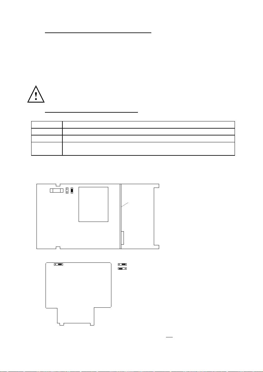
12.1 Appendix 1 – Jumper Positions
Jumper Positions - Internal to the controller
JP 1 Selects the input voltage 220 VAC.
JP 2 Selects the input voltage 110 VAC.
JP 6 Selects the temperature sensor for Pt1000/Pt100
Fuse
JP6 On the Anal
Selects between Pt100 and Pt1000. To switch between Pt
tweezers or needle nose pliers to shift jumper from Position A to Position B.
r
a
e
R
Note that there is a fuse (slow-blow 100mA) internal to the
controller. Replace fuse with the recommended type only.
B:
JP2
JP1
Fuse
C
C
A
A
V
V
0
0
3
1
1
2
100 and Pt100 0, use
Analog PCB
t
n
o
r
F
JP6
View from the top of Main PCB
JP6
BA A -Pt100
View from the front of the Analog PCB
B - Pt1000
30
Page 39

Operating Instructions Thermo Scientific Alpha COND 1000
12.2 Appendix 2 – Measurement Ranges available in the Controller
Range No. Range Resolution Default cell K
1
2
3
4
5
6
7
0.000 – 1.999 μS 0.001 μS
0.00 – 19.99 μS 0.01 μS
0.00 – 19.99 μS 0.01 μS
0.0 – 199.9 μS 0.1 μS
0.0 – 199.9 μS 0.1 μS
0 – 1999 μS 1 μS
0 – 5000 μS 5 μS
0.01
0.01
0.1
0.1
1.0
1.0
1.0
8 0.00 – 19.99 mS 0.01 mS 1.0
9 0.0 – 199.9 mS 0.1 mS 10.0
0 0.0 – 199.9 mS 0.1 mS 1.0
12.3 Appendix 3 – Conductivity at Related Temperature Coefficients
(25 °C)
Substance Concentration wt % Conductivity 10-4 S/cm Conductivity
NaOH 5 1969 2.01
10 3124 2.17
15 3463 2.49
20 3270 2.99
30 2022 4.50
40 1164 6.48
KOH 25.2 5403 2.09
(15 C) 29.4 5434 2.21
33.6 5221 2.36
42.0 4212 2.83
NH3 0.10 2.51 2.46
(15 C) 1.60 8.67 2.38
4.01 10.95 2.50
8.03 10.38 2.62
16.15 6.32 3.01
30.5 1.93 -
HF 1.5 198 7.20
4.8 593 6.66
24.5 2832 5.83
HNO3 6.2 3123 1.47
12.4 5418 1.42
31.0 7819 1.39
49.6 6341 1.57
62.0 4964 1.57
Coefficient
31
Page 40

Operating Instructions Thermo Scientific Alpha COND 1000
Substance Concentration wt % Conductivity 10
-4
S/cm Conductivity
Coefficient
H3PO4 10 566 1.04
(15oC) 20 1129 1.14
40 2070 1.50
45 2087 1.61
50 2073 1.74
NaCl 5 672 2.17
10 1211 2.14
15 1642 2.12
20 1957 2.16
25 2153 2.27
Na2SO4 5 409 2.36
10 687 2.49
15 886 2.56
HCl 5 1969 1.58
10 3124 1.56
20 3463 1.54
30 662 1.52
40 5152 -
H2SO4 5 2085 1.21
10 3915 1.28
20 6527 1.45
40 6800 1.78
50 54055 1.93
60 3726 2.13
80 1105 3.49
100.14 187 0.30
CuSO4 5 109 2.13
10 189 2.16
20 320 2.18
30 421 2.31
CH3COOH 1 5.84 -
10 15.26 1.69
15 16.19 1.74
20 16.05 1.79
30 14.01 1.86
40 10.81 1.95
Na2CO3
5 456 2.52
10 705 2.71
15 836 2.94
KCl 5 690 2.01
10 1359 1.88
15 2020 1.79
20 2677 1.68
25 2810 1.66
32
Page 41

Operating Instructions Thermo Scientific Alpha COND 1000
Substance Concentration wt % Conductivity 10-4 S/cm Conductivity
KBr 5 465 2.06
(15 C) 10 928 1.94
20 1907 1.77
KCN 3.25 507 2.07
(15 C) 6.5 1026 1.93
NH4Cl 5 918 1.98
10 1776 1.86
15 2586 1.71
20 3365 1.61
25 4025 1.54
(NH4)2SO4 5 552 2.15
10 1010 2.03
20 1779 1.93
30 2292 1.91
Coefficient
12.4 Appendix 4 –Conductivity of Various Aqueous Solutions at 25°C
Pure Water 0.05 uS/cm 18
Power Plant Boiler Water 0.05 - 1 uS/cm 1 - 18
Distilled Water 0.5 uS/cm 2
De-ionized Water 0.1 - 10 uS/cm 0.1 - 10
De-mineralised Water 1 - 80 uS/cm 0.01 - 1
Mountain Water 10 uS/cm 0.1
Drinking Water 0.5 - 1 mS/cm 1 - 2
Waste-water 0.9 - 9 mS/cm 0.1 - 1
Potable Water Maximum 1.5 mS/cm 0.7
Brackish Water 1 - 80 mS/cm 0.01 - 1
Industrial Process Water 7 - 140 mS/cm rarely stated
Ocean Water 53 mS/cm rarely stated
Conductivity Resistivity
MΩ-cm
MΩ-cm
MΩ-cm
MΩ-cm
MΩ-cm
MΩ-cm
MΩ-cm
MΩ-cm
MΩ-cm
MΩ-cm
33
Page 42

010.5100.0100.5
A
V
12.5 Appendix 5 - Simple Explanation on the Function of Hysteresis
SP1 Set to LO
SP2 Set to HI
10.
SP1
FORWARD DIRECTION
ERSE DIRECTION
RE
RELAYON
RELAYOFF
SP2
HYSTERESIS B
mS
ND
The controller relay activates when the set-point is reached. In the reverse direction,
it does not de-activate when the value reaches the set-point. Instead, it continues to
be active till the value reaches the amount set by the Hysteresis band.
Page 43

12.6 Appendix 6 – General Instructions Concerning Controller
Setting
MIN Function
100 %
50 %
Yh
MAX Function
-Xw
SP 1
Xp = 0
0%
SP 2
Xp = 0
+Xw
Control characteristic of P-Controllers as limit value switch
Page 44

Water Analysis Instruments
North America
166 Cummings Center
Beverly, MA 01915 USA
Toll Free: 1-800-225-1480
Tel: 1-978-232-6000
Dom. Fax: 1-978-232-6015
Int’l Fax: 978-232-6031
Europe
P.O. Box 254, 3860 AG Nijkerk
Wallerstraat 125K, 3862 CN Nijkerk,
Netherlands
Tel: (31) 033-2463887
Fax: (31) 033-2460832
Asia Pacific
Blk 55, Ayer Rajah Crescent
#04-16/24, Singapore 139949
Tel: 65-6778-6876
Fax: 65-6773-0836
www.thermo.com/process
© 2009 Thermo Fisher Scientific Inc.
All rights reserved. Thermo Fisher Scientific Inc.
68X216802 Rev 5
 Loading...