

EUTECH INSTRUMENTS ALPHA CON 100 - REV 1.1, Alpha CON 100 C, Alpha CON 100 CX Instruction Manual
Page 1

A
Allpphhaa
C
C
O
O
N
N 110000
C
C//
C
C
X
X
C
Coonndduuccttiivviittyy
C
Coonnttrroolllleerr // TTrraannss
m
miitttteerr
INSTRUCTION MANUAL
Technology Made Easy ...
68X103704
rev 1.1 Jan 2001
Page 2

Preface
This manual serves to explain the use of the Alpha CON
100 Conductivity Controller/Transmitter. The units
covered are Alpha C and CX Conductivity Controller/
Transmitter.
The instruction manual functions in two ways: first, as a
step by step guide to help you operate and understand
the operation of the unit and second, as a handy
reference guide.
The information presented in this manual is subject to
change as improvements are made, and does not
represent a commitment of Eutech Instruments Pte Ltd.
This instruction manual is written to cover as many
anticipated applications of the Alpha CON 100 C/CX
Conductivity Controller/Transmitter as possible. If there
are doubts in the use, please do not hesitate to contact
the nearest Eutech Instruments’ Authorized Distributor.
Eutech Instruments cannot accept any responsibility for
damage or malfunction of the unit due to improper use of
instrument.
Copyright 1998 Eutech Instruments Pte Ltd.
Revised in Jan 2001.
Page 3

TABLE OF CONTENTS
1. INTRODUCTION 1
2. GETTING ACQUAINTED 3
2.1 Front Panel 3
2.2 The Back Panel 4
2.3 Selecting Conductivity Measurement Range 4
2.4 Wiring 5
3. OPERATING THE CONTROLLER 6
The Main Display 6
4. SETTING UP THE CONTROLLER 7
4.1 Setting and Changing the Password 7
4.2 Setting the Controller Range (Software) 9
5. CALIBRATING THE CONTROLLER 10
5.1 The Lower Level Menus 10
5.2 Calibrating for Conductivity Measurement 10
5.3 Calibrating the Controller for Temperature
Measurement 12
5.4 Setting the Alarm Feature 14
5.5 Setting Temperature Coefficient 18
6. SETTING TO FACTORY DEFAULT 19
7. USING THE CONTROLLER CURRENT LOOP
FOR DATALOGGING (FOR TRANSMITTER
MODEL ONLY) 20
8. ADDITIONAL INFORMATION 21
Appendix 1 23
Appendix 2 24
Technical Specifications 25
Page 4

1
1. INTRODUCTION
The alpha CON 100 series Conductivity Controller/Transmitter
is an addition to the line of process controllers from Eutech
Instruments. Incorporated with the ASIC (Application Specific
Integrated Circuit) microprocessor technology, this panelmounted on-line controller provides many user-friendly features
desirable in conductivity Controllers.
This versatile conductivity controller can be used for measuring
and controlling the Conductivity of a wide range of solutions in
process streams.
Conductivity Ranges :
Range Resolution Cell Constant
0 - 99.9 uS
0 - 999 uS
0 - 999 uS
0 - 9.99 mS
0 - 99.9 mS
0 - 200 mS
0 - 200 mS
0.1 uS
1 uS
1 uS
0.01 mS
0.1 mS
1 mS
1 mS
0.1
0.1
1.0
1.0
1.0
1.0
10.0
Page 5

2
Some of the features of this Controller are :
•
Automatic temperature compensation (with PT 100)
•
Manual temperature compensation setting without the
temperature probe
•
Adjustable temperature coefficient from 0.0 to 10.0%
•
Push button calibration with cell correction function
•
High and Low alarm triggering relays
•
User-defined Password feature to prevent unauthorized
entry to change the calibration data, hysteresis function,
high and low setpoints information
•
Alarm and operational message annunciators
•
Hysteresis function to prevent chattering of relays around
the setpoint
•
High-end transmitter model with 4-20 mA current output for
datalogging purposes
•
Built-in memory backup to ensure that calibration and
other information will not be erased if power supply fails
•
Switchable mains voltages of 110 VAC or 220 VAC via
user selectable internal jumper
Page 6

3
2. Getting Acquainted
2.1 Front Panel
The front panel consists of a 3 digit LED display together with 5
LED annunciators. There are also 4 keys as shown below.
The keys available are the ▲ (UP/INCREMENT), ▼
(DOWN/DECREMENT), MODE and ENTER keys.
The annunciators are µS/mS, °C, SETUP, READY, and RELAY.
The µS/mS annunciator lights up in Conductivity measurement
mode. The READY annunciator lights up when the Conductivity
stabilizes. RELAY lights up when any of the HI SET or LO SET
relays is activated.
The MODE key allows you to select between Conductivity
display, the temperature display or the SETUP menu display.
While in one of the SETUP menus, it also functions as an
ESCAPE key. For example, while setting the Hi SET point, you
can press MODE key to return to the measurement mode.
You can confirm changes or enter into further levels of the lower
menu by pressing the ENTER key. The ▲ (UP/INCREMENT)
and ▼ (DOWN/DECREMENT) keys allow you to change
information or to select between different menus. Holding down
the key increases the scrolling speed, i.e. changeover of 1st
digit (ones) to 2nd (tens) and then 3rd digit (hundreds).
uS/m
S
MODE
o
C
SETUP
READY RELAY
EN TER
8
8
8
Page 7

4
2.2 The Back Panel
The back panel consists of two connectors. The first one is a 4way screw terminal and the second is a 12-way screw terminal.
Refer to the label on top of the unit for diagram.
The connection for the 4-way screw terminals are (from the left
to right):
1. PT 100 connection
2. PT 100 connection
3. Conductivity input (Inner core)
4. Conductivity input (Outer shield)
The connections for the 12-way screw terminals are (from left to
right),
5. High Set Relay deactivated position
6. High Set Relay center pole
7. High Set Relay activated position
8. Low Set Relay deactivated position
9. Low Set Relay center pole
10. Low Set Relay activated position
11. 4-20 mA - ve connection (for transmitter models only)
12. 4-20 mA + ve connection (for transmitter models only)
13. Protective earth
14. Protective earth
15. Neutral
16. Live
Page 8

5
2.3 Selecting Conductivity Measurement Range
You can set the appropriate conductivity measurement range
from the front panel. See Section 4.2 for details on Setting the
Controller Range (Software). Note that for “mA” the LED
display shows “mA”.
2.4 Wiring
Connect the power supply to the GND (EARTH) - 13 or 14,
NEUTRAL - 15 and LIVE - 16 screw terminals. Make sure that
the power supply jumper setting matches the mains voltage
(110 VAC or 220 VAC). See Appendix 2 for the jumper setting
for the voltage selection.
Connect the Conductivity electrode to the 4-way screw terminal
at the back panel and the PT 100 temperature probe to the PT
100 connections.
Power on the controller and the display automatically shows the
Conductivity reading. The uS/mS annunciator lights up. Once
the reading is stable, the READY annunciator lights up.
However, if the PT 100 temperature probe is not connected,
automatic temperature compensation does not function. You
can set the temperature at a selected value. The temperature is
set to factory default at 25.0
o
C.
NOTE : Eutech Instruments will not be responsible for incorrect
application of the controller using improper voltage
sources or wrong jumper settings.
Page 9
6
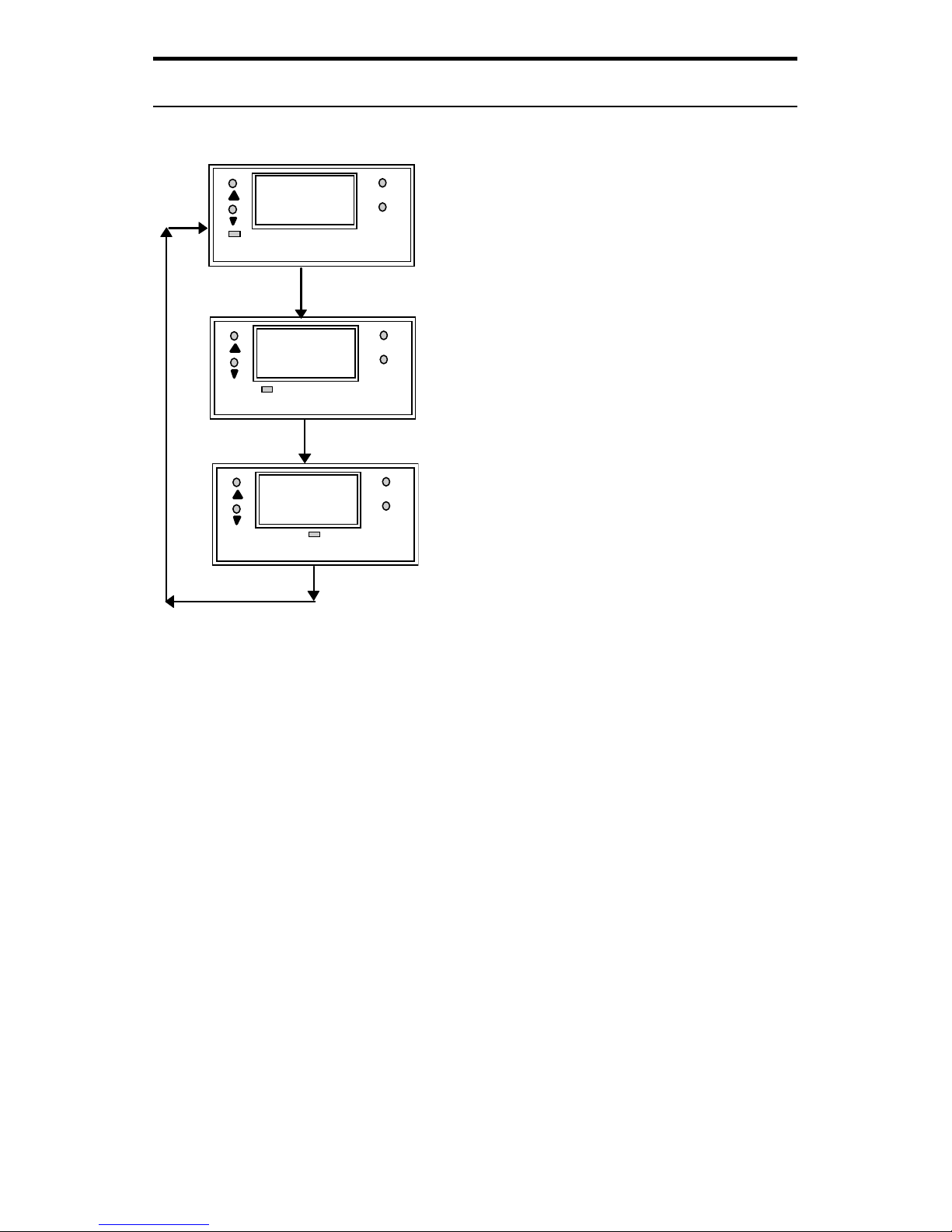
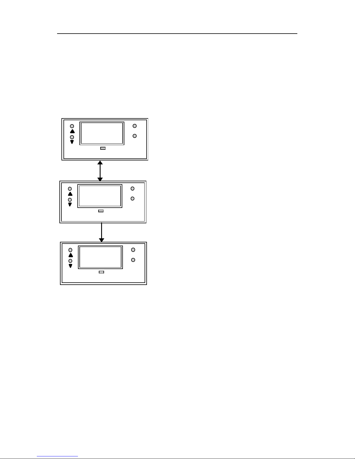
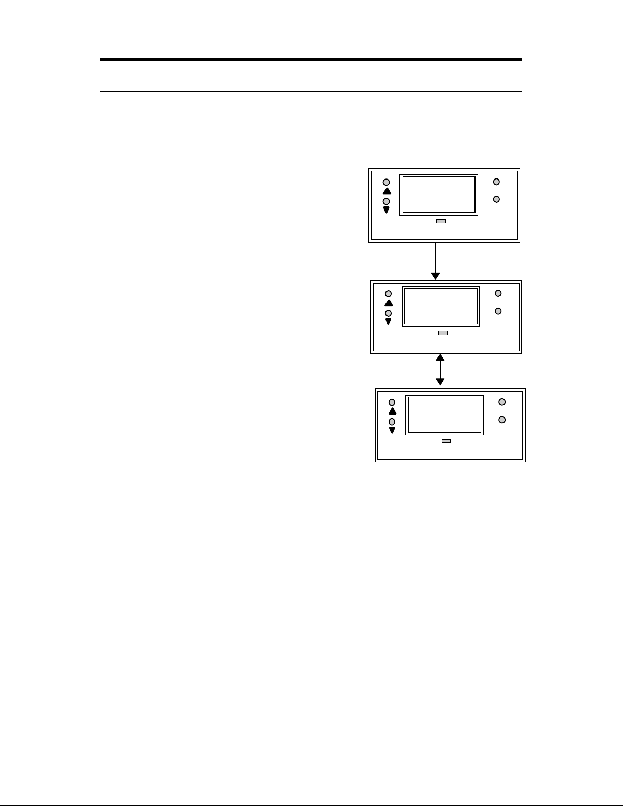
3. Operating the Controller
The Main Display
Press MODE key to switch to three
main displays - the Conductivity
display, the temperature display
and “SEt” display.
Press MODE key once to get into
the temperature measurement.
The °C annunciator lights up when
you are measuring temperature.
The display shows current
measured temperature (with ATC)
or the temperature that was set in
MTC mode. Press MODE key
again and the display toggles to
the “SEt” for SETUP menu.
Press ENTER key to go into the lower-level setup menus while
the display shows "SEt". These lower-level menus allow
calibration of Conductivity, Temperature and other parameters
including set password, Hi or Lo Setpoints, Hi and Lo Hysteresis
values and temperature coefficient.
uS/mS
MODE
ENTE
R
7.4
o
C
MODE
ENTE
R
24.0
SETUP
MODE
ENTE
R
SEt
Page 10
7
4. Setting Up the Controller
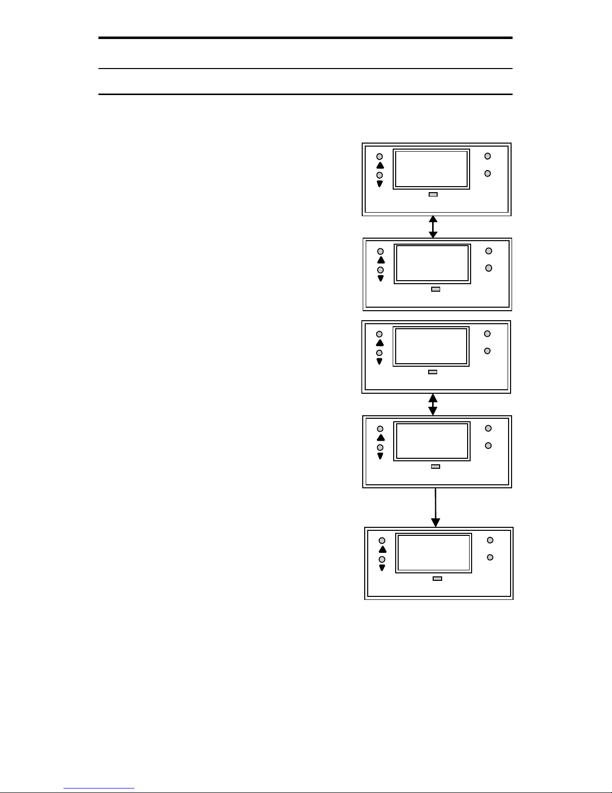
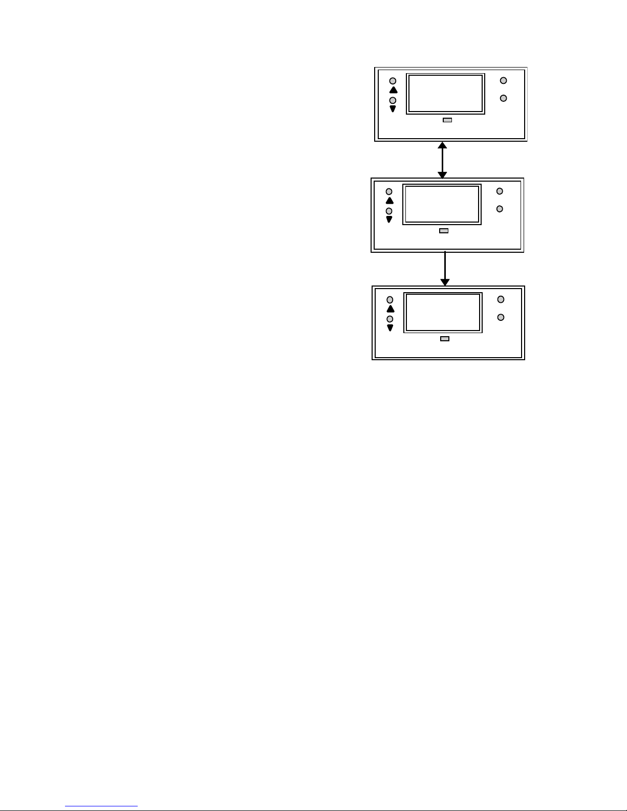
4.1 Setting and Changing the Password
4.1.1 Setting New Password
To set a password, press MODE key
until the “SEt” is displayed.
1. Press ENTER key and the
display shows "CAL” and “Con”
alternately. Press ▲ key once
and the display shows “Set”
“id”.
2. Press ENTER to enter your
desired password. Follow the
steps below (e.g. using a
password “123”).
3. Initially, the display shows "000"
with the first digit blinking.
4. Use ▲ (UP/INCREMENT) key to
enter “1” on the 1st digit of the
password. Press ENTER once
and the second digit will blink.
Similarly, enter the second digit
of the password “2” and press
ENTER key again. Repeat with
the third digit accordingly.
5. Press ENTER key and the
display shows “CAL” and ”COn”
alternately. Use ▲ or ▼ key to
get into the “SEt” and “id” menu,
press ENTER and set your
desired password by following
the above steps.
6. Once completed, press ENTER to confirm and then press
MODE key to return to the Conductivity display.
SETUP
MODE
ENTE
R
CAL
SETUP
MODE
ENTE
R
Con
SETUP
MODE
ENTE
R
SEt
SETUP
MODE
ENTE
R
id
SETUP
MODE
ENTE
R
123
Page 11

8
To calibrate the controller at any time, you may have to enter
the password that you set, in order to access the calibration
mode. Once you have entered the password correctly, the
display shows "CAL COn” indicating that you are in one of the
lower-level SETUP menus.
If you enter the wrong password, the display reverts back to the
Conductivity display. Alternatively, if you prefer no password
protection, set the password to “000”, "CAL COn" immediately
displays after you press ENTER key while you are in the "SEt"
menu.
NOTE : The user set password is a protection code. Thus, it is
very important to keep this password strictly confidential to
authorized personnel. You are advised to remember the
password that you have set, in order to protect the controller
settings and prevent any unauthorized tampering to the system!
IMPORTANT : In case the password set is forgotten, use
the master password “555”.
4.1.2 Changing the Password
Enter the Set id menu with already set password or “555”.
Change a new password as per steps mentioned for setting the
password.
Page 12

9
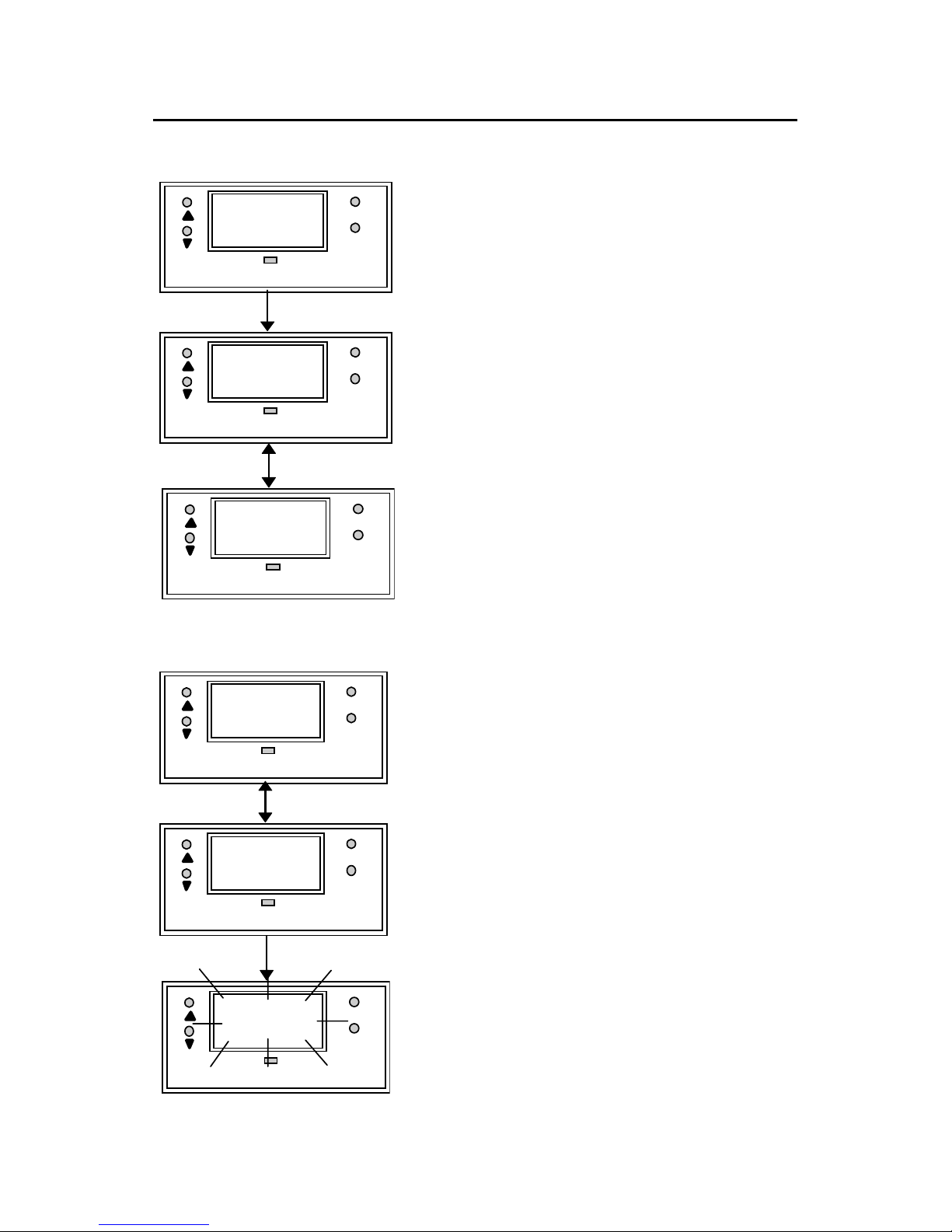
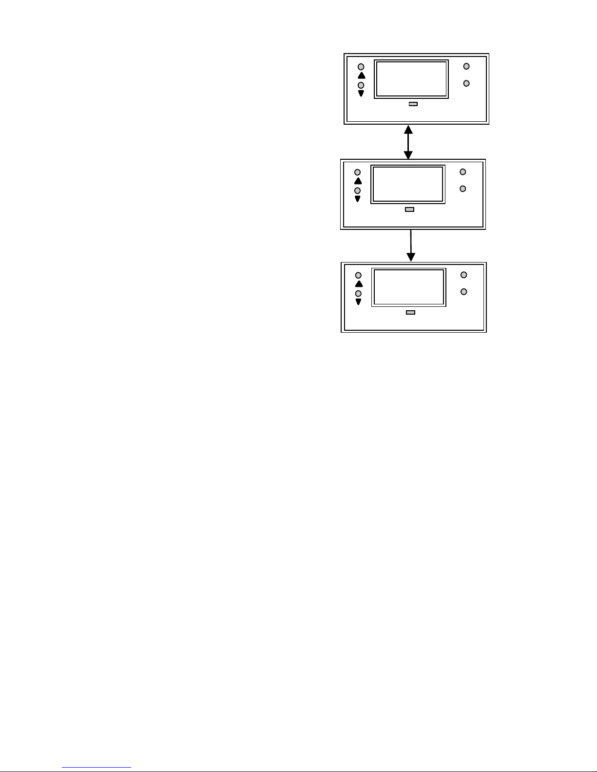
4.2 Setting the Controller Range (Software)
At the measurement mode, press
both ▲ and ▼ keys simultaneously
until the “CLr” display shows. Press ▲
or ▼ key to select the appropriate
Conductivity measurement range.
Press ENTER key to confirm.
Value scrolls from uS to mS, indicating
the measurement range or
uS/mS
MODE
ENTE
R
CLr
uS/mS
MODE
ENTE
R
999
uS/mS
MODE
ENTE
R
1.0
uS/mS
MODE
ENTE
R
uS
uS/mS
MODE
ENTE
R
100
Cell Constant either 0.1 or 1.0 blinks
when the 999 uS range is selected
uS/mS
MODE
ENTE
R
nnS
uS/mS
MODE
ENTE
R
100
Page 13

10
5. Calibrating the Controller
5.1 The Lower Level Menus
The "CAL COn" display is the first menu seen upon entering the
lower-level menus. Press ▲ or ▼ key to display the various
menus as shown in the figure below. Press ENTER key to go to
the lower level menus.
5.2 Calibrating for Conductivity Measurement
5.2.1 The CAL COn menu
1. Enter this menu by pressing the MODE key twice to the
“SEt” display from the measurement mode.
2. Press ENTER key. If the password has been set earlier,
key in the password using the method described in section
4.1. Press ENTER once to confirm. After you set the
correct password, you can see the “CAL” and “COn”
display blink alternately.
3. Press ENTER key to enter the Conductivity calibration
mode. Dip both the Conductivity electrode and temperature
probe in the standard solution
4. NOTE: The Conductivity standard solution should have
a conductivity value between 40% to 100% of its full
scale range selected
START
CAL COn
CAL oC
Hi
SEt
Hys
Hi
Lo
SEt
Hys
Lo
SEt tC
Set
id
Page 14

11
5. When “CAL COn” displays, press ENTER key to view the
default cell constant at 100%.
Press ENTER key again to show
the measured conductivity value.
Use ▲ and ▼ keys to scroll to
the standard’s Conductivity value
at 25
o
C.
6. Press ENTER key to calibrate
the Conductivity value shown.
Display will show the new cell
constant being displayed. This
value will be between 70% to
130%. Otherwise an error
message “CAL“ and “Err“
alternatively blinks to indicate
out of calibration range.
7. Press ENTER key to complete
the calibration, and you will
return to “CAL” and “COn”
menu.
8. Press MODE key and it brings
you to the Measure mode.
NOTE : Gently stir the electrode in
a container filled with calibrating
standard, and ENSURE that no
bubble is trapped during the
calibration process to avoid
erroneous reading.
IMPORTANT : The correct
Temperature Coefficient should be
selected prior to Conductivity
calibration. (Refer to Section 5.5 for
Setting Temperature Coefficient).
SETUP
MO
D
ENT
E
CAL
SETUP
MO
D
ENT
E
COn
SETUP
M
O
E
N
100
SETUP
MO
D
EN
T
CEL
SETUP
M
O
E
N
CEL
SETUP
M
O
E
N
99
Page 15
12
5.3 Calibrating the Controller for Temperature
Measurement
5.3.1 The CAL °C menu
1. Enter this menu by pressing
MODE key twice to the “SEt”
display if you are in
measurement mode.
2. Press ENTER key. If the
password has been set earlier,
key in the password using the
method described in section 4.1.
Press ENTER once to confirm.
After you set the correct
password, you see the “CAL”
and “COn” display blinks
alternatively. Press ▼ key once,
the display shows “CAL” “
o
C”
blinking.
1. Press ENTER and the display
alternatively shows “Atc” and “On” or “Atc” and “OFF”.
Use ▲ and ▼ keys to choose between both ATC ON and
ATC OFF.
ATC ON : If a PT 100 is connected,
use ▲ and ▼ keys to adjust the
temperature offset of the PT 100 by ±
5 °C. Dip the probe into the sample
liquid. Make sure that the display is
set to ATC ON, press ENTER and the
display now shows the actual
temperature reading (blinking).
Use ▲ and ▼ keys to adjust the
reading to its actual temperature - as
measured by an external
thermometer. Once done, press
ENTER key and the display will flash
“CAL” “Con” alternatively.
SETUP
MODE
ENTE
R
SEt
SETUP
MODE
ENTE
R
CAL
SETUP
MODE
ENTE
R
o
C
SETUP
MODE
ENTE
R
A
tc
SETUP
MODE
ENTE
R
On
SETUP
MODE
ENTE
R
23.5
Page 16
13
ATC OFF : If a PT 100 is not used,
then the ATC should be set to OFF.
In step 3 above, choose by pressing
▲ and ▼ keys to select ATC OFF.
Then press ENTER. The display
will now show the default of 25
o
C or
the last set value (blinking). Use ▲
and ▼ keys to set your desired
value. Press ENTER to confirm and
the display shows “CAL” “Con”.
Note : For ATC OFF, you can adjust
the set temperature values from 0.0
to 99.9
o
C. This value will be used
for its temperature compensation
e.g. Conductivity in the MTC mode.
SETUP
MODE
ENTE
R
A
tc
SETUP
MODE
ENTE
R
OFF
SETUP
MODE
ENTE
R
25.0
Page 17
14
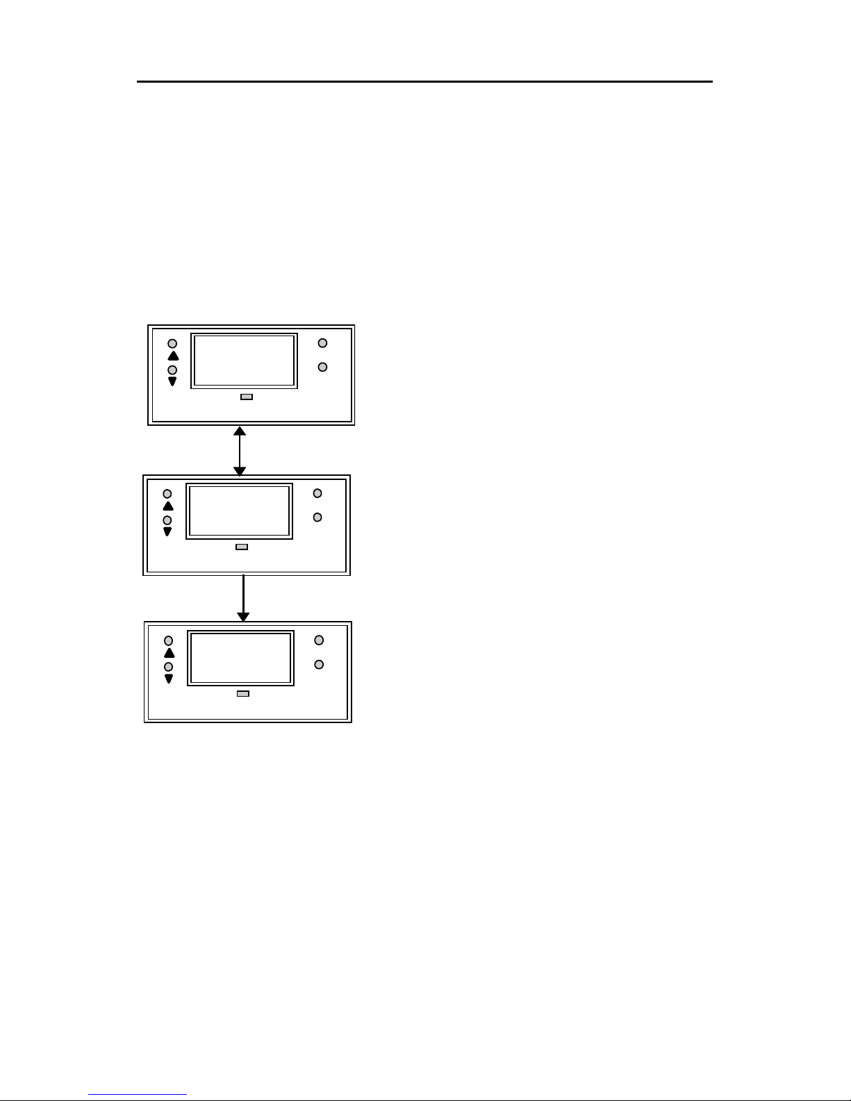
5.4 Setting the Alarm Feature
This menu allows you to change the Hi and Lo Setpoint and
Hysteresis values. See Section 8 for hysteresis applications.
IMPORTANT : When SETUP mode is entered, the 4-20 mA
output (only for transmitter model) freezes and the relay deactivates (if it was in an alarm condition).
5.4.1 The Hi SET Menu
1. Enter this menu by pressing
MODE key twice to the “SEt”
display if you are in
measurement mode.
2. Press ENTER key. If the
password has been set earlier,
key in the password using the
method described in section
4.1. Press ENTER once to
confirm.
3. After you set the correct
password, you see the “CAL”
and “COn” display blinks
alternately. Press ▼ key twice,
the display shows “Hi” “SEt”
blinking alternately.
4. Press ENTER key to access the Hi SET menu and the
display shows the last Hi SET value or default (90% of Full
Scale). Use ▲ and ▼ keys to change the value of the Hi
SET point.
5. Press ENTER to confirm the value of the Hi SET point.
6. Press MODE key to exit to the measurement mode. You
can press MODE key (as an ESCAPE key) to revert to the
measurement value if ENTER is not pressed; the set value
is not stored into memory.
SETUP
MODE
ENTE
R
Hi
SETUP
MODE
ENTE
R
900
SETUP
MODE
ENTE
R
SEt
Page 18
15
5.4.2 The Hi HYS Menu
1. Enter this menu by pressing the
MODE key to the “SEt” display if
you are in the measurement
mode.
2. Press ENTER key. If the
password has been set earlier,
key in the password using the
method described in section 4.1.
Press ENTER once to confirm.
After you set the correct
password, you see the “CAL”
and “COn” display blinks
alternatively. Press ▼ key thrice,
the display shows “Hi” “HYS”
blinking.
3. Press ENTER key to access the
Hi HYS menu and the display
shows the last Hi HYS value or
default (2% of Full Scale). Use ▲
and ▼ keys to change the value
of the Hi HYS point.
4. Press ENTER to confirm the
value of the Hi HYS.
5. Press MODE key to exit to
measurement mode. You can
press MODE key (as an
ESCAPE key) to revert to the
measurement value if ENTER is
not pressed; the set value is not
stored into memory.
SETUP
MODE
ENTE
R
Hi
SETUP
MODE
ENTE
R
02
SETUP
MODE
ENTE
R
HYS
NOTE : The maximum
value of Hysteresis is
4% of its Full Scale
(FS) selected. The HI
HYS hysteresis is
spread equally on
either side of the Hi
SET point.
Page 19

16
5.4.3 The Lo SEt Menu
1. Enter this menu by pressing
MODE key twice to the “SEt”
display if you are in
measurement mode.
2. Press ENTER key. If the
password has been set
earlier, key in the password
using the method described in
section 4.1. Press ENTER
once to confirm.
3. After you set the correct
password, you see the “CAL”
and “COn” display blinks
alternately. Press
▼ key four
times, the display shows “Lo”
“SEt” blinking alternately.
4. Press ENTER key to access the Lo SET menu and the
display shows the last Lo
SET value or default (5% of
Full Scale). Use
▲ and ▼
keys to change the value of
the Lo SET point.
5. Press ENTER to confirm the
value of the Lo SET point.
6. Press MODE key to exit to
measurement mode. You can
press MODE key (as an
ESCAPE key) to revert to the
measurement value if
ENTER is not pressed; the
set value is not stored into
memory.
SETUP
MODE
ENTE
R
Lo
SETUP
MODE
ENTE
R
50
SETUP
MODE
ENTE
R
SEt
NOTE : The Lo SEt
relay activates if the
current Conductivity
reading exceeds Lo
SET point - ½ Lo HYS
value. The Lo SET
value cannot be higher
than the Hi SET value.
Page 20
17
5.4.4 The Lo HYS Menu
1. Enter this menu by pressing
the MODE key to the “SEt”
display if you are in the
measurement mode.
2. Press ENTER key. If the
password has been set
earlier, key in the password
using the method described
in section 4.1.
3. Press ENTER once to
confirm. After you set the
correct password, you see
the “CAL” and “COn”
display blinks alternatively.
Press
▼ key five times, the
display shows “Lo” “HYS”
blinking alternately.
4. Press ENTER key to access
the Lo HYS menu and the
display shows the last Lo
HYS value or default (2% of
Full Scale). Use
▲ and ▼
keys to change the value of
the Lo HYS point.
5. Press ENTER to confirm the value of the Lo HYS.
Press MODE key to exit to the measurement mode.
You can press MODE key (as an ESCAPE key) to
revert to the measurement value if ENTER is not
pressed; the set value is not stored into memory.
IMPORTANT : The Lo SET + ½ Lo HYS should be less
than Hi SET - ½ Hi HYS i.e. Hi SET and Lo SET value (in
consideration of the hysteresis band) can never overlap. Lo
HYS and Hi HYS can be set independent of each other; this
allows non-symmetrical hysteresis option.
NOTE : The maximum
value of Hysteresis is
4% of its Full Scale (FS)
selected. The Lo HYS
hysteresis is spread
equally on either side of
the Lo SET point.
SETUP
MODE
ENTE
R
Lo
SETUP
MODE
ENTE
R
02
SETUP
MODE
ENTE
R
HYS
Page 21
18
5.5 Setting Temperature Coefficient
5.5.1 Temperature Coefficient
This menu allows you to set the Temperature Coefficient
corresponding to the solution whose Conductivity is being
measured. In most controllers, this is fixed at 2.10% per
o
C.
However, for alpha CON 100 C/CX models, it is adjustable
from 0.0 to 10.0% per
o
C (please refer to Appendix 3 for
Temperature Coefficient determination and limits).
1. Enter this menu by pressing
the MODE key to the “SEt”
display if you are in the
measurement mode.
2. Press ENTER key to access
the SETUP menu. Press
▲
key twice to enter the “SEt tc”
menu. If you do not wish to
effect any change and keep
the Temperature
Compensation as the previous
value, press MODE key. This
will take you out of this mode
and back to its measurement
mode.
3. Press ENTER and the display
shows the current value of
Temperature Coefficient (blinking).
4. Use
▲ or ▼ key to change the value of the
Temperature Coefficient. Press ENTER to confirm the
value to be used. Press MODE key to exit to
measurement mode.
SETUP
MODE
ENTE
R
tc
SETUP
MODE
ENTE
R
2.10
SETUP
MODE
ENTE
R
SEt
Page 22
19
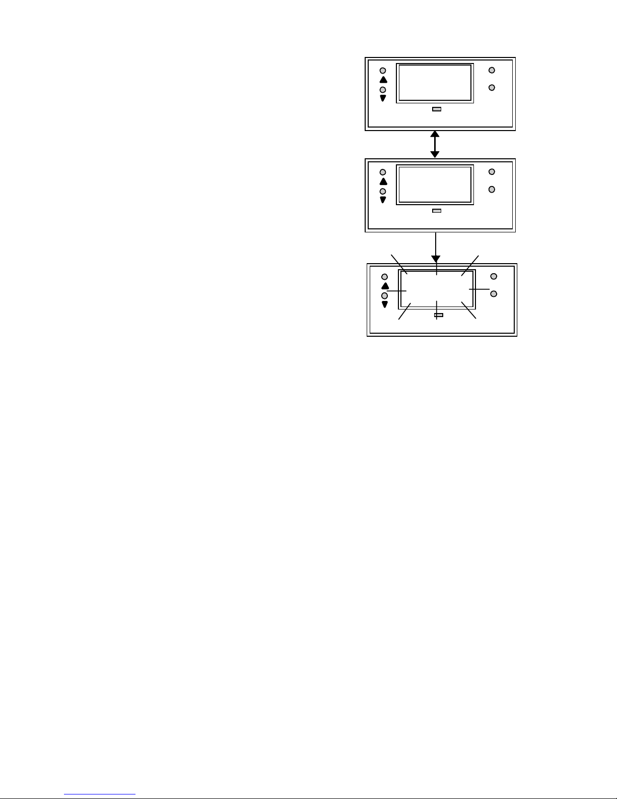
6. Setting to Factory Default
All the controller settings and user-defined password, except
calibration data will be cleared when you enter into the “Usr”
“Clr” menu.
Press both the ▲ and ▼ keys
simultaneously while you are in any
mode menu. The unit requests for the
password if it was set previously.
Enter the password and press
ENTER. The display will show “CLr”.
Press ENTER to confirm. The display
will blink briefly - the password is
reset to its factory default and toggles
to its measurement mode.
The Master Password is “555” and
default user set password is “000”.
The Master Password can be used
even if any other password was set
previously.
Key the master password “555” after entering into the “Ënt”
“id” display, you will see “Usr” and “Clr” display alternately.
Press ENTER to confirm and the display returns to its
measurement mode.
SETUP
MODE
ENTE
R
Ent
SETUP
MODE
ENTE
R
id
SETUP
MODE
ENTE
R
CLr
Page 23

20
7. Using the Controller Current Loop
for Datalogging (for Transmitter
Model Only)
The 4-20 mA Current Loop
A 4-20 mA current loop can be connected if a remote data
logging is required. The current will be proportional to the
Conductivity displayed on the panel display. The 4-20 mA
current loop can drive a load resistance of no more than 200Ω.
If the calculated Conductivity is less than 0 uS (due to incorrect
TC and temperature setting), the current will be set to
approximately 0 mA. If Conductivity exceeds the value that can
be measured in the range, current will be set to approximately
21 mA. In this way, the remote data logger can detect when out
of range conditions arise. Please note that the 4-20 mA loop is
not galvanically isolated from the source.
Page 24
21
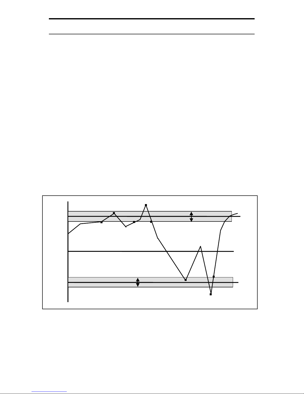
8. Additional Information
The controller allows you to set High and Low alarms that
switch on or off relays, and activating or deactivating devices
linked to the controller. In cases where the Conductivity values
fluctuate close to the high or low setpoints, the relays will
continuously switch on/off very quickly and may cause problems
to the linked devices. The hysteresis band allows you to set an
allowable range of fluctuations to prevent the relays from
activating and deactivating too quickly. See below.
It is not possible to set the high set point lower than the low set
point and vice versa (taking the hysteresis band into
consideration). For example, when the high set point is 8.50
mS and the high hysteresis band is set at 0.40 mS, then the low
setpoint cannot be set at higher than 8.50 - ½ Hi HYS.
NOTE : The shaded area indicates the hysteresis band.
Hi
Hy
Lo
Hys
Hysteresis Band
Hysteresis Band
Hi
Set
Lo
Set
Cond.
Actual
A
B
C
D
E
F
G
H
Page 25

22
Explanation of the diagram in the previous page
A - Reading reaches (Hi SET - ½ HI HYS), the Hi-Set relay
remains inactivated.
B - Reading reaches above High Setpoint but below (Hi SET +
½ Hi HYS), Hi-Set relay remains inactivated.
C - Reading reaches between (Hi SET - ½ Hi HYS), the Hi-Set
relay remains inactivated.
D - Reading reaches above (Hi SET + ½ Hi HYS), and the Hi-
Set relay is activated.
E - The Hi-Set relay is inactivated only when the reading falls
below (Hi SET - ½ Hi HYS).
F - Reading reaches between (Lo SET - ½ Lo HYS), the Lo-Set
relay remains inactivated.
G - Reading reaches below (Lo SET - ½ Lo HYS), the Lo-Set
relay is activated.
H - The Lo-Set relay remains activated until the reading goes
above the (Lo SET + ½ Lo HYS)
F
Page 26

23
Appendix 1
Jumper Positions - Internal to the Controller
JP1 Selects the input voltage between 110 VAC or
220 VAC.
Fuse Note that there is a fuse internal to the
Controller. Before opening the unit, ENSURE
that the power cable is physically separated
from the mains supply. Replace the fuse with
the one recommended by the manufacturer.
Front
Back
JP 1
Fuse
2
LED
Display
220VAC
Page 27

24
Appendix 2
Temperature Coefficient
The Temperature Coefficients (TC) of most solutions vary
between 1.8 to 2.4 % per
o
C. This is true of most salt solutions
when the Conductivity exceeds about 100 uS. Thus, the default
value of TC will be set to 2.10 % per
o
C when the Controller is
shipped from the factory. However, if the Temperature
Coefficient is known to be different from the default, the user
can set this value.
Temperature Coefficient can also be determined by taking 2
uncompensated readings at known temperatures.
Uncompensated readings can be taken by setting TC to 0.0 %
or setting the temperature to 25
o
C by changing ATC ON to ATC
OFF.
If G1 and G2 are the conductivity measured at two
temperatures T1 and T2, then TC is given by the relation:
% TC = ----------------------------------------
G1
(
T2 - 25) - G2(T1-25
)
G2 - G1
* 100
Page 28

25
Technical Specifications
Specifications Range Resolution Cell
Constant
Conductivity Range 0 - 99.9 uS
0 - 999 uS
0 - 999 uS
0 - 9.99 mS
0 - 99.9 mS
0 - 200 mS
0 - 200 mS
0.1 uS
1 uS
1 uS
0.01 mS
0.1 mS
1 mS
1 mS
0.1
0.1
1.0
1.0
1.0
1.0
10.0
Relative Accuracy +/- 1% full scale
Cell Constant 0.1, 1.0 or 10.0
Measurement Range 7 separate ranges (software selectable,
non auto-ranging)
Calibration Push-button (cell constant correction
function)
Temperature
Coefficient
0.0 to 10.0 % from 5 to 50 oC
Temperature
Compensation
Automatic / Manual (0 to 100.0 oC)
Temperature 0 to 100 oC
Resolution
0.1
o
C
Relative Accuracy
+/- 0.5
o
C
Sensor
PT 100
Output 4-20 mA, screw terminals (non-isolated);
Max. load 200 Ω
Display LED, 3 digits
Inputs screw terminals
Recommended Input
Cable Length
Less than 5 meters
Relays
No. Of Relays
Maximum Voltage
Maximum Current
High Hys. Band
Low Hys. Band
2 - High set & Low set SPDT
240 VAC
3A
4% of Full Scale Reading
4% of Full Scale Reading
Power Requirements 110 VAC or 220 VAC (Jumper selectable)
Environmental
Requirements
Operating
Storage
Humidity Limits
0 to 50
o
C
-10 to 60
o
C
10 to 95% RH (non condensing)
Storage Temp. Range 0 to 50 oC
Dimensions 1/8 DIN size; 96 (L) x 48 (H) mm (Front
panel)
Page 29

26
NOTES
Page 30

Page 31

For more information on Eutech Instruments products, contact your nearest Eutech
Instruments distributor or visit our website listed below:
Manufactured by:
Eutech Instruments Pte Ltd.
Blk 55, Ayer Rajah Crescent,
#04-14/24 Singapore 139949
Tel: (65) 778 6876 Fax: (65) 773 0863
E-mail: marketing@eutechinst.com
Website: http://www.eutechinst.com
Distributed by:
 Loading...