

EUTECH INSTRUMENTS ALPHA CON 1000 CONDUCTIVITY CONTROLLERTRANSMITTER, Alpha-CON1000 Instruction Manual
68X216802
Instruction Manual
αlpha-CON1000
Conductivity Controller/Transmitter
MEAS
8.088.08
mS
25.025.0
o
C
ATC
Conductivity Controller
ααlpha CON1000
CAL
ENTER
ALARM
REL A
REL B
AUTO
MANU
REL A
REL B
ESC

68X216802
2
Preface
This manual serves to explain the use of the αlpha-CON1000 series Conductivity
controller/transmitter. The manual functions in two ways: firstly as a step by step guide to help the
user operate the instrument. Secondly, it serves as a handy reference guide. This instruction
manual is written to cover as many anticipated applications of the αlpha-CON1000 Conductivity
controller/transmitter. If you have doubts in the use of the instrument, please do not hesitate to
contact the nearest Eutech Instruments’ Authorised Distributor.
The information presented in this manual is subject to change without notice as improvements are
made, and does not represent a commitment on part of Eutech Instruments Pte Ltd.
Eutech Instruments cannot accept any responsibility for damage or malfunction of the unit due to
improper use of the instrument.
Copyright 1998 Eutech Instruments Pte Ltd. Version 1.0. All rights reserved.
EUTECH INSTRUMENTS PTE LTD
Blk 55 Ayer Rajah Crescent, #04-16/24, Singapore 139 949. Tel: (65) 778 6876; Fax: (65) 773 0836
e-mail: marketing@eutechinst.com ; Website: http://www.eutechinst.com
TABLE OF CONTENTS
1 Introduction........................................................................................................3
1.1 Description of Unit.................................................................................3
1.2 Applications...........................................................................................4
2 Assembly and Installation...................................................................................5
2.1 Measurement and Control System...........................................................5
2.2 Unit Dimensions.....................................................................................5
3 Electrical Connection.........................................................................................6
3.1 Connection Diagram...............................................................................6
3.2 Back Panel .............................................................................................7
4 Overview.........................................................................................................8
4.1 Keypad and Display................................................................................8
4.2 Function Groups.....................................................................................9
4.3 Control Concept ................................................................................... 10
5 MEASUREMENT............................................................................................11
5.1 Display in Measurement mode..............................................................11
5.2 Security Codes...................................................................................... 11
6 Calibration Mode............................................................................................. 14
6.1 Conductivity Calibration.......................................................................14
7 ADVANCED SET-UP MODE.............................................................................15
7.1 Temperature Coefficient sub-function...................................................15
7.2 Temperature calibration (ATC mode only)............................................16
7.3 Control Relay A/Control Relay B (SP1/SP2) sub-function.....................17

Operating Instructions αlpha-CON1000
68X216802
3
7.4 Controller (Cntr) sub-function............................................................... 19
7.5 Measurement Range sub-function......................................................... 20
7.6 Current Output (rng) sub-function.........................................................21
7.7 Configuration (ConF) sub-function .......................................................22
7.8 Calibration (CAL) sub-function ............................................................23
8 Auto/Manual Mode..........................................................................................24
8.1 Auto mode (mode after switch-on)........................................................24
8.2 Manual mode........................................................................................ 24
9 Technical Specifications............................................................................... 25
10 Accessories Assembly Accessories....................................................................26
11 General Information......................................................................................... 26
11.1 Warranty .............................................................................................. 26
11.2 Packaging............................................................................................. 26
11.3 Return of Goods ................................................................................... 26
11.4 Guidelines for Returning Unit for Repair...............................................26
12 Appendices...............................................................................................27
12.1 Appendix 1 – Jumper Positions.............................................................27
12.2 Appendix 2 – Measurement Ranges available in the Controller..............28
12.3 Appendix 3 – Conductivity at Related Temperature Coefficients (25oC) 28
12.4 Appendix 4 – Conductivity of Various Aqueous Solutions at 25oC ........30
12.5 Appendix 5 - Simple Explanation on the Function of Hysteresis............ 31
12.6 Appendix 6 – General Instructions Concerning Controller Setting .........32
1 Introduction
1.1 Description of Unit
Thank you for purchasing Eutech’s ¼ DIN alpha-1000 series Conductivity process controllers. This
unit is used for measuring the Conductivity of a solution, either in micro-Siemens or milli-Siemens,
one at a time, and the operational mode is switchable from the menu. You can use this unit to
measure Conductivity with limit control. This controller has many user-friendly and safety features
which include:
• Menu-driven program that simplifies set-up
• Ten ranges of Conductivity measurements-software selectable (Appendix 2).
• Built-in memory backup to ensure that calibration data and other information are not erased
if power supply fails
• Automatic temperature compensation (ATC) with Pt100 or Pt 1000
• Manual temperature compensation with independent setting for calibration and process
temperature
• Temperature coefficient variable between 0.00 to 10.00 % per oC. Separate pure water
compensation curve stored in memory. Reference temperature at 25oC.
• 0 to 1999 second time delay adjustment on all relays – minimise false alarms
• Separately adjustable high and low set point hysteresis (dead bands) prevent chattering of
relays around the set points

68X216802
4
• Three control modes: limit, proportional pulse length or proportional pulse frequency
• Large dual display LCD for easy reading with clear multiple annunciators, alarm status and
operational message annunciators
• Two switching contacts as set-point triggering relays and an alarm output relay
• Separate alarm relay alerts you when set points have exceeded the limits and if the
Pt100/Pt1000 wires are broken or disconnected during the ATC function
• Hold function freezes output current (0/4...20mA) and releases control relays
• LED indicators signal control activities to monitor controller status from a distance
• Protection against electromagnetic interference - galvanically isolated 0/4..20mA output
provides safety for data logging and control purposes
1.2 Applications
Use this controller in panel mounted enclosures for applications in water treatment and
demineralization, waste water treatment and neutralization processes.
68X216802
2 Assembly and Installation
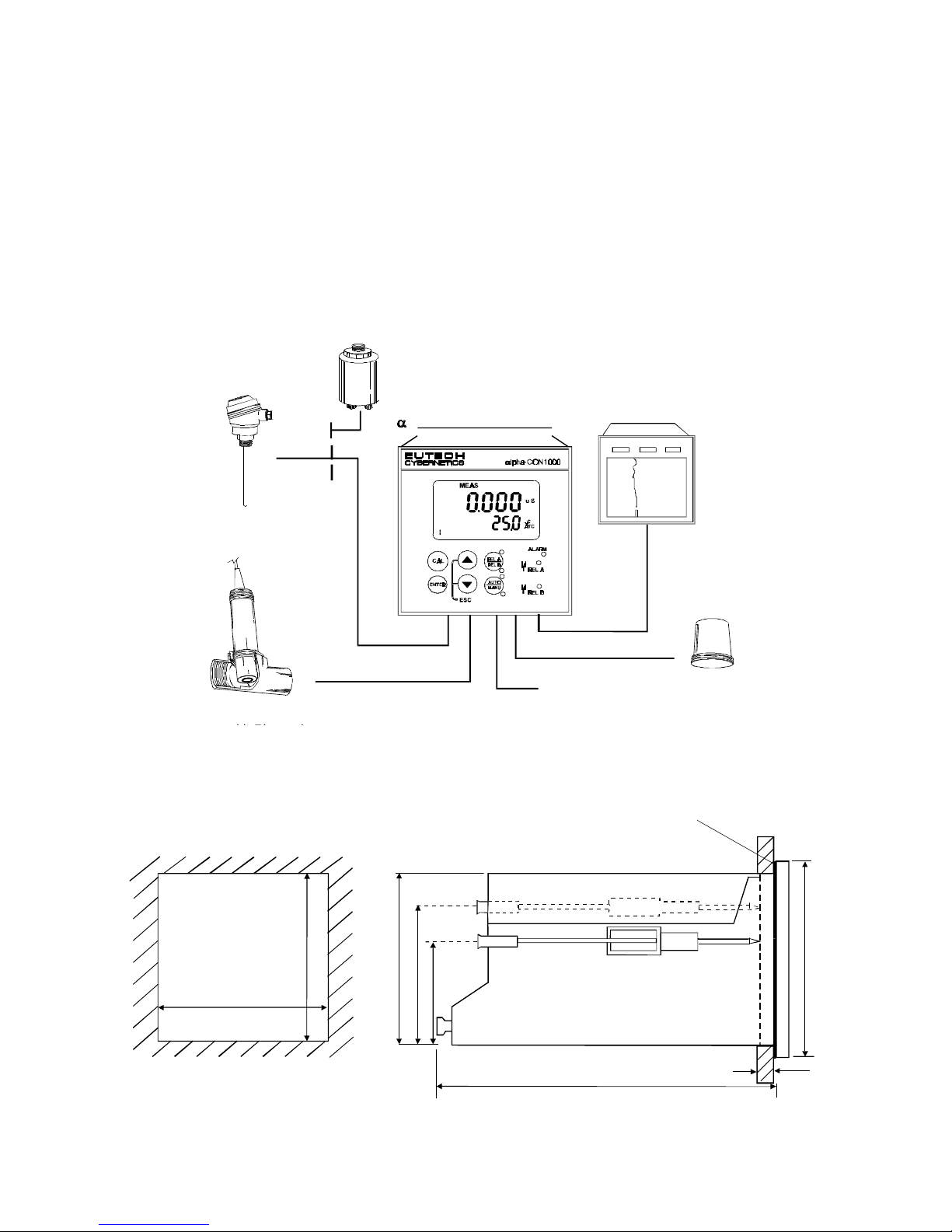
2.1 Measurement and Control System
A typical measurement system consists of:
• a αlpha-CON1000 process controller
• a suitable Conductivity electrode with the appropriate Cell constant and integrated temperature
sensor Pt 1000 or Pt 100,
• an immersion, flow or process assembly
• a final control element such as pump or valve and
• a chart recorder.
2.2 Unit Dimensions
PowerMain
s
(220/110VAC)l
FlowAssembl
y
toDosingPumpsProcessAssembl
y
ChartRecorder
Pt100/Pt100
0
TemperatureSensor
pha-CON1000Controller
Alarm/SirenSystem
max. 175
max. 45
Mounting Cut-Out
FlatGasket(1mm)
(To be Inserted By Customer)
Note: The Taped Corners Have to Be On Top
92
32
56
9
6
92 + 0.5
92 + 0.5
68X216802
6
The field-tested control panel housing is 96 x 96 mm; with protection class IP 54 (front).
Electrical Connection
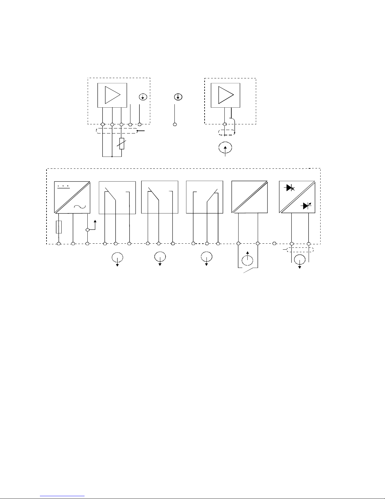
3.1 Connection Diagram
-
+
PE/S
PEAC: NL
1
2
5
4
3 6
7 8 9
10
11
12 13
14
151715 16
* ) indicated contact positions are for currentless conditions
Signal OutputHold Input
Alarm
Relay B
Relay A
Power Mains
CON
mA
Signal Input
Conductivity
S
/
V
PE/S
CON
O
O
18 19 20 21 22
S/S
/
Pt 1000/100
Operating Instructions αlpha-CON1000
68X216802
7
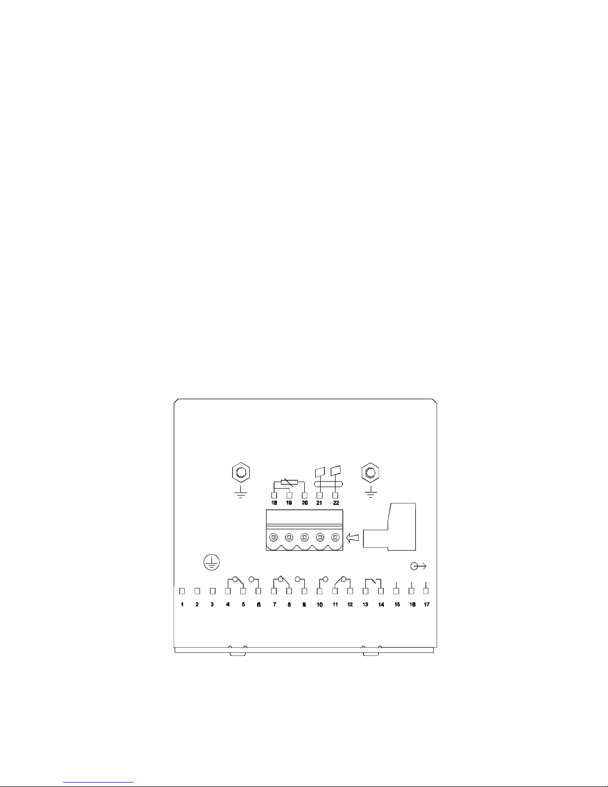
3.2 Back Panel
The back panel consists of two connectors. The first connector is the 17-way PCB edge connector and
the other is the 5-way connector.
Connection for the 17-way screw terminals (from left to right):
1. AC mains live wire 10. Alarm relay resting position (NO)
2. AC mains neutral wire 11. Alarm relay common
3. AC mains protective earth wire 12. Alarm relay working position (NC)
4. Low set relay resting position (NC) 13. Hold function switch terminal 1
5. Low set relay common 14. Hold function switch terminal 2
6. Low set relay working position (NO) 15. No connection
7. High set relay resting position (NC) 16. 0/4 - 20 mA for -ve connection
8. High set relay common 17. 0/4 - 20 mA for +ve connection
9. High set relay working position (NO)
Connections for the 5-way screw terminals:
18. Pt1000/Pt100 lead 1 terminal
19. Pt1000/Pt100 sense lead terminal
20. Pt1000/Pt100 lead 2 terminal
21. Conductivity lead 1
22. Conductivity lead 2
IMPORTANT: The Alarm relay functions as an “Active Low” device i.e. it switches OFF under
Alarm condition. Therefore the Alarm display device should be connected to the ‘NC’ contacts of
the relay.
Pt100/
RELAY1
L N PE
63mA
(F)
FUSE 250VAC
HOLD
ALARMRELAY2
Pt1000
NC
-
+
cell
J2
68X216802
4 Overview
4.1 Keypad and Display
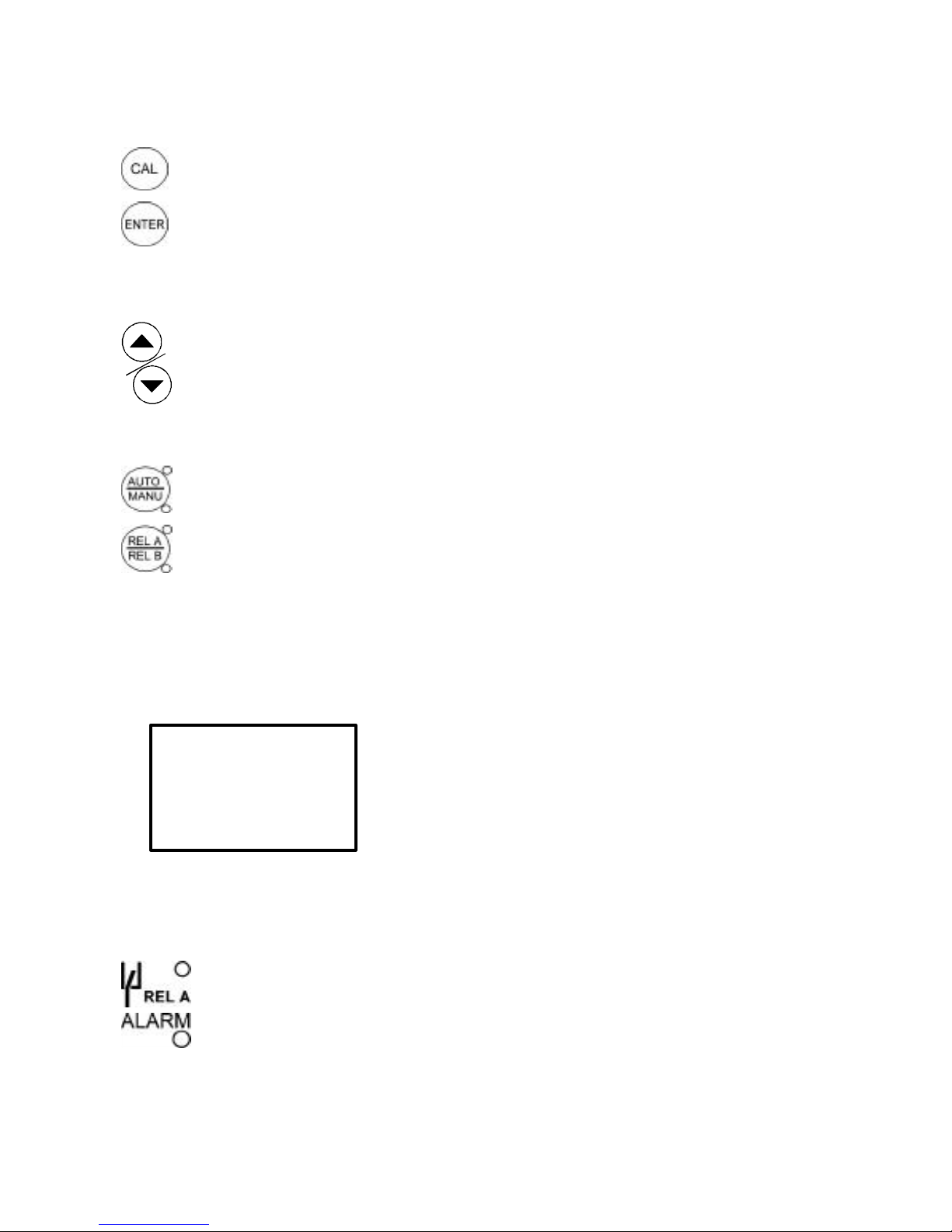
4.1.1 Keypad
• Perform rapid calibration
• Allows entry to Set up mode
• Select individual functions within the function group of Set up mode
• Store input data in the Set up mode
• Start calibration in the calibration mode
• Select various function groups in the Set up mode.
• Set parameters and numerical values in sub functions of Set up mode
If pressed continuously, the setting speed increases
• Control the relays in the MANUAL function
• Return to the Measurement mode when both keys are pressed together
• Switch between AUTO and MANUAL relay operation using a code
• Display limit set-point values for the switch contacts in AUTO relay operation mode
• Switch between RELAY A and RELAY B in MANUAL relay operation mode
4.1.2 Display
The LCD display features two numerical displays that show status messages and measured values for
easy, quick reference. The display provides short-text information for setting parameters and
configuration.
• HOLD: Relay position and current output are frozen
• SETUP: Set-up mode of function groups
• MEAS: Measurement mode
• CAL: Calibration mode of Conductivity
• READY: Comes on after a successful calibration
•
ATC: Comes on in the ATC mode. Disappears in the
Manual temperature Compensation mode. “ATC”
flashes if the temperature probe is faulty in its ATC
mode
•
Range No.: Indicates the measurement range
selected
• Display for RELAY A/B. Green LED indicates measured value within limit while
RED LED indicates measured value outside limit.
• Alarm display if limit value overshoot or the ATC connection is broken.
-8.8.8.8-8.8.8.8
HOLD SETUP MEAS CAL
READY
µµ
S
mS
o
C
88
Operating Instructions αlpha-CON1000
68X216802
9
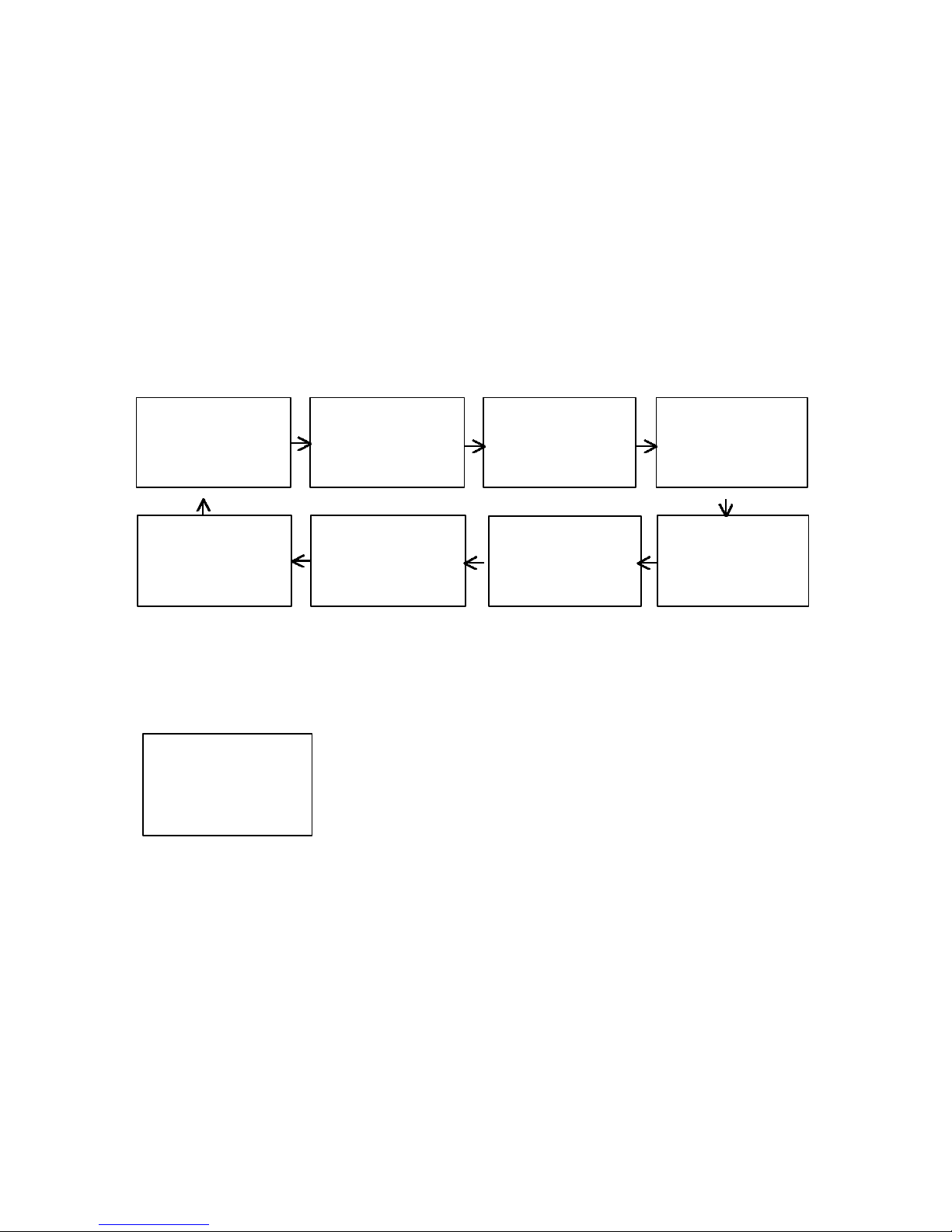
4.2 Function Groups
The main function and sub-function groups are organised in a matrix format for configuration and
selection of parameters. The main function groups are:
1) Temperature Coefficient settings (tCtC)
2) Temperature Measurement / compensation settings (SSEEt t
oo
CC)
3) Control relay 1 configuration (SP1SP1)
4) Control relay 2 configuration (SP2SP2)
5) Control type (CntrCntr)
6) Current output (rngrng)
7) Configuration (ConFConF)
8) Calibration (CAL CAL dOdO)
The set-up parameters can be viewed or changed by entering a security code. See Section 5.2 for
security code information.
4.2.1 How to view operating parameters without access to change them:
a) Press the ENTER key. The display will prompt the user to enter a
security code (S.Cd). Leave the security code at “000” (do not enter a
security code).
b) Press ENTER key again. This allows you only to view (not
change) any sub-functions’ settings.
c) Press the ∆∆ or ∇∇ keys to scroll through the sub-functions.
d) Press the ENTER key at a particular sub-function to view in detail.
e) Press the ENTER key to return to the sub-function menu.
f) Press the ∆∆ and ∇∇ keys simultaneously (as an Escape key) at any time to return to the
Measurement mode.
Note: To simplify operations, the controller will not display parameters that are not relevant to a
particular sub-function. For example: If the user set the controller for Limit control, it will not display
pulse length/frequency settings.
000000
tctc
HOLD SETUP
SEt
SEt
oo
CC
HOLD SETUP
SPSP 11
HOLD SETUP
SP2SP2
HOLD SETUP
ConFConF
HOLD SETUP
rngrng
HOLD SETUP
CntrCntr
HOLD SETUP
CALCAL
ConCon
HOLD SETUP
68X216802
10
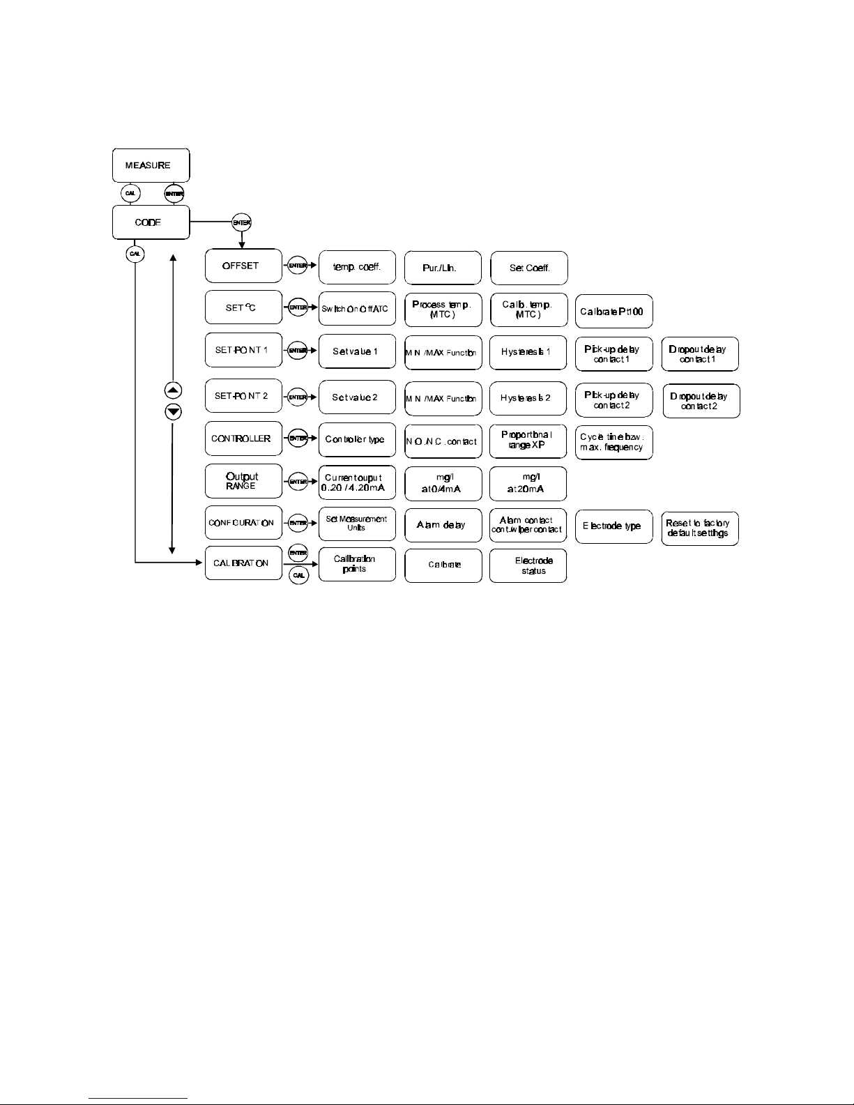
4.3 Control Concept
The main function and sub-function groups are organised in a matrix format as shown below. These
functions can be accessed via the front keypad for configuration and selection of parameters.
The controller offers two levels of password protection: (1) for direct access to calibration function and
(2) for setting or editing specific controller parameters or functions in the SETUP mode to suit individual
requirements.
Note: The passwords are not user-defined and have been set by factory. It is very important to keep
these passwords strictly confidential to avoid unauthorised tampering of the system at all times.
Note: If the user reads parameters only, the controller automatically reverts to Measurement mode if
none of the keys is pressed for 30 seconds.
 Loading...