

Page 1

Inductive
Read/Write Identsystem
CIS3A-Mini
System - Manual
for
Read/Write Head CIT3A...
Evaluation Unit CIA3...
Ident No. 084727
EUCHNER GmbH + Co.
P.O. Box 10 01 52
D-70745 Leinfelden-Echterdingen
Germany
Phone +49 / 711 / 75 97-0
Fax +49 / 711 / 75 33 16
www.euchner.com
info@euchner.de
Page 2

EUCHNER Identsystem CIS3A-Mini
Contents
1 Overview..................................................................................................................3
2 Connection and setup of the evaluation unit CIA3...................................................3
2.1 RS232-Interface:.........................................................................................................3
2.2 RS422-Interface:.........................................................................................................4
2.3 Notes on installation....................................................................................................4
2.4 Settings.......................................................................................................................4
2.4.1 DIP switch settings.................................................................................................4
2.4.2 Interface setting .....................................................................................................5
2.5 Connector pinout / LED functions................................................................................6
3 Basic telegram structure..........................................................................................7
3.1 Basic command structure............................................................................................7
3.2 Special features of the data transfer protocol 3964R [1].............................................8
3.2.1 Basic information on data transfer procedures with protocol [1].............................8
3.2.2 The transfer protocol 3964R [1].............................................................................8
3.2.2.1 Control sends [1]................................................................................................9
3.2.2.2 Control receives [1] ............................................................................................9
3.2.3 Summary of the most important points.................................................................10
4 Commands for reading and writing the read/write data carrier ..............................11
4.1 Write operation .........................................................................................................12
4.2 Read operation .........................................................................................................13
5 Commands for reading the data carrier read-only .................................................15
5.1 Read operation .........................................................................................................15
5.2 Example, how to read a data carrier read-only..........................................................17
6 Command overview...............................................................................................17
7 Status messages...................................................................................................18
8 Technical data of the evaluation unit CIA3SX........................................................19
9 Technical data of the read/write head CIT3...........................................................20
10 Parts list (overview) .............................................................................................21
Bibliography:..............................................................................................................22
084727-01-02/03 Subject to technical modification Page 2 / 22
Page 3

EUCHNER Identsystem CIS3A-Mini
S
1 Overview
This manual describes technical features and function of the evaluation unit with serial
interface cat. no. 077910 type CIA3SX1R1G08 and the communication with PC or SPS.
The transfer telegrams for the commands
- Program (write) data carrier
- Read data carrier
are based on the 3964R transfer procedure [1].
2 Connection and setup of the evaluation unit CIA3...
2.1 RS232-Interface:
CIA3SX...G08
PC or SP
9 - pin
25 - pin
084727-01-02/03 Subject to technical modification Page 3 / 22
Page 4

EUCHNER Identsystem CIS3A-Mini
2.2 RS422-Interface:
CIA3SX
A/TxD+
B/TxD-
0V
A1/RxD+
B1/RxD-
RxD+
RxD-
Signal Ground
TxD+
TxD-
PC or SPS
S2
2.3 Notes on installation
· Do not connect the evaluation unit CIA3... as well as the read/write head CIT3... as long
as power is on.
2.4 Settings
2.4.1 DIP switch settings
The settings of the DIP switches is only checked after the power-on cycle.
So it makes no sence to change the DIP switch setting during operation of the unit.
Changes are only valid after a power-off / power-on cycle.
S1 S2
1 2 3 4 5 6 7 8
084727-01-02/03 Subject to technical modification Page 4 / 22
Page 5

EUCHNER Identsystem CIS3A-Mini
Functions of the DIP switches
Switch Functions Default settings
1-1 (1) OFF=9600 Baud or ON=28800 Baud OFF 9600 Baud
1-2 (2) OFF
1-3 (3) OFF
1-4 (4) OFF
2-1 (5) OFF
2-2 (6) OFF
2-3 (7) OFF
2-4 (8) ON= Data carrier read-only
OFF= Data carrier read/write
General note:
All presently un-used switches must be set “OFF”. Thus, possible problems can be avoided with
functions which may be added in the future.
OFF Data carrier read/write
2.4.2 Interface setting
For the pre-setting of the interface type, the rotary switch "S3" is responsible.
Default setting is RS232
Switch position 1 Switch position 3
RS232 RS422
084727-01-02/03 Subject to technical modification Page 5 / 22
Page 6

EUCHNER Identsystem CIS3A-Mini
2.5 Connector pinout / LED functions
Type label / LED's:
H1 H2
H1 H2
24V 0V
24V 0V
CIS 3
CIS 3
CIS3
LED
LED
0V
0V
STATE
STATE
ACTIVE
ACTIVE
S1
SHS1
OUT
OUT
Read/write head connection
Power supply
STATE LED: Lights steady green, when the power is on.
ACTIVE LED: Lights steady yellow, when a functional data carrier is
in the active range of the read/write head.
S2S
RXD TXD 0V
RXD TXD 0V
B
B
A
A
SH
B1A1
B1A1
RS232-interface connectors
RS422-interface connectors
Connectors:
H1: Analog connection 1 to the read/write head cable-colour: brown
H2: Analog connection 2 to the read/write head cable-colour: white
LED: Data carrier active cable-colour: yellow
SH: Shield connection for the read/write head cable cable-colour: green + shield
24V: Power supply +24V
0V: Power supply 0V
0V: Output signal "data carrier active" (GND)
OUT: Output signal "data carrier active" (High +24V)
(Concurrent with "ACTIVE LED" yellow)
RxD: Receive data (RS232-Interface)
TxD: Transmit data (RS232-Interface)
0V: GND (RS232-Interface)
S2: Shield connection for the data cable
A: TxD+ (RS422-Interface)
B: TxD- (RS422-Interface)
A1: RxD+ (RS422-Interface)
B1: RxD- (RS422-Interface)
084727-01-02/03 Subject to technical modification Page 6 / 22
Page 7

EUCHNER Identsystem CIS3A-Mini
n
3 Basic telegram structure
Each command and any related data blocks are transferred within the telegram frame in
accordance with procedure 3964R from and to the ident system (figure 1).
With Protocol 3964R, the relevant receiver acknowledges the received telegram by
returning an acknowledgement character (DLE). In the case of negative acknowledgement
(NAK), the entire protocol is repeated. If it is not possible to transfer the protocol error-free
after a total of six attempts, the operation is aborted.
3.1 Basic command structure
Connection
set-up
Telegram data
max. 128 bytes
(telegram core)
Connection
cleardown
Figure 1: Basic command structure
Description Byte No. C o n t e n t s
ASCII
3964R procedure start
STX
Number of telegram bytes 0
Command
identification
Header address 301
User data description 4
1
2
T or R
command
hex
Start address
5
6
Start address
Number of
data items
User data 7
to n
3964R Procedure end DLE
ETX
BCC
Acknowledgeme
of the receiver
+ -
DLE NAK
DLE NAK
084727-01-02/03 Subject to technical modification Page 7 / 22
Page 8

EUCHNER Identsystem CIS3A-Mini
3.2 Special features of the data transfer protocol 3964R [1]
The 3964R data transfer protocol is a comparatively reliable program for electronic data
interchange between a control and a connected peripheral since data transfer is handled with
a standardised protocol.
On controls with integrated 3964R driver (see [1] for instance), it is not necessary for the
user to bother with the details of connection set-up and clear down respectively pay attention
to data integrity. It suffices to transfer the telegram core to the 3964R driver via the program.
On controls without 3964R driver or if a Electronic-Key-System is connected to a PC, the
user must, however, also program the connection set-up and clear down as well as the retry
attempts.
3.2.1 Basic information on data transfer procedures with protocol [1]
Numerous conventions must be agreed upon for a data transfer procedure: Codes, operating
modes, transfer speeds and the algorithmic transfer sequence. The stipulation of the
algorithmic sequence is referred to as transfer protocol (protocol for short). A transfer
protocol generally defines the following phases of data transfer:
· Connection establishment: Request from A to B for data transfer
· Data transfer from A to B
· Connection termination: End of data transfer
3.2.2 The transfer protocol 3964R [1]
Unlike non-protocol-based data transfer procedures, 3964R is a data transfer procedure with
protocol. This means that the actual data to be transferred is enclosed in specific control
characters. The 3964R driver allows comparatively reliable data transfer by virtue of the fact
that the receiver must first signal to the transmitter that it is ready to receive (connection setup) and, after data interchange, must acknowledge correct reception. Data integrity is
enhanced by an additional block check character with the 3964R transfer protocol.
The 3964R driver interprets the following control characters:
· DLE (10
· STX (02
· NAK (15
· ETX (03
) Data Link Escape
hex
) Start of Text
hex
) Negative AcKnowledgement
hex
) End of Text
hex
084727-01-02/03 Subject to technical modification Page 8 / 22
Page 9

EUCHNER Identsystem CIS3A-Mini
With the 3964R transfer protocol, a block check character (BCC for short) is transmitted
for data integrity at the end of each data block. The block check character BCC is the even
longitudinal parity (exoring of all data bytes) of a transmitted or received block.
Generation starts with the first user data byte (first byte of the telegram) after connection
set-up and ends after characters DLE and ETX on connection clear down.
3.2.2.1 Control sends [1]
The control sends the control character STX in order to set up the connection. If the
peripheral responds before expiry of the acknowledgement delay time (QVZ, typically: 2
seconds) with control character DLE, the control system switches to transmit mode. If the
peripheral responds with control character NAK or any other character (apart from DLE) or if
the acknowledgement delay time elapses with no response, this means that connection setup has failed. The procedure is aborted after a total of 6 unsuccessful attempts (specification
of the 3964R protocol). If connection set-up is successful, the user information characters
contained in the control's transmit buffer are transmitted to the peripheral at the selected
transfer speed. The peripheral monitors the interval between the incoming characters. The
interval between two characters may not exceed the character delay time (ZVZ, typically: 100
ms).
Each control character DLE (10
) contained in the user information must be transmitted
hex
twice so that the communication partner recognises that the data is user data and not the
control character DLE. (DLE doubling).
After transmission of the user data, the control appends the following characters as end
identifier: DLE, ETX, BCC
The control then waits for an acknowledgement character from the peripheral. If the
peripheral sends control character DLE within the acknowledgement delay time (QVZ,
typically: 2 seconds), the data block has been accepted error-free. By contrast, if the
peripheral responds with control character NAK or any other character or if the
acknowledgement delay time elapses with no response, the control starts transmission again
with connection set-up STX. The procedure is aborted and the control sends the control
character NAK to the peripheral after a total of 6 unsuccessful attempts (specification of the
3964R protocol).
If the peripheral sends control character NAK during a running transmission, the control
aborts the block and repeats it in the manner described above. In the case of any other
character, the control initially waits for the character delay time (ZVZ) to elapse and then
sends control character NAK in order to set the peripheral to idle state. The control then
starts transmission again with connection set up STX.
084727-01-02/03 Subject to technical modification Page 9 / 22
Page 10

EUCHNER Identsystem CIS3A-Mini
3.2.2.2 Control receives [1]
If the control receives control character STX from the peripheral in idle state, it responds with
DLE. If the control receives another character (apart from STX) in idle state, it waits for the
character delay type (ZVZ, typically: 100 ms) to elapse and then sends the control character
NAK. After each character, the next character is awaited during the character delay time
(ZVZ). If the character delay time elapses without reception, control character NAK is sent to
the peripheral.
If the control detects character string DLE ETX BCC, it terminates reception. It compares
the received block check character BCC with the internally generated longitudinal parity. If
the block check character is correct and no other reception error has occurred, the control
sends control character DLE. If the BCC is incorrect, control character NAK is sent to the
peripheral. A retry is then awaited. If it is not possible to receive the block error-free even
after a total of 6 attempts (specification of the 3964R protocol), or if the retry is not started by
the peripheral within the block waiting time of 4 seconds, the control aborts reception.
If transmission errors (lost character, frame error, parity error) occur during reception,
reception continues through to connection clear down and control character NAK is then sent
to the peripheral. A retry in the manner described above is then awaited.
3.2.3 Summary of the most important points
· DLE doubling:
In order for the control to be able to distinguish between control character DLE and any
randomly occurring DLE as user information character, a further DLE must be sent in
the case of a DLE as user information character. This means that if a byte with ASCII
value DLE ( 10
) occurs within the telegram core, this character must be transmitted
hex
again so that it is not interpreted by the distant station as a control character for
connection clear down.
· Block check character (BCC):
A block check character is sent at the end of each data block for data integrity. The block
check character BCC is the even longitudinal parity (exoring of all data bytes) of a
transmitted or received block. Generation starts with the first user data byte (first byte
of the telegram) after connection set-up and ends after characters DLE and ETX on
connection clear down.
· Retry attempts in the case of errors:
If an error occurs for any reason during data transfer, a total of 6 attempts are made in
order to transfer the data correctly.
084727-01-02/03 Subject to technical modification Page 10 / 22
Page 11

EUCHNER Identsystem CIS3A-Mini
4 Commands for reading and writing the read/write data carrier
Read and write operations are always initiated by the host control (PC, PLC) with a "command
telegram".
The Electronic-Key-System then sends a response telegram to the control.
Control Ident system CIS3...
Command telegram
¾¾¾¾¾¾¾¾®
Response telegram
¬¾¾¾¾¾¾¾
IMPORTANT !!!
Please note:
The memory of the read/write data carriers is organised in 4 byte blocks. So it
is only possible to write complete 4-byte blocks (if you want to write only 3
bytes, you have to fill the 4th byte with a filler byte). You also have to pay
attention to the start address: For the start address to write any data it is also
only possible to use byte 0, byte 4, byte 8, byte 12 and so on.
This restriction is only valid for writing data into the data carrier! For reading it
is possible to read every single byte on every address.
084727-01-02/03 Subject to technical modification Page 11 / 22
Page 12

EUCHNER Identsystem CIS3A-Mini
4.1 Write operation
The data carrier must be in front of the read/write head in case of this command and
may be removed from the active range only after reception of the response telegram.
Please note:
It is only possible to work with a maximum of 32 bytes of user data per command
telegram! If more data is required (max. 116 byte), it must be splitted to more than one
command telegram.
Command telegram (telegram core, PLC ® CIA3SX , see also figure 2):
TP (read/write head address) (start address) (number of bytes user data) (user data)
Response telegram (telegram core, CIA3SX ® PLC, see also figure 3):
RF (read/write head address) (0,0) (status no.)
Byte
No.
0
1
2
3
4
5
Description
ASCII
C o n t e n t s
hex decimal
Number of telegram bytes 0B ... 7B 11 ... 123
Command
identification
T
P
54
50
Read/write head address 01 1
Start address of the
user data
00
00 ... 70
Number of bytes of the
6
7 ... 122
Figure 2: Command telegram "write data carrier" (telegram core)
Byte
No.
0
1
2
3
4
5
6
user data 04 ... 20 4 ... 32
User data ASCII or hex resp. BCD (code-transparent)
Description
ASCII
C o n t e n t s
hex decimal
Number of telegram bytes 07 7
Command
identification
R
F
52
46
Read/write head address 01 1
Padding data 00
00
Status number **)
84
80
0
0 ... 112
82
70
0
0
Figure 3: Response telegram "write data carrier" (telegram core)
**) Status number 00
: No error
hex
02
: Data carrier not in active range
hex
(more status numbers see chapter 8)
084727-01-02/03 Subject to technical modification Page 12 / 22
Page 13

EUCHNER Identsystem CIS3A-Mini
4.2 Read operation
Command telegram (telegram core, PLC ® CIA3SX, see also figure 4):
TL (read/write head address) (start address) (number of bytes user data)
Response telegram (telegram core, CIA3SX ® PLC, see also figure 5 or figure 6):
There are two different possible responses for this command
1. RL (read/write head address) (start address) (number of bytes user data) (user data)
or
2. RF (read/write head address) (0,0) (status no.)
The response telegram RL (see also figure 5) means error-free reception of the data.
If it is not possible to read a data carrier, an RF response telegram is received
(see also figure 6). The status number then indicates the cause of the error.
Byte
No.
0
1
2
3
4
5
Description
ASCII
C o n t e n t s
hex decimal
Number of telegram bytes 07 7
Command
identification
T
L
54
4C
Read/write head address 01 1
Start address of
user data
00
00 ... 70
Number of bytes of
6
Figure 4: Command telegram "read data carrier" (telegram core)
user data 01 ... 74 1 ... 116
84
76
0
0 ... 112
084727-01-02/03 Subject to technical modification Page 13 / 22
Page 14

EUCHNER Identsystem CIS3A-Mini
Byte
No.
0
1
2
3
4
5
Description
ASCII
C o n t e n t s
hex decimal
Number of telegram bytes 08 ... 7B 8 ... 123
Command
identification
R
L
52
4C
Read/write head address *) 01 1
Start address of
user data
00
00 ... 73
Number of bytes of
6
7 ... 122
Figure 5: Response telegram "read data carrier read/write" (telegram core)
Byte
No.
0
1
2
3
4
5
6
user data 01 ... 74 1 ... 116
User data
Description
ASCII or hex resp. BCD (code-transparent)
C o n t e n t s
ASCII
hex Decimal
Number of telegram bytes 07 7
Command
identification
R
F
52
46
Read/write head address 01 1
Padding data 00
00
Status number **)
82
76
0
0 ... 115
82
70
0
0
Figure 6: Response telegram "Read data carrier read/write (status)" (telegram core)
**) Status number 02
: Data carrier not in active range
hex
(more status numbers see chapter 8)
084727-01-02/03 Subject to technical modification Page 14 / 22
Page 15

EUCHNER Identsystem CIS3A-Mini
5 Commands for reading the data carrier read-only
Read operations are always initiated by the host control (PC, PLC) with a "command
telegram".
The ident system then sends a response telegram to the control.
Control Ident system CIS3...
Command telegram
¾¾¾¾¾¾¾¾®
Response telegram
¬¾¾¾¾¾¾¾
IMPORTANT !!!
Please note:
The data carrier read-only contains a unique 5-byte serial number. This number is
lasered-in during the production process of the data carrier and is stored absolutely
indestructible. The serial number is used for secure distinction of every single data
carrier. For this secure distinction it is necessary to evaluate all 5 bytes completely.
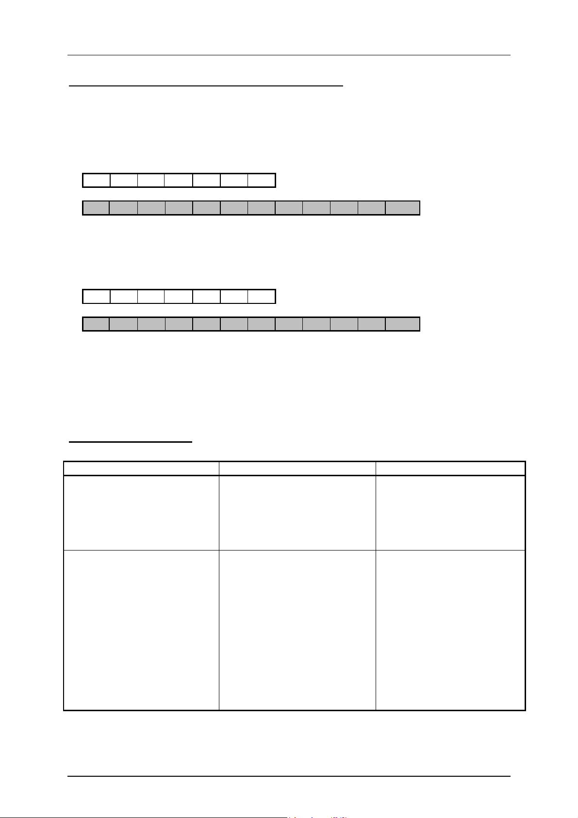
5.1 Read operation
Command telegram (telegram core, PLC ® CIA3SX, see also figure 7):
TL (read/write head address) (start address) (number of bytes user data)
Response telegram (telegram core, CIA3SX ® PLC, see also figure 8 or figure 9):
There are two different possible responses for this command
1. RL (read/write head address) (start address) (number of bytes user data) (user data)
or
2. RF (read/write head address) (0,0)(status no.)
The response telegram RL (see also figure 8) means error-free reception of the data.
If it is not possible to read a data carrier, an RF response telegram is received
(see also figure 9). The status number then indicates the cause of the error.
084727-01-02/03 Subject to technical modification Page 15 / 22
Page 16

EUCHNER Identsystem CIS3A-Mini
Byte
No.
0
1
2
3
4
5
Description
ASCII
C o n t e n t s
hex decimal
Number of telegram bytes 07 7
Command
identification
T
L
54
4C
Read/write head address 01 1
Start address of
user data
00
00
Number of bytes of
6
Figure 7: Command telegram "read data carrier read-only" (telegram core)
Byte
No.
0
1
2
3
4
5
user data 05 5
Description
ASCII
C o n t e n t s
hex decimal
Number of telegram bytes 0C 12
Command
identification
R
L
52
4C
Read/write head address 01 1
Start address of
user data
00
00
Number of bytes of
6
7 ... 11
user data 05 5
User data ASCII or hex resp. BCD (code-transparent)
84
76
0
0
82
76
0
0
Figure 8: Response telegram "read data carrier read-only" (telegram core)
Byte
No.
0
1
2
3
4
5
6
Figure 9: Response telegram "Read data carrier read-only (status)" (telegram core)
Description
ASCII
C o n t e n t s
hex decimal
Number of telegram bytes 07 7
Command
identification
R
F
52
46
Read/write head address 01 1
Padding data 00
00
Status number
**) Status number 02
Data carrier not in active area
hex
**)
(more status numbers see chapter 8)
82
70
0
0
084727-01-02/03 Subject to technical modification Page 16 / 22
Page 17
EUCHNER Identsystem CIS3A-Mini
5.2 Example, how to read a data carrier read-only
The DIP switch of the evaluation unit has to be set to data carrier read-only prior to power on
(see chapter 2.4.1).
Data carrier no. 1 in active range:
Command telegram to read the data carrier read-only:
07 T L 01 00 00 05
Response telegram:
12 R L 01 00 00 05 X1 X2 X3 X4 X5
(X1 - X5 = data)
Data carrier no. 2 in active range:
Command telegram to read the data carrier read-only:
07 T L 01 00 00 05
Response telegram:
12 R L 01 00 00 05 X1 X2 X3 X4 X5
(X1 - X5 = data)
And so on...
6 Command overview
Description Command telegram Response telegram
Program data-carrier (number of telegram bytes)
TP
(read/write head address)
(start address)
(number of bytes user data)
(user data)
Read data-carrier (number of telegram bytes)
TL
(read/write head address)
(start address)
(number of bytes user data)
(number of telegram bytes)
RF
(read/write head address)
(status no.)
(number of telegram bytes)
RL
(read/write head address)
(start address)
(number of bytes user data)
(user data)
or
(number of telegram bytes)
RF
(read/write head address)
(status no.)
084727-01-02/03 Subject to technical modification Page 17 / 22
Page 18

EUCHNER Identsystem CIS3A-Mini
7 Status messages
00
: No error
hex
: Data carrier not in active range
02
hex
03
: Read operation aborted
hex
or
Parity bit error for data carrier read-only
04
: Error while programming or while check-reading the data carrier
hex
: Write operation aborted.
05
hex
(Data carrier moved out of active range during write operation)
: Write operation aborted.
06
hex
Start address or number of bytes is not a multiple of the block size "4"
: Data carrier is out of active range (in TG mode only)
07
hex
: Data length larger than 16 bytes
16
hex
: Read attempt if EKS is set on data carrier read-only and data carrier read/write
18
hex
is inserted
: Read operation of a data carrier read-only with a set “number of bytes user
1D
hex
data” more than 5 bytes, or the start address of user data is ¹ byte 0
: General error.
4X
hex
Try once again to read or write the data carrier
: Error during programming data carrier read/write.
42
hex
Data carrier in read range but not in write range
084727-01-02/03 Subject to technical modification Page 18 / 22
Page 19

EUCHNER Identsystem CIS3A-Mini
8 Technical data of the evaluation unit CIA3SX
11422,5
H1 H2
LED
S1
0V
24V 0V
OUT
0VTxDRxD
S2
A B A1 B1
35 mm rail according
to DIN 46277
Bestell-Nr.
077910
99
all dimensions in mm
Technical data
Parameter Value Unit
min. nom. max.
Housing Plastic (PA 6.6)
Environmental protection IP 20
Operating temperature 0 +55 °C
Storage temperature -25 - +70 °C
Installation method 35 mm rail in accordance with
DIN 46277
Number of read/write heads 1 read/write head
Connection type Plug-in screw terminals
Connection terminals 0,14 - 2,5 mm
Operating voltage UB (regulated, residual ripple < 5%) 20 24 25 V=
Permanent power consumption (without load) - 120 140 mA
Interface, data transfer
Interface to the host control serial RS232 / RS422
(selectable via DIP switch)
Data transfer protocol 3964R
9,6 28,8 kBaudBaud rate
(selectable via DIP switch)
Data format 1 start bit, 8 data bits, 1 parity bit
(even parity), 1 stop bit
Cable length RS232 5 m
Cable length RS422 1000 m
LED indicators STATE-LED green: “Power On" (in operation)
ACTIVE-LED* yellow: "Data carrier active"
2
* The ACTIVE-LED lits yellow, if an operating data carrier is in the active range
084727-01-02/03 Subject to technical modification Page 19 / 22
Page 20

EUCHNER Identsystem CIS3A-Mini
9 Technical data of the read/write head CIT3
1)
19,7
32
1)
Free zone
4
M12x1
Center offset ,m,
1)
5
8
30
39
50 unplugged
Bestell-Nr.
077940
17
8x1
M
LED
all dimensions in mm
Technical data
Parameter Value Unit
min. nom. max.
Housing Brass, nickel plated
Environmental protection IP 65
Operating temperature 0 +50 °C
Storage temperature -25 +70 °C
Installation method non flush
Operating voltage U
B
Dynamic data transmission to CIA3SX 2 kBit/s
Connection 4-pole M8 plug connector
Cable length 5 15 m
LED indicators ACTIVE-LED yellow: Data carrier active
Notes on installation
· The length of the connection cable for the read head must not be increased (inline connection
not permitted).
via CIA3SX
(shielded)
084727-01-02/03 Subject to technical modification Page 20 / 22
Page 21

EUCHNER Identsystem CIS3A-Mini
10 Parts list (overview)
CIS3A-Mini components
Article Description Cat. No.
Data carrier
with 40 Bit fixed code memory
Data carrier
with 116 Byte EEPROM memory
Evaluation unit CIA3SX1R1G08 077 910
Read/write head CIT3ASX1N12ST 077 940
CIS3AP10D05KH040 077 865
CIS3APX10D05KH01K 077 785
Connecting cable (2 m)
(read/write head Û evaluation unit)
Connecting cable (5 m)
(read/write head Û evaluation unit)
Connecting cable (10 m)
(read/write head Û evaluation unit)
Connecting cable (15 m)
(read/write head Û evaluation unit)
Software and Documentation for CIS3A-Mini
Article Cat. No.
CIA3A-Mini manual 084 727
ActiveX-Module for WindowsÒ applications
LIYCY 4X0,25X02000-M8-1F
Connecting cable 4-pole socket
LIYCY 4X0,25X05000-M8-1F
Connecting cable 4-pole socket
LIYCY 4X0,25X10000-M8-1F
Connecting cable 4-pole socket
LIYCY 4X0,25X15000-M8-1F
Connecting cable 4-pole socket
084 641
084 642
084 643
084 644
077 855
084727-01-02/03 Subject to technical modification Page 21 / 22
Page 22

EUCHNER Identsystem CIS3A-Mini
Bibliography
[1] SIEMENS Manuals :
Connection components for S7 controls
CP 340 Point-to-point-Communication
Installation and Parameter Assignment SIEMENS-Order no.
6ES7340-1AH00-8BA0
CP 341 Point-to-point-Communication
Installation and Parameter Assignment SIEMENS-Order no.
6ES7341-1AH00-8BA0
CP 441 Point-to-point-Communication
Installation and Parameter Assignment SIEMENS-Order no.
6ES7441-1AH00-8BA0
084727-01-02/03 Subject to technical modification Page 22 / 22
 Loading...