


 Loading...
Operating Instructions
Non-Contact Safety Switch
CES-AR-C01-CH-SA (Multicode)
More than safety.

Operating Instructions Safety Switch CES-AR-C01-CH-SA
Contents
Correct use |
3 |
Possible combinations for CES components |
4 |
Exclusion of liability and warranty |
5 |
General safety instructions |
5 |
Function |
6 |
Changing the approach direction |
7 |
Mounting |
8 |
Electrical connection |
9 |
Safety in case of faults |
10 |
Fuse protection for power supply |
10 |
Requirements for connection cables |
11 |
Maximum cable lengths |
11 |
Connector assignment of safety switch CES-AR |
13 |
Connection of a single CES-AR-C |
14 |
Connection of several CES-AR-C in a switch chain |
16 |
Notes on operation with safe control systems |
18 |
Setup |
20 |
LED indicators |
20 |
Initial setup |
20 |
Functional check |
20 |
System status table |
21 |
Technical data |
22 |
Technical data for safety switch CES-AR-C01-CH-SA |
22 |
Technical data for actuator CES-A-BBA |
25 |
Technical data for actuator CES-A-BPA |
27 |
Technical data for actuator CES-A-BRN |
29 |
Ordering information and accessories |
31 |
Inspection and service |
31 |
Service |
32 |
Declaration of conformity |
33 |
2

Operating Instructions Safety Switch CES-AR-C01-CH-SA
Correct use
The Coded Electronic Safety switches series CES are safety devices for monitoring movable safety guards.
In combination with a separating safety guard and the machine control, this safety component prevents dangerous machine movements from occurring while the safety guard is open. A stop command is triggered if the safety guard is opened during the dangerous machine function.
Before safety switches are used, a risk assessment must be performed on the machine, e.g., in accordance with:
ÌÌEN ISO 13849-1, Safety of machinery. Safety related parts of control systems. General principles for design
ÌÌEN ISO 12100, Safety of machinery – General principles for design – Risk assessment and risk reduction
ÌÌIEC 62061, Safety of machinery. Functional safety of safety-related electrical, electronic and programmable electronic control systems.
Correct use includes compliance with the relevant requirements for installation and operation, for example
ÌÌEN ISO 13849-1, Safety of machinery. Safety related parts of control systems. General principles for design
ÌÌEN 1088, Safety of machinery. Interlocking devices associated with guards. Principles for design and selection
ÌÌEN 60204-1, Safety of machinery. Electrical equipment of machines. General requirements
ÌÌEN 60947-5-3, Specification for low-voltage switchgear and controlgear. Control circuit devices and switching elements. Requirements for proximity devices with defined behavior under fault conditions
The safety switch must be used only in conjunction with the designated CES actuators from EUCHNER. On the use of different actuators, EUCHNER provides no warranty for safe function.
Several devices are only allowed to be connected in series using devices intended for series connection with the CES-AR. Check the operating instructions for the related device. A combination of other CES devices or devices from other manufacturers is not allowed.
A maximum of 20 safety switches are allowed to be operated in a switch chain.
Important!
ÌÌThe user is responsible for the integration of the device into a safe overall system. For this purpose, the overall system must be validated, e.g. in accordance with EN ISO 13849-2.
ÌÌCorrect use requires observing the permissible operating parameters (see Technical data).
ÌÌIf a product data sheet is included with the product, the information on the data sheet applies in case of discrepancies with the operating instructions.
ÌÌIn the estimation of the PL for the overall system, a maximum value of 100 years can be assumed for the MTTFd according to the limit value in
EN ISO 13849-1:2008, section 4.5.2. This corresponds to a minimum value
for the PFHd of 2.47x10⁻⁸/h.
ÌÌWhen up to 11 devices are connected in series, these limit values can be assumed for the entire switch chain as a subsystem. As a subsystem, this switch chain achieves PL e.
3

Operating Instructions Safety Switch CES-AR-C01-CH-SA
Important!
ÌÌIn the case of series connection of more than 11 devices, the PFHd can be calculated according to one of the stated methods in EN ISO 13849-1:2008, section 4.5.1.
ÌÌIf the simplified method according to section 6.3 of EN ISO 13849:2008-12 is used for validation, the Performance Level (PL) might be reduced when more than 11 devices are connected in series.
ÌÌIt is only allowed to use components that are permissible in accordance with the table below.
Safety switches
CES-AR-C01-CH-SA
098942
Key to symbols
Note:
Possible combinations for CES components
Actuator
CES-A-BBA 071840 |
CES-A-BPA 098775 |
CES-A-BRN 100251 |
|
|
|
Combination possible
Devices with version number V 1.1.2 or higher can be operated on an AR evaluation unit. Please refer to the operating instructions for the relevant AR evaluation unit for more information.
4

Operating Instructions Safety Switch CES-AR-C01-CH-SA
Exclusion of liability and warranty
In case of failure to comply with the conditions for correct use stated above, or if the safety instructions are not followed, or if any servicing is not performed as required, liability will be excluded and the warranty void.
General safety instructions
As the unique actuator codes are not evaluated, the CES-AR-C01-CH-SA version can only be used for applications in which a hazard cannot result from possible tampering with the system.
Safety switches fulfill personal protection functions. Incorrect installation or tampering can lead to fatal injuries to personnel.
Check the safe function of the safety guard particularly ÌÌafter any setup work
ÌÌafter the replacement of a CES component ÌÌafter an extended period without use ÌÌafter every fault
Independent of these checks, the safe function of the safety guard should be checked at suitable intervals as part of the maintenance schedule.
Warning!
Danger of fatal injury in the event of incorrect connection or incorrect use. ÌÌSafety switches must not be bypassed (bridging of contacts), turned away,
removed or otherwise rendered ineffective.
On this topic pay attention in particular to the measures for reducing the possibility of bypassing from EN 1088:1995+A2:2008, section 5.7.
The device is only allowed to be installed and placed in operation by authorized personnel
ÌÌwho are familiar with the correct handling of safety components ÌÌwho are familiar with the applicable EMC regulations
ÌÌwho are familiar with the applicable regulations on health and safety and accident prevention
ÌÌwho have read and understood the operating instructions.
Caution!
Risk of damage to equipment as a result of incorrect installation. Safety switches must not be used as a mechanical end stop.
ÌÌFit an additional end stop for the movable part of the safety guard.
Important!
Prior to use, read the operating instructions and keep these in a safe place. Ensure that the operating instructions are always available during mounting, setup and servicing work. EUCHNER cannot provide any warranty in relation to the readability of the CD for the storage period required. For this reason you should archive a printed copy of the operating instructions. You can download the operating instructions from www.EUCHNER.de.
5

Operating Instructions Safety Switch CES-AR-C01-CH-SA
Function
The device complies with the following safety requirements: ÌÌCategory 4, PLe according to EN ISO 13849-1
ÌÌRedundant design of the circuit in the unit with self-monitoring
ÌÌThis means that the safety system still functions even if an internal component fails
ÌÌThe switch state of the semiconductor outputs is continuously monitored internally
ÌÌShort circuit detection at the safety outputs by pulse signals
The following switch-on condition applies to safety outputs OA and OB (see also
System status table and the section Typical system times):
ÌÌSafety guard closed
ÌÌBoth safety outputs (IA and IB) must be on
The system consists of the following components: coded actuator (transponder) and switch.
Every EUCHNER actuator supplied has an electronic coding (unique coding) that is read by the read head. Only if a correct coding is detected does the system accept the actuator. The code in an actuator cannot be reprogrammed.
Unlike systems with unique code detection, on the CES-AR-C01-CH-SA a specific code is not polled but instead it is only checked whether the actuator is of a type that can be detected by the system (multicode detection). There is no exact comparison of the actuator code with the code defined in the safety switch (unique code detection).
The safety switch is fastened to the fixed part of the safety guard.
The actuator attached to the movable part of the safety guard is moved towards the read head fitted in the safety switch by closing the door. When the switch-on distance is reached, power is supplied to the actuator by the read head by induction and data can be transferred.
If a permissible code is detected, the safety outputs are released.
Due to the combination of dynamic polling of the actuator and the redundant, diverse design of the safety electronics with the two feedback safety outputs, the safety switch will enter the safe state with every detectable fault.
When the safety guard is opened, the safety outputs switch off the safety circuit and the monitoring output (OUT) is switched off. The state of the safety outputs is monitored internally by two microprocessors.
If faults are detected, the safety circuit is switched off and the DIA LED illuminates. In case of devices with a DIA monitoring output, the output is switched on.
The safety switch has a redundant circuit design with self-monitoring. This means that the safety system is still effective even if a component fails.
The system is designed so that failures will not result in the loss of the safety function. The occurrence of failures is detected by cyclic self-monitoring at the latest on the next demand to close the safety contacts (e.g. on starting).
If the safety door with the actuator should settle over time, the actuator can drift out of the read head operating distance. The device recognizes this and indicates that the actuator is in the limit range (function available for V 1.1.2 and higher). This allows the safety door to be readjusted in time.
6

Operating Instructions Safety Switch CES-AR-C01-CH-SA
Changing the approach direction
Caution!
Risk of damage to equipment as a result of trapped cables.
ÌÌMake sure that the cables are not trapped or torn off when the approach direction is changed.
The active face of the read head can be adjusted in 5 directions. It is marked by the red face.
The plug connector can be realigned in 45° steps to change the direction of the cable outlet (when using elbow connectors).
1. Remove the top part of the mounting base and push the bottom part of the mounting base off the read head.
2. Unscrew the screws on the fastening bracket.
3. Undo the read head from the fastening bracket and tilt the read head forward by 90°.
¨¨ The active face is now pointing downward.
4. Hold the fastening bracket tight and turn the read head by 180°.
5. Re-tighten the screws for the read head on the fastening bracket. Tightening torque 0.6 Nm.
6. Turn the read head in 90° steps until the desired approach direction is reached.
Change the alignment of the plug connector if necessary.
7. Push the read head onto the bottom part of the mounting base and reassemble the mounting base.
7
Operating Instructions Safety Switch CES-AR-C01-CH-SA
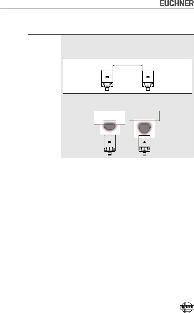
Mounting
Important!
ÌÌFrom the assured switch-off distance Sar, the safety outputs are safely shut down.
ÌÌWhen mounting several safety switches, observe the stipulated minimum distance to avoid mutual interference.
min. 80mm
ÌÌIf the actuator is installed flush, the switching distance changes as a function of the installation depth and the safety guard material.
Flush mounting |
Surface mounting |
||||
|
|
|
|
|
|
|
Actuator |
||||
|
|
|
Actuator |
||
Operating |
|
|
Operating |
||
distance |
|
|
distance |
||
|
|
|
|
|
|
Note the following points:
ÌÌActuator and safety switch must be easily accessible for inspection and replacement.
ÌÌThe switching operation must only be triggered by the specific actuator designated for this purpose.
ÌÌActuator and safety switch must be fitted so that
ÌÌthe front faces are at the minimum switch-on distance 0.8 x Sao or closer when the safety guard is closed (see section Operating distances). To avoid entering the area of possible side lobes, a minimum distance is to be maintained in case of a side approach direction. See section Typical operating distance for the related actuator.
ÌÌwhen the safety guard is open up to the distance Sar (assured switch-off distance), a hazard is excluded.
ÌÌthe actuator is positively mounted on the safety guard, e.g. by using the safety screws included.
ÌÌthey cannot be removed or tampered with using simple means.
ÌÌPay attention to the maximum tightening torque for the read head or safety switch and actuator mountings of 1 Nm. For read heads/actuators made of PE-HD, the maximum tightening torque is only 0.5 Nm.
8

Operating Instructions Safety Switch CES-AR-C01-CH-SA
Electrical connection
The following connection options are available: ÌÌSeparate operation
ÌÌSeries connection with Y-distributors from EUCHNER (only with M12 plug connector)
ÌÌSeries connection, e.g. with wiring in the control cabinet.
ÌÌOperation on an AR evaluation unit
Warning!
In the event of a fault: Loss of the safety function due to incorrect connection. ÌÌTo ensure safety, both safety outputs (OA and OB) must always be evaluated. ÌÌThe monitoring output OUT or DIA must not be used as a safety output.
ÌÌLay the connection cables with protection to prevent the risk of short circuits.
Caution!
Risk of damage to equipment or malfunctions as a result of incorrect connection. ÌÌDo not use a control system with pulsing or switch off the pulsing function in your control system. The device generates its own clock signal on the output lines OA/OB. A downstream control system must tolerate these pulses,
which may have a length of up to 1 ms.
The pulses are also output when the safety outputs are switched off. Depending on the inertia of the connected device (control system, relay, etc.), this can lead to short switching processes.
ÌÌThe inputs on an evaluation unit connected must be positive-switching, as the two outputs on the safety switch deliver a level of +24 V in the switched-on state.
ÌÌAll the electrical connections must either be isolated from the mains supply by a safety transformer according to IEC 61558-2-6 with limited output voltage in the event of a fault, or by other equivalent isolation measures (PELV).
ÌÌFor use and operation as per the  requirements, a power supply with the feature "for use in class 2 circuits" must be used. The same requirement applies to the safety outputs.
Alternative solutions must comply with the following requirements:
a)Electrically isolated power supply unit with a max. open-circuit voltage of 30 V/DC and a limited current of max. 8 A.
b)Electrically isolated power supply unit in combination with fuse as per UL248. This fuse should be designed for max. 3.3 A and should be integrated into the 30 V/DC voltage section.
ÌÌFor use and applications as per the requirements of  , a connection cable listed under the UL category code CYJV2 or CYJV must be used. The connection cables from EUCHNER meet these requirements. The same requirement applies to the safety outputs.
ÌÌAll electrical outputs must have an adequate protective circuit for inductive loads. The outputs must be protected with a free-wheeling diode for this purpose. RC interference suppression units must not be used.
ÌÌPower devices which are a powerful source of interference must be installed in a separate location away from the input and output circuits for signal processing. The cable routing for safety circuits should be as far away as possible from the cables of the power circuits.
9

Operating Instructions Safety Switch CES-AR-C01-CH-SA
Caution!
ÌÌIn order to avoid EMC interference, the physical environmental and operating conditions at the installation site of the device must comply with the requirements according to the standard EN 60204-1:2006, section 4.4.2 (EMC).
ÌÌPlease pay attention to any interference fields in case of devices such as frequency converters or induction heating systems. Observe the EMC instructions in the manuals from the respective manufacturer.
Important!
If the device does not appear to function when operating voltage is applied (e.g. green STATE LED does not flash), the safety switch must be returned unopened to the manufacturer.
Safety in case of faults
ÌÌThe operating voltage UB is reverse polarity protected. ÌÌThe contacts OA/OB are short circuit proof.
ÌÌA short circuit between OA and OB is detected by the switch.
ÌÌA short circuit in the cable can be excluded by laying the cable with protection.
Fuse protection for power supply
The power supply must be provided with fuse protection depending on the number of switches and current required for the outputs. The following rules apply:
Max. current consumption of an individual switch Imax
Imax |
= IUB + IOUT + IOA+OB |
IUB |
= Switch operating current (50 mA) |
IOUT |
= Monitoring output load current (max. 200 mA) |
IOA+OB = Load current of safety outputs OA + OB (2 x max. 400 mA)
Max. current consumption of a switch chain Σ Imax
Σ Imax = IOA+OB + n x (IUB + IOUT)
n = Number of connected switches
10
Operating Instructions Safety Switch CES-AR-C01-CH-SA
Requirements for connection cables
Caution!
Risk of damage to equipment or malfunctions as a result of incorrect connection cables.
ÌÌUse connection components and connection cables from EUCHNER
ÌÌOn the usage of other connection components, the requirements in the following table apply. EUCHNER provides no warranty for safe function in case of failure to comply with these requirements.
Observe the following requirements with respect to the connection cables:
Parameter |
Value |
Unit |
|
|
|
Conductor cross-section |
0.34 |
mm² |
|
|
|
R max. |
60 |
Ω/km |
C max. |
120 |
nF/km |
|
|
|
L max. |
0.65 |
mH/km |
|
|
|
Recommended cable type |
LIYY 8x or 5x 0.34 mm² |
|
Maximum cable lengths
Switch chains are permitted up to a maximum overall cable length of 200 m taking into account the voltage drop as a result of the cable resistance (see table below with example data and case example).
|
|
lmax =200 m |
|
|
l1 |
l2 |
|
|
|
ln |
|
|
umin = 24 V -10% |
|
un = 24 V -20% |
SPS |
iout |
|
|
PLC |
|
|
|
|
5 x 0,34 mm2 |
|
|
|
CES-AR # n |
CES-AR # n-1 |
CES-AR # 1 |
n |
Iout (mA) |
l1 (m) |
Max. number of |
Possible output current per channel |
Max. cable length from the last switch |
switches |
OA/OB |
to the control system |
|
10 |
150 |
|
25 |
100 |
5 |
50 |
80 |
|
|
|
|
100 |
50 |
|
|
|
|
200 |
25 |
|
|
|
|
10 |
120 |
|
|
|
|
25 |
90 |
|
|
|
6 |
50 |
70 |
|
|
|
|
100 |
50 |
|
|
|
|
200 |
25 |
|
10 |
70 |
|
25 |
60 |
10 |
50 |
50 |
|
100 |
40 |
|
200 |
25 |
11
Loading...