

Page 1
CET
Help for Setup and Service
Page 2

CET Help for Setup and Service
Table of contents
1 Connection................................................................................................................................... 3
1.1 Control of the guard locking, single-channel .......................................................................................... 3
1.2 Control of the guard locking, dual-channel ............................................................................................ 3
1.3 Operation on safety relay .................................................................................................................... 3
2 Teach-in ...................................................................................................................................... 4
2.1 Preparing device for teach-in operation ................................................................................................ 4
2.2 Actuator teach-in ................................................................................................................................ 4
3 Troubleshooting ........................................................................................................................... 5
3.1 LED STATE flashes twice (separate operation) ...................................................................................... 5
3.2 LED STATE flashes twice (series operation) .......................................................................................... 6
3.3 LED STATE flashes three times ........................................................................................................... 6
3.4 LED STATE flashes 4 times (separate or series operation)..................................................................... 7
3.5 LED STATE flashes five times .............................................................................................................. 8
3.6 Separate operation functions on the safety relay, but not series operation .............................................. 8
4 System status tables .................................................................................................................... 9
4.1 CET-AR and CET-AP ............................................................................................................................ 9
Page 2 of 10 Subject to technical modifications 01/2013
Page 3

CET Help for Setup and Service
1 Connection
1.1 Control of the guard locking, single-channel
The guard locking is typically controlled by a PLC via one channel. The guard locking (0V UCM) and the control system
must share the same ground connection.
The monitoring of the position of the actuator, which represents the locking device as defined in EN 1088, is suitable
for PL e.
1.2 Control of the guard locking, dual-channel
For two-channel control of the solenoid voltage by safe outputs of a control system, the following points must be
observed:
• If possible, switch off the pulsing of the outputs in the control system.
• For devices with teach-in input J, the input must remain unswitched in normal operation.
• Freely controllable LEDs may only be switched in parallel to the solenoid (i.e. the LED indicates whether the
solenoid is energized).
Tip: see www.euchner.de for application examples.
1.3 Operation on safety relay
The CET-AR can be connected to most conventional safety relays. Since the outputs, similar to those on a so-called
OSSD on light barriers or light curtains, produce clock pulses, a connection as described for non-contact systems
must be used.
Page 3 of 10 Subject to technical modifications 01/2013
Page 4
CET Help for Setup and Service
2 Teach-in
2.1 Preparing device for teach-in operation
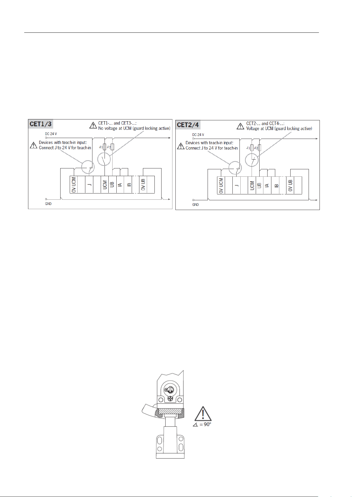
Connect the CET as shown below, but do not apply any voltage to UB yet.
In case of version with teach-in input: For the teach-in standby state, the teach-input J must be reconnected from
0 V to +24 V DC. Important: In normal operation reconnect the teach-in input to 0 V.
In case of version without teach-in input: The circuit is the same, but connection J is omitted.
Observe different control of guard locking for CET1/3 and CET2/4.
2.2 Actuator teach-in
1. Switch on operating voltage UB.
The green LED flashes quickly (approx. 10 Hz).
A self-test is performed during this time (approx. 8s). After this, the green LED flashes cyclically three times and
signals that it is in standby state for teach-in. Standby state for teach-in remains active for approx. 3 minutes.
If the red LED is illuminated, there is a fault. Teach-in is not possible. The green LED indicates the fault code.
Diagnostics see section System status table on page 9.
2. Activate guard locking.
CET1/3: no voltage at UCM.
CET2/4: voltage at UCM.
3. Fully insert new actuator into the recess. Do not cant it; place it in the center of the recess (see picture below).
Teach-in operation starts, green LED flashes (approx. 1Hz). The teach-in operation is completed after approx.
60 seconds and all the LEDs go out.
4. Switch off operating voltage UB (min. 3 seconds).
The code of the actuator that was just taught in is activated in the safety switch.
5. In case of version with teach-in input: Connect teach-in input to 0V.
6. Switch on operating voltage UB.
The device operates normally.
Page 4 of 10 Subject to technical modifications 01/2013
Page 5

CET Help for Setup and Service
3 Troubleshooting
3.1 LED STATE flashes twice (separate operation)
Fault symptom:
The CET-AR displays the fault state “input error (e.g. missing test pulses)”.
Possible fault causes:
24 V DC missing at inputs I
A safety evaluation unit or a safe control system with pulsing outputs is connected the inputs I
Remedy:
1. Check the wiring and correct it if necessary or switch the clock pulses off
2. Switch the voltage off
or
Press the reset button (if present) that controls the integrated reset input
3. Switch the voltage on again
or
Release the reset button
4. Wait until LED STATE flashes three times or stops flashing entirely (after approx. 8 s)
5. Close the safety door
The CET-AR is now operational again, the LED STATE stops flashing
and/or IB
A
and/or IB.
A
Page 5 of 10 Subject to technical modifications 01/2013
Page 6

CET Help for Setup and Service
Flashes three times
3.2 LED STATE flashes twice (series operation)
Fault symptom:
The CET-AR displays the fault state “Input fault (e.g. missing test pulses, illogical switching state of downstream
switch)”.
Possible fault causes:
24 V DC missing at inputs I
In a series circuit, I
is connected with OB or IB is connected with OA
A
In a series circuit, conventional safety components (switching contacts) are connected to I
A safety evaluation unit or a safe control system with pulsing outputs is connected the inputs I
and/or IB (only first device in series)
A
and/or IB
A
and/or IB.
A
All connections are correct, but there is no common potential for the series-connected devices (several power
supply units for one chain)
One of the units' power supply was briefly interrupted.
Remedy:
1. Check the wiring and correct it if necessary or switch the clock pulses off
2. Press the reset button that controls ALL installed reset inputs for the series circuit.
3. Release the reset button again.
4. Wait until LEDs STATE flash three times or stop flashing entirely (after approx. 8 s)
5. Close the safety doors
The CET-AR are now ready for operation again
3.3 LED STATE flashes three times
The device indicates that it is ready to teach in a new actuator. Observe the corresponding specifications for teaching
in an actuator in the system manual.
Page 6 of 10 Subject to technical modifications 01/2013
Page 7

CET Help for Setup and Service
Flashes four times
3.4 LED STATE flashes 4 times (separate or series operation)
Fault symptom:
The CET-AR displays the fault state “output fault”.
Possible fault causes:
The evaluation unit connected to the CET and the CET do not have a common reference potential (common
ground)
A ground loop has been produced by bridges having been installed both on the CET and in the control cabinet
(refer to the system manual for this purpose).
The internal output circuit is damaged.
24V present at output O
Remedy:
1. Check the wiring and correct it
2. Switch off the voltage on the CET
or
Press the reset button that controls ALL reset inputs of the series circuit
3. Switch the voltage on again
or
Release the reset button
4. Wait until LEDs DIA1 flash three times or stop flashing entirely (after approx. 8 s)
5. Close the safety doors
The CETs are now ready for operation again if no fault occurred in the internal output connection.
or OB
A
Page 7 of 10 Subject to technical modifications 01/2013
Page 8

CET Help for Setup and Service
3.5 LED STATE flashes five times
Fault symptom:
Flashes five times
The CET displays the fault state “internal fault”.
Possible fault causes:
This state occurs in the event of an internal fault
Remedy:
1. Switch all devices' voltage off
or
Press the reset button (if present) that controls the integrated reset inputs
2. Switch the voltage back on
or
Release the reset button
3. Wait until LEDs DIA1 flash three times or stop flashing entirely (after approx. 8 s)
4. Close the safety doors.
If there is no internal fault, the CETs are now ready for operation again.
3.6 Separate operation functions on the safety relay, but not series
operation
Fault symptom:
The connection of a separate CET-AR to a safety relay functions, but the connection in series to a safety relay does
not function despite correct wiring. The safety relay displays a fault or does not switch on.
Possible fault causes:
The first CET-AR is connected to the safety relay with its inputs I
supply is insufficient.
Remedy:
Connect the first inputs I
und IB directly to the 24 V DC power supply.
A
and IB, and the current that the safety relay can
A
Page 8 of 10 Subject to technical modifications 01/2013
Page 9

CET Help for Setup and Service
Flashes three times
Flashes four times
Flashes once
Flashes
inversely once
4 System status tables
4.1 CET-AR and CET-AP
Operating mode LED indicator State
Input fault (not CET-AP)
Ready for teach-in
Diagnostics
Output fault
Normal operation
Internal fault
Door closed and locked
Door closed and not locked
or
Door open
Door open
Page 9 of 10 Subject to technical modifications 01/2013
Page 10

EUCHNER GmbH + Co. KG Telephone +49 711 7597 – 500 (Support)
Kohlhammerstraße 16 Fax +49 711 753316
D-70771 Leinfelden-Echterdingen www.euchner.de . info@euchner.de
 Loading...