

Page 1

Operating instructions
Non-contact safety system
CES-AZ-UES-... (Multicode)
More than safety.
Page 2

Operating Instructions Safety System CES-AZ-UES-...
Contents
Correct Use 3
Possible combinations for CES components 4
Exclusion of Liability and Warranty 4
General Safety Instructions 5
Function 6
Block diagram CES-AZ-UES-... 8
Installation 9
Electrical Connection 11
Safety in case of faults 11
Fusing of the power supply and the safety contacts 12
Connection example CES-AZ-UES-01B 13
Connection example CES-AZ-UES-02B 14
Connection example CES-AZ-UES-04B 15
Commissioning 16
LED indicators 16
Parameter setting 16
Functional Check 18
System Status Table 20
Technical Data 22
Evaluation unit CES-AZ-AES-01B 22
Evaluation unit CES-AZ-AES-02B 24
Evaluation unit CES-AZ-AES-04B 26
Read head CES-A-LNN-... 28
Read head CES-A-LSP-... 30
Read head CES-A-LNA-... 32
Read head CES-A-LNA-SC 34
Read head CES-A-LCA-... 36
Read head CES-A-LQA-SC 38
Read head CES-A-LMN-SC 40
Actuator CES-A-BBN 42
Actuator CES-A-BSP 43
Actuator CES-A-BDN-06 44
Actuator CES-A-BBA/CES-A-BCA 45
Actuator CES-A-BQA 46
Actuator CES-A-BDA 47
Actuator CES-A-BMB 48
Ordering Information and Accessories 49
Inspection and Service 51
Service 51
Declaration of Conformity 52
2
Page 3

Operating Instructions Safety System CES-AZ-UES-...
Correct Use
The Coded Electronic Safety switches series CES are safety devices for monitoring movable safety guards.
In combination with a separating safety guard and the machine control, this safety
component prevents dangerous machine movements from occurring while the
safety guard is open. A stop command is triggered if the safety guard is opened
during the dangerous machine function.
Before safety switches are used, a risk assessment must be performed on the
machine in accordance with:
Ì EN ISO 13849-1, Safety of machinery. Safety related parts of control systems.
General principles for design
Ì EN ISO 14121-1, Safety of machinery. Risk assessment. Principles
Ì IEC 62061, Safety of machinery – Functional safety of safety-related electrical,
electronic and programmable electronic control systems.
Correct use includes compliance with the relevant requirements for installation
and operation, in particular
Important!
Ì EN ISO 13849-1, Safety of machinery. Safety related parts of control systems.
General principles for design
Ì EN 1088, Safety of machinery. Interlocking devices associated with guards.
Principles for design and selection
Ì EN 60204-1, Safety of machinery. Electrical equipment of machines. General
requirements
Ì EN 60947-5-3 Specification for low-voltage switchgear and controlgear. Con-
trol circuit devices and switching elements. Requirements for proximity devices
with defined behavior under fault conditions (PDF)
The following components can be connected to the evaluation unit CES-AZ--UES...:
Ì CES read heads
Ì CEM read heads
Ì CET read headss
For further information, refer to the operating instructions of the corresponding
component and to the following table Possible combinations for CES components.
Ì The devices permit a safety-related stop function, initiated by a safety guard
according to Table 8 - DIN EN ISO 13849-1: 2008-12.
Ì The safety-related function of the PDF is the opening of the output
contacts (13/14, 23/24) when the actuator is absent.
Ì The user is responsible for safe integration of the device in a safe overall
system. For this purpose, the overall system must be validated, e.g. in accordance with EN ISO 13849-2.
Ì The permissible operating parameters must be observed for correct use
(see Technical Data).
Ì If a product data sheet is included with the product, the information on the
data sheet applies in case of discrepancies with the operating instructions.
Ì Only components may be used that are permissible in accordance with the
table below.
3
Page 4
Operating Instructions Safety System CES-AZ-UES-...
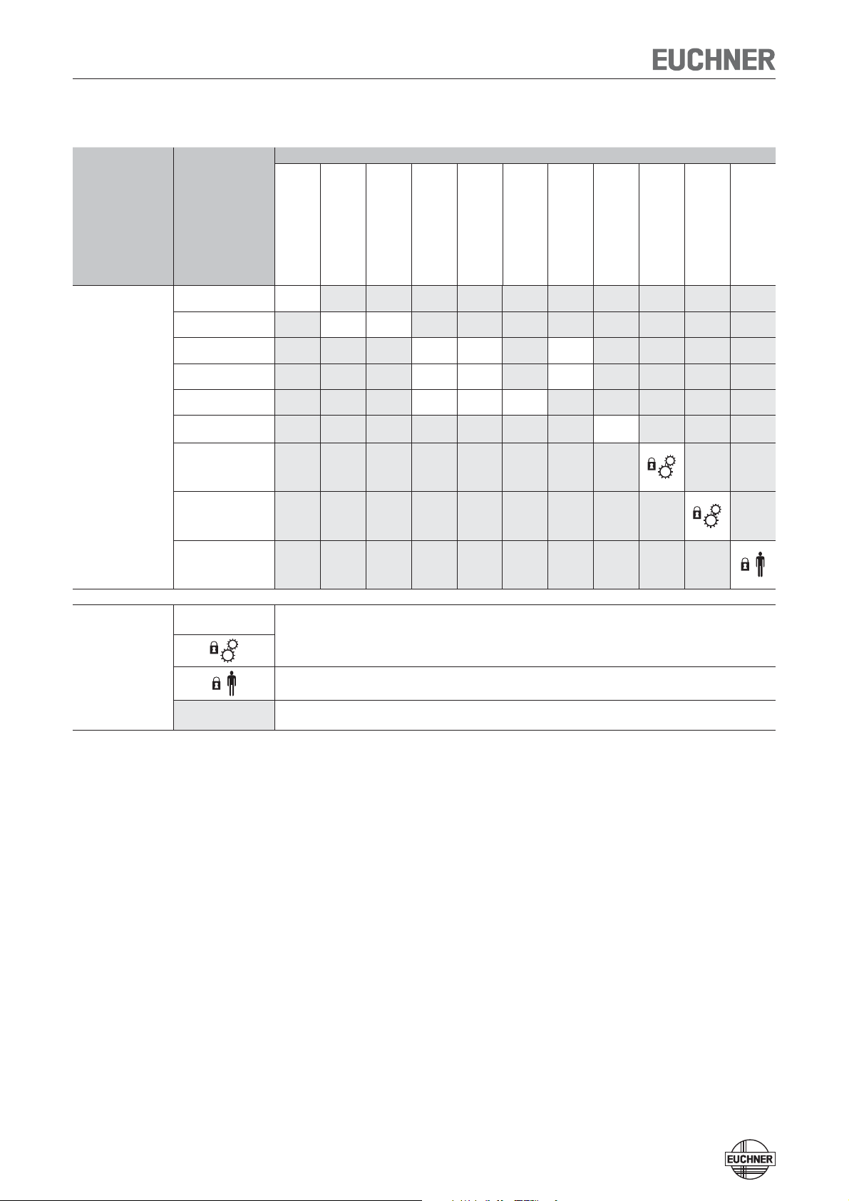
Possible combinations for CES components
Actuator
Evaluation unit
CES-AZ-UES-01B
105139
CES-AZ-UES-02B
105140
CES-AZ-UES-04B
105141
Read head/
safety switch
CES-A-BSP-104970
104970
CES-A-BBN-106600
106600
CES-A-BDN-06-104730
104730
CES-A-LSP-...
All items
CES-A-LNN-...
All items
CES-A-LCA-...
All items
CES-A-LNA-...
All items
CES-A-LQA-SC
095650
CES-A-LMN-SC
077790
CEM-A-LE05K-S2
094800
CEM-A-LE05R-S2
095792
CEM-A-LH10K-S3
095170
CEM-A-LH10R-S3
095793
CET1-AX-LRA-...
095735
CET1-AX-LDA-...
100399
15 Combination possible, typ. switch-on distance 15 mm
20
15 19
CES-A-BBA
071840
CES-A-BCA
088786
CES-A-BQA
098108
15 15 16
15 15 16
15 15 23
CES-A-BDA
084720
CES-A-BMB
077791
5
CEM-A-BE05
094805
CEM-A-BH10
095175
CET-A-BWK-50X
096327
Combination possible, guard locking for process protection
Key to symbols
Combination possible, guard locking for personal protection
Combination not permissible
Exclusion of Liability and Warranty
In case of failure to comply with the conditions for correct use stated above, or
if the safety instructions are not followed, or if any servicing is not performed as
required, liability will be excluded and the warranty void.
4
Page 5
Operating Instructions Safety System CES-AZ-UES-...
General Safety Instructions
As the unique actuator codes are not evaluated, the CES-AZ-UES-... version can only
be used for applications in which a hazard cannot result from possible tampering
with the system.
Safety switches fulfill personal protection functions. Incorrect installation or tampering can lead to severe injuries to personnel.
The number of teach-in and switching operations is saved in the internal memory
in the evaluation unit. If necessary, this memory can be read by the manufacturer.
Check the safe function of the safety guard particularly
Ì after any setup work
Ì after the replacement of a CES component
Ì after an extended period without use
Ì after every fault
Independent of these checks, the safe function of the safety guard should be
checked at suitable intervals as part of the maintenance schedule.
Warning!
Important!
Danger of fatal injury in the event of incorrect connection or incorrect use.
Ì Safety switches must not be bypassed (bridging of contacts), turned away,
removed or otherwise rendered ineffective.
On this topic pay attention in particular to the measures for reducing the possibility of bypassing from EN 1088:1995+A2:2008, section 5.7.
The device is only allowed to be installed and placed in operation by authorized
personnel
Ì who are familiar with the correct handling of safety components
Ì who are familiar with the applicable EMC regulations
Ì who are familiar with the applicable regulations on health and safety
Ì who have read and understood the operating instructions.
Prior to use, read the operating instructions and keep these in a safe place.
Ensure that the operating instructions are always available during mounting,
setup and servicing work. EUCHNER cannot provide any warranty in relation to
the readability of the CD for the storage period required. For this reason you
should archive a printed copy of the operating instructions. You can download
the operating instructions from www.EUCHNER.de.
5
Page 6

Operating Instructions Safety System CES-AZ-UES-...
Function
The safety system CES-AZ-AES... complies with the following safety requirements:
Ì Category 4, PLe according to EN ISO 13849-1
Ì Proximity device with self-monitoring type PDF-M according to EN 60947-5-3.
Ì Redundant design of the circuit in the evaluation unit with self-monitoring. As a
result, the safety system is still effective even if a component fails.
Ì When the safety guard is opened and closed, it is checked whether the safety
system relays open and close correctly.
The CES non-contact safety system consists of three components:
Ì Coded actuator
Ì Read head
Ì Evaluation unit
The number of read heads that can be connected depends on the evaluation unit:
CES-AZ-AES-01B
CES-AZ-AES-02B
CES-AZ-AES-04B ¨ 4 read heads
It is also possible to connect a start button (monitoring of the falling edge) and a
feedback loop for monitoring external relays and contactors.
The individual configuration is defined by a setup procedure.
Each delivered actuator possesses a unique electronic coding and so is a unique
element in the system used. The code in an actuator cannot be reprogrammed.
Unlike systems with unique code detection, on the CES-AZ-UES... a specific code is
not polled but instead it is only checked whether the actuator is of a type that can be
detected by the system (multicode detection). There is no exact comparison of the
actuator code with the code defined in the evaluation unit (unique code detection).
The read heads are fastened to the fixed part of the safety guard and are each
connected to the evaluation unit via a two-core screened cable.
The actuator fastened to the movable part of the safety guard is moved towards the
read head by closing the door. When the switch-on distance is reached, power is
supplied to the actuator by the read head by induction and data can be transferred.
The bit pattern read is compared with the code saved in the evaluation unit. If the
data match, the door monitoring output O1 or O1...O2 or O1...O4 (semiconductor
output) on the related read head is set HIGH. If all data for all read heads activated
match, the safety outputs (relay outputs) are then enabled. The OUT LED illuminates.
¨ 1 read head
¨ 2 read heads
Optionally, a feedback loop can be connected to the evaluation unit. The evaluation
unit can then only be started with the feedback loop closed. A welded contactor
contact in the release path will thus be detected the next time the machine is started.
Due to the combination of dynamic polling of the actuators and the redundant,
diverse design of the safety electronics with two safety outputs, the evaluation
unit will enter the safe state with every detectable fault.
When a safety guard is opened, the safety outputs switch off the safety circuit and
the OUT LED goes out. The state of the safety outputs is monitored internally by
positively driven NC contacts (relay output).
6
Page 7

Operating Instructions Safety System CES-AZ-UES-...
Independent of the switching state of the safety circuit, the position of all safety
doors can be polled via the outputs O1 or O1...O2 or O1...O4.
If an internal fault occurs in the evaluation unit, the safety circuit is switched off,
the diagnostic output (DIA) is set HIGH and the DIA LED illuminates red.
7
Page 8
Operating Instructions Safety System CES-AZ-UES-...
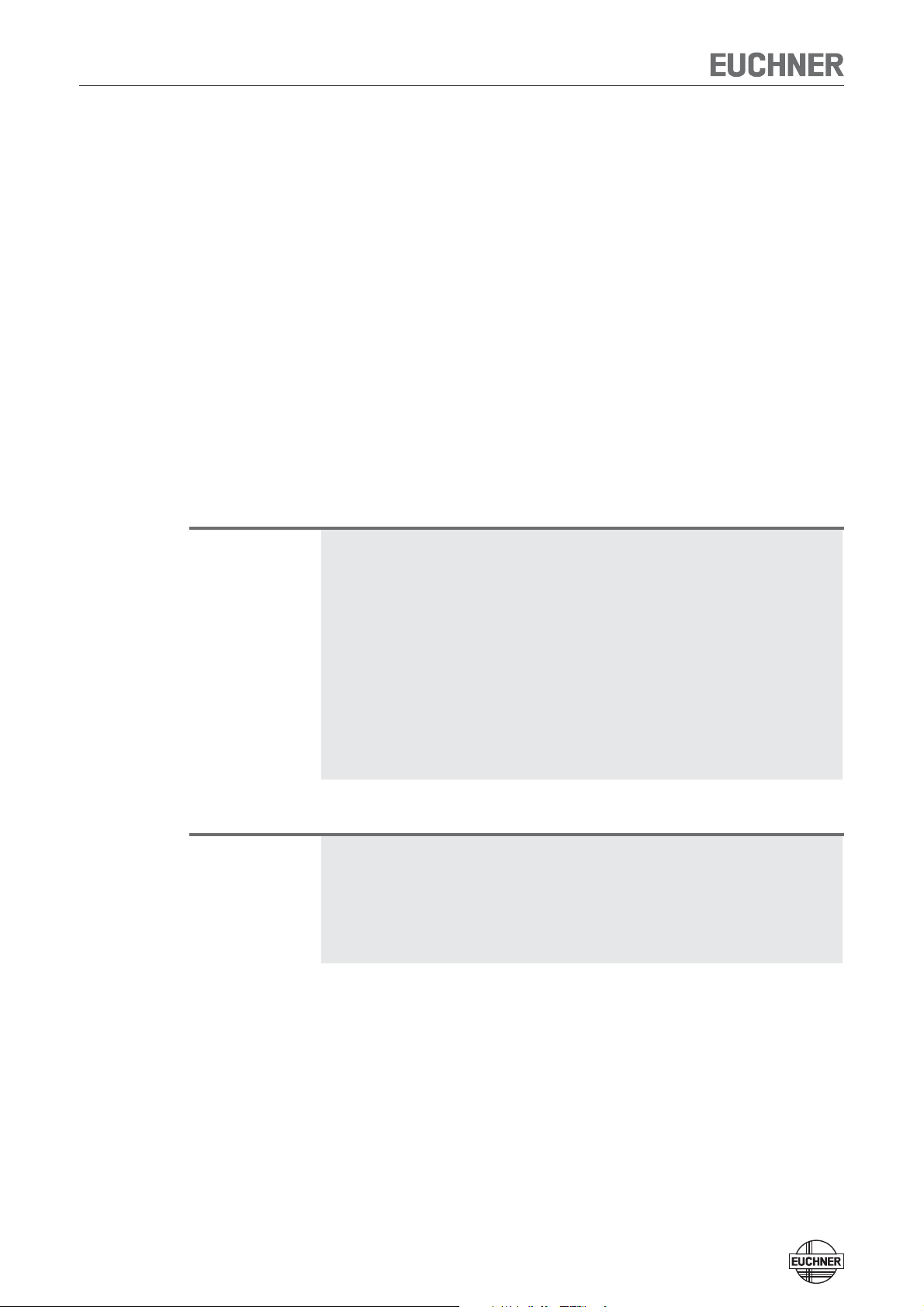
Block diagram CES-AZ-UES-...
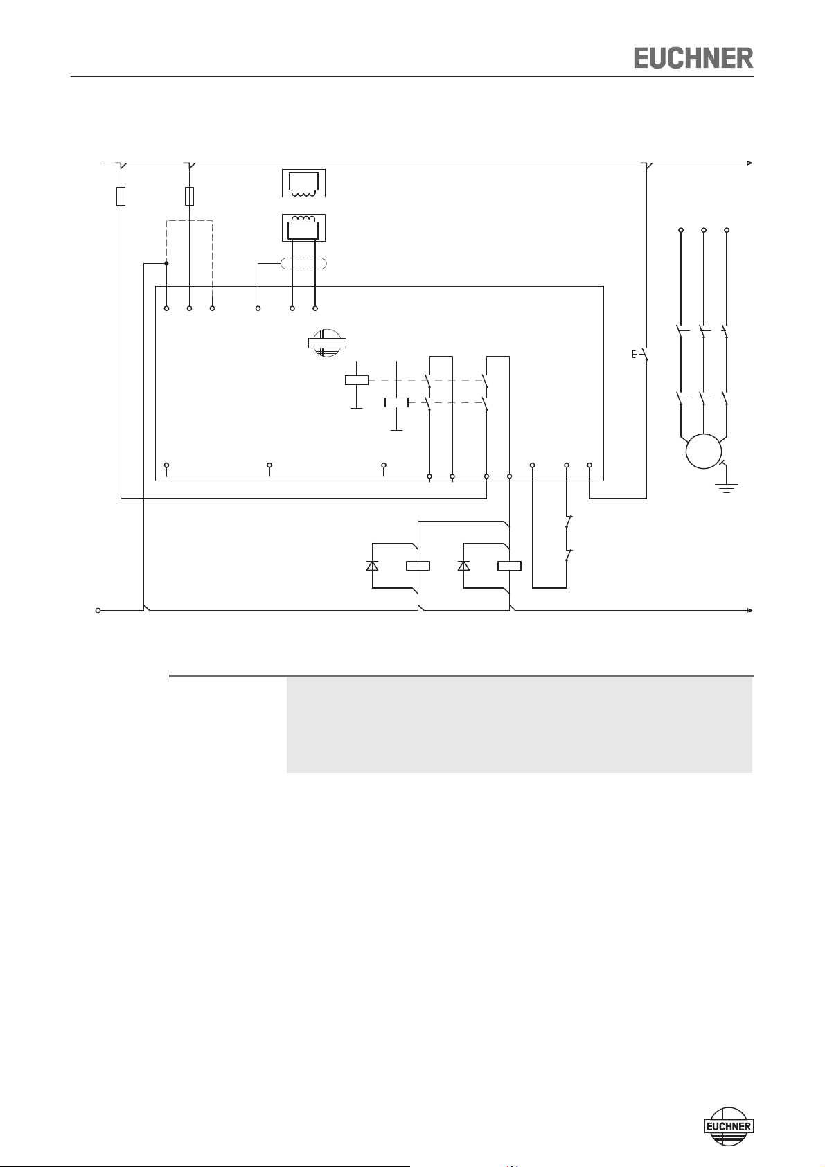
CES-AZ-UES-01B
UB, 0V Power supply
J, 0V Jumper for teach-in operation
H11/H12 Connection for read head 1
SH1 Screen read head 1
TST Test input (see „Self-test with test
O1 Semiconductor monitoring output
DIA Diagnostics output
13, 14 Connection for relay contact A,
23, 24 Connection for relay contact B,
Y1, Y2 Feedback loop
S Connection for start button
input TST“ page 18)
safety relay enable
safety relay enable
(monitoring of the falling edge)
Activation of the
teach-in operation
with jumper
on J, 0V.
0V
UB
J
CES-AZ-UES-01B
105139
TST
SH1
O1
Transponder
Readhead
H11
1
H12
EUCHNER
+
K2
K1
DIA
+
23 24
13 14
Y1 Y2 S
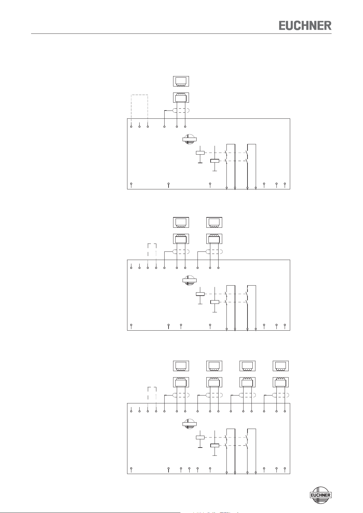
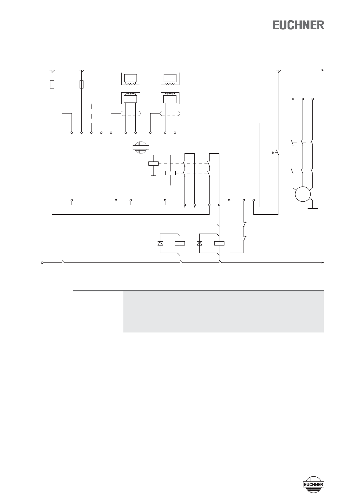
UB, 0V Power supply
J1, J2 Jumper for teach-in operation
H11/H12, H21/H22 Connection for read heads 1 and 2
SH1, SH2 Screen read heads 1 and 2
TST Test input (see „Self-test with test
O1, O2 Semiconductor monitoring outputs
DIA Diagnostics output
13, 14 Connection for relay contact A,
23, 24 Connection for relay contact B,
Y1, Y2 Feedback loop
S Connection for start button
input TST“ page 18)
safety relay enable
safety relay enable
(monitoring of the falling edge)
CES-AZ-UES-02B
Activation of the
teach-in operation
with jumper
on J1, J2.
0V
UB
J1 J2 SH1
H11
CES-AZ-UES-02B
105140
TST
O1
CES-AZ-UES-04B
Activation of the
teach-in operation
with jumper
on J1, J2.
Transponder
Readhead
H12
O2
Transponder
Readhead
1
EUCHNER
1
K2
SH2
+
K1
Transponder
Readhead
H21
DIA
Transponder
Readhead
2
H22
+
23 24 13 14
2
Transponder
Readhead
3
Y1 Y2 S
Transponder
Readhead
4
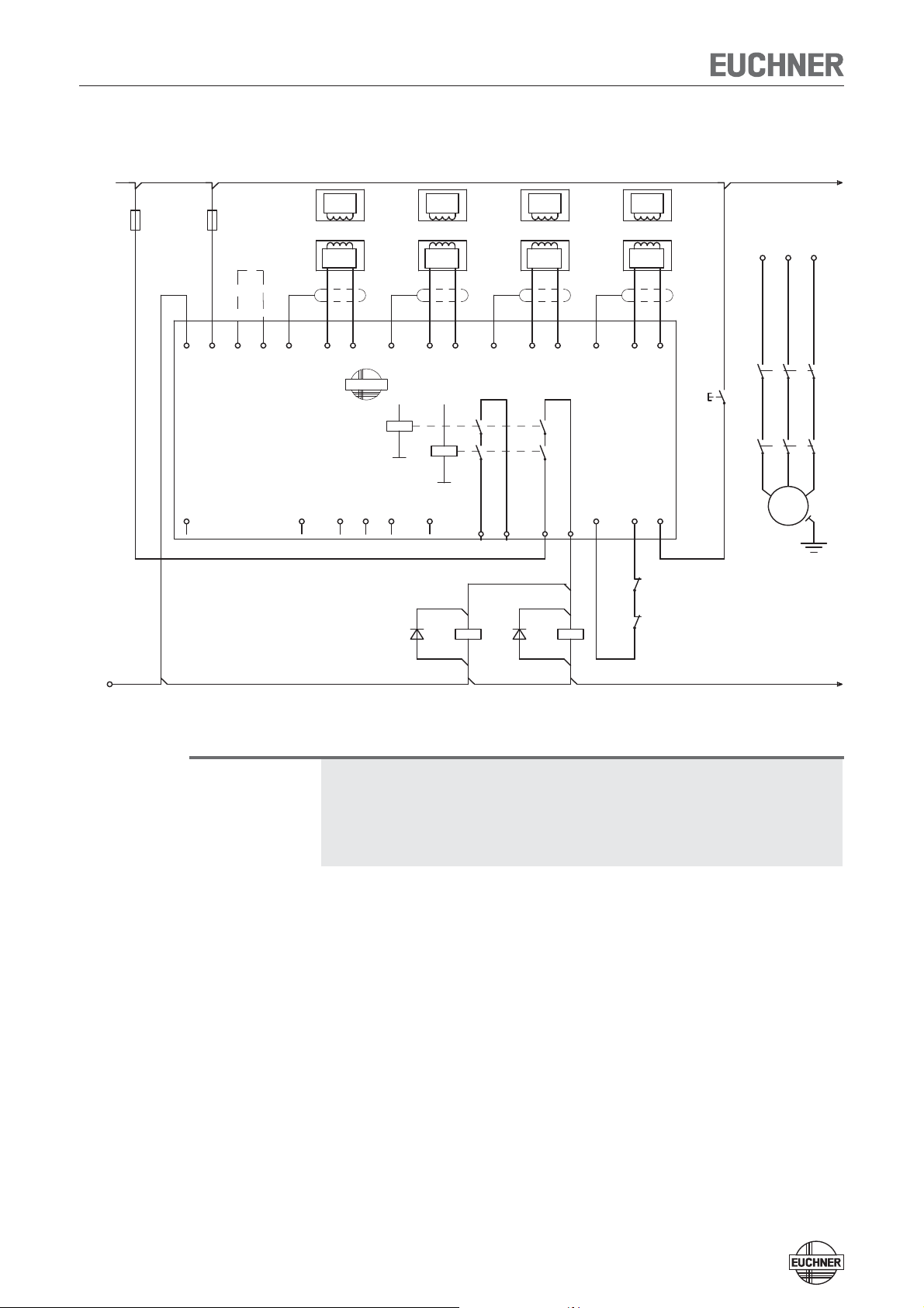
UB, 0V Power supply
J1, J2 Jumper for teach-in operation
H11/H12...H41/H42 Connection for read heads 1..0.4
SH1...SH4 Screen read heads 1...4
TST Test input (see „Self-test with test
O1...O4 Semiconductor monitoring outputs
DIA Diagnostics output
13, 14 Connection for relay contact A,
23, 24 Connection for relay contact B,
Y1, Y2 Feedback loop
S Connection for start button
input TST“ page 18)
safety relay enable
safety relay enable
(monitoring of the falling edge)
0V
UB
CES-AZ-UES-04B
105141
TST
J1 J2
SH1
O1
H11
O2
H12
8
EUCHNER
K2
O3
SH2
O4
H21
+
K1
DIA
H2223SH3
+
24
H31
13
H3214SH4
Y1
H41
Y2
H42
S
Page 9
Operating Instructions Safety System CES-AZ-UES-...
Installation
Caution!
Safety switches must not be bypassed (bridging of contacts), turned away,
removed or otherwise rendered ineffective.
Ì On this topic pay attention in particular to the measures for reducing the pos-
sibility of bypassing according to EN 1088:1995.A2:2008, sec. 5.7.
Ì The evaluation unit must be mounted in a control cabinet with a minimum
degree of protection of IP 54. A snap-in element on the rear of the device is
used for fastening to standard rails.
Ì If several evaluation units are mounted side by side in a control cabinet with-
out air circulation (e.g. fan), a minimum distance of 10 mm must be maintained between the evaluation units.
The distance enables heat from the evaluation unit to dissipate.
Caution!
Risk of damage to equipment as a result of incorrect installation. Read heads
or actuators must not be used as a mechanical end stop.
Ì Fit an additional end stop for the movable part of the safety guard.
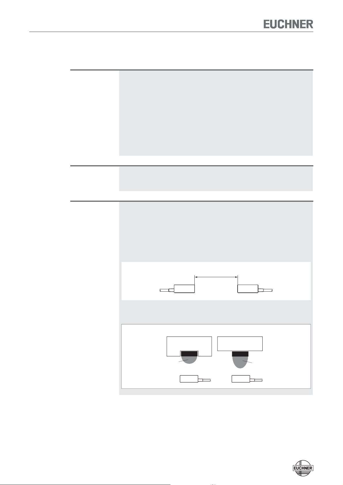
Important!
Ì From the assured switch-off distance S
, the safety outputs are safely shut
ar
down.
Ì When mounting several read heads, observe the stipulated minimum dis-
tance to avoid mutual interference.
- For CES-A-LNA/-LCA s
- For CES-A-LMN s
- For CES-A-LQA s
= 50 mm
min
= 20 mm
min
= 80 mm
min
s
min
Ì If the actuator is installed fl ush, the switching distance changes as a function
of the installation depth and the safety guard material.
Flush mounting Surface mounting
Operating
Actuator
distance
Actuator
Operating
distance
9
Page 10

Operating Instructions Safety System CES-AZ-UES-...
Note the following points:
Ì Actuator and read head must be easily accessible for inspection and replace-
ment.
Ì The switching operation must only be triggered by the specific actuator desig-
nated for this purpose.
Ì Actuator and read head must be fitted so that
Ì the front faces are at the minimum switch-on distance 0.8 x S
(see section Operating distances). To avoid entering the area of possible side
lobes, a minimum distance is to be maintained in case of a side approach
direction. See section Typical operating distance for the related actuator.
Ì when the safety guard is open up to the distance S
tance), a hazard is excluded.
Ì the actuator is positively mounted on the safety guard, e.g. by using the
safety screws included.
Ì they cannot be removed or tampered with using simple means.
Ì Pay attention to the maximum tightening torque for the read head or safety
switch and actuator mountings of 1 Nm. For read heads/actuators made of
PE-HD, the maximum tightening torque is only 0.5 Nm.
or closer
ao
(assured switch-off dis-
ar
10
Page 11
Operating Instructions Safety System CES-AZ-UES-...
Electrical Connection
Warning!
In case of an error, loss of the safety function through incorrect connection.
Ì The monitoring output OUT must not be used as a safety output.
Ì Lay the connection cables with protection to prevent the risk of short cir-
cuits.
Caution!
Risk of damage to equipment or malfunctions as a result of incorrect connection.
Ì All the electrical connections must either be isolated from the mains supply
by a safety transformer according IEC 61558-2-6 with limited output voltage
in the event of a fault, or by other equivalent isolation measures.
Ì For use and operation as per the requirements, a power supply with the
feature "for use in class 2 circuits" must be used. The same requirement applies to the safety outputs.
Alternative solutions must comply with the following requirements:
a) Electrically isolated power supply unit with a max. open-circuit voltage of 30
V/DC and a limited current of max. 8 A.
b) Electrically isolated power supply unit in combination with fuse as per UL248.
This fuse should be designed for max. 3.3 A and should be integrated into
the 30 V/DC voltage section.
Ì All electrical outputs must have an adequate protective circuit for inductive
loads. The outputs must be protected with a free-wheeling diode for this purpose.
Ì Use cable material made of copper with a temperature resistance of at least
75 °C.
Ì The tightening torque for the screws on the connection terminals must be
0.6 ... 0.8 Nm.
Ì The connection cable for the read heads must only be extended using EUCHNER
plug connectors and adequate consideration must be given to EMC. Intermediate terminals must not be used.
Ì The screen on the connection cable for the read head must be connected
to the appropriate terminal SH1 ... 4 on the evaluation unit. The portion of
cable from which insulation is stripped should be kept as short as possible
(max. 3 cm).
Safety in case of faults
Ì The operating voltage U
Ì The connections for the read heads are not short circuit-proof.
Ì A short circuit between 13/14 and 23/24 can be detected only by means of
external pulsing.
Ì A short circuit in the cable can be excluded by laying the cable with protection.
is reverse polarity protected.
B
11
Page 12

Operating Instructions Safety System CES-AZ-UES-...
Fusing of the power supply and the safety
contacts
Ì Provide external contact fuses (6 A gG fuse or 6 A circuit breaker, characteris-
tic B or C) for relay outputs.
Ì The power supply must be protected with a max. 8 A fuse before terminal U
.
B
12
Page 13
Operating Instructions Safety System CES-AZ-UES-...
Connection example CES-AZ-UES-01B
24 VDC
Transponder
-F1
-F2
0V
UB
CES-AZ-UES-01B
105139
TST
J SH1
O1
Read-
head
H11
1
H12
EUCHNER
K2
+
K1
DIA
+
23 24
13 14
Y1
Y2
L2
L1
-K3
L3
13
23
33
14
24
34
Start
13
23
-K4
14
S
-M1
33
24
34
M
~
3
GND
Important!
21
-K4
22
21
-K3
22
-V1
-K3
A1
-V2
A2
-K4
A1
A2
feedback loop
To achieve category 4 according to EN ISO 13849-1, it is necessary to monitor
the downstream contactors (here contacts of -K3 and -K4 in the feedback loop).
This example shows only an excerpt that is relevant for connection of the CES
system. The example illustrated here does not show complete system planning.
The user is responsible for safe integration in the overall system.
If only one enable path is to be used for control (e. g. of downstream contactors),
failures involving a short circuit between the contacts on the enable path and, for
example, the power supply must be excluded.
With reference to EN ISO 13849-2 Table D.5, this exclusion can be provided if
Ì the cables are inside an electrical installation space and
Ì the enclosure meets the related requirements (see EN 60204-1 or IEC 60204-1).
This example shows only an excerpt that is relevant for connection of the CES
system. The example illustrated here does not show complete system planning.
The user is responsible for safe integration in the overall system.
13
Page 14
Operating Instructions Safety System CES-AZ-UES-...
Connection example CES-AZ-UES-02B
24 VDC
-F1
-F2
0V
UB
CES-AZ-UES-02B
105140
TST
J1 J2 SH1
O1
Transponder
Read-
head
H11
O2
1
H12
EUCHNER
SH2
K2
+
H21
K1
Transponder
Readhead
DIA
2
H22
+
23 24
13 14
Y1
Y2
L2
L1
-K3
L3
13
23
33
14
24
34
Start
13
23
-K4
14
S
-M1
33
24
34
M
~
3
GND
Important!
21
-K4
22
21
-K3
22
-V1
-K3
A1
-V2
A2
-K4
A1
A2
feedback loop
To achieve category 4 according to EN ISO 13849-1, it is necessary to monitor
the downstream contactors (here contacts of -K3 and -K4 in the feedback loop).
This example shows only an excerpt that is relevant for connection of the CES
system. The example illustrated here does not show complete system planning.
The user is responsible for safe integration in the overall system.
If only one enable path is to be used for control (e. g. of downstream contactors),
failures involving a short circuit between the contacts on the enable path and, for
example, the power supply must be excluded.
With reference to EN ISO 13849-2 Table D.5, this exclusion can be provided if
Ì the cables are inside an electrical installation space and
Ì the enclosure meets the related requirements (see EN 60204-1 or IEC 60204-1).
This example shows only an excerpt that is relevant for connection of the CES
system. The example illustrated here does not show complete system planning.
The user is responsible for safe integration in the overall system.
14
Page 15
Operating Instructions Safety System CES-AZ-UES-...
Connection example CES-AZ-UES-04B
24 VDC
-F1
-F2
0V
UB
CES-AZ-UES-04B
105141
TST
J1 J2 SH1
O1
Transponder
Read-
head
H11
O2
1
H12
EUCHNER
SH2
K2
O3
O4
+
H21
K1
Transponder
Readhead
DIA
2
H22
+
23
SH3
24
Transponder
Readhead
H31
13
3
H32
14
SH4
Y1
Transponder
Readhead
H41
Y2
4
H42
S
Start
-K3
-K4
-M1
L2
L1
L3
13
23
33
14
24
34
13
23
33
14
24
34
M
~
3
GND
Important!
21
-K4
22
21
-K3
22
-V1
-K3
A1
-V2
A2
-K4
A1
A2
feedback loop
To achieve category 4 according to EN ISO 13849-1, it is necessary to monitor
the downstream contactors (here contacts of -K3 and -K4 in the feedback loop).
This example shows only an excerpt that is relevant for connection of the CES
system. The example illustrated here does not show complete system planning.
The user is responsible for safe integration in the overall system.
If only one enable path is to be used for control (e. g. of downstream contactors),
failures involving a short circuit between the contacts on the enable path and, for
example, the power supply must be excluded.
With reference to EN ISO 13849-2 Table D.5, this exclusion can be provided if
Ì the cables are inside an electrical installation space and
Ì the enclosure meets the related requirements (see EN 60204-1 or IEC 60204-1).
This example shows only an excerpt that is relevant for connection of the CES
system. The example illustrated here does not show complete system planning.
The user is responsible for safe integration in the overall system.
15
Page 16

Operating Instructions Safety System CES-AZ-UES-...
Commissioning
LED indicators
STATE LED green State display (multifunction display using flashing modes)
OUT LED yellow Safety circuit closed
DIA LED red - Operating error or
- External fault (fault in the feedback loop) or
- Internal device fault or
- TST input activated (function test active)
Parameter setting
Before the system forms a function unit, the parameters are set in the evaluation
unit by the user (number of connected read heads, with or without automatic start,
with or without feedback loop). During this process the read heads are activated.
These configuration parameters are saved in the non-volatile memory in the evaluation unit.
Important!
The safety outputs are open during the parameter assignment. The system is in
a safe state.
Ì During the parameter setting the following conditions must be met:
Ì There must be no state change, e.g. opening a safety guard or closing a
further safety guard or a change in the signal on the terminals for the start
button and the feedback circuit.
Ì The power supply must not be switched off.
Ì If these conditions are not met, the evaluation unit switches to the safe fault
state (diagnostics LED illuminates) and signals this operating fault with the
STATE LED by 3 short flashes that are repeated every second. The parameter setting operation must be repeated.
Ì The number of parameter setting operations is unlimited. The evaluation unit
can be re-configured as often as required.
Ì Do not change DIP switches during operation.
To trigger a parameter setting operation, the user must perform the following
actions in the stipulated order:
1. Prepare for parameter setting operation
Ì Switch off power supply U
B
Ì Fit a jumper between terminals J1 and J2
(for CES-AZ-AES-01B between J and 0V)
16
Page 17

Operating Instructions Safety System CES-AZ-UES-...
2. Set required configuration on DIP switches
Switch designation Switch position left (OFF) Switch position right (ON)
1 No read head connected to terminals
2 No read head connected to terminals
3 No read head connected to terminals
4 No read head connected to terminals
5 Automatic start
6 No feedback loop connected Feedback loop connected
3. Set required configuration on machine
Ì Close all doors to be monitored (the actuators must be in the operating
distance of the related read head)
Ì For Manual start operating mode: Keep start button closed
Ì For With feedback loop operating mode: keep feedback loop closed
4. Start parameter-setting operation
Ì Switch on operating voltage
Ì Wait for self-test (STATE LED flashes for approx. 10 seconds at 15 Hz)
Ì Parameter setting operation starts (STATE LED flashes at approx. 1 Hz)
Ì Wait for acknowledgement of the parameter setting operation (STATE LED
goes out after approx. 10 seconds)
H11, H12, SH1 connected
H21, H22, SH2 connected
H31, H32, SH3 connected
H41, H42, SH4 connected
(No start button connected)
Read head connected to terminals
H11, H12, SH1 connected
Read head connected to terminals
H21, H22, SH2 connected
Read head connected to terminals
H31, H32, SH3 connected
Read head connected to terminals
H41, H42, SH4 connected
Manual start
(Start button connected)
5. End parameter-setting operation
Ì Remove jumper between J1 and J2
(for CES-AZ-AES-01B between J and 0V)
Ì For Manual start operating mode: Start button must be connected
Ì For With feedback loop operating mode: Feedback loop must be con-
nected
Ì Press reset button or interrupt operating voltage for at least 10 seconds
Ì Wait for self-test (STATE LED flashes for approx. 10 seconds at 15 Hz)
6. Check all safety guards for effectiveness
Changing the configuration
The evaluation unit can be re-configured as often as required. For this purpose
you must proceed as per the first parameter setting operation according to the
section Setup.
17
Page 18

Operating Instructions Safety System CES-AZ-UES-...
Functional Check
After installation and any fault, the safety function must be fully checked. Proceed
as follows:
Warning!
Danger of fatal injury as a result of faults in installation and functional check.
Ì Before carrying out the functional check, make sure that there are no per-
sons in the danger area.
Ì Observe the valid accident prevention regulations.
1. Switch on operating voltage.
Ì The safety switch carries out a self-test.
The green STATE LED flashes for approx. 10 seconds at 15 Hz).
The STATE LED then lights up continuously.
The OUT and ERROR LEDs do not light up.
2. Close all safety guards.
Ì The machine must not start automatically.
Ì The green STATE LED and the yellow OUT LED light up continuously.
3. Enable operation in the control system.
4. Open the safety guard.
Ì The machine must switch off and it must not be possible to start it as long as
the safety guard is open.
Ì The green STATE LED lights up continuously; the OUT and ERROR LEDs do not
light up.
Repeat steps 2-4 for each safety guard.
Self-test with test input TST
On electromechanical safety switches or magnetic switches, the function test can
be performed by cyclically opening the safety guard.
From category 2 according to EN ISO 13849-1 and in accordance with EN 602041 : 1997 (sec. 9.4.2.4), a function test must be performed on the entire safety
system on start-up or after defined intervals.
Testing of the internal function of the device is not necessary because the device
monitors itself in real time. Welding of an output contact (relay output) is detected
by the device at the latest the next time the safety guard is opened. A short circuit
in the output cable is not detected by the device.
In addition, the entire safety circuit can be tested without opening the safety guard.
For this purpose, opening of the safety guard can be simulated by applying 24 V
DC to the test input TST.
The safety outputs are switched off, enabling testing of the complete safety circuit.
The diagnostic output DIA of the evaluation unit is also set HIGH as a monitoring
function.
When the test input TST is reset, the evaluation unit resets the diagnostic output
DIA to LOW, the red LED switches off and normal operation is continued.
In Manual start operating mode, the start button must be pressed again to start
the system.
18
Page 19

Operating Instructions Safety System CES-AZ-UES-...
Important:
After the self-test, test input TST must be reconnected to 0 V or disconnected.
19
Page 20

Operating Instructions Safety System CES-AZ-UES-...
System Status Table
LED
Operating mode
Commissioning
Normal operation
Function test
Fault display
Operating fault
State
STATE (green)
4 Hz Initial setup after delivery without jumper connected to J1, J2 or J, 0V.
1 Hz Parameter setting operation
15 Hz
(10 s)
3 x
4 x
OUT (yellow)
DIA (red)
Acknowledgement of completion of parameter setting operation.
Self-test, duration approx. 10 seconds, is performed after the application of the operating voltage U
Normal operation, not all monitored doors are closed.
Normal operation, all monitored doors are closed (after pressing the start button, for Manual start operating
mode)
Function test active (TST input = 24 V)
Internal component failure or actuator CES-A-BMB in the inadmissible range or excessively high external
interference (EMC)
Configuration fault:
Parameter setting operation must be performed again
Possible causes:
- State change during the parameter setting operation
- The DIP switch setting and the configuration did not match during the parameter-setting operation
- DIP switch setting has been changed without parameter setting operation
- The teach-in jumper (J1, J2 or J, 0V) was fitted with power supply switched on
- Closed feedback loop (Y1,Y2) present, although a feedback loop was not present during teach-in
- 24 V signal present at the start button input (S) although teach-in was performed with "Automatic start"
operating mode.
Fault in feedback loop
Possible causes:
- Malfunction of the monitored contactor
- Following removal from the operating distance, actuator is not outside the operating distance long enough.
- Feedback loop was not closed when the evaluation unit was started.
As a result the feedback loop cannot be closed in this short time. Note the release time for the monitored
contactor.
B
Key to symbols
Important!
N 0 Volt or not connected
1 24 Volt
0 0 Volt
LED is not lit
LED is lit
15 Hz (10 s)
3 x +
3 x
X Any state
LED flashes for 10 seconds with 15 Hz
LED flashes three times and then lights up continuously
LED flashes three times, and this is then repeated
If you cannot find the displayed device status in the system status table, this
indicates that there is an internal device fault. In this case, you should contact
the manufacturer.
20
Page 21

Operating Instructions Safety System CES-AZ-UES-...
Note!
The read heads CES-A-LNN and CES-A-LSP have an integrated LED for the indication
of the door position. The LED illuminates with the safety guard closed.
21
Page 22

Operating Instructions Safety System CES-AZ-UES-...
Technical Data
Approvals
Important:
The plug-in screw terminals are not
included (see page 48 Ordering
information and accessories).
Evaluation unit CES-AZ-AES-01B
Ì Housing for DIN rail mounting, IP 20
Ì Relay output
Ì 1 read head can be connected
Dimension drawing
22,5
H11
H12
TST
+UB
0V
Safety Unit
STATE OUT DIA
56
RESET
CES-AZ
13
O1
Y1 23
14 DIA Y2 24
SH1
S
J
S
Y
Suitable for standard 35 mm DIN rail
114
99
Switching characteristics
2 safety outputs
Ì
with 2 NO contacts each
(relay outputs)
Ì 1 door monitoring output
(semiconductor output,
not a safety output)
Closed
(actuator detected)
Read head Actuator Read head
13
23
VO1
24
Safety guard
14
24
(actuator not in the
operating distance)
13
23
24 V O1
Open
14
24
22
Page 23

Operating Instructions Safety System CES-AZ-UES-...
Technical Data CES-AZ-AES-01B
Parameter
min. typ. max.
Value
Unit
Housing material Plastic PA6.6
Dimensions 114 x 99 x 22.5 mm
Weight 0.2 kg
Ambient temperature at U
= DC 24 V -20 - +55 °C
B
Atmospheric humidity, not condensing - - 80 %
Degree of protection IP20
Degree of contamination 2
Installation DIN rail 35 mm according to EN 60715
Number of read heads 1 read head per evaluation unit
Connection (plug-in screw terminals/coded) 0.14 - 2.5 mm²
Operating voltage U
For the approval according to
Current consumption I
External fuse (operating voltage U
(regulated, residual ripple < 5 %) 21 24 27 V DC
B
the following applies
(with relay energized)
B
) 0.25 - 8 A
B
1)
Operation only with UL Class 2 power supply, or equivalent measures
- 150 - mA
Safety contacts 2 (relays with internally monitored contacts)
Switching current (relay outputs)
- At switching voltage AC/DC 21 ... 60 V
- At switching voltage AC/DC 5 ... 30 V 10 - 4000
1 - 300
mA
- At switching voltage AC 5 ... 230 V (160 V ATEX) 10 - 2000
Switching load according to
Max. AC 30 V, class 2 / max. DC 60 V, class 2
External fuse (safety circuit) according to EN 60269-1 6 A gG or 6 A circuit breaker (characteristic B or C)
Utilization category to EN 60947-5-1 AC-12 60V 0.3A / DC-12 60V 0.3A
AC-12 30V 4A / DC-12 30V 4A
AC-15 230V 2A / DC-13 24V 3A
Classification according to EN 60947-5-3 PDF-M
Rated insulation voltage U
i
Rated impulse withstand voltage U
imp
250 V
4kV
Rated conditional short-circuit current 100 A
Resilience to vibration In acc. with EN 60947-5-2
Mechanical operating cycles (relays) 10 x 10
Switching delay from state change
Time difference (between the switching points of the two
relays)
2)
- - 210 ms
- - 25 ms
6
Current via feedback loop Y1/Y2 5 8 10 mA
Permissible resistance via feedback loop - - 600
Ready delay
Dwell time
Switching frequency max.
3)
4)
5)
-1012s
3- -s
- - 0.25 Hz
Ω
Repeat accuracy R according to EN IEC 60947-5-3 ≤ 10 %
Monitoring outputs (diagnostics DIA, door monitoring output
O1, semiconductor output, p-switching, short-circuit protected)
- Output voltage 0.8 x U
B
-U
B
V DC
- Max. load - - 20 mA
Start button input S, test input TST
- Input voltage LOW 0 - 2
HIGH
15 - U
B
V DC
- Input current HIGH 5 8 10 mA
EMC protection requirements In acc. with EN 60947-5-3
Reliability figures according to EN ISO 13849-1
as a function of the switching current at 24 V DC ≤ 0.1 A ≤ 1 A ≤ 3 A
Category 4
Performance Level (PL) e
PFH
d
1.9 x 10
-8
Mission time 20 years
Number of switching cycles/year 760 000 153 000 34 600
1) Without taking into account the load currents on the monitoring outputs.
2) Corresponds to the risk time according to EN 60947-5-3. This is the maximum switch-off delay for the safety outputs following removal of the actuator. In case of EMC interference in excess
of the requirements in accordance with EN 60947-5-3, the switch-off delay can increase to max. 250 ms. After a brief actuation < 0.25 s, the switch-on delay can increase to max. 3 s if this is
followed immediately by further actuation.
3) After the operating voltage is switched on, the relay outputs are switched off and the door monitoring contact is set LOW during the ready delay. For the visual indication of the delay, the green
STATE LED flashes at a frequency of approx. 15 Hz.
4) The dwell time is the time that the actuator must be inside or outside the operating distance.
5) In case of monitoring with feedback loop, the actuators must remain outside the operating distance, e.g. with a door open, until the feedback circuit is closed.
23
Page 24

Operating Instructions Safety System CES-AZ-UES-...
Evaluation unit CES-AZ-AES-02B
Approvals
Important:
The plug-in screw terminals are not
included (see page 48 Ordering
information and accessories).
Ì Housing for DIN rail mounting, IP 20
Ì Relay output
Ì 2 read heads can be connected
Dimension drawing
45
13
TST
S
J1
STATE OUT DIA
5612
O2
O1
Y1
23
14
DIA
J2
H1
H2
S
Y
Y2
24
H11
H21
Safety Unit
RESET
CES - AZ
+UB0VSH1
H12
SH2
H22
1
4
1
9
9
Suitable for 35-mm DIN rail according to EN 60715
Switching characteristics
2 safety outputs
Ì
with 2 NO contacts each
(relay outputs)
Ì 2 door monitoring outputs
(semiconductor outputs,
not safety outputs)
Closed
(all actuators detected)
Safety guard
(e.g. actuator 1 not in the
Open
operating distance)
Read head 1 Actuator 1 Read head 1
13
23
14
24
24 V O 1
24 V O 2
13
23
VO1
24
24 V O 2
14
24
24
Page 25

Operating Instructions Safety System CES-AZ-UES-...
Technical Data CES-AZ-AES-02B
Parameter
min. typ. max.
Value
Unit
Housing material Plastic PA6.6
Dimensions 114 x 99 x 45 mm
Weight 0.25 kg
Ambient temperature at U
Atmospheric humidity, not condensing - - 80 %
= DC 24 V -20 - +55 °C
B
Degree of protection IP20
Degree of contamination 2
Installation DIN rail 35 mm according to EN 60715
Number of read heads Max. 2 read heads per evaluation unit
Connection (plug-in screw terminals/coded) 0.14 - 2.5 mm²
Operating voltage U
For the approval according to
Current consumption I
External fuse (operating voltage U
Safety contacts 2 (relays with internally monitored contacts)
(regulated, residual ripple < 5 %) 21 24 27 V DC
B
the following applies
(with relay energized)
B
) 0.4 - 8 A
B
1)
Operation only with UL Class 2 power supply, or equivalent measures
- 150 - mA
Switching current (relay outputs)
- At switching voltage AC/DC 21 ... 60 V
- At switching voltage AC/DC 5 ... 30 V 10 - 6000
1 - 300
mA
- At switching voltage AC 5 ... 230 V 10 - 2000
Switching load according to
Max. AC 30 V, class 2 / max. DC 60 V, class 2
External fuse (safety circuit) according to EN 60269-1 6 A gG or 6 A circuit breaker (characteristic B or C)
Utilization category to EN 60947-5-1 AC-12 60V 0.3A / DC-12 60V 0.3A
AC-12 30V 6A / DC-12 30V 6A
AC-15 230V 2A / DC-13 24V 3A
Classification according to EN 60947-5-3 PDF-M
Rated insulation voltage U
Rated impulse withstand voltage U
Rated conditional short-circuit current 100 A
i
imp
Resilience to vibration In acc. with EN 60947-5-2
Mechanical operating cycles (relays) 10 x 10
Switching delay from state change
2)
- 2 activated actuators - - 290
- 1 activated actuator - - 210
Time difference between the switching points
of the two relays (with 2 activated actuators)
- - 25 ms
250 V
4kV
6
ms
Manual start operating mode
- Duration of operation of start button 250 - -
- Start button response delay - 200 300
ms
Current via feedback loop Y1/Y2 5 8 10 mA
Permissible resistance via feedback loop - - 600
Ready delay
Dwell time
Switching frequency max.
3)
4)
5)
-1012s
3- -s
- - 0.25 Hz
Ω
Repeat accuracy R according to EN IEC 60947-5-3 ≤ 10 %
Monitoring outputs (diagnostics DIA, release 01...02, semi-
conductor output, p-switching, short circuit-protected)
- Output voltage 0.8 x U
- Max. load - - 20 mA
B
-U
B
V DC
Start button input S, test input TST
- Input voltage LOW 0 - 2
HIGH 15 - U
- Input current HIGH 5 8 10 mA
B
V DC
EMC protection requirements In acc. with EN 60947-5-3
Reliability figures according to EN ISO 13849-1
as a function of the switching current at 24 V DC ≤ 0.1 A ≤ 1 A ≤ 3 A
Category 4
Performance Level (PL) e
PFH
d
Mission time 20 years
1.9 x 10
-8
Number of switching cycles/year 760 000 153 000 34 600
1) Without taking into account the load currents on the monitoring outputs.
2) Corresponds to the risk time according to EN 60947-5-3. This is the maximum switch-off delay for the safety outputs following removal of the actuator. In case of EMC interference in excess of
the requirements in accordance with EN 60947-5-3, the switch-off delay can increase to max. 430 ms. After a brief actuation < 0.4 s, the switch-on delay can increase to max. 3 s if this is followed immediately by further actuation.
3) After the operating voltage is switched on, the relay outputs are switched off and the monitoring outputs are set LOW during the ready delay. For the visual indication of the delay, the green
STATE LED flashes at a frequency of approx. 15 Hz.
4) The dwell time is the time that the actuator must be inside or outside the operating distance.
5) In case of monitoring with feedback loop, the actuators must remain outside the operating distance, e.g. with a door open, until the feedback circuit is closed.
25
Page 26

Operating Instructions Safety System CES-AZ-UES-...
Evaluation unit CES-AZ-AES-04B
Approvals
Important:
The plug-in screw terminals are not
included (see page 48 Ordering
information and accessories).
Ì Housing for DIN rail mounting, IP 20
Ì Relay output
Ì 4 read heads can be connected
Dimension drawing
45
13
TST
S
J1
STATE OUT DIA
O2
O1
Y1
23
DIA
J2
H1
H2
H3
H4
S
Y
O3
O4
Y2
14
24
H11
H21
Safety Unit
RESET
CES - AZ
H31
H41
+UB0VSH1
H12
SH2
H22
H32
SH3
H42
SH4
114
99
Suitable for 35-mm DIN rail according to EN 60715
Switching characteristics
Ì
2 safety outputs
with 2 NO contacts each
(relay outputs)
Ì 4 door monitoring outputs
(semiconductor outputs,
not safety outputs)
Closed
(all actuators detected)
Safety guard
(e.g. actuator 1 not in the
operating distance)
Read head 1 Actuator 1 Read head 1
13
23
14
24
24 V O 1
24 V O 2
13
23
VO1
24
24 V O 2
24 V O 3 24 V O 3
24 V O 4 24 V O 4
Open
14
24
26
Page 27

Operating Instructions Safety System CES-AZ-UES-...
Technical Data CES-AZ-AES-04B
Parameter
Housing material
min. typ. max.
Value
Plastic PA6.6
Unit
Dimensions 114 x 99 x 45 mm
Weight 0.25 kg
Ambient temperature at U
Atmospheric humidity, not condensing - - 80 %
= DC 24 V -20 - +55 °C
B
Degree of protection IP20
Degree of contamination 2
Installation DIN rail 35 mm according to EN 60715
Number of read heads Max. 4 read heads per evaluation unit
Connection (plug-in screw terminals/coded) 0.14 - 2.5 mm²
Operating voltage U
For the approval according to
Current consumption I
External fuse (operating voltage U
Safety contacts 2 (relays with internally monitored contacts)
(regulated, residual ripple < 5 %) 21 24 27 V DC
B
(with relay energized)
B
the following applies
) 0.4 - 8 A
B
1)
Operation only with UL Class 2 power supply, or equivalent measures
- 150 - mA
Switching current (relay outputs)
- At switching voltage AC/DC 21 ... 60 V
- At switching voltage AC/DC 5 ... 30 V 10 - 6000
1 - 300
mA
- At switching voltage AC 5 ... 230 V 10 - 2000
Switching load according to
Max. AC 30 V, class 2 / max. DC 60 V, class 2
External fuse (safety circuit) according to EN 60269-1 6 A gG or 6 A circuit breaker (characteristic B or C)
Utilization category to EN 60947-5-1 AC-12 60V 0.3A / DC-12 60V 0.3A
AC-12 30V 6A / DC-12 30V 6A
AC-15 230V 2A / DC-13 24V 3A
Classification according to EN 60947-5-3 PDF-M
Rated insulation voltage U
Rated impulse withstand voltage U
Rated conditional short-circuit current 100 A
i
imp
Resilience to vibration In acc. with EN 60947-5-2
Mechanical operating cycles (relays) 10 x 10
Switching delay from state change
2)
250 V
4kV
6
- 4 activated actuators - - 450
- 3 activated actuators - - 370
- 2 activated actuators - - 290
ms
- 1 activated actuator - - 210
Time difference between the switching points
of the two relays (with 4 activated actuators)
- - 25 ms
Manual start operating mode
- Duration of operation of start button 250 - -
- Start button response delay - 200 300
ms
Current via feedback loop Y1/Y2 5 8 10 mA
Permissible resistance via feedback loop - - 600
Ready delay
Dwell time
Switching frequency max.
3)
4)
5)
-1012s
3- -s
- - 0.25 Hz
Ω
Repeat accuracy R according to EN IEC 60947-5-3 ≤ 10 %
Monitoring outputs (diagnostics DIA, release 01...02, semi-
conductor output, p-switching, short circuit-protected)
- Output voltage 0.8 x U
- Max. load - - 20 mA
B
-U
B
V DC
Start button input S, test input TST
- Input voltage LOW 0 - 2
HIGH 15 - U
- Input current HIGH 5 8 10 mA
B
V DC
EMC protection requirements In acc. with EN 60947-5-3
Reliability figures according to EN ISO 13849-1
as a function of the switching current at 24 V DC ≤ 0.1 A ≤ 1 A ≤ 3 A
Category 4
Performance Level (PL) e
PFH
d
Mission time 20 years
1.9 x 10
-8
Number of switching cycles/year 760 000 153 000 34 600
1) Without taking into account the load currents on the monitoring outputs.
2) Corresponds to the risk time according to EN 60947-5-3. This is the maximum switch-off delay for the safety outputs following removal of the actuator. In case of EMC interference in excess of
the requirements in accordance with EN 60947-5-3, the switch-off delay can increase to max. 750 ms. After a brief actuation < 0.8 s, the switch-on delay can increase to max. 3 s if this is followed immediately by further actuation.
3) After the operating voltage is switched on, the relay outputs are switched off and the monitoring outputs are set LOW during the ready delay. For the visual indication of the delay, the green
STATE LED flashes at a frequency of approx. 15 Hz.
4) The dwell time is the time that the actuator must be inside or outside the operating distance.
5) In case of monitoring with feedback loop, the actuators must remain outside the operating distance, e.g. with a door open, until the feedback circuit is closed.
27
Page 28

Operating Instructions Safety System CES-AZ-UES-...
Read head CES-A-LNN-...
Approvals
Ì Cube-shaped design 42 x 25 mm
Ì Attachment compatible with series CES-A-LNA/LCA
Ì LED for the indication of the door position
Dimension drawing
25
8
9
With
M8 plug connector
Active face
4,1
5,4
Active face
4,5
±0,1
42
32
52,7
5,3
12
LED
With
connection cable
4,6
Active face
19,4
4,1
Note
Typical operating distance
With evaluation unit CES-AZ-AES-... and actuator CES-A-BBN
Y
40
35
30
25
-30
-25
15
20
X
For a side approach direction for the actuator and read head, a minimum distance
of s = 6 mm must be maintained so that the operating distance of the side lobes
is not entered.
20
15
10
5
-5
5
5
10
-5
-1
0
-1
5
-20
-2
5
-3
0
-35
-4
0
-20
-15
-10
10
15
20
25
30
Z
28
Page 29

Operating Instructions Safety System CES-AZ-UES-...
Pin assignment
Read head with connection cable
Screen
4
BN
WH
H11 H12SH1
Evaluation unit
CES-AZ-AES-...
Technical Data
Parameter Value Unit
min. typ. max.
Housing material Reinforced thermoplastic (PBT), fully encapsulated
Dimensions 42 x 25 x 12 mm
Weight (without connection cable) 0.025 kg
Ambient temperature -25 - +70 °C
Degree of protection IP67
Installation position Any
Method of operation Inductive
Power supply Via evaluation unit
Connection type M8 plug connector, 3-pin or connection cable
LED display White, valid actuator detected
In combination with actuator CES-A-BBN-106600
Assured switch-off distance S
in y direction - - 80
Operating distance for center offset m = 0
- Switch-on distance - 15 -
- Assured switch-on distance S
- Switching hysteresis 1 4 -
In combination with actuator CES-A-BDN-06-104730
Assured switch-off distance S
in y direction - - 80
Operating distance for center offset m = 0
- Switch-on distance - 19 -
- Assured switch-on distance S
- Switching hysteresis - 4 Conductor length See ordering table 25 m
1) These values apply for the surface installation of the read head and the actuator.
in x/z direction - - 50
ar
1)
ao
in x/z direction - - 50
ar
1)
ao
10 - -
14 - -
1
3
Read head
mm
mm
29
Page 30
Operating Instructions Safety System CES-AZ-UES-...
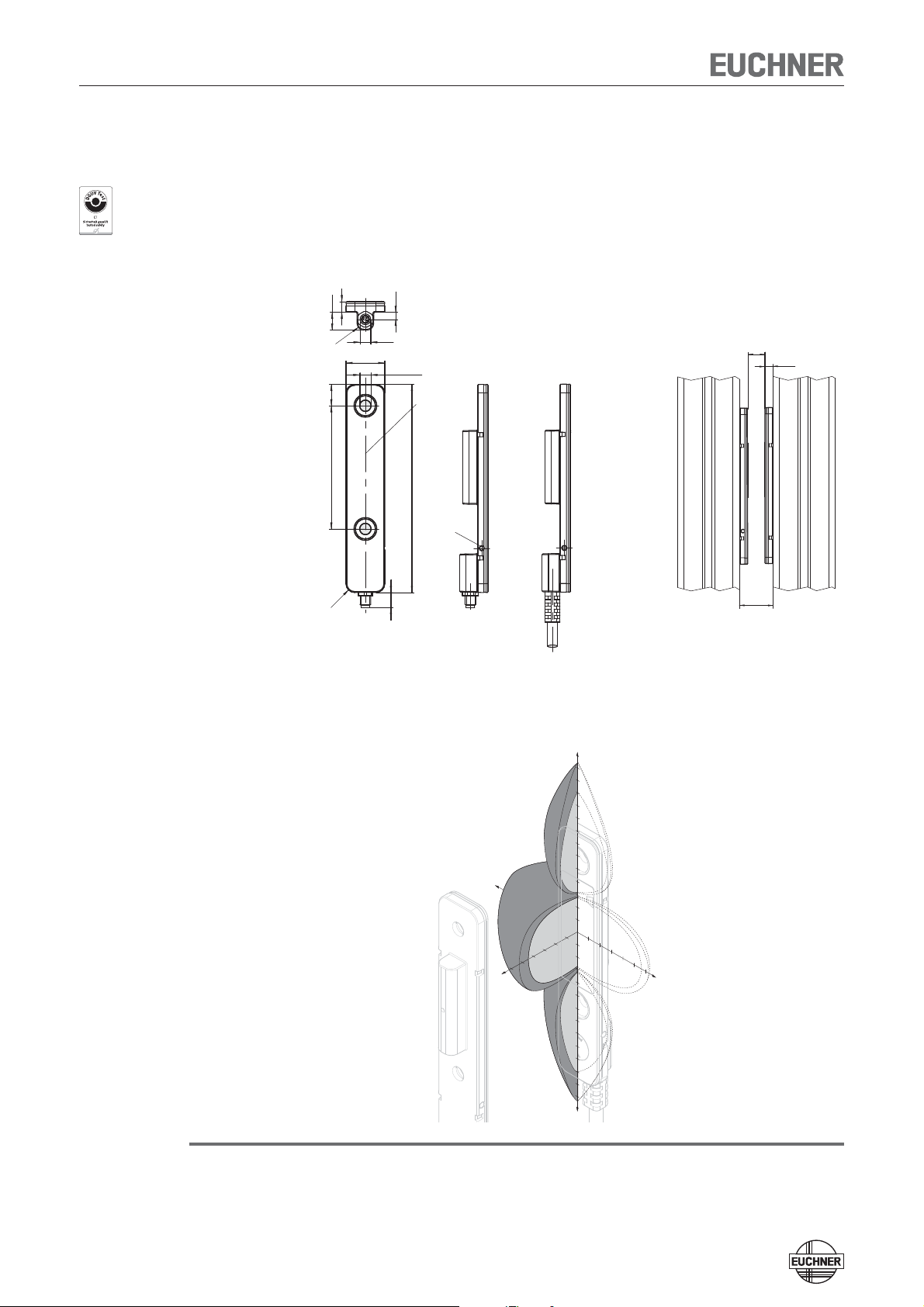
Read head CES-A-LSP-...
Approvals
Ì Optimized for aluminum profile mounting
Ì LED for the indication of the door position
Dimension drawing
18,1
3,3
M5
Ø 5,2 (2x)
7
Active face
97,1
With
M5 plug connector
LED
With
connection cable
8,3
1057,5
R4
5
R3
Mounting distance
CES-A-LSP-...
≤10
≤20
5
Note
Typical operating distance
With evaluation unit CES-AZ-AES-... and actuator CES-A-BSP
Y
65
60
55
50
45
40
35
30
25
20
15
10
5
5
10
5
10
15
20
25
30
X
15
-5
20
-10
-15
-20
-25
-30
-35
-40
-45
-5
0
-55
-60
-65
25
30
Z
For a side approach direction for the actuator and read head, a minimum distance
of s = 6 mm must be maintained so that the operating distance of the side lobes
is not entered.
30
Page 31

Operating Instructions Safety System CES-AZ-UES-...
Pin assignment
Read head with connection cable
Screen
3
Read head
BN
WH
H11 H12SH1
Evaluation unit
CES-AZ-AES-...
Technical Data
Parameter Value Unit
min. typ. max.
Housing material Reinforced thermoplastic, fully encapsulated
Weight (without connection cable) 0.02 kg
Ambient temperature -25 - +70 °C
Degree of protection IP67
Installation position Any
Method of operation Inductive
Power supply Via evaluation unit
Connection type M5 plug connector, 3-pin
LED display White, valid actuator detected
In combination with actuator CES-A-BSP-104970
Assured switch-off distance S
Operating distance for center offset m = 0
with vertical approach direction (x direction)
- Switch-on distance - 20 -
- Assured switch-on distance S
- Switching hysteresis 1 4 Conductor length See ordering table 25 m
1) These values apply for the installation of the read head and the actuator in an aluminum profile 45 x 45 mm.
--45
ar
ao
1)
10 - -
1
4
CES-A-LSP
mm
31
Page 32

Operating Instructions Safety System CES-AZ-UES-...
Read head CES-A-LNA-...
Approvals
Ì Cube-shaped design 42 x 25 mm
Ì Hard-wired cable
Dimension drawing
"l"
2 safety screws M4 x 14
included Active face Active face
42
CES-A-L XXXXXX
±0,1
32
12
4,5
25
4,6
8
Typical operating distance
With evaluation unit CES-AZ-AES-... and actuator CES-A-BBA
Y
20
15
10
5
5
10
5
10
15
20
X
15
20
Z
Note
For a side approach direction for the actuator and read head, a minimum distance
of s = 3 mm must be maintained so that the operating distance of the side lobes
is not entered.
Pin assignment
Read head with connection cable
BN
H11
Evaluation unit
CES-AZ-UES-...
WH
H12 SH1
Screen
32
Read
head
Page 33

Operating Instructions Safety System CES-AZ-UES-...
Technical Data
Parameter Value Unit
min. typ. max.
Housing material Fortron, reinforced thermoplastic, fully encapsulated
Dimensions 42 x 25 x 12 mm
Weight (incl. 10 m cable) 0.3 kg
Ambient temperature -25 - +70 °C
Degree of protection IP67/IP69K
Installation position Any
Method of operation Inductive
Power supply Via evaluation unit
In combination with actuator CES-A-BBA
Assured switch-off distance S
Operating distance for center offset m = 0
ar
1)
- Switch-on distance - 15 -
- Assured switch-on distance S
ao
- Switching hysteresis 0.5 2 Minimum distance s with lateral approach direction - 3 -
In combination with actuator CES-A-BDA
Assured switch-off distance S
Operating distance for center offset m = 0
ar
2)
- Switch-on distance - 16 -
- Assured switch-on distance S
ao
- Switching hysteresis 0.5 2 Minimum distance s with lateral approach direction - 4 Connection cable Hard-wired encapsulated connection cable, with crimped ferrules
Cable length - - 25 m
1) These values apply to non-flush installation of the read head and actuator.
2) These values apply to metal-free surrounding material. Other materials on request.
--32
10 - -
--33
11 - -
PUR, ∅ 4.8 mm, suitable for drag chain
PVC, ∅ 4.6 mm
mm
mm
33
Page 34

Operating Instructions Safety System CES-AZ-UES-...
Read head CES-A-LNA-SC
Approvals
Ì Cube-shaped design 42 x 25 mm
Ì M8 plug connector (snap-action and screw terminals)
Dimension drawing
4232,6
±0,1
32
CES-A-L 077715
A0
Active face
CES-A-L 077715
A0
25
5,5
min.38
2 safety screws M4 x 14
included
6,8
10
26,5
5
4,
Cable outlet with
angled connector
12
4,6
8
Active face
3
1
4
Note
20 1,
Typical operating distance
With evaluation unit CES-AZ-AES-... and actuator CES-A-BBA
Y
20
15
10
5
5
10
5
10
15
20
X
15
20
Z
For a side approach direction for the actuator and read head, a minimum distance
of s = 3 mm must be maintained so that the operating distance of the side lobes
is not entered.
34
Page 35

Operating Instructions Safety System CES-AZ-UES-...
Pin assignment
Read head with plug connector
WH
BN
H11 H12 SH1
Evaluation unit
CES-AZ-UES-...
Screen
3
4
1
View
on plug connector
of the read head
Technical Data
Parameter Value Unit
min. typ. max.
Housing material Fortron, reinforced thermoplastic, fully encapsulated
Dimensions 42 x 25 x 12 mm
Weight (incl. 10 m cable) 0.3 kg
Ambient temperature -25 - +70 °C
Degree of protection IP67/IP69K
Installation position Any
Method of operation Inductive
Power supply Via evaluation unit
In combination with actuator CES-A-BBA
Assured switch-off distance S
Operating distance for center offset m = 0
- Switch-on distance - 15 -
- Assured switch-on distance S
- Switching hysteresis 0.5 2 Minimum distance s with lateral approach direction - 3 -
In combination with actuator CES-A-BDA
Assured switch-off distance S
Operating distance for center offset m = 0
- Switch-on distance - 16 -
- Assured switch-on distance S
- Switching hysteresis 0.5 2 Minimum distance s with lateral approach direction - 4 Connection M8 plug connector (snap-action and screw terminals), 3-pin
Connection cable - - 25 m
1) These values apply to non-flush installation of the read head and actuator.
2) These values apply to metal-free surrounding material. Other materials on request.
ar
ao
ar
ao
1)
2)
--32
10 - -
--33
11 - -
mm
mm
35
Page 36

Operating Instructions Safety System CES-AZ-UES-...
Read head CES-A-LCA-...
Approvals
Note
Ì Cube-shaped design 42 x 25 mm
Ì Plastic PE-HD housing material, suitable for use in aggressive media (e.g. ac-
ids, alkalis)
Dimension drawing
48
42
± 0,1
32
31
25
Flat seal
l
Active face
The flat seal provided must be used during assembly.
14
12
4,6
4,5
2 safety screws M4 x 14
included
8
Active face
Typical operating distance
Note
With evaluation unit CES-AZ-AES-... and actuator CES-A-BCA
Y
20
15
10
5
5
10
5
10
15
20
X
15
20
Z
For a side approach direction for the actuator and read head, a minimum distance
of s = 3 mm must be maintained so that the operating distance of the side lobes
is not entered.
36
Page 37

Operating Instructions Safety System CES-AZ-UES-...
Pin assignment
Read head with connection cable
BN
H11
Evaluation unit
CES-AZ-UES-...
Screen
WH
H12 SH1
Read
head
View
on plug connector
of the read head
Technical Data
Parameter Value Unit
min. typ. max.
Housing material Plastic PE-HD without reinforcement, fully encapsulated
Flat seal material Fluororubber 75 FPM 4100
Dimensions 42 x 25 x 12 mm
Weight (incl. 10 m cable) 0.3 kg
Ambient temperature -25 - +50 °C
Degree of protection IP67/IP69K
Installation position Any
Method of operation Inductive
Power supply Via evaluation unit
In combination with actuator CES-A-BBA
Assured switch-off distance S
Operating distance for center offset m = 0
- Switch-on distance - 15 -
- Assured switch-on distance S
- Switching hysteresis 0.5 2 Minimum distance s with lateral approach direction - 3 -
In combination with actuator CES-A-BDA
Assured switch-off distance S
Operating distance for center offset m = 0
- Switch-on distance - 16 -
- Assured switch-on distance S
- Switching hysteresis 0.5 2 Minimum distance s with lateral approach direction - 4 Connection cable Hard-wired encapsulated connection cable, with crimped ferrules
Cable length - - 25 m
1) These values apply to non-flush installation of the read head and actuator.
2) These values apply to metal-free surrounding material. Other materials on request.
ar
ao
ar
ao
1)
2)
--32
10 - -
--33
11 - -
PVC, ∅ 4.6 mm
mm
mm
37
Page 38

Operating Instructions Safety System CES-AZ-UES-...
Read head CES-A-LQA-SC
Approvals
Ì Cube-shaped design 50 x 50 mm
Ì M8 plug connector (snap-action and screw terminals)
Dimension drawing
0
0,25
-
20,2
7
0,25
0
-
50
Ø 4,5
20
6
50
±0,15
40
Active face
Typical operating distance
x1
M8
±0,15
40
Y
30
-30
30
X
20
10
10
10
20
20
-30
With actuator CES-A-BBA or CES-A-BCA
Y
30
20
10
10
10
20
30
X
20
30
Z
30
Z
with actuator CES-A-BQA on evaluation unit CES-AZ-...-01B
38
Page 39

Operating Instructions Safety System CES-AZ-UES-...
Pin assignment
Read head with connection cable
Screen
4
BN
WH
H11 H12SH1
Evaluation unit
CES-AZ-AES-...
Technical Data
Parameter Value Unit
min. typ. max.
Housing material Fortron, reinforced thermoplastic, fully encapsulated
Dimensions 50 x 50 x 20.2 mm
Weight 0.08 kg
Ambient temperature -25 - +70 °C
Degree of protection IP67
Installation position Any
Method of operation Inductive
Power supply Via evaluation unit
In combination with actuator CES-A-BBA or CES-A-BCA
Assured switch-off distance S
Operating distance for center offset m = 0
- Switch-on distance - 15 -
- Assured switch-on distance S
- Switching hysteresis 2 3 -
In combination with actuator CES-A-BQA on evaluation unit CES-AZ-...-01B
Assured switch-off distance S
Operating distance with vertical approach direction
Center offset m = 0
- Switch-on distance - 23 -
- Assured switch-on distance S
- Switching hysteresis 2 3 Operating distance with side approach direction
Distance in x direction = 10 mm
- Switch-on distance - 28 -
- Assured switch-on distance S
- Switching hysteresis 1 1.3 Connection cable - - 25 m
1) These values apply for surface installation of the read head and the actuator.
ar
ao
--60
ar
1)
ao
ao
1)
10 - -
16 - -
24 - -
1
Read head
3
--47
mm
mm
39
Page 40

Operating Instructions Safety System CES-AZ-UES-...
Read head CES-A-LMN-SC
Approvals
Ì Cylindrical design M12
Ì M8 plug connector (snap-action and screw terminals)
Dimension drawing
m
Centre offset
s
4
1)
5
8
M8x1
30
37
35
connected
Active face
Reading distance
1)
19,7
32
M12x1
1) Clear zone (area of the active face without metal housing)
17
Note
The read head is allowed to be installed as a maximum up to the clear zone (area
of the active face without metal housing).
Typical operating distance
With evaluation unit CES-AZ-AES-... and actuator CES-A-BMB
Y
8
8
6
6
8
X
6
4
2
2
2
4
4
6
8
6
8
Z
Note
A minimum distance of s = 1.2 mm must be maintained.
40
Page 41

Operating Instructions Safety System CES-AZ-UES-...
Pin assignment
Read head with plug connector
WH
BN
H11 H12 SH1
Evaluation unit
CES-AZ-UES-...
Screen
3
4
1
View
on plug connector
of the read head
Technical Data
Parameter Value Unit
min. typ. max.
Housing material Nickel-plated CuZn housing sleeve
Dimensions M12 x 1, length 38 mm
Weight (incl. 10 m cable) 0.2 kg
Ambient temperature -25 - +70 °C
Ambient pressure
(only of active face in installed condition)
Degree of protection IP67
Installation position Any
Method of operation Inductive
Power supply Via evaluation unit
In combination with actuator CES-A-BMB on evaluation unit CES-AZ-AES-04B
Assured switch-off distance S
Operating distance for center offset m = 0
- Switch-on distance - 5 -
- Assured switch-on distance S
- Switching hysteresis 0.1 0.3 Connection M8 plug connector (snap-action and screw terminals), 3-pin
Connection cable - - 15 m
1) These values apply for surface installation of the read head in steel.
ar
ao
1)
- - 10 bar
--10
3.5 - -
Plastic PBT GF20 cap
mm
41
Page 42

Operating Instructions Safety System CES-AZ-UES-...
Actuator CES-A-BBN
Ì Cube-shaped design 42 x 25 mm
Ì Attachment compatible with series CES-A-LNA/LCA
Dimension drawing CES-A-BBN
4,5
25
8
Active face
12
42
±0,1
32
Active face
Technical Data
Parameter
Housing material Reinforced thermoplastic (PBT), fully encapsulated
Dimensions 42 x 45 x 12 mm
Weight 0.025 kg
Ambient temperature -25 - +70 °C
Degree of protection IP67
Installation position Active face opposite read head
Power supply Inductive via read head
min. typ. max.
Value
Unit
42
Page 43

Operating Instructions Safety System CES-AZ-UES-...
Actuator CES-A-BSP
Ì Optimized for aluminum profile mounting
Dimension drawing CES-A-BSP
2
R
18,1
1057,5
Active face
6
Ø 5,2
5
97,1
Technical Data
Parameter
Housing material Reinforced thermoplastic, fully encapsulated
Weight 0.02 kg
Ambient temperature -25 - +70 °C
Degree of protection IP67
Installation position Active face opposite read head
Power supply Inductive via read head
min. typ. max.
Value
Unit
43
Page 44

Operating Instructions Safety System CES-AZ-UES-...
Actuator CES-A-BDN-06
Ì Cylindrical design ∅ 6 mm
Dimension drawing CES-A-BDN-06
* min.
30
Ø
+
6,1
30
*
30
*
* metal-free zone
+
0,5
26
0
Installation options
6
0,1
0
x
y
z
Technical Data
Parameter
min. typ. max.
Housing material Macromelt PA-based plastic
Dimensions 26 x ∅ 6mm
Weight 0.005 kg
Ambient temperature -25 - +70 °C
Degree of protection IP67
Installation position Active face opposite read head
Power supply Inductive via read head
Value
Unit
44
Page 45

Operating Instructions Safety System CES-AZ-UES-...
Actuator CES-A-BBA/CES-A-BCA
Ì Cube-shaped design 42 x 25 mm
Ì CES-A-BCA suitable for use in aggressive media (e.g. acids, alkalis)
Ì In combination with read head CES-A-LNA.../CES-A-LCA...
Dimension drawing CES-A-BBA
Note
42
CES-A-B 071840
±0,1
32
2 safety screws M4 x 14
included
25
Active face
ø4,5
4,6
12
ø8
Active face
Dimension drawing CES-A-BCA
48
42
± 0,10
32
2 safety screws M4 x 14
included
Flat seal
31
25
Active face
CES-A-BCA: The flat seal provided must be used during assembly.
212
4,5
4,6
8
Active face
Technical Data
Parameter
Housing material
- CES-A-BBA Fortron, reinforced thermoplastic, fully encapsulated
- CES-A-BCA Plastic PE-HD without reinforcement, fully encapsulated
Flat seal material (CES-A-BCA only) Fluororubber 75 FPM 4100
Dimensions 42 x 25 x 12 mm
Weight 0.02 kg
Ambient temperature
- CES-A-BCA -25 - +50
Degree of protection IP67/IP69K
Installation position Active face opposite read head
Power supply Inductive via read head
min. typ. max.
Value
Unit
°C- CES-A-BBA -25 - +70
45
Page 46

Operating Instructions Safety System CES-AZ-UES-...
Actuator CES-A-BQA
Approvals
Ì Cube-shaped design 50 x 50 mm
Dimension drawing CES-A-BQA
0
0,25
-
20,2
0,25
0
-
50
Ø 4,5
6
Active face
50
±0,15
40
±0,15
40
Technical Data
Parameter
min. typ. max.
Housing material Fortron, reinforced thermoplastic, fully encapsulated
Dimensions 50 x 50 x 20.2 mm
Weight 0.07 kg
Ambient temperature -25 - +70 °C
Degree of protection IP67
Installation position Active face opposite read head
Power supply Inductive via read head
Value
Unit
46
Page 47

Operating Instructions Safety System CES-AZ-UES-...
Actuator CES-A-BDA
Ì Round design ∅ 20 mm
Ì In combination with read head CES-A-LNA.../CES-A-LCA...
Dimension drawing
∅ 20
Active face Active face
2,2
Technical data
Parameter
Housing material Plastic PC
Dimensions ∅ 20 x 2.2 mm
Weight 0.0008 kg
Ambient temperature -25 - +70 °C
Degree of protection IP67
Installation position Active face opposite read head
Power supply Inductive via read head
min. typ. max.
Ordering table
Series Version/Comment Order no./item
CES-A-BDA
-
Value
084720
CES-A-BDA-20
Unit
47
Page 48

Operating Instructions Safety System CES-AZ-UES-...
Actuator CES-A-BMB
Ì Cylindrical design M12 x 75
Ì In combination with read head CES-A-LMN-SC
(with read head CES-A-LNA.../LCA... operating distance on request)
Dimension drawing
0,80
11
M12x0,75
6
Active face
Notes
Ì The actuator can be screwed into the M12 x 0.75 thread provided with the aid
of an insertion tool (Order No. 037 662).
Ì Flush installation of the actuator in steel is allowed.
Technical Data
Parameter
Housing material Stainless steel
Dimensions M12 x 0.75, depth 6 mm
Weight 0.002 kg
Ambient temperature -25 - +70 °C
Degree of protection IP67
Installation position Active face opposite read head
Power supply Inductive via read head
min. typ. max.
Value
Unit
48
Page 49

Operating Instructions Safety System CES-AZ-UES-...
Ordering Information and Accessories
Evaluation units
Series
CES-AZ-UES...
Category according to
EN ISO 13849-1
415
Important: The plug-in screw terminals are not included.
Read heads
Series Cable/connection type Cable length "l" [m] Order no. / item
CES-A-LNN-...
M8 plug connector
CES-A-LSP-...
M5 plug connector
CES-A-LNA-...
CES-A-LNA-SC
CES-A-LCA-...
CES-A-LQA-SC
CES-A-LMN-SC
M8 plug connector -
M8 plug connector
M8 plug connector -
Typ. switch-on distance
V
Cable PVC
SC
V
Cable PVC
SB
V
Cable PVC
P
Cable PUR
V
Cable PVC
SC
[mm]
Number of read heads Order no. / item
1
2
4
5
-
5
10
15
20
25
-
5
10
15
25
5
10
15
10
-
105139
CES-AZ-UES-01B
105140
CES-AZ-UES-02B
105141
CES-AZ-UES-04B
106602
CES-A-LNN-05V-106602
106601
CES-A-LNN-SC-106601
104966
CES-A-LSP-05V-104966
104967
CES-A-LSP-10V-104967
106271
CES-A-LSP-15V-1062716
106272
CES-A-LSP-20V-106272
104968
CES-A-LSP-25V-104968
104969
CES-A-LSP-SB-104969
071845
CES-A-LNA-05V
071846
CES-A-LNA-10V
071847
CES-A-LNA-15V
071975
CES-A-LNA-25V
077806
CES-A-LNA-05P
077807
CES-A-LNA-10P
084682
CES-A-LNA-15P
077715
CES-A-LNA-SC
088785
CES-A-LCA-10V
095650
CES-A-LQA-SC
077790
CES-A-LMN-SC
49
Page 50

Operating Instructions Safety System CES-AZ-UES-...
Actuator
Series Comment Version Order no. / item
CES-A-BBN
CES-A-BSP
CES-A-BDN-06
CES-A-BBA
CES-A-BCA
CES-A-BQA
CES-A-BDA
CES-A-BMB
Accessories
Series Comment Version Order no. / item
Connection kit for evaluation units
with plug-in
screw terminals
Installation material
for read head CES-A-LSP-...
and
actuator CES-A-BSP
Insertion tool
2 safety screws M4 x 14
are supplied
Please order installation
material separately
--
2 safety screws M4 x 14
are supplied
2 safety screws M4 x 14
are supplied
Flat seal included
2 safety screws M4 x 14
are supplied
-
--
For evaluation unit CES-AZ-AES-01B Screw terminals
For evaluation unit CES-AZ-AES-02B Screw terminals
For evaluation unit CES-AZ-AES-04B Screw terminals
For Bosch profiles with 8 mm groove 2 screws and 2 clamping pieces
For Bosch profiles with 10 mm groove 2 screws and 2 clamping pieces
For ITEM profiles with 8 mm groove 2 screws and 2 clamping pieces
For actuator CES-A-BMB -
Housing material PE-HD
-
-
-
CES-A-BCA
-
Installation material 10-groove
106600
CES-A-BBN-106600
104970
CES-A-BSP-104970
104730
CES-A-BDN-06-104730
071840
CES-A-BBA
088786
098108
CES-A-BQA
084720
CES-A-BDA-20
077791
CES-A-BMB
104756
104771
104776
106633
Installation material 8-groove
Installation material 8-groove
Bosch
106634
Bosch
106635
ITEM
037662
50
Page 51

Operating Instructions Safety System CES-AZ-UES-...
Inspection and Service
Warning!
Loss of the safety function because of damage to the device.
In case of damage, the related safety component must be replaced. The replacement of individual parts in a safety component is not permitted.
Regular inspection of the following is necessary to ensure trouble-free long-term
operation:
Ì Check the switching function (see section Functional check)
Ì Check the secure fastening of the devices and the connections
Ì Check for soiling
Ì Check for sealing of the plug connector on the safety switch
Ì Check for loose cable connections on the plug connector.
Ì Check of the switch-off distance
Maintenance work is not necessary. Repairs to the device are only allowed to be
made by the manufacturer.
Note!
Service
The year of manufacture can be seen on the rating plate in the lower right corner.
If service support is required, please contact:
EUCHNER GmbH + Co. KG
Kohlhammerstraße 16
D-70771 Leinfelden-Echterdingen
Service telephone:
+49 711 7597-500
E-mail:
info@euchner.de
Internet:
www.euchner.de
51
Page 52

Operating Instructions Safety System CES-AZ-UES-...
Declaration of Conformity
52
Page 53

Operating Instructions Safety System CES-AZ-UES-...
53
Page 54

Operating Instructions Safety System CES-AZ-UES-...
54
Page 55

Operating Instructions Safety System CES-AZ-UES-...
55
Page 56

More than safety.
Euchner GmbH + Co. KG
Kohlhammerstraße 16
D-70771 Leinfelden-Echterdingen
info@euchner.de
www.euchner.de
Issue:
105274-06-10/13
Title:
Operating Instructions Safety System CES-AZ-UES-...
(Translation of the Original Operating Instructions)
Copyright:
© EUCHNER GmbH + Co. KG, 10/2013
Subject to technical modifications,
all data supplied without liability.
 Loading...