

Page 1

System Manual
Non-contact Safety System
CES-A-S5H-01 (Unicode)
More than safety.
Page 2

System Manual Safety System CES-A-S5H01
2
Contents
Correct Use 3
Possible combinations for CES components
4
Exclusion of Liability and Warranty
General Safety Instructions
System Description
Block diagram
Changing the approach direction
Installation
Electrical Connection 1
Safety in case of faults 1
Safety switch CES-A-S5... 1
Voltage drop as a function of switching current and cable length (examples) 1
Correct connection 1
Connection example 1
CES-A-S5H-01 1
Pin assignment safety switch CES-A-S5... 1
LED indicators 1
4
5
6
7
8
9
1
2
3
3
4
5
5
6
6
Reset 1
Teach-in function for actuator 1
Teach-in function for first actuator 1
Teach-in function for a new actuator 1
Functional check 1
System Status Table 1
Truth table 2
Pulse diagram 2
Technical Data 2
Safety switch CES-A-S5H-01 2
Actuator CES-A-BPA 2
Actuator CES-A-BBA 2
Position actuator CES-A-NBA-. 2
Inspection and Service 2
Service 2
Declaration of Conformity 2
6
7
7
7
8
9
0
0
1
1
3
5
6
8
8
9
Page 3

System Manual Safety System CES-A-S5H01
Correct Use
The Coded Electronic Safety switches series CES are safety devices for monitoring movable safety guards.
In combination with a separating safety guard and the machine control, this safety
component prevents dangerous machine movements from occurring while the
safety guard is open. A stop command is triggered if the safety guard is opened
during the dangerous machine function.
Before safety switches are used, a risk assessment must be performed on the
machine in accordance with:
EN ISO 13489-1, Safety of machinery. Safety related parts of control systems.
General principles for design
EN ISO 14121-1, Safety of machinery. Risk assessment. Principles
IEC 62061, Safety of machinery – Functional safety of safety-related electrical,
electronic and programmable electronic control systems.
Correct use includes compliance with the relevant requirements for installation
and operation, in particular
Important!
EN ISO 13489-1, Safety of machinery. Safety related parts of control systems.
General principles for design
EN 1088, Safety of machinery. Interlocking devices associated with guards.
Principles for design and selection
EN 60204-1, Safety of machinery. Electrical equipment of machines. General
requirements
EN 60947-5-3 Specification for low-voltage switchgear and controlgear. Con-
trol circuit devices and switching elements. Requirements for proximity devices
with defined behaviour under fault conditions (PDF)
Along with the safety function, the safety switch CES-A-S... has an identification
function that provides position sensing. The position function has no safety function
and is not allowed to be used for safety-related polling.
The safety switch CES-A-C5... is only allowed to be operated in conjunction with the
designated EUCHNER actuators (see Combinations table). On the use of a different
actuator, EUCHNER provides no warranty for safe function.
The devices are intended for use in safety circuits and, together with
connected evaluation units, permit safety functions according to
DIN EN ISO 13849-1: 2008-12 - Table 8, such as a safety-related stop function, prevention of unexpected start-up, etc.
The safety-related function of the PDF is switch-off (low) of one of the
outputs (LA, LB) when the actuator is absent.
The user is responsible for safe integration of the device in a safe overall
system. For this purpose the overall system must be validated, e.g. in accordance with EN ISO 13849-2.
The permissible operating parameters must be observed for correct use
(see Technical data).
If a product data sheet is included with the product, the information on the
data sheet applies in case of discrepancies with the operating instructions.
Only components may be used that are permissible in accordance with the
table below.
3
Page 4
System Manual Safety System CES-A-S5H01
4
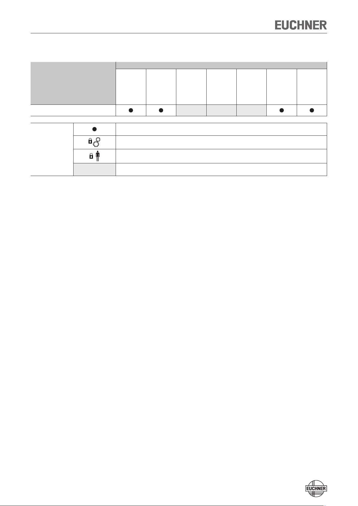
Possible combinations for CES components
Actuator
Safety switches
CES-A-BBA
071840
CES-A-S5H-01
090640
Combination possible
Combination possible, guard locking for process protection
Key to symbols
Combination possible, guard locking for personal protection
Combination not permissible
CES-A-BCA
088786
CES-A-BDA
084720
CES-A-BMB
077791
CES-A-BQA
098108
CES-A-NBA-...
All items
CES-A-BPA
098775
Exclusion of Liability and Warranty
In case of failure to comply with the conditions for correct use stated above, or
if the safety instructions are not followed, or if any servicing is not performed as
required, liability will be excluded and the warranty void.
Page 5
System Manual Safety System CES-A-S5H01
General Safety Instructions
The number of teach-in and switching operations is saved in the internal memory in
the evaluation unit. If necessary, this memory can be read by the manufacturer.
Check the safe function of the safety guard particularly
after any setup work
after the replacement of a CES component
after an extended period without use
after every fault
Independent of these checks, the safe function of the safety guard should be
checked at suitable intervals as part of the maintenance schedule.
The year of manufacture of the device can be derived from the serial number on
the rating plate.
Warning!
Danger of fatal injury in the event of incorrect connection or incorrect use.
Safety switches must not be bypassed (bridging of contacts), turned away,
removed or otherwise rendered ineffective.
On this topic pay attention in particular to the measures for reducing the possibility of bypassing from EN 1088:1995+A2:2008, section 5.7.
Important!
The device is only allowed to be installed and placed in operation by authorized
personnel
who are familiar with the correct handling of safety components
who are familiar with the applicable EMC regulations
who are familiar with the applicable regulations on health and safety
who have read and understood the operating instructions and the system
manual
Prior to use, read the operating instructions and the system manual of the CES
components used, and keep these in a safe place. Ensure the operating instructions and the system manual are always available during mounting, setup and
servicing. EUCHNER cannot provide any warranty in relation to the readability
of the CD for the storage period required. For this reason you should archive
a printed copy of the system manual. If you should lose the operating instructions or the system manual, you can download these documents from www.
EUCHNER.de.
5
Page 6

System Manual Safety System CES-A-S5H01
6
System Description
The safety system CES-A-S... complies with the following safety requirements:
Category 4, PLe according to EN ISO 13849-1
Proximity device with self-monitoring type PDF-M according to EN 60947-5-3.
Redundant design of the circuit in the evaluation unit with self-monitoring. As a
result, the safety system is still effective even if a component fails.
The switching state of the semiconductor outputs is checked internally when
the safety guard is opened and closed.
The CES non-contact safety system consists of three components:
1 coded safety actuator as well as up to 14 coded position actuators (dogs).
Safety switch with integrated read head
Evaluation unit
On the safety switch CES-A-S... the read head is integrated with the evaluation unit
in a standard housing according to EN 60947-5-2.
Each delivered safety actuator possesses a unique electronic coding and so is
a unique element in the system used. The code in an actuator cannot be reprogrammed. The position actuators have a fixed transponder number from 2 to F
(hex). Up to a maximum of 15 different actuators can be used per device: 1 safety
actuator (red) and 14 different position actuators (green).
The evalation unit with integrated read head is fastened to the fixed part of the
safety guard.
The actuator fastened to the movable part of the safety guard is moved towards the
read head by closing the door. When the switch-on distance is reached, power is
supplied to the actuator by the inductive read head and data can be transferred.
For safety actuators the bit pattern read is compared with the code saved in the
evaluation unit, if the data match the safety outputs are enabled (semiconductor
outputs LA and LB). For position actuators the related transponder number is output
to a higher level control system on the four semiconductor outputs (D0, D1, D2,
D3) as a 4-bit binary code. The four LEDs (D0, D1, D2, D3) on the device indicate
the status of the semiconductor outputs (D0, D1, D2, D3).
Due to the combination of dynamic polling of the actuator and the redundant,
diverse design of the safety electronics with the two feedback safety outputs, the
evaluation unit will enter the safe state with every detectable fault.
The state of the safety outputs is monitored internally by two microprocessors.
On an internal fault in the evaluation unit, the safety circuit is switched off and the
OUT/ERROR LED illuminates red.
The evaluation unit has a redundant switching design with self-monitoring. This
means that the safety system is still effective even if a component fails.
Page 7

System Manual Safety System CES-A-S5H01
M
~
~
M
1
1
0 V
24 V
D0
D1
D2
D3
+LA
+LB
Coded
actuator
Trans-
ponder
Read head with
evaluation unit
CES-A-S5H-01
Connection:
M23 plug connector
12-pin, screened
PLC
control system
Read head
Contactor X
Contactor Y
Output circuit for output A:
Pin assignment:
Pin
1
2
3
4
5
6
7
8
9
10
11
12
Function
LA
+LA
+UB
+LB
LB
0V
NC
D0
D1
D2
D3
NC
View on connector
for the safety switch
LA
+LA
LB
+LB
D0
D1
D2
D3
Safety outputs LA, LB
with operating voltage +LA, +LB
suitable for sensor pulsing (PSS)
Monitoring outputs for dog no.
Operating voltage +UB,
not suitable for sensor pulsing
Safety
CPU A
Safety
CPU B
Dog
CPU
Safety
DDSP
Read coil
Double
dynamic
safety
path
0V
Screen bonding clamp
LA
LB
1
2
3
4
5
6
7
8
9
10
1
12
Screen
bonding clamp
1
2
5
4
8
9
10
1
+UB
3
6
Plug housing
or
cable screen
State YE Out
RD ERROR
EUCHNER
Safety switch
CES-A-S5H-01
ID.-NR.:090640
SER.-NR.: . . .
D3 D2 D1 D0
Block diagram
7
Page 8
System Manual Safety System CES-A-S5H01
8
A
B
1
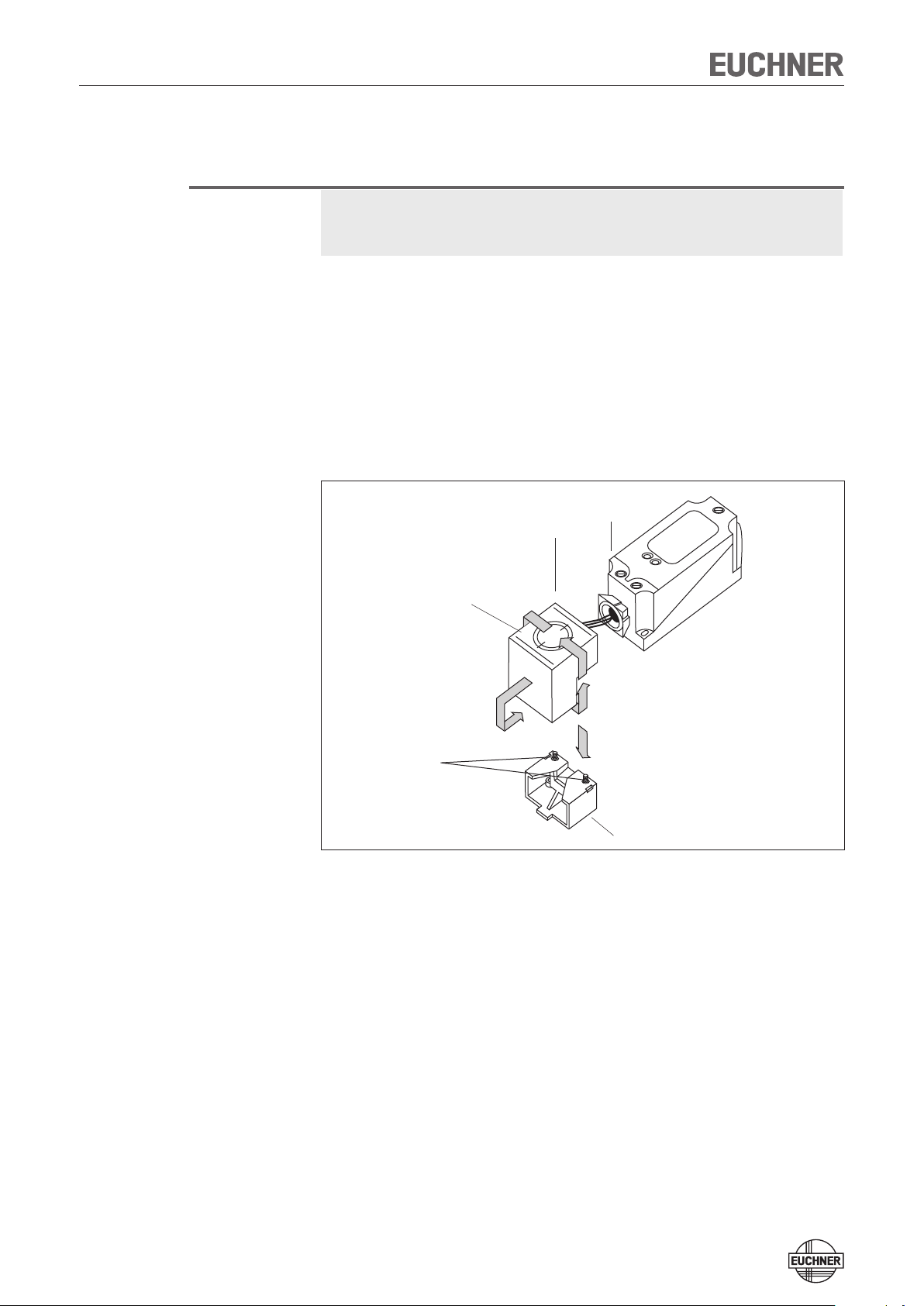
Changing the approach direction
Caution!
Risk of damage to equipment as a result of trapped cables.
Make sure that the cables are not trapped or torn off when the approach
direction is changed.
The active face of the read head can be adjusted in 5 directions. The face is marked
with the EUCHNER logo. The center of the circle corresponds to the middle of
the read head.
Remove clamp from read head by undoing the screws (1).
1.
Pull read head from the dovetail guide on the housing and rotate by 90° (ar-
2.
row A). Then place the active face on the read head in the required position by
rotating in the direction of arrow B).
Assemble in reverse order of disassembly.
3.
Active face
Read head
Evaluation unit
Clamp
Page 9
System Manual Safety System CES-A-S5H01
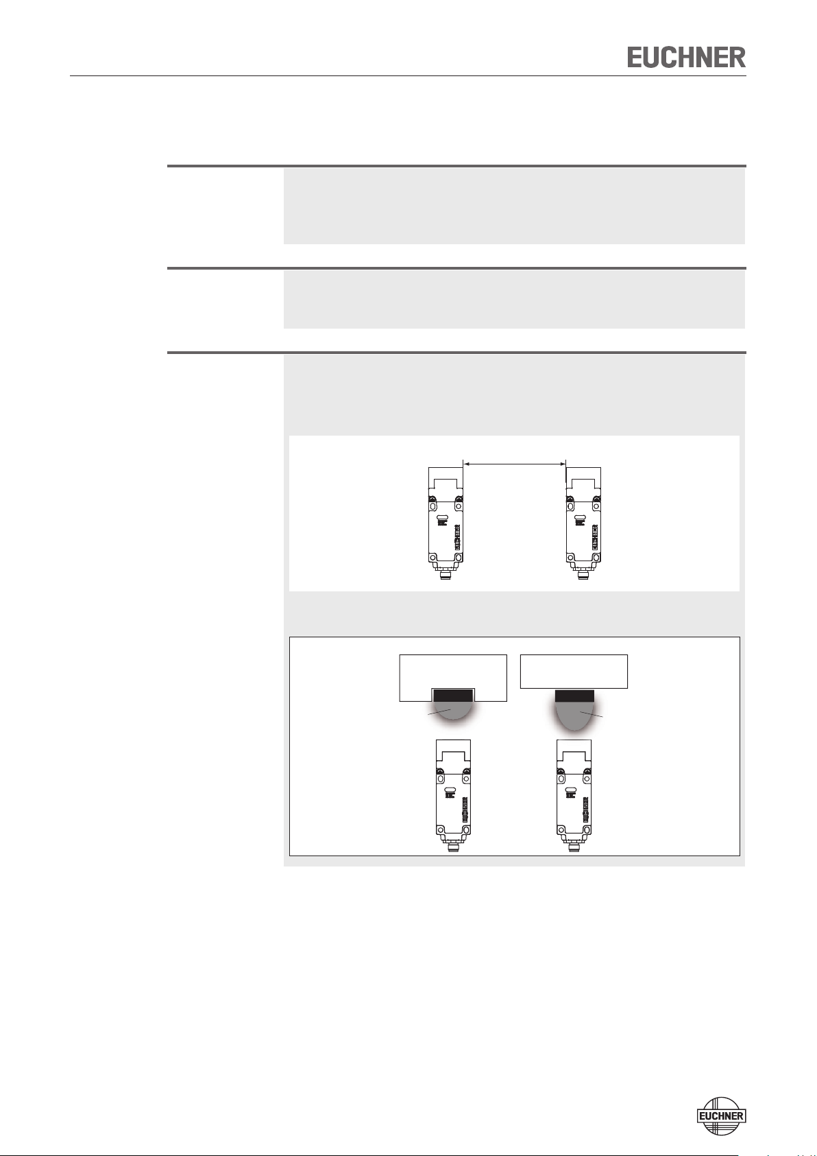
min. 80mm
Operating
distance
Actuator
Operating
distance
Actuator
Flush mounting
Surface maounting
Installation
Caution!
Safety switches must not be bypassed (bridging of contacts), turned away,
removed or otherwise rendered ineffective.
On this topic pay attention in particular to the measures for reducing the pos-
sibility of bypassing according to EN 1088:1995.A2:2008, sec. 5.7.
Caution!
Risk of damage to equipment as a result of incorrect installation. Safety switches
must not be used as a mechanical end stop.
Fit an additional end stop for the movable part of the safety guard.
Important!
From the assured switch-off distance Sar, the safety outputs are safely shut
down.
When mounting several safety switches, observe the stipulated minimum dis-
tance to avoid mutual interference.
If the actuator is installed flush, the switching distance changes as a function
of the installation depth and the safety guard material.
Note the following points:
Actuator and safety switch must be easily accessible for inspection and re-
placement.
The switching operation must only be triggered by the specific actuator desig-
nated for this purpose.
9
Page 10

System Manual Safety System CES-A-S5H01
10
Actuator and safety switch must be fitted so that
the front faces are at the minimum switch-on distance 0.8 x Sao or closer
(see section Operating distances). To avoid entering the area of possible side
lobes, a minimum distance is to be maintained in case of a side approach
direction. See section Typical operating distance for the related actuator.
when the safety guard is open up to the distance Sar (assured switch-off dis-
tance), a hazard is excluded.
the actuator is positively mounted on the safety guard, e.g. by using the
safety screws included.
they cannot be removed or tampered with using simple means.
Pay attention to the maximum tightening torque for the read head or safety
switch and actuator mountings of 1 Nm. For read heads/actuators made of
PE-HD, the maximum tightening torque is only 0.5 Nm.
Page 11

System Manual Safety System CES-A-S5H01
+UB
0 V OUT
0 V
+24 V
+LA
LA
+LB
LB
-LAB
S11
S12
S22
S21
A2
A1
CES-A-S5...
Electrical Connection
Warning!
Loss of the safety function due to incorrect connection.
Not suitable for safety relays that realize short-circuit monitoring with different
potentials (0 V/24 V). The voltage at +LA/+LB must correspond to the informa
tion in the technical data.
-
Warning!
Caution!
In case of an error, loss of the safety function through incorrect connection.
To ensure safety, both safety outputs (LA and LB) must always be evaluated.
The monitoring output OUT must not be used as a safety output.
Lay the connection cables with protection to prevent the risk of short cir-
cuits.
Risk of damage to equipment or malfunctions as a result of incorrect connection.
The inputs on an evaluation unit connected must be positive-switching, as the
two outputs on the safety switch deliver a level of +24 V in the switched-on
state.
All the electrical connections must either be isolated from the mains supply
by a safety transformer according IEC 61558-2-6 with limited output voltage
in the event of a fault, or by other equivalent isolation measures.
All electrical outputs must have an adequate protective circuit for inductive
loads. The outputs must be protected with a free-wheeling diode for this purpose.
Power devices which are a powerful source of interference must be installed
in a separate location away from the input and output circuits for signal processing. The cable routing for safety circuits should be as far away as possible from the cables of the power circuits.
If a common power supply is used, all the inductive and capacitive loads
(e.g. relay contactors) connected to the power supply must be connected to
appropriate interference suppressors.
11
Page 12

System Manual Safety System CES-A-S5H01
12
Warning!
Electrical connection may only be performed by authorized personnel trained
in EMC and with the device and wiring isolated.
The device is fully encapsulated, it is therefore not possible to remove the lid
from the housing.
Important!
If the device does not appear to function when operating voltage is applied (e.g.
green STATE LED does not illuminate or flash), the safety switch must be returned
unopened to the manufacturer.
Safety in case of faults
The operating voltage UB is reverse polarity protected.
The contacts LA/LB and -LA/-LB are short circuit-proof, however they are not
reverse polarity protected.
A short circuit between LA and LB can only be detected by external pulsing.
A short circuit in the cable can be excluded by laying the cable with protection.
The screen at the open end of the cable must also be connected electrically to
the machine ground.
Page 13

System Manual Safety System CES-A-S5H01
Safety switch CES-A-S5...
Voltage drop as a function of switching current and
cable length (examples)
Switching current Cable length "l" Voltage drop Max. voltage drop Max. voltage drop
[mA] [m] Output [V] Cable [V] Total [V]
(safety control system with
6
pulsed signals)
50
(safety relay)
400
(e. g. small contactor)
1 -100 1,4 0,1 1,5
101 - 300 1,4 0,4 1,8
1 - 15 1,5 0,2 1,7
16 - 50 1,5 0,5 2,0
51 - 100 1,5 1,0 2,5
101 - 300 1,5 3,0 3,5
1 - 15 1,7 1,2 2,9
16 - 50 1,7 4,0 5,7
51 - 100 1,7 8,0 9,7
101 - 300 1,7 - -
13
Page 14

System Manual Safety System CES-A-S5H01
14
Correct connection
Important!
To ensure safety, both safety outputs (LA and LB) must be evaluated.
To achieve category 4 according to EN ISO 13849-1, it is necessary to monitor the downstream contactors.
Warning!
In case of an error, loss of the safety function through incorrect connection.
To ensure safety, both safety outputs (LA and LB) must always be evaluated.
Single-channel use of the safety outputs leads to a reduction of the category
in accordance with EN ISO 13849-1.
M
+ 24 V
+ 24 V
+ 24 V
0 V
+U
B
OUT
-LAB
LB
+LB
LA
+LA
Monitoring output
(no safety fnction!)
Safety output LB
Safety outpu LA
To the
control system
Application
CES-A-S5...
+ 24 V
+ 24 V
+ 24 V
0 V
+U
B
OUT
-LAB
LB
+LB
LA
+LA
CES-A-S5...
M
Monitoring output
(no safety fnction!)
Safety output LB
Safety outpu LA
To the
control system
Application
Page 15

System Manual Safety System CES-A-S5H01
+24V DC
-F1
GND
Power Supply
Safety - PLC with static /
dyna mic signals
O1 Puls ed output
O2 Puls ed Output
I1 Input
I2 Input
I4 Input
I5 Input
I3 Input
I6 Input
A1
+LA
LA
+LB
LB 0V
+UB
Read he ad
2
1
4
5
EUCHNE R
CES-A-S5H-0 1
090640
D311D210D19D0
8
6
-F2
3
Connection example
CES-A-S5H-01
Important!
To achieve category 4 according to EN ISO 13849-1, it is necessary to monitor
the downstream contactors (not shown here).
This example shows only an excerpt that is relevant for connection of the CES
system. The example illustrated here does not show complete system planning.
The user is responsible for safe integration in the overall system.
15
Page 16

System Manual Safety System CES-A-S5H01
16
1
2
3
4
5
6
7
8
9
10
11
12
Pin assignment safety switch CES-A-S5...
1 LA 7 NC
2 + LA 8 D0
3
+ UB 9 D1
+ LB 10D2
4
5
LB 11 D3
6 0 V 12 NC
View of connection side of the device
The screen on the connection cable is con-
nected internally to the device screen bond-
ing clamp via the knurled nut on the M12
plug connector.
LED indicators
Reset
STATE LED green Normal operation
Flashing Teach-in operation (for further signal function
see status table)
OUT/ERROR LED yellow Valid actuator detected
LED red - Internal electronics fault
- Invalid teach-in operation
(see status table)
D0, D1, D2, D3 LED yellow Indication of the actuator number in binary
code
In case of an operating fault, the evaluation unit can be reset to the operating state
by interrupting the power supply for approx. 10 seconds.
Page 17

System Manual Safety System CES-A-S5H01
Teach-in function for actuator
The safety actuator must be allocated to the evaluation unit using a teach-in function before the system forms a functional unit. During a teach-in operation, the
safety outputs and the door monitoring output OUT are LOW, i.e. the system is in
the safe state.
Important!
Repeated teach-in of the same actuator on the same evaluation unit is not
possible.
The number of teach-in operations on one evaluation unit is limited to a maxi-
mum of 8
The evaluation unit can only be operated with the last actuator taught.
A teach-in operation is invalid if:
the teach-in operation is cancelled before the green flashing LED goes out
the power supply is switched off during the teach-in operation.
When the evaluation unit is switched on (operating voltage is applied), the
STATE LED signals the number of possible remaining teach-in operations
(see system status table).
After the eighth teach-in operation or if an "old" actuator is placed against the
read head, the system automatically switches to the teach-in mode. In both
cases, a teach-in operation with a duration of 60 seconds is started; however, the last actuator code remains active (see system status table) in the
memory – a new code is not taught.
Teach-in function for first actuator
(state on delivery)
Apply the operating voltage to the evaluation unit
1.
green LED flashes fast (approx. 4 Hz)
Move actuator to the read head (observe distance < Sao)
2.
teach-in operation starts, green LED flashes slowly (approx. 1 Hz)
Teach-in operation completed (after 60 seconds)
3.
green LED goes out
To activate the actuator code from the teach-in operation in the evaluation unit,
4.
the operating voltage must then be switched off at the evaluation unit for min.
10 seconds.
Check function of the safety guard (see section Functional check).
5.
Teach-in function for a new actuator
Apply the operating voltage to the evaluation unit
1.
Move new actuator to the read head (observe distance < Sao)
2.
teach-in operation starts, green LED flashes (approx. 1 Hz)
Teach-in operation completed (after 60 seconds)
3.
green LED goes out, new code saved, old code deactivated
To activate the new actuator code from the teach-in operation in the evaluation
4.
unit, the operating voltage must then be switched off for min. 10 seconds.
Check function of the safety guard (see section Functional check).
5.
17
Page 18

System Manual Safety System CES-A-S5H01
18
Functional check
After installation and any fault, the safety function must be fully checked. Proceed
as follows:
Warning!
Danger of fatal injury as a result of faults in installation and functional check.
Before carrying out the functional check, make sure that there are no per-
sons in the danger area.
Observe the valid accident prevention regulations.
Switch on operating voltage.
1.
The safety switch carries out a self-test.
The green STATE LED flashes up to three times.
The STATE LED then lights up continuously.
The OUT and ERROR LEDs do not light up.
Close all safety guards.
2.
The machine must not start automatically.
The green STATE LED and the yellow OUT LED light up continuously.
Enable operation in the control system.
3.
Open the safety guard.
4.
The machine must switch off and it must not be possible to start it as long as
the safety guard is open.
The green STATE LED lights up continuously; the OUT and ERROR LEDs do not
light up.
Repeat steps 2-4 for each safety guard.
Page 19

System Manual Safety System CES-A-S5H01
System Status Table
LED display
Operating mode
Actuator position
Safety outputs LA and LB
Normal operation See truth table on page 20 and section LED displays on page 16
open off 4 Hz Initial setup after delivery, ready for first teach-in operation
Setup
State indication
Fault display
closed off
closed off
X off
X off
X off
X off Device cannot perform any further teach-in operation
X off
closed off 1 x Incorrect 9th teach-in operation
3 x +
2 x +
1 x +
STATE (green)
(60 s)
OUT/ERROR (yellow)
1 Hz
State
OUT/ERROR (red)
Teach-in operation
Positive acknowledgement of completion of teach-in operation
To activate the actuator code from the teach-in operation in the evaluation unit,
the operating voltage must then be switched off at the evaluation unit for min. 3
seconds.
Indication after 1st to 5th teach-in operation
Indication of the remaining teach-in operations after the 6th teach-in operation
Indication of the remaining teach-in operations after the 7th teach-in operation
Device-internal component failure or
excessively high interference (EMC) or short circuit/external power at the LA/LB
safety output
Operating fault
Key to symbols
closed off 2 x Incorrect teach-in operation for an old actuator
closed off 3 x
N 0 Volt or not connected
1 24 Volt
0 0 Volt
15 Hz (8 s)
3 x +
3 x
X Any state
Negative acknowledgement for teach-in operation. Actuator was held in front of the
read head for less than 60 s
LED is not lit
LED is lit
LED flashes for 8 seconds with 15 Hz
LED flashes three times and then lights up continuously
LED flashes three times, and this is then repeated
Note
For monitoring outputs D0, D1, D2 and D3 see truth table on page 20
The evaluation unit can only be operated with the last actuator taught
19
Page 20

System Manual Safety System CES-A-S5H01
20
Transponder
Nr.
in the
operating
distance
Yes
No
Safety
outputs
LA, LB
ON
OFF
Position actuator
4 7 8
1
Safety actuator
Time t
200 ms
4 … 9 ms
200 ms
< 200 ms
30 … 180 ms
30 … 180 ms
Monitoring
outputs
D3
D2
D1
D0
ON
OFF
ON
OFF
ON
OFF
ON
OFF
t
t
t
t
t
If a new transponder enters the operating distance
within the switch-off delay, the switch-off delay
is interrupted and the new transponder number
signaled.
Truth table
Actuator Safety outputs Data outputs/LED displays
LA LB D3 D2 D1 D0
No actuator 0 0 0 0 0 0
Safety actuator 1 1 0 0 0 1
Actuator 2 0 0 0 0 1 0
Actuator 3 0 0 0 0 1 1
Actuator 4 0 0 0 1 0 0
Actuator 5 0 0 0 1 0 1
Actuator 6 0 0 0 1 1 0
Actuator 7 0 0 0 1 1 1
Actuator 8 0 0 1 0 0 0
Actuator 9 0 0 1 0 0 1
Actuator A 0 0 1 0 1 0
Actuator B 0 0 1 0 1 1
Actuator C 0 0 1 1 0 0
Actuator D 0 0 1 1 0 1
Actuator E 0 0 1 1 1 0
Actuator F 0 0 1 1 1 1
Pulse diagram
Page 21

System Manual Safety System CES-A-S5H01
±0,1
Ø
60
M x1
7,3
30
5,3
±0,1
7,3
23
23
46,5
119
D3 D2 D1 D0
16,5
12,5
40
40,5
+LA
LA
+LB
LB
24 V D0
+LA
LA
+LB
LB
24 V
D0
24 V
D1
24 V
D2
24 V
D3
24 V
D1
24 V
D2
24 V
D3
Technical Data
Note
If a product data sheet is included with the product, the information on the data
sheet applies in case of discrepancies with the operating instructions.
Safety switch CES-A-S5H-01
Read head and evaluation unit integrated in the standard housing
ApprovalsApprovals
Semiconductor output
M12 plug connector
Dimension drawing
Active face
LED
State
indication
LED indicator:
dog number
Switching characteristics
2 safety outputs
(semiconductor outputs)
4 data outputs for actuator
number (semiconductor
outputs, not safety output)
closed
(actuator detected)
Read head
Safety
actuator
Safety guard
(actuator not in the operating
distance)
Read head
open
Note
The data outputs D0, D1, D2, D3 have no safety function.
The safety outputs LA and LB as well as the data outputs D0, D1, D2, D3 are
short circuit-proof.
Typical operating distance
See page 24 and page 27
21
Page 22

System Manual Safety System CES-A-S5H01
22
Technical Data
Parameter
min. typ. max.
Value
Unit
Housing material Plastic PBT V0 GF30
Dimensions According to EN 60947-5-2 mm
Weight 0,4 kg
Ambient temperature at UB = DC 24 V -20 - +55 °C
Degree of protection IP67
Degree of contamination 3
Switching delay from state change
Difference time between the two safety outputs - - 120 ms
Ready delay
Dwell time
3)
4)
2)
- - 180 ms
- - 3 s
0,5 - - s
Installation position Any
Connection type M23 plug connector, 12-pin
Operating voltage UB (reverse polarity protected, regulated,
residual ripple < 5 %)
Current consumption (without load current at the data out-
put)
18 24 27 V DC
50 mA
External fuse (operating voltage UB) 0,25 - 8 A
Power supply for load U(+LA)/U(+LB) 18 - 27 V DC
Safety outputs (LA / LB, 2 semiconductor outputs, p-
switching, short circuit-proof, electrically decoupled)
- Output voltage U(LA/U(LB)
1)
HIGH U(LA) U(+LA) - 1.5 - U(+LA)
HIGH U(LB)
LOW U(LA)/U(LB)
U(+LB) - 1.5 - U(+LB) V DC
0 - 1
Switching current per safety output 1 - 400 mA
External fuse (U(+LA)/U(+LB), safety circuit 400 mA medium slow-blow
Utilization category to EN 60947-5-2 DC-13 24V 400mA
Classification according to EN 60947-5-3 PDF-M
Switching frequency - - 1 Hz
Mounting distance between 2 read heads or 2 actuators
80 - - mm
EMC protection requirements In acc. with EN 60947-5-3
Data outputs (D0, D1, D2, D3)
Semiconductor push-pull outputs short circuit-proof
- Output voltage HIGH 0.8 x U
- Output voltage LOW 0 - 2
Load current per output - - 20 mA
Ready delay
5)
B
- U
B
V DC
3 s
Switch-on delay from state change (with position actuators) 4 - 9 ms
Switch-off delay from state change (with position actuators) - 200 - ms
Relative speed with position actuators - - 2 m/s
With permissible read distance s 6 - 10 mm
Reliability figures according to EN ISO 13849-1
Category 4
Performance Level (PL) PL e
PFH
d
Mission time 20 years
1) Values at a switching current of 50 mA without taking into account the cable lengths.
2) Corresponds to the risk time according to EN 60947-5-3. This is the maximum switch-off delay for the safety outputs following removal of the actuator.
3) After the operating voltage is switched on, the safety outputs are switched off during the ready delay. The state of the data outputs is undefined during this time.
4) The dwell time of an actuator inside and outside the operating distance must be at least 0.5 s to ensure reliable detection of internal faults in the evaluation unit (self-monitoring).
5) Applying the limit value from EN ISO 13849-1:2008, section 4.5.2 (MTTF
= max. 100 years), BG certifies a PFHd of max. 2.47 x 10⁻⁸.
d
3.7 x 10⁻⁹ / h
5)
Ordering table
Series
CES-A-S5...
Typ. switch-on distance
[mm]
15 4
Category according to EN ISO
13849-1
Order no. / item
090640
CES-A-S5H-01
Page 23

System Manual Safety System CES-A-S5H01
30
±0,1
40
- 0,25
0
CES-A-BPA-098775
IP67
CD
10
4
Ø 5,2
Actuator CES-A-BPA
Cube-shaped design 40 x 40 mm
Dimension drawing CES-A-BPA
2 safety screws M4 x 14
are supplied
Active face
Active face
Technical Data
Parameter
Housing material PPS
Dimensions 40 x 40 x 10 mm
Weight 0,025 kg
Ambient temperature -25 - +70 °C
Degree of protection IP67/IP69K
Installation position Active face opposite read head
Power supply Inductive via read head
min. typ. max.
Ordering table
Series Comment Version Order no. / item
CES-A-BPA
2 safety screws M4 x 14 are supplied
Value
-
098775
CES-A-BPA
Unit
23
Page 24

System Manual Safety System CES-A-S5H01
24
45
40
35
30
25
20
15
10
-45
5
Z
Y
X
5
10
15
20
25
30
35
40
45
45
40
-45
35
30
25
20
15
10
5
Typical operating distance
Only in conjunction with actuator CES-A-BPA on surface mounting.
For a side approach direction for the actuator and read head, a minimum distance of s = 6 mm
must be maintained so that the operating distance of the side lobes is not entered.
Operating distance for center offset m = 0
Parameter
Switch-on distance - 22
Assured switch-on distance S
Switching hysteresis 1 2 -
Assured switch-off distance S
1) On surface mounting on aluminum, in a non-metallic environment the typical switching distance increases to
30 mm.
ao
ar
min. typ. max.
15 - -
- - 58
Value
Unit
1)
-
mm
Page 25

System Manual Safety System CES-A-S5H01
CES-A-B 071840
25
ø8
ø4,5
42
32
±0,1
12
4,6
Actuator CES-A-BBA
Cube-shaped design 42 x 25 mm
CES-A-BCA suitable for use in aggressive media (e.g. acids, alkalis)
ApprovalsApprovals
Technical Data
Dimension drawing CES-A-BBA
Active face Active face
2 safety screws M4 x 14
are supplied
Parameter
Housing material
- CES-A-BBA Fortron, reinforced thermoplastic, fully encapsulated
Flat seal material (CES-A-BCA only) Fluororubber 75 FPM 4100
Dimensions 42 x 25 x 12
Weight 0,02 kg
Ambient temperature
- CES-A-BBA -25 - +70
Degree of protection IP67/IP69K
Installation position
Power supply Inductive via read head
min. typ. max.
Active face opposite read head
Value
Ordering table
Series Comment Version Order no. / item
CES-A-BBA
2 safety screws M4 x 14 are supplied
-
071840
CES-A-BBA
Unit
mm
°C
25
Page 26

System Manual Safety System CES-A-S5H01
26
AB
0,1
32
±0,15
<42>
<25>
Ø 8
Ø 4,5
4,6
12
-
0
Active face
Position actuator CES-A-NBA-.
in combination with safety switch CES-A-S5H-01
ApprovalsApprovals
Technical Data
Dimension drawing
2 safety screws M4 x 14
are supplied
Parameter
Housing material Fortron, reinforced thermoplastic, fully encapsulated, green
Dimensions 42 x 25 x 12 mm
Weight 0,02
Ambient temperature -25 - +70 °C
Degree of protection IP67
Installation position Active face opposite read head
Power supply
Storage capacity 4 bits (1 BCD digit)
Data retention time (T = 22° C) approx. 20 years
min. typ. max.
Value
Inductive via read head
Ordering table
Series Actuator number Order no. / item
CES-A-NBA-2
CES-A-NBA-3
CES-A-NBA-4
CES-A-NBA-5
CES-A-NBA-6
CES-A-NBA-7
CES-A-NBA-8
CES-A-NBA-9
CES-A-NBA-A
CES-A-NBA-B
CES-A-NBA-C
CES-A-NBA-D
CES-A-NBA-E
CES-A-NBA-F
2
3
4
5
6
7
8
9
A
B
C
D
A
F
090682
CES-A-NBA-2
090683
CES-A-NBA-3
090684
CES-A-NBA-4
090685
CES-A-NBA-5
090686
CES-A-NBA-6
090687
CES-A-NBA-7
090688
CES-A-NBA-8
090689
CES-A-NBA-9
090690
CES-A-NBA-A
090691
CES-A-NBA-B
090692
CES-A-NBA-C
090693
CES-A-NBA-D
090694
CES-A-NBA-E
090695
CES-A-NBA-F
Unit
kg
Page 27

System Manual Safety System CES-A-S5H01
X
25
15
20
10
5
20
25
30
5
10
15
-30
30
-30
25
20
15
10
5
Y
Z
Typical operating distance
Only in combination with actuator CES-A-BBA or CES-A-NBA
For a side approach direction for the actuator and safety switch, a minimum distance of s = 4 mm
must be maintained so that the operating distance of the side lobes is not entered.
Value
1)
Unit
mm
1)
Unit
mm
Operating distance for center offset m = 0
Parameter
Assured switch-on distance S
ao
Switch-on distance - 20 -
Switching hysteresis 2 3 -
Assured switch-off distance S
ar
1) The values apply for surface installation of the actuator.
min. typ. max.
18 - -
- - 40
Operating distance at read distance s = 6 ... 10 mm
Parameter
Side operating point on center
offset
min. typ. max.
± 10 ± 14 -
Switching hysteresis 0,3 0,7 -
1) The values apply for surface installation of the actuator.
Value
27
Page 28

System Manual Safety System CES-A-S5H01
28
Inspection and Service
Warning!
Loss of the safety function because of damage to the device.
In case of damage, the related safety component must be replaced. The replacement of individual parts in a safety component is not permitted.
Regular inspection of the following is necessary to ensure trouble-free long-term
operation:
Check the switching function (see section Functional check)
Check the secure fastening of the devices and the connections
Check for soiling
Check for sealing of the plug connector on the safety switch
Check for loose cable connections on the plug connector.
Check of the switch-off distance
No servicing is required. Repairs to the device are only allowed to be made by
the manufacturer.
Note!
Service
The year of manufacture can be seen on the rating plate in the lower right corner.
If service support is required, please contact:
EUCHNER GmbH + Co. KG
Kohlhammerstraße 16
D-70771 Leinfelden-Echterdingen
Service telephone:
07 11 / 75 97 - 301
E-mail:
info@euchner.de
Internet:
www.euchner.de
Page 29

System Manual Safety System CES-A-S5H01
Declaration of Conformity
29
Page 30

System Manual Safety System CES-A-S5H01
30
Page 31

System Manual Safety System CES-A-S5H01
31
Page 32

More than safety.
Euchner GmbH + Co. KG
Kohlhammerstraße 16
D-70771 Leinfelden-Echterdingen
info@euchner.de
www.euchner.de
Issue:
095710-08-01/12
Title:
System Manual Safety System CES-A-S5H-01
(Translation of the Original Operating Instructions)
Copyright:
© EUCHNER GmbH + Co. KG, 01/2012
Subject to technical modifications; no responsibility
is accepted for the accuracy of this information.
 Loading...