

Page 1

Operating Instructions
Non-Contact Safety Switch
CES-AR-CR2-AH (Unicode)
CES-AR-CL2-AH (Unicode)
More than safety.
Page 2

Operating Instructions Safety Switches CES-AR-C.2-AH
Contents
Correct use 3
Possible combinations for CES components 4
Exclusion of liability and warranty 5
General safety instructions 5
Function 6
Mounting 8
Electrical connection 9
Safety in case of faults 10
Fuse protection for power supply 10
Requirements for connection cables 11
Maximum cable lengths 12
Connector assignment of safety switch CES-AR 14
Connection of a single CES-AR-C 15
Connection of several CES-AR-C in a switch chain 17
Notes for operation with safe control systems 19
Setup 21
LED indicators 21
Teach-in function for actuator 21
Functional check 23
System status table 24
Technical data 25
Technical data for safety switch CES-AR-CR2-AH/CES-AR-CL2-AH 25
Technical data for actuator CES-A-BLN-... 29
Technical data for actuator CES-A-BDN-06 31
Ordering information and accessories 32
Inspection and service 33
Service 33
Declaration of conformity 34
2
Page 3

Operating Instructions Safety Switches CES-AR-C.2-AH
Correct use
The Coded Electronic Safety switches series CES are safety devices for monitoring movable safety guards.
In combination with a separating safety guard and the machine control, this safety
component prevents dangerous machine movements from occurring while the
safety guard is open. A stop command is triggered if the safety guard is opened
during the dangerous machine function.
Before safety switches are used, a risk assessment must be performed on the
machine, e.g., in accordance with:
Ì EN ISO 13849-1, Safety of machinery. Safety related parts of control systems.
General principles for design
Ì EN ISO 12100, Safety of machinery – General principles for design – Risk as-
sessment and risk reduction
Ì IEC 62061, Safety of machinery. Functional safety of safety-related electrical,
electronic and programmable electronic control systems.
Correct use includes compliance with the relevant requirements for installation
and operation, for example
Important!
Ì EN ISO 13849-1, Safety of machinery. Safety related parts of control systems.
General principles for design
Ì EN 1088, Safety of machinery. Interlocking devices associated with guards.
Principles for design and selection
Ì EN 60204-1, Safety of machinery. Electrical equipment of machines. General
requirements
Ì EN 60947-5-3, Specification for low-voltage switchgear and controlgear. Con-
trol circuit devices and switching elements. Requirements for proximity devices
with defined behaviour under fault conditions
The safety switch must be used only in conjunction with the designated CES actuators from EUCHNER. On the use of different actuators, EUCHNER provides no
warranty for safe function.
Several devices are only allowed to be connected in series using devices intended
for series connection with the CES-AR. Check the operating instructions for the
related device. A combination of other CES devices or devices from other manufacturers is not allowed.
A maximum of 20 safety switches are allowed to be operated in a switch chain.
Ì The user is responsible for the integration of the device into a safe overall
system. For this purpose, the overall system must be validated, e.g. in accordance with EN ISO 13849-2.
Ì Correct use requires observing the permissible operating parameters (see
Technical data).
Ì If a product data sheet is included with the product, the information on the
data sheet applies in case of discrepancies with the operating instructions.
Ì In the estimation of the PL for the overall system, a maximum value of
100 years can be assumed for the MTTFd according to the limit value in
EN ISO 13849-1:2008, section 4.5.2. This corresponds to a minimum value
for the PFHd of 2.47x10⁻⁸/h.
Ì When up to 11 devices are connected in series, these limit values can be
assumed for the entire switch chain as a subsystem. As a subsystem, this
switch chain achieves PL e.
3
Page 4
Operating Instructions Safety Switches CES-AR-C.2-AH
Important!
Safety switch
Door hinge right
CES-AR-CR2-AH
Door hinge left
CES-AR-CL2-CH
Ì In the case of series connection of more than 11 devices, the PFH
calculated according to one of the stated methods in EN ISO 13849-1:2008,
Section 4.5.1.
Ì If the simplified method according to Section 6.3 of EN ISO 13849:2008-12
is used for validation, the Performance Level (PL) might be reduced when
more than 11 devices are connected in series.
Ì It is only allowed to use components that are permissible in accordance with
the table below.
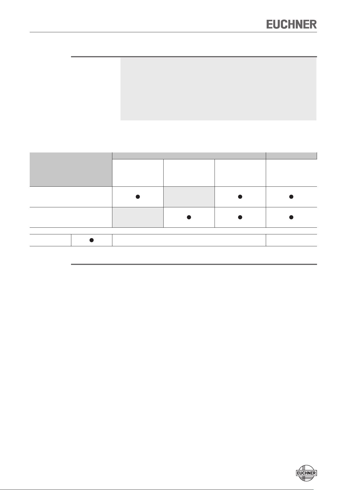
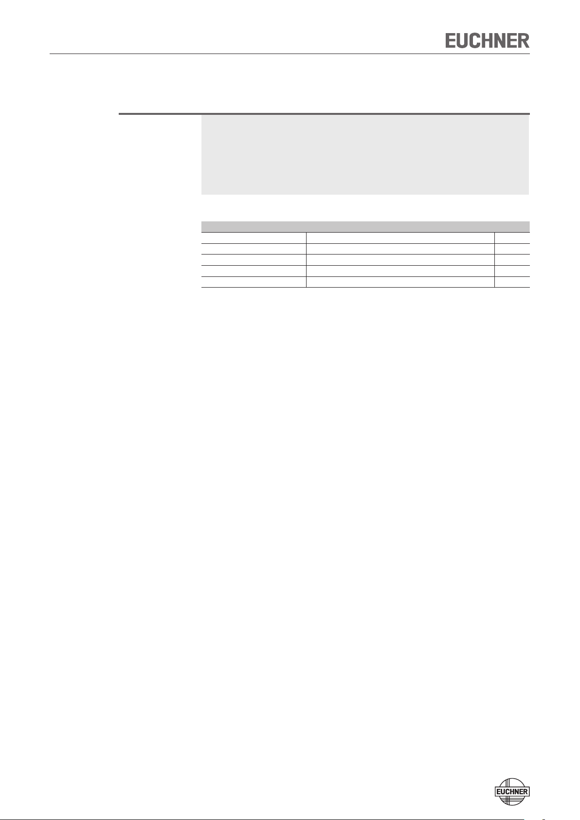
Possible combinations for CES components
Actuator
Door hinge right
CES-A-BLN-R2-100776
100776
Door hinge left
CES-A-BLN-L2-104510
104510
Usage independent of
position of door hinge
CES-A-BLN-U2-103450
103450
Usage independent of
position of door hinge
CES-A-BDN-06-104730
104730
can be
d
Key to symbols
Combination possible
Note!
Devices with version number V 1.1.2 or higher can be operated on an AR evaluation unit. Please refer to the operating instructions for the relevant AR evaluation
unit for more information.
4
Page 5
Operating Instructions Safety Switches CES-AR-C.2-AH
Exclusion of liability and warranty
In case of failure to comply with the conditions for correct use stated above, or
if the safety instructions are not followed, or if any servicing is not performed as
required, liability will be excluded and the warranty void.
General safety instructions
Safety switches fulfill personal protection functions. Incorrect installation or tampering can lead to fatal injuries to personnel.
Check the safe function of the safety guard particularly
Ì after any setup work
Ì after the replacement of a CES component
Ì after an extended period without use
Ì after every fault
Independent of these checks, the safe function of the safety guard should be
checked at suitable intervals as part of the maintenance schedule.
Warning!
Important!
Danger of fatal injury in the event of incorrect connection or incorrect use.
Ì Safety switches must not be bypassed (bridging of contacts), turned away,
removed or otherwise rendered ineffective.
On this topic pay attention in particular to the measures for reducing the possibility of bypassing from EN 1088:1995+A2:2008, Section 5.7.
The device is only allowed to be installed and placed in operation by authorized
personnel
Ì who are familiar with the correct handling of safety components
Ì who are familiar with the applicable EMC regulations
Ì who are familiar with the applicable regulations on health and safety and ac-
cident prevention
Ì who have read and understood the operating instructions.
Prior to use, read the operating instructions and keep these in a safe place.
Ensure that the operating instructions are always available during mounting,
setup and servicing work. EUCHNER cannot provide any warranty in relation to
the readability of the CD for the storage period required. For this reason you
should archive a printed copy of the operating instructions. You can download
the operating instructions from www.EUCHNER.de.
5
Page 6

Operating Instructions Safety Switches CES-AR-C.2-AH
Function
The device meets the following safety requirements:
Ì Category 4, PLe according to EN ISO 13849-1
Ì Redundant design of the circuit in the unit with self-monitoring
Ì This means that the safety system still functions even if an internal component
fails
Ì The switch state of the semiconductor outputs is continuously monitored inter-
nally
Ì Short circuit detection at the safety outputs by pulsed signals
The following switch-on condition applies to safety outputs OA and OB (see also
System status table and the section Typical system times):
Ì Safety guard closed
Ì Both safety outputs (IA and IB) must be on
The system consists of the following components: coded actuator (transponder)
and switch.
Each actuator has a unique electronic coding and is therefore a unique element.
The code in an actuator cannot be reprogrammed.
The actuator must be assigned to the safety switch by a teach-in process so that
it is detected by the system. This unambiguous assignment ensures a particularly
high level of protection against tampering.
The safety switch is fastened to the fixed part of the safety guard.
The actuator attached to the movable part of the safety guard is moved towards
the read head fitted in the safety switch by closing the door. When the switch-on
distance is reached, power is supplied to the actuator by the read head by induction and data can be transferred.
The bit pattern read is compared with the code saved in the safety switch. If the
data match, the safety outputs are enabled.
Due to the combination of dynamic polling of the actuator and the redundant,
diverse design of the safety electronics with the two feedback safety outputs, the
safety switch will enter the safe state with every detectable fault.
When the safety guard is opened, the safety outputs switch off the safety circuit
and the monitoring output OUT is switched off. The state of the safety outputs is
monitored internally by two microprocessors.
If faults are detected, the safety circuit is switched off and the DIA LED illuminates.
In case of devices with a DIA monitoring output, the output is switched on.
The safety switch has a redundant circuit design with self-monitoring. This means
that the safety system is still effective even if a component fails.
The system is designed so that failures will not result in the loss of the safety function. The occurrence of failures is detected by cyclic self-monitoring at the latest
on the next demand to close the safety contacts (e.g. on starting).
6
Page 7

Operating Instructions Safety Switches CES-AR-C.2-AH
If the safety door with the actuator should settle over time, the actuator can drift
out of the read head operating distance. The device recognizes this and indicates
that the actuator is in the boundary area (function available for V 1.1.2 and higher).
This allows the safety door to be readjusted in time.
7
Page 8
Operating Instructions Safety Switches CES-AR-C.2-AH
Mounting
Caution!
Safety switches must not be bypassed (bridging of contacts), turned away,
removed or otherwise rendered ineffective.
Ì On this topic pay attention in particular to the measures for reducing the pos-
sibility of bypassing according to EN 1088:1995.A2:2008, sec. 5.7.
Caution!
Risk of damage to equipment as a result of incorrect installation. Safety switches
must not be used as a mechanical end stop.
Ì Fit an additional end stop for the movable part of the safety guard.
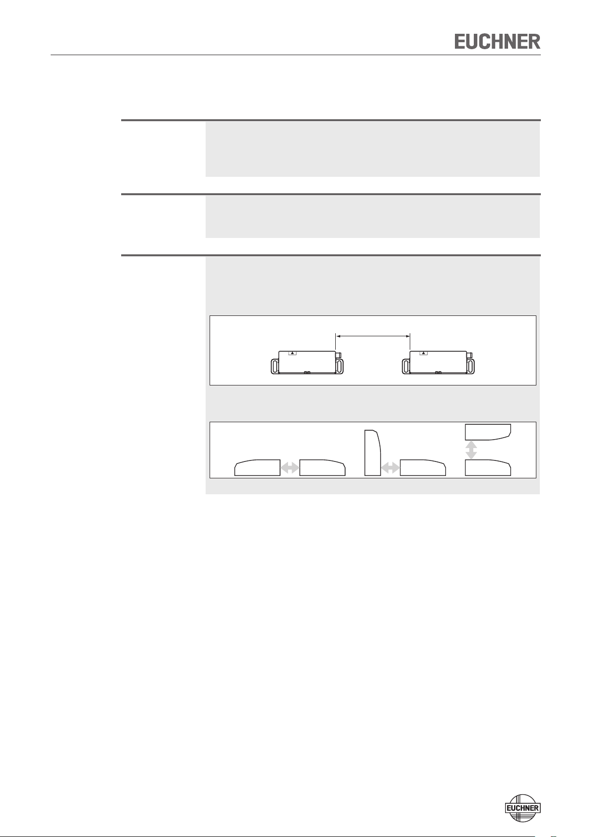
Important!
Ì From the assured switch-off distance S
down.
, the safety outputs are safely shut
ar
Ì When mounting several safety switches, observe the stipulated minimum
distance to avoid mutual interference.
min. 120 mm
Ì The operating distance changes during the mounting of the actuator as a
function of the material used for the safety guard.
Note the following points:
Ì Actuator and safety switch must be easily accessible for inspection and re-
placement.
Ì The switching operation must only be triggered by the specific actuator desig-
nated for this purpose. For permissible combinations please see the Table Pos-
sible combinations for CES components on page 4.
Ì Actuator and safety switch must be fitted so that
Ì the front faces are at the minimum switch-on distance 0.8 x S
when the safety guard is closed (see section Operating distances). A minimum distance dependent on the actuator must be maintained for a side approach direction: - For CES-A-BLN-R2 6 mm
- For CES-A-BLN-L2 6 mm
- For CES-A-BLN-U2 6 mm
- For CES-A-BDN-06 8 mm
Ì when the safety guard is open up to the distance S
tance), a hazard is excluded.
(assured switch-off dis-
ar
or closer
ao
Ì the actuator is positively mounted on the safety guard, e.g. by using the
safety screws included.
Ì they cannot be removed or tampered with using simple means.
Ì Pay attention to the maximum tightening torque for the safety switch and
actuator mountings of 1 Nm.
8
Page 9
Operating Instructions Safety Switches CES-AR-C.2-AH
Electrical connection
The following connection options are available:
Ì Separate operation
Ì Series connection with Y-distributors from EUCHNER (only with M12 plug con-
nector)
Ì Series connection, e. g. with wiring in the control cabinet
Ì Operation on an AR evaluation unit.
Warning!
In case of an error, loss of the safety function through incorrect connection.
Ì To ensure safety, both safety outputs (OA and OB) must always be evaluated.
Ì The monitoring output OUT must not be used as a safety output.
Ì Lay the connection cables with protection to prevent the risk of short cir-
cuits.
Caution!
Risk of damage to equipment or malfunctions as a result of incorrect connection.
Ì Do not use a control system with pulsing or switch off the pulsing function in
your control system. The device generates its own pulse signal on the output lines OA/OB. A downstream control system must tolerate these pulses,
which may have a length of up to 1 ms.
The pulses are also output when the safety outputs are switched off.
Depending on the inertia of the connected device (control system, relay,
etc.), this can lead to short switching processes.
Ì The inputs on an evaluation unit connected must be positive-switching, as the
two outputs on the safety switch deliver a level of +24 V in the switched-on
state.
Ì All the electrical connections must either be isolated from the mains supply by
a safety transformer according to IEC 61558-2-6 with limited output voltage in
the event of a fault, or by other equivalent isolation measures (PELV).
Ì For use and operation as per the requirements, a power supply with the
feature "for use in class 2 circuits" must be used. The same requirement applies to the safety outputs.
Alternative solutions must comply with the following requirements:
a) Electrically isolated power supply unit with a max. open-circuit voltage of 30
V/DC and a limited current of max. 8 A.
b) Electrically isolated power supply unit in combination with fuse as per UL248.
This fuse should be designed for max. 3.3 A and should be integrated into
the 30 V/DC voltage section.
Ì For use and applications as per the requirements of , a connection cable
listed under the UL category code CYJV2 must be used and the following
requirements met: The connection cables of EUCHNER meet these requirements. The same requirement applies to the safety outputs.
Ì All electrical outputs must have an adequate protective circuit for inductive
loads. The outputs must be protected with a free-wheeling diode for this purpose. RC interference suppression units must not be used.
* Note on the scope of the UL approval: Only for applications as per NFPA 79 (Industrial Machinery)
The devices are tested according to the requirements of UL508 (protection against electric shock and fire).
9
Page 10
Operating Instructions Safety Switches CES-AR-C.2-AH
Caution!
Ì Power devices which are a powerful source of interference must be installed
in a separate location away from the input and output circuits for signal processing. The cable routing for safety circuits should be as far away as possible from the cables of the power circuits.
Ì In order to avoid EMC interference, the physical environmental and operating
conditions at the installation site of the device must comply with the requirements according to the standard EN 60204-1:2006, section 4.4.2 (EMC).
Ì Please pay attention to any interference fields in case of devices such as
frequency converters or induction heating systems. Observe the EMC instructions in the manuals from the respective manufacturer.
Important!
If the device does not appear to function when operating voltage is applied (e.g.
green STATE LED does not flash), the safety switch must be returned unopened
to the manufacturer.
Safety in case of faults
Ì The operating voltage U
is reverse polarity protected.
B
Ì The contacts OA/OB are short circuit-proof
Ì A short circuit between OA and OB is detected by the switch.
Ì A short circuit in the cable can be excluded by laying the cable with protection.
Fuse protection for power supply
The power supply must be provided with fuse protection depending on the number
of switches and current required for the outputs. The following rules apply:
Max. current consumption of an individual switch I
I
= IUB + I
max
= Switch operating current (50 mA)
I
UB
= Monitoring output load current (max. 50 mA)
I
OUT
= Load current of safety outputs OA + OB (2 x max. 200 mA)
I
OA+OB
OUT
+ I
OA+OB
Max. current consumption of a switch chain Σ I
Σ I
max
= I
+ n x (IUB + I
OA+OB
OUT
)
n = Number of connected switches
max
max
10
Page 11
Operating Instructions Safety Switches CES-AR-C.2-AH
Requirements for connection cables
Caution!
Risk of damage to equipment or malfunctions as a result of incorrect connection cables.
Ì Use connection components and connection cables from EUCHNER
Ì On the usage of other connection components, the requirements in the fol-
lowing table apply. EUCHNER provides no warranty for safe function in case
of failure to comply with these requirements.
Observe the following requirements with respect to the connection cables:
Parameter Value Unit
Conductor cross-section min. 0.34 mm²
R max. 60 W/km
C max. 120 nF/km
L max. 0.65 mH/km
Recommended cable type LIYY 8x or 5x 0.34 mm²
11
Page 12

Operating Instructions Safety Switches CES-AR-C.2-AH
Maximum cable lengths
Switch chains are permitted up to a maximum overall cable length of 200 m taking
into account the voltage drop as a result of the cable resistance (see table below
with example data and case example).
l
=200 m
max
l
SPS
PLC
u
= 24 V -10%
min
l
1
l
n
i
out
2
un = 24 V -20%
5 x 0,34 mm
oder
5 x 0,14 mm
n
Max. number of
switches
5
6
10
2
2
5 x 0,34 mm
DIA
STATE
2
DIA
STATE
5 x 0,34 mm
CES-AR # n CES-AR # n-1 CES-AR # 1
l1 (m)
I
(mA)
out
Possible output current per channel
OA/OB
10 70 140
25 50 110
50 35 80
100 25 50
200 13 25
10 60 120
25 50 90
50 35 70
100 20 50
200 13 25
10 35 70
25 30 60
50 25 50
100 15 35
200 10 20
Max. cable length from the last switch
to the control system with conductor
cross-section
0.14 mm² 0.34 mm²
2
DIA
STATE
Important!
The cables between the Y-distributors must have a conductor cross-section of
0.34 mm².
12
Page 13

Operating Instructions Safety Switches CES-AR-C.2-AH
Determining cable lengths using the example table
Example: 6 switches are to be used in series. Cabling with a length of 40 m is
routed from a safety relay in the control cabinet to the last switch (#6) (conductor cross-section 0.34 mm²). Cables with a length of 20 m each are connected
between the individual CES-AR safety switches.
= 140 m
l
max
l
= 5 x 20 m
2
Sicherheitsrelais
Safety Relay
l1 = 40 m
i
= min. 75 mA
out
l
= 20 m
n
un = min. 19,2 V
CES-AR # 6
DIA
STATE
DIA
STATE
CES-AR # 5 CES-AR # 4 CES-AR # 3
DIA
STATE
DIA
STATE
DIA
STATE
CES-AR # 2 CES-AR # 1
DIA
STATE
Fig. 1: Circuit example with six CES-AR
A safety relay is connected downstream which consumes 75 mA at each of the
two safety inputs. This operates over the whole temperature range with a voltage
of 19.2 V (corresponds to 24 V -20%).
All the relevant values can now be determined using the example table:
1. Select the corresponding section in the column n (max. number of switches).
Here: 6 switches.
1. In column I
(possible output current per channel OA/OB), find a current
out
greater than or equal to 75 mA. Here: 100 mA.
¨ It is then possible to determine the maximum cable length from the last switch
(#6) to the control system from column l
. Here: a length of 50 m is permissible
1
with a conductor cross-section of 0.34 mm².
Result: The desired cable length l
table. The overall length of the switch chain l
of 40 m is below the permitted value from the
1
of 140 m is less than the maximum
max
value of 200 m.
13
Page 14

Operating Instructions Safety Switches CES-AR-C.2-AH
1
7
6
5
4
3
2
8
8
2
7
6
1
3
4
5
UB
0V
IA
IB
OA
OB
OUT
RST
Connector assignment of safety switch CES-AR
Coding lug
View on the connection side of the safety switch
Fig. 2: Connector assignment of safety switch CES-AR
Pin Designation Description Wire color
1 IB Enable input for channel 2 white
2 UB Power supply, DC 24 V brown
3 OA Safety output, channel 1 green
4 OB Safety output, channel 2 yellow
5 OUT Door monitoring output gray
6 IA Enable input for channel 1 pink
7 0V Ground, DC 0 V blue
8 RST Reset input red
14
Page 15

Operating Instructions Safety Switches CES-AR-C.2-AH
Connection of a single CES-AR-C
If a single CES-AR-C is used, connect the switch as shown in Figure 3. The OUT
output can also be connected here to a control system as a monitoring output.
The switch can be reset via the RST input. To do this, a voltage of 24 V is applied
to the RST input for at least 3 seconds. The RST input must be connected to 0 V
if it is not used.
Important!
The subsystem CES-AR complies with PL e in accordance with EN 13849-1. To
integrate the subsystem in a category 3 or 4 structure, it is necessary to monitor
the downstream load (the feedback loop must be monitored).
These examples show only an excerpt that is relevant for connection of the CES
system. The example illustrated here does not show complete system planning.
The user is responsible for safe integration in the overall system.
DC 24 V
IB1
WH
UB2
BN
OA3
GN
OB4
YE
OUT5
GY
IA6
PK
0V7
BU
RST8
RD
-K1
Plug connector (8-pin)
CES-AR-C #1
GND
Fig. 3: Connection example for a single CES-AR-C
A1
A2
-K2
13
14
A1
13
A2
14
M
-M1
15
Page 16

Operating Instructions Safety Switches CES-AR-C.2-AH
Warning!
In case of an error, loss of the safety function through incorrect connection.
Ì To ensure safety, both safety outputs (OA and OB) must always be evaluated.
Single-channel use of the safety outputs leads to a loss of the category in
accordance with EN ISO 13849-1.
DC 24 V
IB1
WH
UB2
BN
OA3
GN
OB4
YE
OUT5
GY
IA6
PK
0V7
BU
RST8
RD
-K1
Plug connector (8-pin)
CES-AR-C #1
GND
Fig. 4: Example of incorrect connection.
A1
A2
-K2
13
14
A1
A2
M M
-M1 -M2
13
14
16
Page 17

Operating Instructions Safety Switches CES-AR-C.2-AH
Connection of several CES-AR-C in a switch chain
Important!
Ì An AR switch chain may contain a maximum of 20 safety switches.
Ì In the estimation of the PL for the overall system, a maximum value of 100
years can be assumed for the MTTF
13849-1:2008, section 4.5.2. This corresponds to a minimum value for the
PFHd of 2.47x10⁻⁸/h.
Ì When up to 11 devices are connected in series, these limit values can be
assumed for the entire switch chain as a subsystem. As a subsystem, this
switch chain achieves PL e.
Ì In the case of series connection of more than 11 devices, the PFH
calculated according to one of the stated methods in EN ISO 13849-1:2008,
Section 4.5.1.
Ì If the simplified method according to Section 6.3 of EN ISO 13849:2008-12
is used for validation, the Performance Level (PL) might be reduced when
more than 11 devices are connected in series.
The series connection is shown here based on the example of the version with plug
connectors M12. The switches are connected one behind the other with the aid
of pre-assembled connection cables and Y-distributors. If a safety door is opened
or if a fault occurs on one of the switches, the system shuts down the machine. A
higher level control system cannot, however, detect which safety door is open or
on which switch a fault has occurred with this connection technology. A special AR
evaluation unit is required for this purpose (see section Information on operation
on an AR evaluation unit).
according to the limit value in EN ISO
d
can be
d
The series connection can also be realized via additional terminals in a control
cabinet.
The safety outputs are permanently assigned to the respective safety inputs of the
downstream switch. OA must be connected to IA and OB to IB. If the connections
are interchanged (e.g. OA to IB), the unit will switch to fault state
Always use input RST in series connections. All switches in a chain can be reset at
the same time with this reset input. To do this, a voltage of 24 V must be applied
to the RST input for at least 3 seconds. If input RST is not used in your application,
it should be connected to 0 V.
Note the following on this aspect:
Ì A common signal must be used for all switches in the chain. This can be a
changeover switch or the output of a control system. A button is not suitable
because Reset must always be connected to GND during operation (see switch
S11 in Figure 5).
Ì Reset must always be performed simultaneously for all switches of the chain.
Information on operation on an AR evaluation unit
Devices with version number V 1.1.2 or higher can be operated on an AR evaluation unit. Please refer to the operating instructions for the relevant AR evaluation
unit for more information.
17
Page 18

Operating Instructions Safety Switches CES-AR-C.2-AH
0V
24V
12
-S1
11 14
Eval Unit
OB
4
OA
3
Safety Outputs
OUT
5
0V
7
UB
2
RST
8
IA
6
IB
1
Safety Inputs
Read Head
Y-distributor
RST
5
RST
UB
1
135
UBOA0V
IA0VIB
OB
2
4
3
OB
OA
OUT
Y-distributor Y-distributor
0V
UB
RST
IA
IB
1 6 2 78 5 3 4
2
4
OB
Y-distributor
OA
OUT
0V
UB
RST
IA
IB
OB
OA
OUT
0V
UB
RST
IA
IB
4
3
Safety Outputs
5
7
2
8
6
1
Safety InputsSafety Inputs
4
3
Safety Outputs
5
7
2
8
6
1
Read Head
CES CES CES
Read Head
Terminating plug
2
4
1UB
Terminating plug
IA
IB
Fig. 5: Connection example for series connection with reset and changeover switch
18
Page 19

Operating Instructions Safety Switches CES-AR-C.2-AH
Notes for operation with safe control systems
Important!
Devices with start button and feedback loop are not suitable for connection to
safe control systems.
Please observe the following requirements for connection to safe control systems:
Ì Use a common power supply for the control system and the connected safety
switches.
Ì A clocked power supply must not be used for UB. Tap the supply voltage
directly from the power supply unit. If the supply voltage is connected to a
terminal of a safe control system, this output must provide sufficient electrical
current.
Ì Always connect inputs IA and IB directly to a power supply unit or to outputs
OA and OB of another EUCHNER AR device (series connection). Pulsed signals
must not be present at inputs IA and IB.
Ì Outputs OA and OB can be connected to the safe inputs of a control system.
Prerequisite: The input must be suitable for pulsed safety signals (OSSD signals, e.g. from light curtains). The control system must tolerate pulses on the
input signals. This normally can be set up by parameter assignment in the
control system. Observe the notes of the control system manufacturer. For the
pulse duration of your safety switch, please refer to the section Typical system
times on page 26.
A detailed example of connecting and setting the parameters of the control
system is available for many devices at www.euchner.de in the download area »
Applikationen » CES. The features of the respective device are dealt with there in
greater detail.
19
Page 20

Operating Instructions Safety Switches CES-AR-C.2-AH
24V
0V
M
3
DC24V
2
PWR
Supply of
the control
DI4 DI0DO..M DO..P DO
4/8 F-DI4 F-DO
Digital
Output
-X1 -X1
ET200
0V(UCM)
X2:1
J
X2:5
UCM
X2:4
LED1
X2:3
OB
4
OA
3
Safety Output
OUT
5
0V
7
UB
2
RST
8
IA
6
Safety Inputs
IB
1
OB
4
OA
3
Safety Output
OUT
5
0V
7
UB
Y-distributor Y-distributor
2
RST
8
IA
6
IB
Safety InputsSafety Inputs
1
CET
CES
Read Head
OB
4
OA
3
Safety Output
OUT
Y-distributor
Terminating plug
5
0V
7
UB
2
RST
8
IA
6
IB
1
CES
Read Head
Fig. 6: Connection example for mixed series connection (2 x CES and 1 x CET)
on ET200
20
Page 21

Operating Instructions Safety Switches CES-AR-C.2-AH
Setup
LED indicators
LED Color State Significance
Important!
illuminated
STATE
DIA
green
red
flashing
illuminated
Teach-in function for actuator
The actuator must be allocated to the safety switch using a teach-in function before
the system forms a functional unit.
During a teach-in operation, the safety outputs and the monitoring output OUT are
in a high-resistance state, i.e. the system is in the safe state.
Normal operation
- Teach-in operation or Power Up
- Actuator in boundary area (V. 1.1.2 or higher
(further signal functions: see status table)
- Internal electronics fault
- Fault at the inputs/outputs
Ì The safety switch disables the code of the previous actuator if teach-in is
carried out for a new actuator. Teach-in is not possible again immediately for
this actuator if a new teach-in operation is carried out. The disabled code is
released again in the safety switch only after a third code has been taught.
Ì The safety switch can only be operated with the last actuator taught.
Ì If the switch detects the actuator that was most recently taught when in
teach-in standby state, this state is ended immediately and the switch changes to normal state.
Ì The actuator being taught is not activated if it is within the operating dis-
tance for less than 60 s.
Actuator teach-in
1. Apply operating voltage to the safety switch.
¨ The green LED flashes quickly (approx. 10 Hz).
A self-test is performed during this time (approx. 8 s). After this, the LED
flashes cyclically three times and signals that it is in standby state for teachin.
Standby state for teach-in remains active for approx. 3 minutes.
2. Move new actuator to the read head (observe distance < S
¨ Teach-in operation starts, green LED flashes (approx. 1 Hz). During teach-in,
the safety switch checks whether the actuator is a disabled actuator. If this is
not the case, the teach-in operation is completed after approx. 60 seconds,
the green LED goes out. The new code has been saved, the old code disabled.
).
ao
3. To activate the new actuator code from the teach-in operation in the safety
switch, the operating voltage to the safety switch must then be switched off
for min. 3 seconds.
21
Page 22

Operating Instructions Safety Switches CES-AR-C.2-AH
Teach-in function for series connection
It is recommended not to teach in the actuators in the series connection but to
teach them in one by one instead. Teach-in in a series connection works analogously to individual operation in principle. All switches in the chain can be taught
in at the same time. The prerequisite is that the switch chain functions without
errors and the following
steps are complied with. Further steps might have to observed for mixed switch
chains (e.g. for chains with CES and safety switches with guard locking). Observe
the operating instructions for the other devices in the chain for this purpose.
Proceed as follows:
1. Mount the switches and actuators and fully connect them (see e. g. Figure 5
or Figure 6)
2. Close all safety doors in the chain.
3. Switch on the power supply.
¨ The green LED STATE flashes at approx. 1 Hz on the safety switches and the
associated actuators are taught in. This happens for approx. 1 minute. Do not
switch off during this time and do not actuate reset! The teach-in operation has
ended when all LEDs on the safety switches are off.
4. Actuate the reset for at least 3 s (24 V on RST)
¨ The system restarts and then functions in normal operation.
Replacing and teaching-in device
Work on the wiring (e.g. during device replacement) generally should be performed
in a de-energized state. On certain systems, it is nevertheless necessary to perform
this work and subsequent teach-in during ongoing operation.
Input RST must be connected as shown in Figure 5 to permit this.
Proceed as follows:
1. Open the safety door on which the switch or actuator is to be replaced.
2. Mount the new switch or actuator and fully connect them.
3. Close all safety doors in the chain.
4. Actuate the reset for at least 3 s (24 V on RST).
¨ On the safety switch that is positioned at a new actuator, the green LED flashes
at approx. 1 Hz and the actuator is taught-in. This happens for approx. 1 minute - do not switch off during this time and do not actuate reset! The teach-in
operation has ended when all LEDs on the device are off.
5. Actuate the reset for at least 3 s (24 V on RST).
¨ The system restarts and then continues to function in normal operation.
22
Page 23

Operating Instructions Safety Switches CES-AR-C.2-AH
Functional check
After installation and any fault, the safety function must be fully checked. Proceed
as follows:
Warning!
Danger of fatal injury as a result of faults in installation and functional check.
Ì Before carrying out the functional check, make sure that there are no per-
sons in the danger area.
Ì Observe the valid accident prevention regulations.
1. Switch on operating voltage.
Ì The safety switch carries out a self-test.
The green LED STATE flashes for 8 s with 10 Hz.
The STATE LED then flashes at regular intervals.
2. Close all safety guards.
Ì The machine must not start automatically.
Ì The green STATE LED illuminates continuously.
3. Enable operation in the control system.
4. Open the safety guard.
Ì The machine must switch off and it must not be possible to start it as long as
the safety guard is open.
Ì The green LED STATE flashes at regular intervals.
Repeat steps 2-4 for each safety guard.
23
Page 24
Operating Instructions Safety Switches CES-AR-C.2-AH
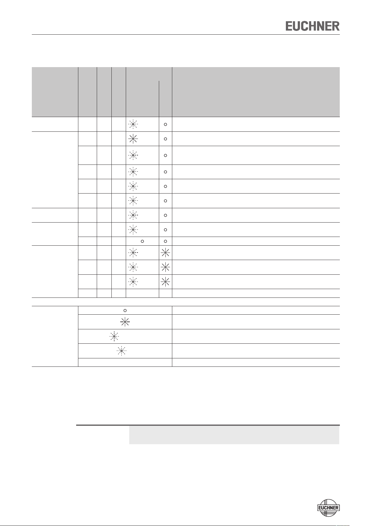
System status table
LED indicator
output
Operating mode
Self-test
Normal operation
Teach-in standby
Setup
Fault display
Actuator/
door position
Safety outputs
OA and OB
X off off
closed On On
closed On On
closed off On
open off off
open off off
open off off
closed off off
X off off
X off off
X off off
X off off
Monitoring output
OUT
STATE (green)
10 Hz
(8 s)
flashes
quickly
2 Hz
1 x
inverse
1 x Normal operation, door open
2 x Normal operation, door open, no actuator taught
3 x Door open, unit is ready for teach-in for another actuator (only short time after power-up)
1 Hz Teach-in operation
2 x
4 x Output fault (e. g. short circuits, loss of switching ability)
5 x Internal fault (e.g. component faulty, data error)
State
DIA (red)
Self-test after power up
Normal operation, door closed
Normal operation, door closed, actuator in the boundary area ¨ Re-adjust door (V. 1.1.2
or higher)
Normal operation, door closed, preceding device in the switch chain signals "door open"
(only with series connection)
Positive acknowledgment after completion of teach-in operation
Input fault (e. g. missing test pulses, illogical switch state from previous switch in the
switch chain)
Key to symbols
X off off X X Internal fault with door fault
LED not illuminated
LED illuminated
10 Hz (8 s)
3 x
X Any state
LED flashes for 8 seconds at 10 Hz
LED flashes three times, and this is then repeated
After the cause has been remedied, faults can generally be reset by opening and
closing the door. If the fault is still displayed afterward, use the reset function or
briefly interrupt the power supply. Please contact the manufacturer if the fault could
not be reset after restarting.
Important!
If you do not find the displayed device status in the System status table, this indicates an internal device fault. In this case, you should contact the manufacturer.
24
Page 25

Operating Instructions Safety Switches CES-AR-C.2-AH
Technical data
Note!
If a product data sheet is included with the product, the information on the data
sheet applies in case of discrepancies with the operating instructions.
Technical data for safety switch
CES-AR-CR2-AH/CES-AR-CL2-AH
Parameter Value Unit
min. typ. max.
Housing material PBT V0 GF30
Dimensions 95 x 30 x 12 mm
Weight 0.04 kg
Ambient temperature at U
24 V
Storage temperature - 40 - + 70
Degree of protection IP 69K
Safety class III
Degree of contamination 3
Installation position Any
Connection Plug connector or connection cable
Operating voltage U
ity protected, regulated, residual
ripple < 5%)
For the approval according to
the following applies
Current consumption 50 mA
Switching load according to
External fuse (operating voltage) 0.25 - 1.5 A
Safety outputs OA/OB Semiconductor outputs, p-switching, short circuit-proof
- Output voltage U(OA)/U(OB)
HIGH
HIGH
LOW
Switching current per safety output 1 - 200 mA
Utilization category according to
EN IEC 60947-5-2
Off-state current I
Monitoring output OUT
- Output voltage 0.8 x U
- Max. load - - 50 mA
Rated insulation voltage U
Rated impulse withstand voltage
U
imp
Resilience to vibration
Switching frequency - - 1 Hz
Repeat accuracy R ≤ 10 %
EMC protection requirements In acc. with EN IEC 60947-5-3
Reliability values according to EN ISO 13849-1
Category 4
Performance Level PL e
PFH
d
Mission time 20 years
1) Values at a switching current of 50 mA without taking into account the cable lengths.
2) Applying the limit value from EN ISO 13849-1:2008, Section 4.5.2 (MTTF
-8
x 10
.
= DC
B
- 30 - + 65
(IP 67 for version with M12 plug connector)
(reverse polar-
B
Operation only with UL Class 2 power supply, or equivalent
24 ± 15% (PELV) V DC
measures
DC 24 V, class 2
1)
U(OA)
U(OB)
-1.5 - U
U
B
U(OA)/U(OB) 0 1
DC-13 24 V 200 mA
Caution: outputs must be protected with a free-wheeling diode in
case of inductive loads.
r
1)
i
p-switching, short circuit-proof
B
- - 75 V
≤ 0.25 mA
- U
- - 1.5 kV
As per EN IEC 60947-5-2
1.9 x 10
= max. 100 years), BG certifies a PFHd of max. 2.47
d
°C
B
B
-9
2)
/ h
V DC
V DC
25
Page 26

Operating Instructions Safety Switches CES-AR-C.2-AH
Typical system times
The specified times are maximum values for AR switch chains with 20 devices.
Individual devices have shorter system times.
Ready delay: After switching on, the unit carries out a self-test for 8 s. The system
is ready for operation only after this time.
Switch-on time of safety outputs: The max. reaction time from the moment when
the actuator is at the operating distance (safety door closed) to the moment when
the safety outputs switch on T
Simultaneity monitoring, safety inputs IA/IB: If the safety inputs have different switching states for longer than 150 ms, the safety outputs OA/OB will be
switched off.
Risk time according to EN 60947-5-3: If an actuator moves outside the operating distance, the safety outputs OA and OB are deactivated after a maximum
of 360 ms.
Difference time: The safety outputs OA and OB switch with a slight time offset.
They have the same signal state at the latest after a difference time of 10 ms.
Pulses on the safety outputs: The device generates its own pulse signal on the
output lines OA/OB. A downstream control system must tolerate these pulses,
which may have a length of up to 1 ms.
is 300 ms (400 ms for switch chains).
on
This can usually be set up in the control systems by parameter assignment. If
parameter assignment is not possible for your control system or if shor ter pulses
are required, please contact our support organization.
The pulses are also output when the safety outputs are switched off.
26
Page 27

Operating Instructions Safety Switches CES-AR-C.2-AH
30
Dimension drawings and connector assignments
Connection cable
with M12 plug connector
Length of cable piece:
1,000 mm or 2,000 mm
Safety switch CES-AR-CL2-AH...
23
4,4
connection cable
Active face
95
+0,5
85
With
LEDs
3
4,25
12
M8x1
Safety switch CES-AR-CR2-AH...
Active face
6
3
4,25
LEDs
11
19,5
5,5
12
6
Active face
DIA
75,5
95
+0,5
85
STATE
With
connection cable
with M12 plug connector
23
Connection cable
Fastening lug
with reinforcement plate
4,4
30
Fastening lug with rein-
forcement plate
DIA
STATE
Active face
75,5
11
19,5
5,5
M8x1
Length of cable piece:
1,000 mm or 2,000 mm
27
Page 28

Operating Instructions Safety Switches CES-AR-C.2-AH
4
85
3
12
Connector assignment
Y-distributor (8-pin, socket)
Safety switch CES-AR
(8-pin plug)
and
Pin Function
1 IB
2 U
3 OA
4 OB
5 OUT
6 IA
7 0 V
8 RST
B
Bridging plug 097645
4-pin , plug
Y-distributor
with connection cable
Y-distributor
097627
111696 or 112395
15,1
M x1
12
Socket
6
7
( )
45°
097627
M x1
12
Ø 14,6
2
2
1
Pin Function
3
5
4
1 U
2 IA
3 0 V
4 IB
5 RST
B
3
5
4
1
20,5
35,1
B
Socket
485
3
max. 45
2
1
M12x1
15 15
41
M12x1
Ø 14,5
6
7
M12x1
45
Order No.
Length
l [mm]
111696 200
Length l
33
A
B
112395 1000
44
Plug Socket
M12x1
15
2
Plug Socket
3
5
4
Pin Function
1 U
2 OA
3 0 V
4 OB
5 RST
2
3
5
4
1
1
Pin Function
1 U
Pin Function
B
1 U
B
2 IA
3 0 V
2 OA
3 0 V
4 OB
5 RST
4 IB
5 RST
28
Page 29

Operating Instructions Safety Switches CES-AR-C.2-AH
19,5
12
Technical data for actuator CES-A-BLN-...
Parameter Value Unit
min. typ. max.
Housing material Plastic PBT
Dimensions
Fastening lug
with reinforcement plate
- CES-A-BLN-R2/CES-A-BLN-L2
- CES-A-BLN-U2
Weight
- CES-A-BLN-R2/CES-A-BLN-L2
- CES-A-BLN-U2
Ambient temperature - 40 - + 70 °C
Degree of protection acc. to EN
IEC 60529
Installation position Active face opposite read head
Power supply Inductive via read head
Dimension drawing
CES-A-BLN-R2 CES-A-BLN-U2
75,5
Active face
Active face
95 x 30 x 12
55 x 30 x 12
0.04
0.02
IP 69K
4,25
mm
kg
4,4
11
19,5
+0,5
4,25
3
12
85
95
30
4,4
11
35
45
3,5
55
Active face
30
Fastening lug
with reinforcement plate
Active
face
CES-A-BLN-L2
30
4,4
75,5
Active face
+0,5
85
95
Active face
Fastening lug
with reinforcement plate
11
19,5
4,25
3
12
29
Page 30

Operating Instructions Safety Switches CES-AR-C.2-AH
Switching distances
Operating distance for center offset m = 0
(only in combination with actuator CES-A-BLN-...)
Parameter Value Unit
min. typ. max.
Switch-on distance - 15 -
Assured switch-on distance s
Switching hysteresis
Assured switch-off distance s
- in x/z direction
1)
ao
1)
ar
- in x direction
Typical operating distance
(only in combination with actuator CES-A-BLN-...)
10 - -
1 2 -
-
-
-30
-25
5
10
15
20
X
-
-
Y
40
35
30
25
20
15
10
-10
5
-5
5
10
-5
-10
-15
-20
-25
-30
-35
-40
mm
40
60
-20
-15
15
20
25
30
Z
For a side approach direction for the actuator and safety switch, a minimum distance of s = 6 mm
must be maintained so that the operating distance of the side lobes is not entered.
Fig. 7: Typical operating distance
30
Page 31

Operating Instructions Safety Switches CES-AR-C.2-AH
Technical data for actuator CES-A-BDN-06
Parameter Value Unit
min. typ. max.
Housing material Macromelt PA-based plastic
Dimensions 26 x ∅ 6 mm
Weight 0.005 kg
Ambient temperature - 40 - + 70 °C
Degree of protection acc. to EN
IEC 60529
Installation position Active face opposite read head
Power supply Inductive via read head
1) With flush installation
IP 67 / IP 69K
1)
Caution!
Dimension drawing
Operating distance
* min.
30
Ø
+
0,1
6,1
0
+
0,5
26
30
*
0
* metal-free zone
Do not mount at temperatures below 0 °C.
The actuator can be damaged during mounting.
30
*
Installation options
6
x
y
z
Switching distances
Operating distance for center offset m = 0
(only in combination with actuator CES-A-BDN-...)
Parameter Value Unit
min. typ. max.
Switch-on distance - 19 -
Assured switch-on distance s
Switching hysteresis
1)
Assured switch-off distance s
- in x/z direction
- in y direction
31
1)
ao
ar
14 - -
- 2 -
-
-
-
-
40
60
mm
Page 32
Operating Instructions Safety Switches CES-AR-C.2-AH
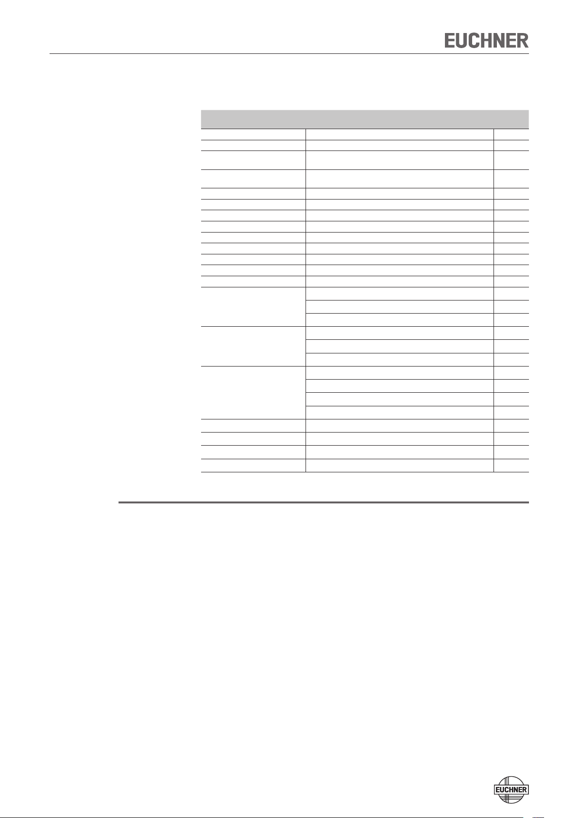
Ordering information and accessories
Designation Version Order
CES-AR-CR2-AH-SG-105751 unicode, door hinge right, plug connector M8, 8-pin 105751
CES-AR-CL2-AH-SG-105753 unicode, door hinge left, plug connector M8, 8-pin 105753
CES-AR-CR2-AH-SA-105746 unicode, door hinge right, connection cable PUR, length 1 m,
CES-AR-CL2-AH-SA-105748 unicode, door hinge left, connection cable PUR, length 1 m,
CES-AR-CR2-AH-L05-109046 unicode, door hinge right, connection cable PUR, length 5 m 109046
CES-AR-CL2-AH-L05-109047 unicode, door hinge left, connection cable PUR, length 5 m 109047
CES-AR-CR2-AH-L10-109050 unicode, door hinge right, connection cable PUR, length 10 m 109050
CES-AR-CL2-AH-L10-109051 unicode, door hinge left, connection cable PUR, length 10 m 109051
CES-AR-CR2-AH-L20-109054 unicode, door hinge right, connection cable PUR, length 20 m 109054
CES-AR-CL2-AH-L20-109055 unicode, door hinge left, connection cable PUR, length 20 m 109055
Bridging plug M12, 4-pin, plug 097645
Y-distributor M12, 1x8-pin, 2x5-pin 097627
Y-distributor with connection cable M12, 1x8-pin, 2x5-pin 111696
Connection cable M12, 8-pin, PVC,
open cable end, conductor crosssection 0.25 mm²
Connection cable M8, 8-pin, PUR,
open cable end, conductor crosssection 0.14 mm²
Connection cable M8, 8-pin, PVC,
open cable end, conductor crosssection 0.14 mm²
Actuator CES-A-BLN-R2 95 mm x 30 mm x 12 mm, door hinge right 100776
Actuator CES-A-BLN-L2 95 mm x 30 mm x 12 mm, door hinge left 104510
Actuator CES-A-BLN-U2 55 mm x 30 mm x 12 mm 103450
Actuator CES-A-BDN-06 26 mm x ∅ 6 mm 104730
with plug connector M12, 8-pin
with plug connector M12, 8-pin
M12, 8-pin, 5 m 100177
M12, 8-pin, 10 m 100178
M12, 8-pin, 20 m 100179
M8, 8-pin, 5 m 106671
M8, 8-pin, 10 m 106672
M8, 8-pin, 20 m 106673
M8, 8-pin, 5 m 110933
M8, 8-pin, 10 m 110934
M8, 8-pin, 15 m 110935
M8, 8-pin, 20 m 111603
No.
105746
105748
Tip!
You will find further connection material, in particular for series connection, in the
current Non-Contact Safety System CES catalog at www.euchner.de.
32
Page 33

Operating Instructions Safety Switches CES-AR-C.2-AH
Inspection and service
Warning!
Loss of the safety function because of damage to the system.
In case of damage, the related component must be replaced completely.
Only accessories or spare parts that can be ordered from EUCHNER may be
replaced.
Regular inspection of the following is necessary to ensure trouble-free long-term
operation:
Ì Check the switching function (see section Functional check)
Ì Check the secure fastening of the devices and the connections
Ì Check for soiling
No servicing is required, repairs to the device are only allowed to be made by the
manufacturer.
Note!
The year of manufacture can be seen in the lower right corner of the rating plate.
The current version number in the format (V X.X.X) can also be found on the device.
Service
The safety door must be re-adjusted when the device indicates that the actuator
is in the boundary area.
If service support is required, please contact:
EUCHNER GmbH + Co. KG
Kohlhammerstraße 16
D-70771 Leinfelden-Echterdingen
Service telephone:
+49 711 7597-500
E-mail:
info@euchner.de
Internet:
www.euchner.de
33
Page 34

Operating Instructions Safety Switches CES-AR-C.2-AH
Declaration of conformity
34
Page 35

Operating Instructions Safety Switches CES-AR-C.2-AH
35
Page 36

More than safety.
Euchner GmbH + Co. KG
Kohlhammerstraße 16
D-70771 Leinfelden-Echterdingen
info@euchner.de
www.euchner.de
Edition:
109309-05-05/13
Title:
Operating Instructions Safety Switches CES-AR-C.2-AH
(translation of the original operating instructions)
Copyright:
© EUCHNER GmbH + Co. KG, 05/2013
Subject to technical modifications,
no responsibility is accepted for the accuracy of this information.
 Loading...