

Page 1

EN
Operating Instructions
Non-Contact Safety System
CES-A-AEA-02B/CES-A-AEA-04B (Unicode)
Page 2

Operating Instructions
Non-Contact Safety System CES-A-AEA-02B/CES-A-AEA-04B
2
(translation of the original operating instructions) 2084606-19-09/17
Contents
1. About this document ............................................................................................. 4
1.1. Scope ............................................................................................................................................4
1.2. Target group ..................................................................................................................................4
1.3. Key to symbols ...............................................................................................................................4
1.4. Supplementary documents ..............................................................................................................4
2. Correct use .......................................................................................................... 5
3. Description of the safety function .......................................................................... 6
4. Exclusion of liability and warranty ......................................................................... 7
5. General safety instructions.................................................................................... 7
6. Function ............................................................................................................... 8
6.1. Block diagrams CES-A-AEA-… ..........................................................................................................9
7. Mounting ............................................................................................................ 11
8. Electrical connection .......................................................................................... 12
8.1. Notes about ..........................................................................................................................12
8.2. Safety in case of faults ..................................................................................................................12
8.3. Fusing of the power supply and the safety contacts .........................................................................12
8.4. Connection example CES-A-AEA-02B ..............................................................................................13
8.5. Connection example CES-A-AEA-04B ..............................................................................................14
9. Setup ................................................................................................................. 15
9.1. LED indicators ..............................................................................................................................15
9.2. Teach-in operation .........................................................................................................................15
9.2.1. Changing the conguration/new actuators ......................................................................16
9.3. Functional check ...........................................................................................................................16
9.3.1. Self-test with test input TST ...........................................................................................16
10. System status table ............................................................................................ 18
11. Technical data .................................................................................................... 19
11.1. Evaluation unit CES-A-AEA-02B .......................................................................................................19
11.2. Evaluation unit CES-A-AEA-04B .......................................................................................................21
11.3. Read head CES-A-LNA-… ...............................................................................................................23
11.4. Read head CES-A-LNA-SC ..............................................................................................................25
11.5. Read head CES-A-LCA-… ...............................................................................................................27
11.6. Read head CES-A-LQA-SC ..............................................................................................................29
11.7. Read head CES-A-LMN-SC ..............................................................................................................31
11.8. Actuator CES-A-BBA/CES-A-BCA .....................................................................................................33
11.9. Actuator CES-A-BQA ......................................................................................................................34
Page 3

3
2084606-19-09/17 (translation of the original operating instructions)
Operating Instructions
Non-Contact Safety System CES-A-AEA-02B/CES-A-AEA-04B
EN
11.10. Actuator CES-A-BDA ......................................................................................................................35
11.11. Actuator CES-A-BMB .....................................................................................................................36
12. Ordering information and accessories ................................................................. 37
13. Inspection and service ........................................................................................ 37
14. Service .............................................................................................................. 37
15. Declaration of conformity ................................................................................... 38
Page 4
Operating Instructions
Non-Contact Safety System CES-A-AEA-02B/CES-A-AEA-04B
4
(translation of the original operating instructions) 2084606-19-09/17
1. About this document
1.1. Scope
This document is valid for
Ì Non-Contact Safety System CES‑A‑AEA‑02B, evaluation unit for two read heads (order no. 092560)
Ì Non-Contact Safety System CES‑A‑AEA‑04B, evaluation unit for four read heads (order no. 072000)
1.2. Target group
Design engineers and installation planners for safety devices on machines, as well as setup and servicing staff possessing
special expertise in handling safety components.
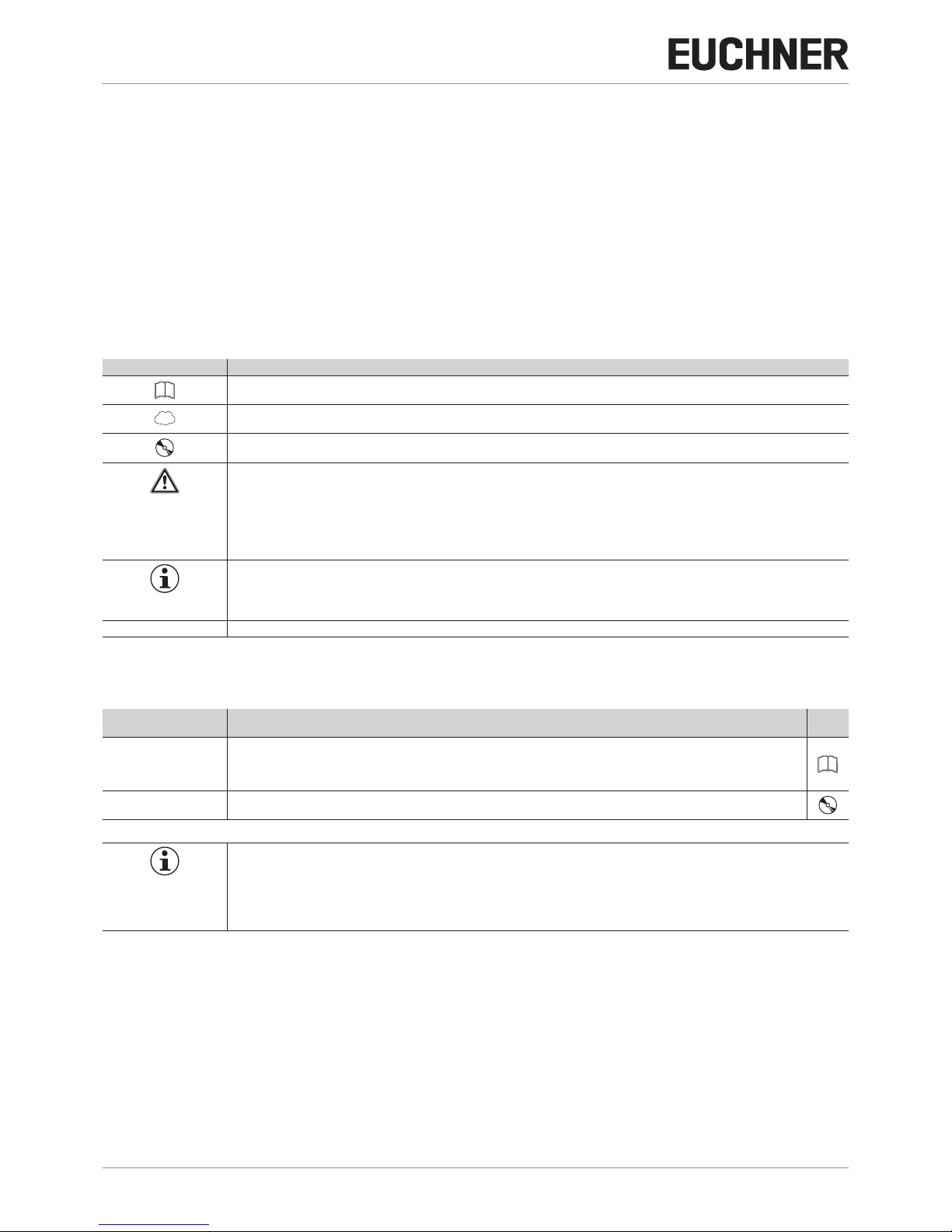
1.3. Key to symbols
Symbol/depiction Meaning
Printed document
www
Document is available for download at www.euchner.com
Document on CD
DANGER
WARNING
CAUTION
Signal
word:
DANGER
WARNING
CAUTION
Consequence if not observed:
Death or severe injuries
Possibly death or severe injuries
Possibly minor injuries
NOTICE
Important!
Signal
word:
NOTICE
Important!
Malfunction or device damage possible
Important information
Tip Useful information
1.4. Supplementary documents
The overall documentation for this device consists of the following documents:
Document title
(document number)
Contents
Safety information and
maintenance CES-A…/
CES-AZ/CES-FD
(2109083)
Ì Basic safety information
Ì Maintenance instructions
Operating Instructions
(2084606)
(This document)
Important!
Always read all documents to gain a complete overview of safe installation, setup and use of the
device. The documents can be downloaded from www.euchner.com. For this purpose enter the doc.
no. in the search box.
Page 5

5
2084606-19-09/17 (translation of the original operating instructions)
Operating Instructions
Non-Contact Safety System CES-A-AEA-02B/CES-A-AEA-04B
EN
2. Correct use
Evaluation units of the series CES-A are used to evaluate safety-related signals from EUCHNER read heads. The system
forms an interlocking device without guard locking. It meets the requirements according to ENIEC60947-5-3.
The system consists of evaluation unit, read head and actuator. It forms an interlocking device with high coding level (type4).
In combination with a movable safety guard and the machine control, this system prevents dangerous machine functions from
occurring while the safety guard is open. A stop command is triggered if the safety guard is opened during the dangerous
machine function.
This means:
Ì Starting commands that cause a dangerous machine function must become active only when the safety guard is closed.
Ì Opening the safety guard triggers a stop command.
Ì Closing a safety guard must not cause automatic starting of a dangerous machine function. A separate start command
must be issued. For exceptions, refer to EN 12100 or relevant C-standards.
Before use, a risk assessment must be performed on the machine, e.g. according to the following standards:
Ì ENISO13849-1, Safety of machinery – Safety-related parts of control systems – Part 1: General principles for design
Ì ENISO12100, Safety of machinery – General principles for design – Risk assessment and risk reduction
Ì IEC62061, Safety of machinery – Functional safety of safety-related electrical, electronic and programmable electronic
control systems.
Correct use includes observing the relevant requirements for installation and operation, e.g. according to the following
standards:
Ì ENISO13849-1, Safety of machinery – Safety-related parts of control systems – Part 1: General principles for design
Ì ENISO14119, Safety of machinery – Interlocking devices associated with guards – Principles for design and selection
Ì EN60204-1, Safety of machinery – Electrical equipment of machines.
The following components can be connected to the evaluation unit CES-A-AEA…:
Ì CES read heads
Ì CEM read heads
Ì CET read heads
For further information, refer to the operating instructions of the corresponding component and to Table 1: Possible com‑
binations for CES components on page 6.
Important!
Ì The user is responsible for the proper integration of the device into a safe overall system. For this
purpose, the overall system must be validated, e.g. in accordance with ENISO13849-2.
Ì Correct use requires observing the permissible operating parameters (see technical data).
Ì If a data sheet is included with the product, the information on the data sheet applies.
Ì It is only allowed to use components that are permissible in accordance with the table below.
Page 6
Operating Instructions
Non-Contact Safety System CES-A-AEA-02B/CES-A-AEA-04B
6
(translation of the original operating instructions) 2084606-19-09/17
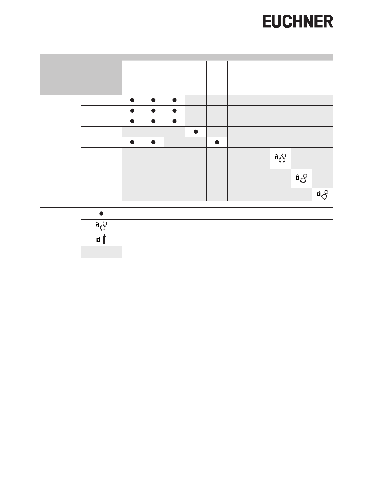
Table 1: Possible combinations for CES components
Evaluation unit Read head
Actuator
CES-A-BBA
071840
CES-A-BCA
088786
CES-A-BDA
084720
CES-A-BMB
077791
CES-A-BQA
098108
CES-A-NBA-...
All items
CES-A-BPA
098775
CEM-A-BE05
094805
CEM-A-BH10
095175
CET-A-BWK-50X
096327
CES-A-AEA-02B
092560
CES-A-AEA-04B
072000
CES-A-LNA...
All items
CES-A-LNA-SC
077715
CES-A-LCA...
All items
CES-A-LMN-SC
077790
CES-A-LQA-SC
095650
CEM-A-LE05K-S2
094800
CEM-A-LE05R-S2
095792
CEM-A-LH10K-S3
095170
CEM-A-LH10R-S3
095793
CET-AX
Key to symbols
Combination possible
Combination possible, guard locking for process protection
Combination possible, guard locking for personal protection
Combination not permissible
3. Description of the safety function
Devices from this series feature the following safety functions:
The following applies in combination with read heads without guard locking (CES read heads) and read heads with guard
locking for process protection (CEM/CET read heads):
Monitoring of the position of a safety guard
(interlocking device according to EN ISO 14119)
Ì Safety function:
- The safety contacts are switched off when the safety guard is open (see chapter 11. Technical data on page 19).
Ì Safety characteristics: category, Performance Level, PFH
D
(see Technical data on Page 20 and Page 22).
Page 7
7
2084606-19-09/17 (translation of the original operating instructions)
Operating Instructions
Non-Contact Safety System CES-A-AEA-02B/CES-A-AEA-04B
EN
4. Exclusion of liability and warranty
In case of failure to comply with the conditions for correct use stated above, or if the safety instructions are not followed,
or if any servicing is not performed as required, liability will be excluded and the warranty void.
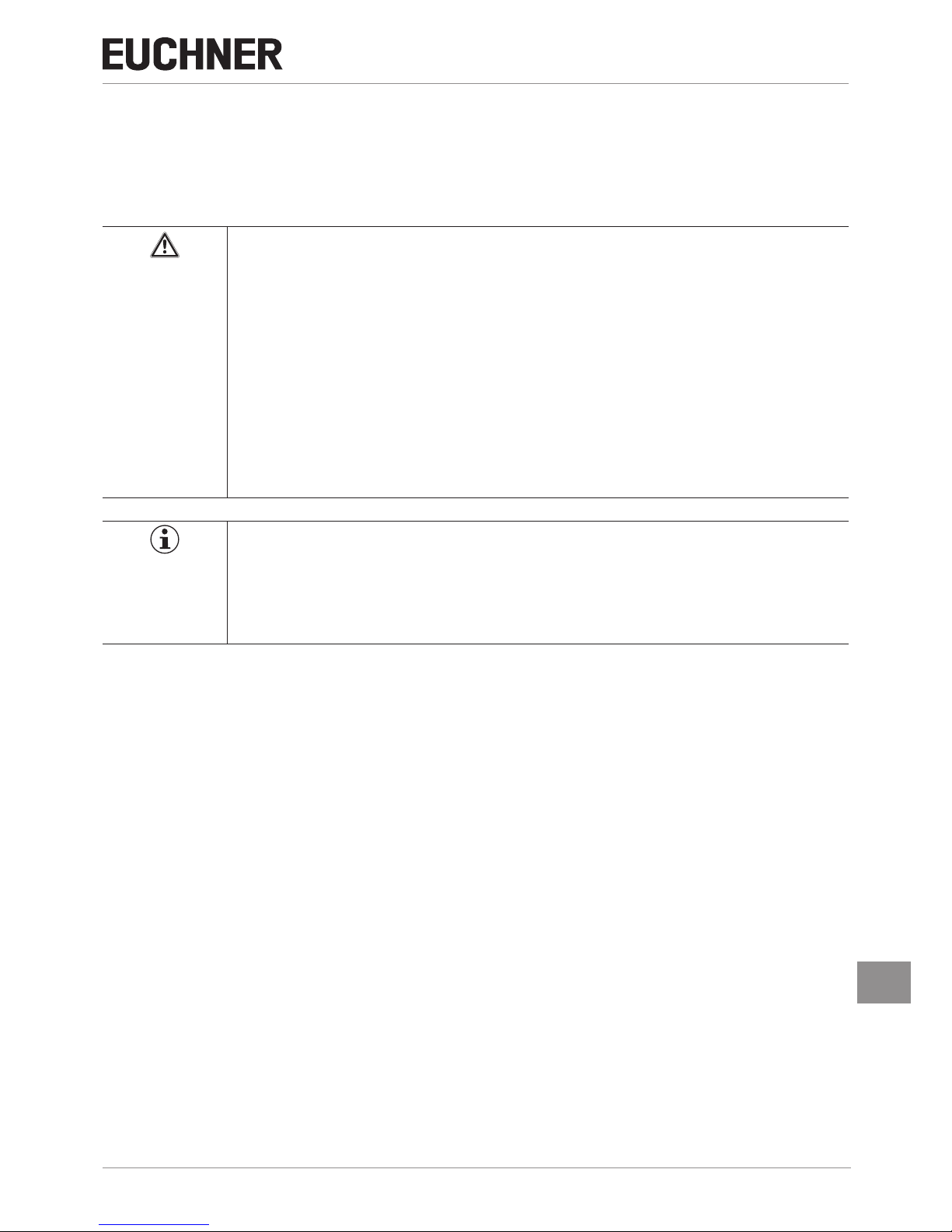
5. General safety instructions
WARNING
Danger to life due to improper installation or due to bypassing (tampering). Safety components fulll
a personal protection function.
Ì Safety components must not be bypassed, turned away, removed or otherwise rendered ineffec-
tive. On this topic pay attention in particular to the measures for reducing the possibility of bypassing according to ENISO14119:2013, section 7.
Ì The switching operation must be triggered only by actuators designated for this purpose.
Ì Mounting, electrical connection and setup only by authorized personnel possessing the following
knowledge:
- specialist knowledge in handling safety components
- knowledge about the applicable EMC regulations
- knowledge about the applicable regulations on occupational safety and accident prevention.
Ì The number of teach-in and switching operations is saved in the internal memory of the evaluation
unit. If necessary, this memory can be read by the manufacturer.
Important!
Prior to use, read the operating instructions and keep these in a safe place. Ensure the operating
instructions are always available during mounting, setup and servicing. EUCHNER cannot provide any
warranty in relation to the readability of the CD for the storage period required. For this reason you
should archive a printed copy of the operating instructions. You can download the operating instructions from www.euchner.com.
Page 8

Operating Instructions
Non-Contact Safety System CES-A-AEA-02B/CES-A-AEA-04B
8
(translation of the original operating instructions) 2084606-19-09/17
6. Function
The safety system consists of three components:
Ì Coded actuator
Ì Read head
Ì Evaluation unit
The number of read heads that can be connected depends on the evaluation unit:
Ì CES-A-AEA-02B: two read heads
Ì CES-A-AEA-04B: four read heads
The evaluation unit can be congured so that a start button (monitoring of the falling edge) and a feedback loop can be
connected to monitor external relays and contactors. The individual conguration is dened by a setup procedure (see
chapter 9. Setup on page 15).
The read heads and actuators are assigned to the device in a special teach-in operation.
Each delivered actuator possesses a unique electronic coding and so is a unique element in the system used. The code in
an actuator cannot be reprogrammed.
The read heads are fastened to the xed part of the safety guard and are each connected to the evaluation unit via a twocore shielded cable (terminals H.1, H.2 and SH.).
The actuator fastened to the movable part of the safety guard is moved towards the read head by closing the door. When the
switch-on distance is reached, power is supplied to the actuator by the read head by induction and data can be transferred.
The read code is compared with the taught-in code in the evaluation unit.
If the data match, door monitoring output O1…O2 or O1…O4 (semiconductor output) on the related read head is set to HIGH.
If all data for all read heads activated match, the safety outputs (relay output) are then enabled. The OUT LED illuminates.
Optionally, a feedback loop can be connected to the evaluation unit. The evaluation unit can then only be started with the
feedback loop closed. A welded contactor contact in the enable path will thus be detected the next time the machine is started.
Due to the combination of dynamic polling of the actuators and the redundant, diverse design of the safety electronics with
redundantly controlled safety outputs, the evaluation unit will enter the safe state with every detectable fault.
When a safety guard is opened or when guard locking is released, the safety outputs switch off the safety circuit and the
OUT LED goes out. The state of the safety outputs is monitored internally by positively driven NC contacts (relay output).
Independent of the switching state of the safety circuit, the position of all safety doors can be polled via the outputs O1…
O2 or O1…O4 .
If an internal fault occurs in the evaluation unit, the safety circuit is switched off, the diagnostic output (DIA) is set to HIGH
and the DIA LED illuminates red.
Page 9
9
2084606-19-09/17 (translation of the original operating instructions)
Operating Instructions
Non-Contact Safety System CES-A-AEA-02B/CES-A-AEA-04B
EN
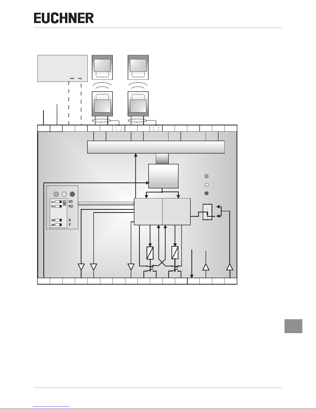
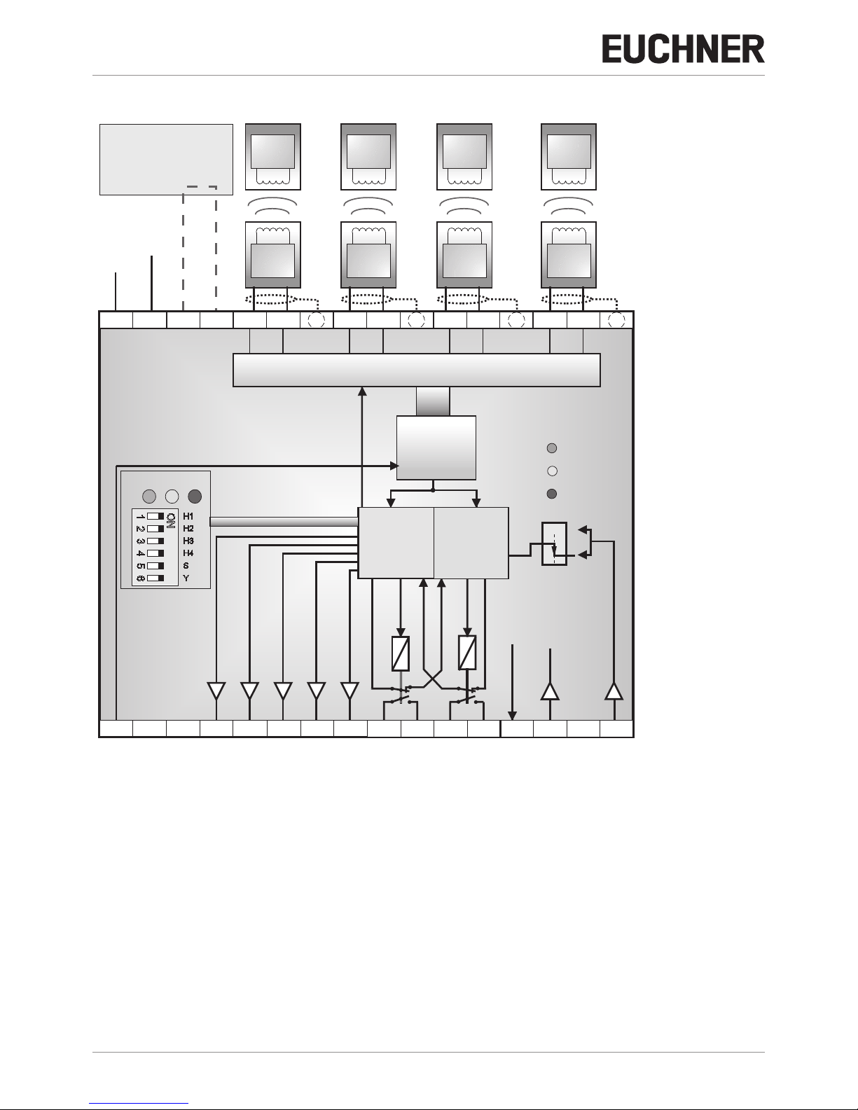
6.1. Block diagrams CES-A-AEA-…
CES-A-AEA-02B
Trans-
ponder
Trans-
ponder
Kopf 1 Kopf 2
A B
0 V
UB
TST
0V
S
H11 H21H12 H22SH1 SH2
DIA
14
1323 Y1
24 Y2
Demodulator
Filter
Verstärker
Komparator
KA
KB
Kopf - HF - Multiplexer
( 1 aus 4 )
J2
J1
O1 O2
+24 V
KA
KB
CPU-A
(Typ 1)
LED
STAT E
OUT
DIA
Star t
CPU-B
(Typ 2)
STATEOUT DIA
Y
S
H2
H1
ON
1 2
5 6
Activation of the
teach-in operation with
jumper
on J1, J2
Read heads
Coded
actuators
Trans-
ponder
Trans-
ponder
Head 1
Head 2
DC
+ 24 V
Operating
voltage
Demodulator
Filter
Amplifier
Comparator
Head selection
CPU-A
(type 1)
Head - RF - multiplexer
(1 of 2)
CPU-B
CPU-B
CPU-A
CPU-A
Start
CPU-B
(type 2)
DIP switch
+UB, 0 V Power supply
J1, J2 Jumper for teach-in operation
H11/H12/H21/H22 Connection for read heads 1 ... 2
SH1, SH2 Shield
TST Test input (see chapter 9.3.1. Self‑test with test input TST on page 16)
O1 ... O2 Semiconductor monitoring outputs
DIA Diagnostic output
13, 14 Connection for relay contact A, safety relay enable
23, 24 Connection for relay contact B, safety relay enable
Y1, Y2 Feedback loop
S Start button connection (monitoring of the falling edge)
Page 10
Operating Instructions
Non-Contact Safety System CES-A-AEA-02B/CES-A-AEA-04B
10
(translation of the original operating instructions) 2084606-19-09/17
CES-A-AEA-04B
Trans-
ponder
Trans-
ponder
Trans-
ponder
Trans-
ponder
Kopf 1 Kopf 2 Kopf opf 4
A
B
C
D
0 V
0V
S
H11
H31
H21
H41
H12
H32
H22
H42
SH1
SH3
SH2
SH4
O3 O4
14
13
23 24
Y2
Demodul ator
Filter
Verstärker
Komparat or
KA
KB
K
( 1 aus 4
TST
0V
J2
J1
O1 O2 DIA 23
Y1
24 Y2
+24 V
KA
KB
CPU-A
(Typ 1)
LED
STATE
OUT
DIA
Star tStart
CPU-B
(Typ 2)
STATEOUT DIA
UB
Y
S
H4
H3
H2
H1
ON
1 2
3
4
5 6
Head selection
Demodulator
Filter
Amplifier
Comparator
CPU-A
(type 1)
Head -RF - mulitplexer
(1 of 4)
CPU-B
CPU-B
CPU-A
CPU-A
CPU-B
(type 2)
DIP switch
Activation of the
teach-in operation with
jumper
on J1, J2
Read heads
Coded
actuators
Trans-
ponder
Head 1
DC
+ 24 V
Operating
voltage
Trans-
ponder
Trans-
ponder
Trans-
ponder
Head 2
Head 3 Head 4
+UB, 0 V Power supply
J1, J2 Jumper for teach-in operation
H11/H12...H41/H42 Connection for read heads 1 ... 4
SH1 ...SH4 Shield
TST Test input (see chapter 9.3.1. Self‑test with test input TST on page 16)
O1 ... O4 Semiconductor monitoring outputs
DIA Diagnostic output
13, 14 Connection for relay contact A, safety relay enable
23, 24 Connection for relay contact B, safety relay enable
Y1, Y2 Feedback loop
S Start button connection (monitoring of the falling edge)
Page 11

11
2084606-19-09/17 (translation of the original operating instructions)
Operating Instructions
Non-Contact Safety System CES-A-AEA-02B/CES-A-AEA-04B
EN
7. Mounting
NOTICE
Device damage due to improper installation or unsuitable ambient conditions.
Ì Read heads and actuators must not be used as a mechanical end stop.
Ì Observe EN ISO 14119:2013, sections 5.2 and 5.3, for information about fastening the safety
switch and the actuator.
Ì Observe EN ISO 14119:2013, section 7, for information about reducing the possibilities for by-
passing an interlocking device.
Ì The evaluation unit must be mounted in a control cabinet with a minimum degree of protection of
IP54. A snap-in element on the rear of the device is used for fastening to a mounting rail.
Ì If several evaluation units are mounted side by side in a control cabinet without air circulation (e.g.
fan), a minimum distance of 10mm must be maintained between the evaluation units. This distance enables the heat from the evaluation unit to dissipate.
Important!
Ì From the assured switch-off distance S
ar
, the safety outputs are safely shut down.
Ì When mounting several read heads, observe the stipulated minimum distance to avoid mutual in-
terference.
- For CES-A-LNA/-LCA s
min
=50mm
- For CES-A-LMN s
min
=20mm
- For CES-A-LQA s
min
=80mm
s
min
Ì If the actuator is installed ush, the switching distance changes as a function of the installation
depth and the safety guard material.
Operating
distance
Actuator
Operating
distance
Actuator
Flush mounting Surface mounting
Note the following points:
Ì Actuator and read head must be tted so that
- the front faces are at the minimum switch-on distance 0.8xSao or closer when the safety guard is closed (see section
Operating distances). To avoid entering the area of possible side lobes, a minimum distance is to be maintained in
case of a side approach direction. See section Typical operating distance for the related actuator.
- a hazard is excluded until the assured switch-off distance (Sar) is reached when the safety guard is open.
- the actuator is positively mounted on the safety guard, e.g. by using the safety screws included.
- they cannot be removed or tampered with using simple means.
Ì Pay attention to the maximum tightening torque for the read head or safety switch and actuator mountings of 1Nm. For
read heads/actuators made of PE-HD, the maximum tightening torque is only 0.5Nm.
Page 12
Operating Instructions
Non-Contact Safety System CES-A-AEA-02B/CES-A-AEA-04B
12
(translation of the original operating instructions) 2084606-19-09/17
8. Electrical connection
WARNING
In case of an error, loss of the safety function through incorrect connection.
Ì Monitoring outputs must not be used as safety outputs.
Ì Lay the connection cables with protection to prevent the risk of short circuits.
NOTICE
Risk of damage to equipment or malfunctions as a result of incorrect connection.
Ì All the electrical connections must either be isolated from the mains supply by a safety transform-
er according to IEC 61558-2-6 with limited output voltage in the event of a fault, or by other equivalent isolation measures.
Ì All electrical outputs must have an adequate protective circuit for inductive loads. The outputs
must be protected with a free-wheeling diode for this purpose. The switch-on current may have to
be limited for capacitive loads.
Ì The tightening torque for the screws on the connection terminals must be 0.6…0.8Nm.
Ì The connection cable for the read heads must only be extended using EUCHNER plug connectors,
and adequate consideration must be given to EMC. Intermediate terminals must not be used.
Ì The shield on the connection cable for the read head must be connected to the appropriate termi-
nal SH1…4 on the evaluation unit. The portion of cable from which insulation is stripped should
be kept as short as possible (max. 3cm).
8.1. Notes about
Important!
Ì For use and operation as per the requirements
1)
, a power supply with the feature “for use in
class 2 circuits” must be used.
Alternative solutions must comply with the following requirements:
a) Electrically isolated power supply unit with a max. open-circuit voltage of 30V/DC and a limited
current of max. 8A.
b) Electrically isolated power supply unit in combination with fuse as per UL248. This fuse should be
designed for max. 3.3A and should be integrated into the 30VDC voltage section.
Ì Use cable material made of copper wire with a temperature resistance of at least 75°C.
1) Note on the scope of the UL approval: the devices have been tested as per the requirements of UL508 and CSA/ C22.2 no. 14 (protection against electric shock
and re).
8.2. Safety in case of faults
Ì The operating voltage U
B
is reverse polarity protected.
Ì The connections for the read heads are not short circuit-proof.
Ì A short circuit between 13/14 and 23/24 can be detected only by means of external pulsing.
Ì A short circuit in the cable can be excluded by laying the cable with protection.
8.3. Fusing of the power supply and the safety contacts
Ì Provide external contact fuses (6AgG fuse or 6A circuit breaker, characteristic B or C) for relay outputs.
Ì The power supply must be protected with a max. 8A fuse ahead of terminal U
B
.
Page 13
13
2084606-19-09/17 (translation of the original operating instructions)
Operating Instructions
Non-Contact Safety System CES-A-AEA-02B/CES-A-AEA-04B
EN
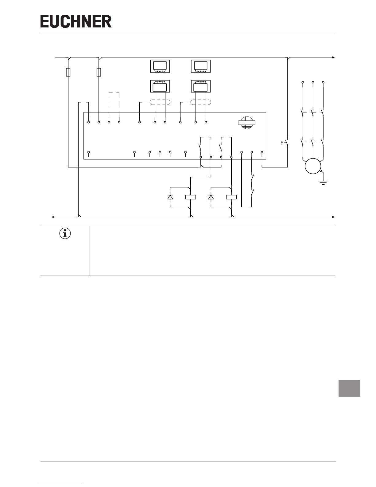
8.4. Connection example CES-A-AEA-02B
24 VDC
GND
-F1
0V
TST
-F2
UB
CES-A-AEA-02B
092560
J1 J2
O1
SH1
O2
Readhead
1
H11
Transponder
O3
H12
O4
-V1
SH2
DIA
-K1
A1
A2
Readhead
2
H21
Transponder
23
H22
24
-V2
13 14
-K2
A1
A2
feedback loop
Y1
EUCHNER
Y2
-K2
21
22
-K1
21
22
S
Start
L1
-K1
13
14
-K2
13
14
M
3
~
-M1
L2
23
24
23
24
L3
33
34
33
34
Important!
To achieve category 4 according to EN ISO 13849-1, it is necessary to monitor the downstream
contactors (here: contacts of -K3 and -K4 in the feedback loop).
This example shows only an excerpt that is relevant for connection of the CES system. The example
illustrated here does not show complete system planning. The user is responsible for safe integration
into the overall system.
Page 14

Operating Instructions
Non-Contact Safety System CES-A-AEA-02B/CES-A-AEA-04B
14
(translation of the original operating instructions) 2084606-19-09/17
8.5. Connection example CES-A-AEA-04B
24 VDC
GND
-F1
0V
TST
-F2
UB
CES-A-AEA-04B
072000
J1 J2
SH1
O1
Readhead
1
H11
Transponder
O2
H12
EUCHN ER
O3
SH2
O4
-V1
Readhead
2
H21
DIA
Transponder
H22
-K1
A1
A2
23
SH3
24
-V2
Read-
head
3
H31
Transponder
13
H32
14
-K2
A1
A2
feedback loop
SH4
Y1
Readhead
4
H41
Y2
-K2
21
22
-K1
21
22
Transponder
H42
S
Start
L1
-K1
13
14
-K2
13
14
M
3
~
-M1
L2
23
24
23
24
L3
33
34
33
34
Important!
To achieve category 4 according to EN ISO 13849-1, it is necessary to monitor the downstream
contactors (here: contacts of -K3 and -K4 in the feedback loop).
This example shows only an excerpt that is relevant for connection of the CES system. The example
illustrated here does not show complete system planning. The user is responsible for safe integration
into the overall system.
Page 15

15
2084606-19-09/17 (translation of the original operating instructions)
Operating Instructions
Non-Contact Safety System CES-A-AEA-02B/CES-A-AEA-04B
EN
9. Setup
9.1. LED indicators
Designation Color Meaning
STATE green Status indication (multifunction display using ashing modes)
OUT yellow Safety circuit closed
DIA red
Ì Operating fault or
Ì External fault (fault in the feedback loop) or
Ì Teach-in operation not valid or
Ì Internal device fault or
Ì TST input activated (function test active)
9.2. Teach-in operation
Before the system forms a functional unit, the parameters are set in the evaluation unit using a teach-in operation (number
of connected read heads, assignment of the actuators to the read heads, with or without automatic start, with or without
feedback loop). During this process the read heads are activated and the actuator code taught-in.
These conguration parameters are saved in the device.
During the teach-in operation the safety outputs are open. The system is in the safe state.
Important!
Ì The teach-in operation can differ for read heads that are not described in this document. Observe
the information in the operating instructions for the read head used.
Ì During the teach-in operation the following conditions must be met:
- There must be no state change, e.g. opening or closing of a safety door or a change in the signal on the terminals for the start button and the feedback loop.
- The power supply must not be switched off.
Ì If these conditions are not met, the evaluation unit switches to the safe fault state (diagnostics LED
illuminates) and signals this operating fault with the STATE LED by three short ashes that are repeated every second. The teach-in operation must be repeated.
Ì The number of teach-in operations is unlimited. The evaluation unit can be re-congured as often
as required.
Ì Actuators cannot be interchanged without a renewed teach-in operation.
Ì An actuator that has not been subjected to teach-in will not be detected by the related read head.
Ì Even if only one new actuator needs to be taught, a complete new teach-in operation must be car-
ried out.
Ì Do not change DIP switches during operation.
To trigger a teach-in operation, the user must perform the following actions in the stipulated order:
1. Prepare for teach-in operation
- Switch off power supply U
B
- Fit a jumper between terminals J1 and J2
2. Set required conguration on DIP switches
Switch designation Switch position left (OFF) Switch position right (ON)
1 No read head connected to terminals H11, H12, SH1 Read head connected to terminals H11, H12, SH1
2 No read head connected to terminals H21, H22, SH2 Read head connected to terminals H21, H22, SH2
3 No read head connected to terminals H31, H32, SH3 Read head connected to terminals H31, H32, SH3
4 No read head connected to terminals H41, H42, SH4 Read head connected to terminals H41, H42, SH4
5 Automatic start
(no start button connected)
Manual start
(start button connected)
6 No feedback loop connected Feedback loop connected
3. Set required conguration on machine
- Close all doors to be monitored (the actuators must be in the operating distance of the related read head)
- For Manual start operating mode: keep start button closed
- For With feedback operating mode: keep feedback loop closed
Page 16

Operating Instructions
Non-Contact Safety System CES-A-AEA-02B/CES-A-AEA-04B
16
(translation of the original operating instructions) 2084606-19-09/17
4. Start teach-in operation
- Switch on operating voltage
- Wait for self-test (STATE LED ashes for approx. 10 seconds at 15Hz)
- Teach-in operation starts (STATE LED ashes at approx. 1Hz)
- Wait for acknowledgment of the teach-in operation (STATE LED goes out after approx. 10 seconds)
5. End teach-in operation
- Remove jumper between J1 and J2
- For Manual start operating mode: start button must be connected
- For With feedback operating mode: feedback loop must be connected
- Interrupt operating voltage for at least 10 seconds
- Wait for self-test (STATE LED ashes for approx. 10 seconds at 15Hz)
6. Check all safety guards for effectiveness
9.2.1. Changing the conguration/new actuators
The evaluation unit can be re-congured as often as required. For this purpose you must proceed as per the rst teach-in
operation according to the section 9.2. Teach‑in operation on page 15. Faulty actuators can be replaced. Then again a
complete teach-in operation must be performed.
9.3. Functional check
After installation and any fault, the safety function must be fully checked. Proceed as follows:
WARNING
Danger of fatal injury as a result of faults in installation and functional check.
Ì Before carrying out the functional check, make sure that there are no persons in the danger area.
Ì Observe the valid accident prevention regulations.
1. Switch on operating voltage.
- The safety switch carries out a self-test.
The green STATE LED ashes for approx. 10 seconds at 15Hz.
The STATE LED then illuminates continuously.
The OUT and DIA LEDs do not illuminate.
2. Close all safety guards.
- The machine must not start automatically.
- The green STATE LED and the yellow OUT LED light up continuously.
3. Enable operation in the control system.
4. Open the safety guard.
- The machine must switch off and it must not be possible to start it as long as the safety guard is open.
- The green STATE LED illuminates continuously; the OUT and DIA LEDs do not illuminate.
Repeat steps 2…4 separately for each safety guard.
9.3.1. Self-test with test input TST
On electromechanical safety switches or magnetic switches, the function test can be performed by cyclically opening the
safety guard.
From category 2 according to ENISO13849-1 and in accordance with EN 60204-1 : 1997 (chapter 9.4.2.4), a function
test must be performed on the entire safety system on start-up or after dened intervals.
Testing of the internal function of the unit is not necessary because the device monitors itself in real time. Welding of an
output contact (relay output) is detected by the device at the latest the next time the safety guard is opened. A short circuit
in the output cable is not detected by the device.
In addition, the entire safety circuit can be tested without opening the safety guard. For this purpose, opening of the safety
guard can be simulated by applying 24 V DC to the test input TST.
Page 17

17
2084606-19-09/17 (translation of the original operating instructions)
Operating Instructions
Non-Contact Safety System CES-A-AEA-02B/CES-A-AEA-04B
EN
The safety outputs are switched off, enabling testing of the complete safety circuit. The diagnostic output DIA of the evaluation unit is also set to HIGH as a monitoring function.
When test input TST is reset, the evaluation unit resets the diagnostic output DIA to LOW, the red LED switches off and
normal operation is continued.
In Manual start operating mode, the start button must be pressed again to start the system.
Important!
After the self-test, the test input TST must be connected to 0 V again or must be disconnected.
Page 18

Operating Instructions
Non-Contact Safety System CES-A-AEA-02B/CES-A-AEA-04B
18
(translation of the original operating instructions) 2084606-19-09/17
10. System status table
Operating mode
LED indicator
State
STATE (green)
OUT (yellow)
DIA (red)
Setup
4Hz Initial setup after delivery without jumper connected to J1, J2.
1Hz Teach-in operation
Acknowledgment of completion of teach-in operation.
Normal operation
15Hz
(10 s)
Self-test, duration approx. 10 seconds, is performed after the application of the operating voltage U
B
Normal operation, not all monitored doors are closed.
Normal operation, all monitored doors are closed (after pressing the start button, for Manual start operating
mode)
Function test Function test active (TST input=24 V)
Fault display
Internal component failure or actuator CES-A-BMB in the impermissible range or excessively high external interference (EMC)
Operating fault
3x
Conguration error:
Teach-in operation must be performed again
Possible causes:
- State change during the teach-in operation
- The DIP switch setting and the conguration did not match during the teach-in operation
- DIP switch setting has been changed without teach-in operation
- The jumper (J1, J2) was tted with power supply switched on
- Closed feedback loop (Y1,Y2) present, although a feedback loop was not present during teach-in
- 24 V signal present at the start button input (S) although teach-in was performed with “Automatic start” operating
mode.
4 x
Fault in feedback loop
Possible causes:
- Malfunction of the monitored contactor
- Following removal from the operating distance, actuator is not outside the operating distance long enough; as a
result the feedback loop cannot be closed in this short time. Note the release time for the monitored contactor.
- Feedback loop was not closed on starting the evaluation unit
- Feedback loop was not closed on applying the operating voltage +UB.
Key to symbols
N 0 Volt or not connected
1 24 Volt
0 0 Volt
LED not illuminated
LED illuminated
15Hz (10 s)
LED ashes for 10 seconds at 15Hz
3 x +
LED ashes three times and then illuminates continuously
3 x
LED ashes three times, and this is then repeated
X Any state
Important!
If you do not nd the displayed device status in the System status table, this indicates an internal
device fault. In this case, you should contact the manufacturer.
Page 19

19
2084606-19-09/17 (translation of the original operating instructions)
Operating Instructions
Non-Contact Safety System CES-A-AEA-02B/CES-A-AEA-04B
EN
11. Technical data
11.1. Evaluation unit CES-A-AEA-02B
Ì Housing for rail mounting, IP20
Ì Relay output
Ì Two read heads can be connected
Dimension drawing
45
9
9
1
1
4
Suitable for 35mm mounting rail according to EN60715
Switching characteristics
Ì Two safety outputs
(relay outputs)
Ì Two door monitoring outputs
(semiconductor outputs, not
safety outputs)
Approvals
13
14
23
24
24 VO1
13
14
23
24
24
VO
1
24 VO2 24
VO
2
Safety guard
closed
(all actuators detected)
open
(e.g. actuator 1 not in the operating
distance)
Read head 1 Actuator 1 Read head 1
Page 20

Operating Instructions
Non-Contact Safety System CES-A-AEA-02B/CES-A-AEA-04B
20
(translation of the original operating instructions) 2084606-19-09/17
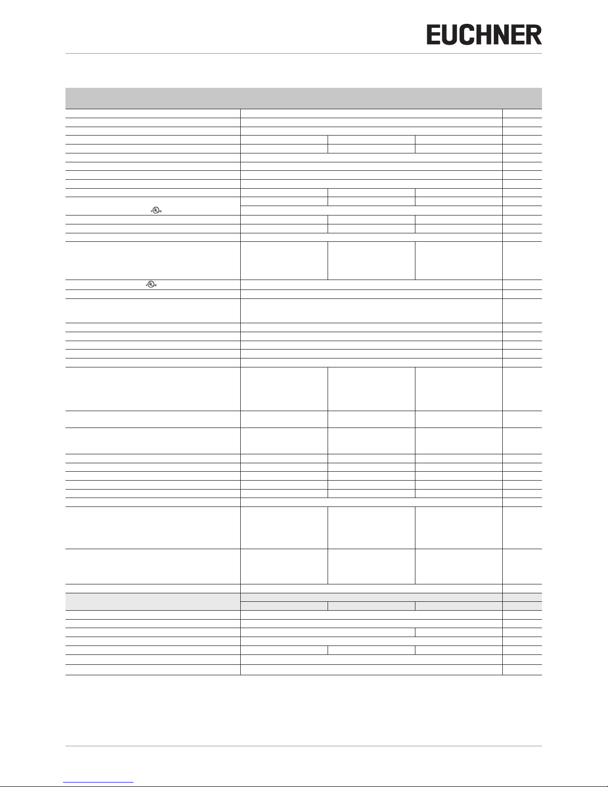
Technical data of CES-A-AEA-02B
Parameter
Value
Unit
min. typ. max.
Housing material PA6.6 plastic
Dimensions 114x99x45 mm
Weight 0.25 kg
Ambient temperature at UB=DC 24 V -20 - +55 °C
Atmospheric humidity, not condensing - - 80 %
Degree of protection IP20
Degree of contamination 2
Mounting Mounting rail 35mm according to DIN EN 60715
Number of read heads Max. two read heads per evaluation unit
Connection (plug-in screw terminals/coded) 0.25 - 2.5 mm²
Operating voltage UB (regulated, residual ripple < 5%) 21 24 27 V DC
For the approval according to the following applies
Operation only with UL class 2 power supply or equivalent measures
Current consumption IB (with relay energized)
1)
- 220 270 mA
External fuse (operating voltage UB) 0.4 - 8 A
Safety contacts 2 (relays with internally monitored contacts)
Switching current (relay outputs)
mA
- at switching voltage AC/DC 1…60 V
1
2)
- 300
- at switching voltage AC/DC 17…30 V 15 - 6,000
- at switching voltage AC 17…230 V 15 - 1,500
Switching load according to
Max. AC 30 V, class 2/max. DC 60 V, class 2
External fuse (safety circuit) according to EN60269-1 6 AgG or 6 A circuit breaker (characteristic B or C)
Utilization category according to EN60947-5-1 AC-12 60 V 0.3 A/DC-12 60 V 0.3 A
AC-12 30 V 6 A/DC-12 30 V 6 A
AC-15 230 V 2 A / DC-13 24 V 3 A
Rated insulation voltage U
i
250 V
Rated impulse withstand voltage U
imp
4 kV
Rated conditional short-circuit current 100 A
Resilience to vibration Acc. to EN60947-5-2
Mechanical operating cycles (relays) 10x10
6
Switching delay from state change
3)
- Two activated actuators - - 290
ms
- One activated actuator - - 210
Discrepancy time of the operating points of both relays
(with two activated actuators)
- - 240 ms
Manual start operating mode
- Start button actuating duration 250 - -
ms
- Start button response delay - 200 300
Current via feedback loop Y1/Y2 5 8 10 mA
Permissible resistance via feedback loop - - 600
W
Ready delay
4)
- 10 12 s
Dwell time
5)
3 - - s
Switching frequency, max
6)
- - 0.25 Hz
Repeat accuracy R acc. to ENIEC60947-5-3 ≤ 10 %
Monitoring outputs (diagnostics DIA, monitoring outputs
01…02, semiconductor output, p-switching, short circuit-protected)
- Output voltage 0.8xU
B
- U
B
V DC
- Max. load - - 20 mA
Start button input S, test input TST
- Input voltage LOW 0 - 2
V DC
HIGH 15 - U
B
- Input current HIGH 5 8 10 mA
EMC protection requirements Acc. to EN60947-5-3
Reliability values acc. to ENISO13849-1
as a function of the switching current at 24 V DC ≤ 0.1 A ≤ 1 A ≤ 3 A
Category 4
Performance Level (PL) e
PFH
D
1.3x10
-8
1.5x10
-8
Mission time 20 years
Number of switching cycles/year 506 000 100 000 23 000
Diagnostic coverage DC 99 %
MTTF
D
136 years
1) Without taking into account the load currents on the monitoring outputs.
2) If a switching current > 300 mA in conjunction with a switching voltage > 15 V or an inductive or capacitive load is switched once using the relay outputs, it is no longer possible to reliably switch small currents
(< 15 mA) due to the contact erosion on the gold contacts.
3) Corresponds to the risk time according to EN60947-5-3. This is the maximum switch-off delay for the safety outputs following removal of the actuator. In case of EMC interference in excess of the requirements
in accordance with EN60947-5-3, the switch-off delay can increase to max. 430 ms. After a brief actuation < 0.4 s, the switch-on delay can increase to max. 3 s if this is followed immediately by further actuation.
4) After the operating voltage is switched on, the relay outputs are switched off and the monitoring outputs are set to LOW potential during the ready delay. For the visual indication of the delay, the green STATE
LED ashes at a frequency of approx. 15Hz.
5) The dwell time is the time that the actuator must be inside or outside the operating distance.
6) In case of monitoring with feedback loop, the actuators must remain outside the operating distance, e.g. with a door open, until the feedback loop is closed.
Page 21

21
2084606-19-09/17 (translation of the original operating instructions)
Operating Instructions
Non-Contact Safety System CES-A-AEA-02B/CES-A-AEA-04B
EN
11.2. Evaluation unit CES-A-AEA-04B
Ì Housing for rail mounting, IP20
Ì Relay output
Ì Four read heads can be connected
Dimension drawing
45
99
114
Suitable for 35mm mounting rail according to EN60715
Switching characteristics
Ì Two safety outputs
(relay outputs)
Ì Four door monitoring outputs
(semiconductor outputs, not
safety outputs)
Approvals
Safety guard
closed
(all actuators detected)
open
(e.g. actuator 1 not in the operating
distance)
Read head 1 Actuator 1 Read head 1
13
14
23
24
24 VO1
13
14
23
24
24
VO
1
24 VO2 24
VO
2
24 VO3 24
VO
3
24 VO4 24
VO
4
Page 22
Operating Instructions
Non-Contact Safety System CES-A-AEA-02B/CES-A-AEA-04B
22
(translation of the original operating instructions) 2084606-19-09/17
Technical data of CES-A-AEA-04B
Parameter
Value
Unit
min. typ. max.
Housing material PA6.6 plastic
Dimensions 114x99x45 mm
Weight 0.25 kg
Ambient temperature at UB=DC 24 V -20 - +55 °C
Atmospheric humidity, not condensing - - 80 %
Degree of protection IP20
Degree of contamination 2
Mounting Mounting rail 35mm according to DIN EN 60715
Number of read heads Max. four read heads per evaluation unit
Connection (plug-in screw terminals/coded) 0.25 - 2.5 mm²
Operating voltage UB (regulated, residual ripple < 5%) 21 24 27 V DC
For the approval according to the following applies
Operation only with UL class 2 power supply or equivalent measures
Current consumption IB (with relay energized)
1)
- 220 270 mA
External fuse (operating voltage UB) 0.4 - 8 A
Safety contacts 2 (relays with internally monitored contacts)
Switching current (relay outputs)
mA
- at switching voltage AC/DC 1…60 V
1
2)
- 300
- at switching voltage AC/DC 17…30 V 15 - 6,000
- at switching voltage AC 17…230 V 15 - 1,500
Switching load according to
Max. AC 30 V, class 2/max. DC 60 V, class 2
External fuse (safety circuit) according to EN60269-1 6 AgG or 6 A circuit breaker (characteristic B or C)
Utilization category according to EN60947-5-1 AC-12 60 V 0.3 A/DC-12 60 V 0.3 A
AC-12 30 V 6 A / DC-12 30 V 6 A
AC-15 230 V 2 A / DC-13 24 V 3 A
Rated insulation voltage U
i
250 V
Rated impulse withstand voltage U
imp
4 kV
Rated conditional short-circuit current 100 A
Resilience to vibration Acc. to EN60947-5-2
Mechanical operating cycles (relays) 10x10
6
Switching delay from state change
3)
- Four activated actuators - - 450
ms
- Three activated actuators - - 370
- Two activated actuators - - 290
- One activated actuator - - 210
Discrepancy time of the operating points of both relays
(with four activated actuators)
- - 400 ms
Manual start operating mode
- Start button actuating duration 250 - -
ms
- Start button response delay - 200 300
Current via feedback loop Y1/Y2 5 8 10 mA
Permissible resistance via feedback loop - - 600
W
Ready delay
4)
- 10 12 s
Dwell time
5)
3 - - s
Switching frequency, max
6)
- - 0.25 Hz
Repeat accuracy R acc. to ENIEC60947-5-3 ≤ 10 %
Monitoring outputs (diagnostics DIA, monitoring outputs
01…04, semiconductor output, p-switching, short circuit-protected)
- Output voltage 0.8xU
B
- U
B
V DC
- Max. load - - 20 mA
Start button input S, test input TST
- Input voltage LOW 0 - 2
V DC
HIGH 15 - U
B
- Input current HIGH 5 8 10 mA
EMC protection requirements Acc. to EN60947-5-3
Reliability values acc. to ENISO13849-1
as a function of the switching current at 24 V DC ≤ 0.1 A ≤ 1 A ≤ 3 A
Category 4
Performance Level (PL) e
PFH
D
1.3x10
-8
1.5x10
-8
Mission time 20 years
Number of switching cycles/year 506 000 100 000 23 000
Diagnostic coverage DC 99 %
MTTF
D
136 years
1) Without taking into account the load currents on the monitoring outputs.
2) If a switching current > 300 mA in conjunction with a switching voltage > 15 V or an inductive or capacitive load is switched once using the relay outputs, it is no longer possible to reliably switch small currents
(< 15 mA) due to the contact erosion on the gold contacts.
3) Corresponds to the risk time according to EN60947-5-3. This is the maximum switch-off delay for the safety outputs following removal of the actuator. In case of EMC interference in excess of the requirements
in accordance with EN60947-5-3, the switch-off delay can increase to max. 750 ms. After a brief actuation < 0.8 s, the switch-on delay can increase to max. 3 s if this is followed immediately by further actuation.
4) After the operating voltage is switched on, the relay outputs are switched off and the monitoring outputs are set to LOW potential during the ready delay. For the visual indication of the delay, the green STATE
LED ashes at a frequency of approx. 15Hz.
5) The dwell time is the time that the actuator must be inside or outside the operating distance.
6) In case of monitoring with feedback loop, the actuators must remain outside the operating distance, e.g. with a door open, until the feedback loop is closed.
Page 23

23
2084606-19-09/17 (translation of the original operating instructions)
Operating Instructions
Non-Contact Safety System CES-A-AEA-02B/CES-A-AEA-04B
EN
11.3. Read head CES-A-LNA-…
Ì Cube-shaped design 42x25mm
Ì Hard-wired cable
Dimension drawing
CES-A-L XXXXXX
25
∅8
∅4,5
42
32
±0,1
12
4,6
"l"
Two M4x14 safety screws
included Active face Active face
Typical operating distance
With evaluation unit CES-A-AEA-… and actuator CES-A-BBA
NOTICE
For a side approach direction for the actuator and read head, a minimum distance of s=3mm must
be maintained so that the operating distance of the side lobes is not entered.
Terminal assignment
Read head with connection cable
H11
H12SH1
BN
WH
Shield
Read head
Evaluation unit
CES-A-AEA-…
Approvals
X
20
15
10
5
20
15
10
5
5
10
15
20
Y
Z
Page 24

Operating Instructions
Non-Contact Safety System CES-A-AEA-02B/CES-A-AEA-04B
24
(translation of the original operating instructions) 2084606-19-09/17
Technical data
Parameter Value Unit
min. typ. max.
Housing material Fortron, reinforced thermoplastic, fully encapsulated
Dimensions 42x25x12 mm
Weight (incl. 10 m cable) 0.3 kg
Ambient temperature -25 - +70 °C
Degree of protection IP67/IP69K
Installation position Any
Method of operation Inductive
Power supply Via evaluation unit
In combination with actuator CES-A-BBA on evaluation unit CES-A-AEA-…
Assured switch-off distance S
ar
- - 32
mm
Operating distance for center offset m=0
1)
- Switch-on distance - 15 -
- Assured switch-on distance S
ao
10 - -
- Switching hysteresis 0.5 2 Minimum distance s for side approach direction - 3 -
In combination with actuator CES-A-BDA on evaluation unit CES-A-AEA-…
Assured switch-off distance S
ar
- - 33
mm
Operating distance for center offset m=0
2)
- Switch-on distance - 16 -
- Assured switch-on distance S
ao
11 - -
- Switching hysteresis 0.5 2 Minimum distance s for side approach direction - 4 Connection cable Hard-wired encapsulated connection cable, with crimped ferrules
PVC, ∅ 4.6mm
PUR, ∅ 4.8mm, suitable for drag chain
Cable length - - 25 m
1) These values apply to surface installation of the read head and the actuator.
2) These values apply to non-metallic surrounding material. Other materials on request.
Page 25

25
2084606-19-09/17 (translation of the original operating instructions)
Operating Instructions
Non-Contact Safety System CES-A-AEA-02B/CES-A-AEA-04B
EN
11.4. Read head CES-A-LNA-SC
Ì Cube-shaped design 42x25mm
Ì M8 plug connector (snap-action and screw terminals)
Dimension drawing
5,5
∅10
6,8
∅8
∅
4,5
4,6
12
25
min.38
32
±0,1
4232,6
A0
CES-A-L 077715
3
4
1
A0
CES-A-L 077715
20 1,
26,5
Two M4x14 safety screws
included
Cable outlet with angled
connector
Active face
Active face
Typical operating distance
With evaluation unit CES-A-AEA-… and actuator CES-A-BBA
NOTICE
For a side approach direction for the actuator and read head, a minimum distance of s=3mm must
be maintained so that the operating distance of the side lobes is not entered.
Approvals
X
20
15
10
5
20
15
10
5
5
10
15
20
Y
Z
Page 26

Operating Instructions
Non-Contact Safety System CES-A-AEA-02B/CES-A-AEA-04B
26
(translation of the original operating instructions) 2084606-19-09/17
Terminal assignment
Read head with plug connector
H11H12 SH1
1
3
4
BN
WH
Shield
View on the plug
connector of the
read head
Evaluation unit
CES-A-AEA-…
Technical data
Parameter Value Unit
min. typ. max.
Housing material Fortron, reinforced thermoplastic, fully encapsulated
Dimensions 42x25x12 mm
Weight (incl. 10 m cable) 0.3 kg
Ambient temperature -25 - +70 °C
Degree of protection IP67/IP69K
Installation position Any
Method of operation Inductive
Power supply Via evaluation unit
In combination with actuator CES-A-BBA on evaluation unit CES-A-AEA-…
Assured switch-off distance S
ar
- - 32
mm
Operating distance for center offset m=0
1)
- Switch-on distance - 15 -
- Assured switch-on distance S
ao
10 - -
- Switching hysteresis 0.5 2 Minimum distance s for side approach direction - 3 -
In combination with actuator CES-A-BDA on evaluation unit CES-A-AEA-…
Assured switch-off distance S
ar
- - 33
mm
Operating distance for center offset m=0
2)
- Switch-on distance - 16 -
- Assured switch-on distance S
ao
11 - -
- Switching hysteresis 0.5 2 Minimum distance s for side approach direction - 4 Connection M8 plug connector (snap-action and screw terminals), 3-pin
Connection cable - - 25 m
1) These values apply to surface installation of the read head and the actuator.
2) These values apply to non-metallic surrounding material. Other materials on request.
Page 27

27
2084606-19-09/17 (translation of the original operating instructions)
Operating Instructions
Non-Contact Safety System CES-A-AEA-02B/CES-A-AEA-04B
EN
11.5. Read head CES-A-LCA-…
Ì Cube-shaped design 42x25mm
Ì PE-HD plastic housing material, suitable for use in aggressive media (e.g. acids, alkalis)
Dimension drawing
32
42
48
25
31
l
12
14
4,6
∅ 8
∅ 4,5
± 0,1
Active face
Active face
Two M4x14 safety screws
included
Flat seal
NOTICE
The at seal provided must be used during assembly.
Typical operating distance
With evaluation unit CES-A-AEA-… and actuator CES-A-BCA
NOTICE
For a side approach direction for the actuator and read head, a minimum distance of s=3mm must
be maintained so that the operating distance of the side lobes is not entered.
Terminal assignment
Read head with connection cable
H11
H12SH1
BN
WH
Shield
View on the plug
connector of the
read head
Evaluation unit
CES-A-AEA-…
Read head
Approvals
X
20
15
10
5
20
15
10
5
5
10
15
20
Y
Z
Page 28

Operating Instructions
Non-Contact Safety System CES-A-AEA-02B/CES-A-AEA-04B
28
(translation of the original operating instructions) 2084606-19-09/17
Technical data
Parameter Value Unit
min. typ. max.
Housing material PE-HD plastic without reinforcement, fully encapsulated
Flat seal material Fluororubber 75 FPM 4100
Dimensions 42x25x12 mm
Weight (incl. 10 m cable) 0.3 kg
Ambient temperature -25 - +50 °C
Degree of protection IP67/IP69K
Installation position Any
Method of operation Inductive
Power supply Via evaluation unit
In combination with actuator CES-A-BBA on evaluation unit CES-A-AEA-…
Assured switch-off distance Sar - - 32
mm
Operating distance for center offset m=0
1)
- Switch-on distance - 15 -
- Assured switch-on distance S
ao
10 - -
- Switching hysteresis 0.5 2 Minimum distance s for side approach direction - 3 -
In combination with actuator CES-A-BDA on evaluation unit CES-A-AEA-…
Assured switch-off distance S
ar
- - 33
mm
Operating distance for center offset m=0
2)
- Switch-on distance - 16 -
- Assured switch-on distance S
ao
11 - -
- Switching hysteresis 0.5 2 Minimum distance s for side approach direction - 4 Connection cable Hard-wired encapsulated connection cable, with crimped ferrules
PVC, ∅ 4.6mm
Cable length - - 25 m
1) These values apply to surface installation of the read head and the actuator.
2) These values apply to non-metallic surrounding material. Other materials on request.
Page 29

29
2084606-19-09/17 (translation of the original operating instructions)
Operating Instructions
Non-Contact Safety System CES-A-AEA-02B/CES-A-AEA-04B
EN
11.6. Read head CES-A-LQA-SC
Ì Cube-shaped design 50x50mm
Ì M8 plug connector (snap-action and screw terminals)
Dimension drawing
40
±0,15
50
0,25
0
M8
40
±0,15
50
0,25
0
20
7
6
20,2
Ø 4,5
-
x1
-
Active face
Typical operating distance
10
-30
20
30
Z
Y
10
20
30
-30
30
20
10
X
With actuator CES-A-BBA or CES-A-BCA
10
20
30
Y
10
20
30
20
10
X
30
Z
With actuator CES-A-BQA
Terminal assignment
Read head with connection cable
H11 H12 SH1
BN
WH
1
4
3
Shield
Read head
Evaluation unit
CES-A-AEA-…
Approvals
Page 30

Operating Instructions
Non-Contact Safety System CES-A-AEA-02B/CES-A-AEA-04B
30
(translation of the original operating instructions) 2084606-19-09/17
Technical data
Parameter Value Unit
min. typ. max.
Housing material Fortron, reinforced thermoplastic, fully encapsulated
Dimensions 50x50x20.2 mm
Weight 0.08 kg
Ambient temperature -25 - +70 °C
Degree of protection IP67
Installation position Any
Method of operation Inductive
Power supply Via evaluation unit
In combination with actuator CES-A-BBA or CES-A-BCA on evaluation unit CES-A-AEA-…
Assured switch-off distance S
ar
- - 47
mm
Operating distance for center offset m=0
1)
- Switch-on distance - 15 -
- Assured switch-on distance S
ao
10 - -
- Switching hysteresis 2 3 -
In combination with actuator CES-A-BQA on evaluation unit CES-A-AEA-…
Assured switch-off distance Sar - - 60
mm
Operating distance with vertical approach direction
Center offset m=0
1)
- Switch-on distance - 23 -
- Assured switch-on distance S
ao
16 - -
- Switching hysteresis 2 3 Operating distance with side approach direction
Distance in x direction=10mm
- Switch-on distance - 28 -
- Assured switch-on distance S
ao
24 - -
- Switching hysteresis 1 1.3 Connection
M8 plug connector (snap-action and screw terminals), 3-pin
Connection cable
- - 25 m
1) These values apply to surface installation of the read head and the actuator.
Page 31

31
2084606-19-09/17 (translation of the original operating instructions)
Operating Instructions
Non-Contact Safety System CES-A-AEA-02B/CES-A-AEA-04B
EN
11.7. Read head CES-A-LMN-SC
Ì Cylindrical design M12
Ì M8 plug connector (snap-action and screw terminals)
Dimension drawing
17
5
32
19,7
R eading distance s
Centre offset m
connected
35
4
8
30
M12x1
M8x1
37
1)
1)
Active face
1) Clear zone (area of the active face without metal housing)
NOTICE
The read head is allowed to be installed as a maximum up to the clear zone (area of the active face
without metal housing).
Typical operating distance
With evaluation unit CES-A-AEA-… and actuator CES-A-BMB
NOTICE
A minimum distance of s=1.2mm must be maintained.
Terminal assignment
Read head with plug connector
H11H12 SH1
1
3
4
BN
WH
Shield
View on the plug
connector of the
read head
Evaluation unit
CES-A-AEA-…
Approvals
2
4
6
6
8
8
X
8
6
4
2
2
4
6
8
8
6
Y
Z
Page 32

Operating Instructions
Non-Contact Safety System CES-A-AEA-02B/CES-A-AEA-04B
32
(translation of the original operating instructions) 2084606-19-09/17
Technical data
Parameter Value Unit
min. typ. max.
Housing material Nickel-plated CuZn housing sleeve
Plastic PBT GF20 cap
Dimensions M12x1, length 38 mm
Weight (incl. 10 m cable) 0.2 kg
Ambient temperature -25 - +85 °C
Ambient pressure
(only of active face in installed condition)
- - 10 bar
Degree of protection IP 67/IP 69/IP 69K
Installation position Any
Method of operation Inductive
Power supply Via evaluation unit
In combination with actuator CES-A-BMB on evaluation unit CES-A-AEA-…
Assured switch-off distance S
ar
- - 10
mm
Operating distance for center offset m=0
1)
- Switch-on distance - 5 -
- Assured switch-on distance S
ao
3.5 - -
- Switching hysteresis 0.1 0.3 Connection M8 plug connector (snap-action and screw terminals), 3-pin
Connection cable - - 15 m
1) These values apply to surface installation of the read head in steel.
2) A distance of s=4mm must be maintained for a side approach direction.
3) A distance of s=3mm must be maintained for a side approach direction.
Page 33

33
2084606-19-09/17 (translation of the original operating instructions)
Operating Instructions
Non-Contact Safety System CES-A-AEA-02B/CES-A-AEA-04B
EN
11.8. Actuator CES-A-BBA/CES-A-BCA
Ì Cube-shaped design 42x25mm
Ì CES-A-BCA suitable for use in aggressive media (e.g. acids, alkalis)
Ì In combination with read head CES-A-LNA…/CES-A-LCA…
Dimension drawing for CES-A-BBA
CES-A-B 071840
25
ø8
ø4,5
42
32
±0,1
12
4,6
Active face
Active face
Two M4x14 safety screws
included
Dimension drawing for CES-A-BCA
42
32
± 0,10
25
31
48
∅ 4,5
∅
8
212
4,6
Active face
Active face
Two M4x14 safety screws
included
Flat seal
NOTICE
CES-A-BCA: The at seal provided must be used during assembly.
Technical data
Parameter
Value
Unit
min. typ. max.
Housing material
- CES-A-BBA Fortron, reinforced thermoplastic, fully encapsulated
- CES-A-BCA PE-HD plastic without reinforcement, fully encapsulated
Flat seal material (CES-A-BCA only) Fluororubber 75 FPM 4100
Dimensions 42x25x12 mm
Weight 0.02 kg
Ambient temperature
°C
- CES-A-BBA -25 - +70
- CES-A-BCA -25 - +50
Degree of protection IP67/IP69K
Installation position Active face opposite read head
Power supply Inductive via read head
Page 34

Operating Instructions
Non-Contact Safety System CES-A-AEA-02B/CES-A-AEA-04B
34
(translation of the original operating instructions) 2084606-19-09/17
11.9. Actuator CES-A-BQA
Ì Cube-shaped design 50x50mm
Dimension drawing for CES-A-BQA
40
±0,15
50
0,25
0
40
±0,15
50
0,25
0
6
20,2
Ø 4,5
-
-
Active face
Technical data
Parameter
Value
Unit
min. typ. max.
Housing material Fortron, reinforced thermoplastic, fully encapsulated
Dimensions 50x50x20.2 mm
Weight 0.07 kg
Ambient temperature -25
- +70
°C
Degree of protection IP67
Installation position Active face opposite read head
Power supply Inductive via read head
Page 35

35
2084606-19-09/17 (translation of the original operating instructions)
Operating Instructions
Non-Contact Safety System CES-A-AEA-02B/CES-A-AEA-04B
EN
11.10. Actuator CES-A-BDA
Ì Round design ∅ 20mm
Ì In combination with read head CES-A-LNA…/CES-A-LCA…
Dimension drawing
∅ 20
2,2
Active face Active face
Technical data
Parameter
Value
Unit
min. typ. max.
Housing material PC plastic
Dimensions ∅ 20x2.2 mm
Weight
0.0008 kg
Ambient temperature -25 - +70 °C
Degree of protection IP67
Installation position Active face opposite read head
Power supply Inductive via read head
Page 36

Operating Instructions
Non-Contact Safety System CES-A-AEA-02B/CES-A-AEA-04B
36
(translation of the original operating instructions) 2084606-19-09/17
11.11. Actuator CES-A-BMB
Ì Cylindrical design M12x75
Ì In combination with read head CES-A-LMN-SC
(operating distance on request for read head CES-A-LNA…/LCA…)
Dimension drawing
11
0,80
6
M12x0,75
Active face
NOTICE
Ì The actuator can be screwed into the M12x0.75 thread provided with the aid of an insertion tool
(order no. 037 662).
Ì Flush installation of the actuator in steel is permissible.
Technical data
Parameter
Value
Unit
min. typ. max.
Housing material Stainless steel
Dimensions M12x0.75, depth 6 mm
Weight
0.002 kg
Ambient temperature -25 - +85 °C
Degree of protection IP 67/IP 69/IP 69K
Installation position Active face opposite read head
Power supply Inductive via read head
Page 37

37
2084606-19-09/17 (translation of the original operating instructions)
Operating Instructions
Non-Contact Safety System CES-A-AEA-02B/CES-A-AEA-04B
EN
12. Ordering information and accessories
Tip!
Suitable accessories, e.g. cables or assembly material, can be found at www.euchner.com. To order,
enter the order number of your item in the search box and open the item view. Accessories that can
be combined with the item are listed under “Accessories.”
13. Inspection and service
WARNING
Loss of the safety function because of damage to the system.
In case of damage, the related safety component must be replaced. The replacement of individual
parts in a safety component is not permitted.
Regular inspection of the following is necessary to ensure trouble-free long-term operation:
Ì Check the switching function (see chapter 9.3. Functional check on page 16)
Ì Check the secure fastening of the devices and the connections
Ì Check for soiling
Ì Check for sealing of the plug connector on the safety switch
Ì Check for loose cable connections on the plug connector
Ì Check the switch-off distance
No servicing is required; repairs to the device are only allowed to be made by the manufacturer.
NOTICE
The year of manufacture can be seen in the lower right corner of the type label.
14. Service
If service support is required, please contact:
EUCHNER GmbH + Co. KG
Kohlhammerstraße 16
70771 Leinfelden-Echterdingen
Service telephone:
+49 711 7597-500
E-mail:
support@euchner.de
Internet:
www.euchner.com
Page 38

Operating Instructions
Non-Contact Safety System CES-A-AEA-02B/CES-A-AEA-04B
38
(translation of the original operating instructions) 2084606-19-09/17
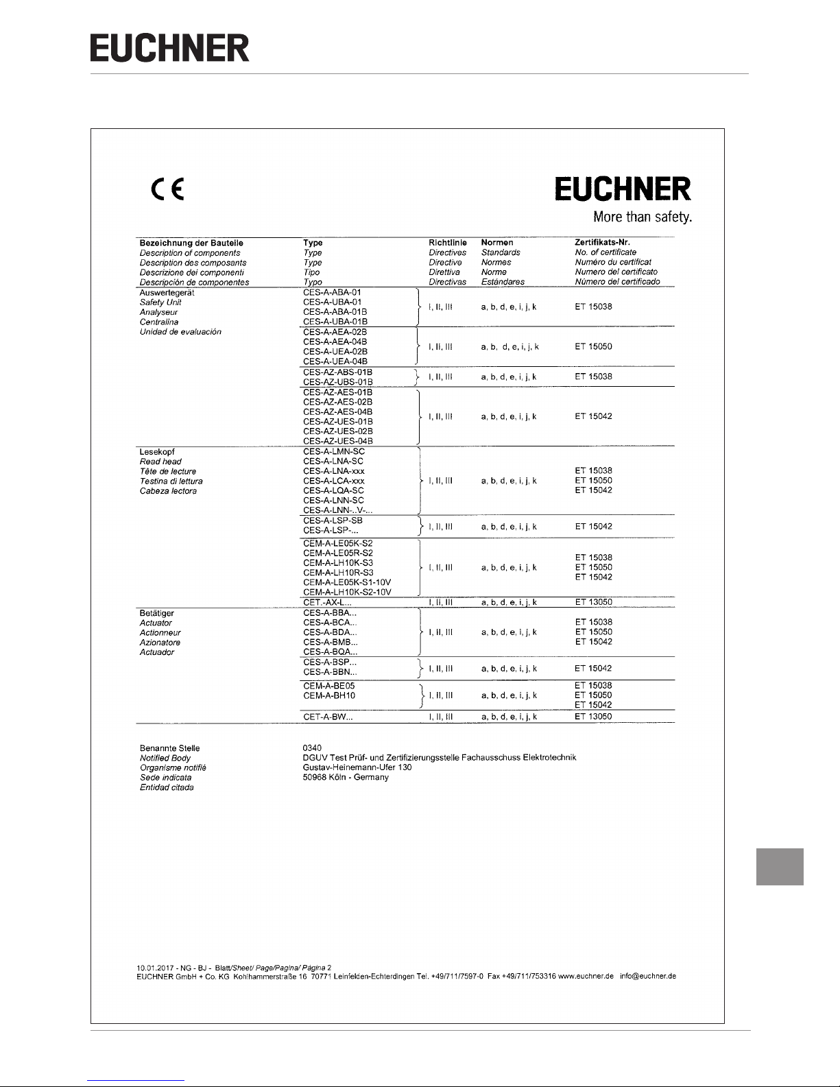
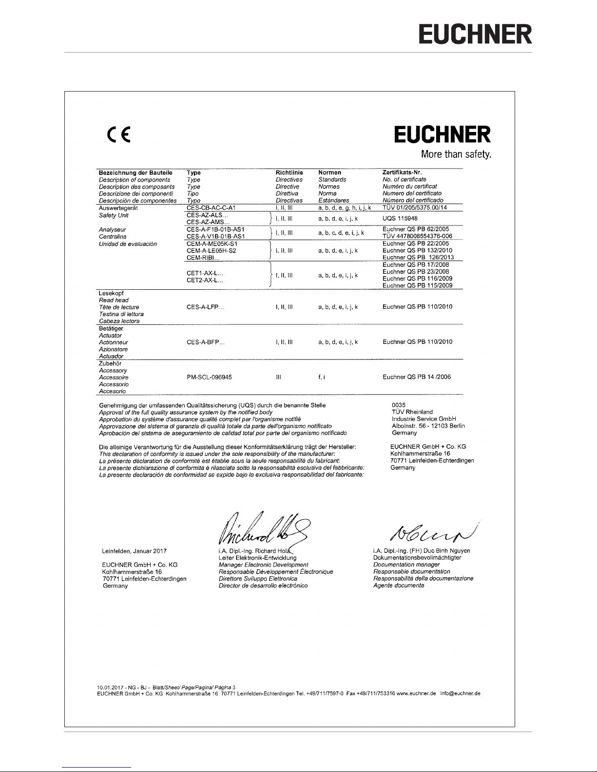
15. Declaration of conformity
Page 39
39
2084606-19-09/17 (translation of the original operating instructions)
Operating Instructions
Non-Contact Safety System CES-A-AEA-02B/CES-A-AEA-04B
EN
Page 40
Operating Instructions
Non-Contact Safety System CES-A-AEA-02B/CES-A-AEA-04B
40
(translation of the original operating instructions) 2084606-19-09/17
Page 41

41
2084606-19-09/17 (translation of the original operating instructions)
Operating Instructions
Non-Contact Safety System CES-A-AEA-02B/CES-A-AEA-04B
EN
Page 42

Operating Instructions
Non-Contact Safety System CES-A-AEA-02B/CES-A-AEA-04B
42
(translation of the original operating instructions) 2084606-19-09/17
Page 43

43
2084606-19-09/17 (translation of the original operating instructions)
Operating Instructions
Non-Contact Safety System CES-A-AEA-02B/CES-A-AEA-04B
EN
Page 44

EUCHNER GmbH + Co. KG
Kohlhammerstraße 16
70771 Leinfelden-Echterdingen
info@euchner.de
www.euchner.com
Edition:
2084606-19-09/17
Title:
Operating Instructions Non-Contact Safety System
CES-A-AEA-02B/CES-A-AEA-04B (Unicode)
(translation of the original operating instructions)
Copyright:
© EUCHNER GmbH + Co. KG, 09/2017
Subject to technical modications; no responsibility is accepted for the accuracy of this information.
 Loading...