

Page 1

Operating Instructions
Non-Contact Safety Switch
CES-A-C5H-EX Unicode/Multicode
EN
Page 2

Operating Instructions
Non-Contact Safety Switch CES-A-C5H-EX
Contents
1. About this document ............................................................................................. 4
1.1. Scope ............................................................................................................................................4
1.2. Target group ..................................................................................................................................4
1.3. Key to symbols ...............................................................................................................................4
1.4. Supplementary documents ..............................................................................................................4
2. Correct use .......................................................................................................... 5
3. Description of the safety function .......................................................................... 6
4. Explosion protection safety concept ...................................................................... 7
5. Exclusion of liability and warranty ......................................................................... 7
6. General safety precautions ................................................................................... 8
7. Function ............................................................................................................... 9
7.1. Door monitoring output ...................................................................................................................9
7.2. Switching states .............................................................................................................................9
7.3. Block diagram ..............................................................................................................................10
8. Changing the approach direction ........................................................................ 11
9. Mounting ............................................................................................................ 12
10. Electrical connection .......................................................................................... 14
10.1. Notes about .........................................................................................................................15
10.2. Safety in case of faults ..................................................................................................................15
10.3. Requirements for connection cables ...............................................................................................15
10.4. Connector assignment of safety switch CES-A-C5H-EX .....................................................................16
10.5. Correct connection .......................................................................................................................17
10.6. Connection example .....................................................................................................................18
11. Setup ................................................................................................................. 19
11.1. LED displays ................................................................................................................................19
11.2. Teach-in function for actuator (only for unicode evaluation) ...............................................................19
11.2.1. Carrying out teach-in for rst actuator (default setting on delivery) .......................................19
11.2.2. Carrying out teach-in for a new actuator ............................................................................20
11.3. Functional check ...........................................................................................................................20
12. System status table ............................................................................................ 21
2
(Translation of the original operating instructions) 2110182-09-12/18
Page 3

Operating Instructions
Non-Contact Safety Switch CES-A-C5H-EX
13. Technical data .................................................................................................... 22
13.1. Safety switch CES-A-C5H-EX ..........................................................................................................22
13.1.1. Technical data for safety switch CES-A-C5H-EX ...................................................................23
13.1.2. Typical system times ........................................................................................................24
13.2. Actuator CES-A-BPA-EX ..................................................................................................................25
13.2.1. Technical data .................................................................................................................25
13.2.2. Typical operating distance ................................................................................................26
13.2.3. Operating distance for center offset m = 0
13.3. Actuator CES-A-BBA-EX..................................................................................................................27
13.3.1. Technical data .................................................................................................................27
13.3.2. Typical operating distance ................................................................................................28
13.3.3. Operating distance for center offset m = 0
1) .............................................................................................26
1) .............................................................................................28
14. Ordering information and accessories ................................................................. 29
15. Inspection and service ........................................................................................ 29
16. Service .............................................................................................................. 29
17. Declaration of conformity ................................................................................... 30
2110182-09-12/18 (Translation of the original operating instructions)
EN
3
Page 4
Operating Instructions
Non-Contact Safety Switch CES-A-C5H-EX
1. About this document
1.1. Scope
These operating instructions are valid for all CES-A-C5H-EX. These operating instructions, the document “Safety information
and maintenance” and any enclosed data sheet form the complete user information for your device.
1.2. Target group
Design engineers and installation planners for safety devices on machines, as well as setup and servicing staff possessing
special expertise in handling safety components.
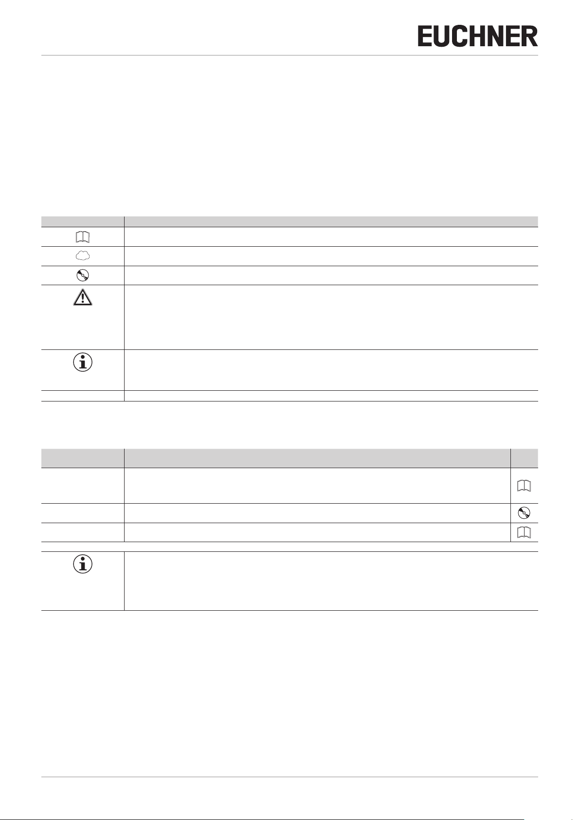
1.3. Key to symbols
Symbol/depiction Meaning
Printed document
www
DANGER
WARNING
Document is available for download at www.euchner.com
Document on CD
Safety precautions
Danger of death or severe injuries
Warning about possible injuries
Caution slight injuries possible
CAUTION
Notice about possible device damage
NOTICE
Important!
Tip Useful information
Important information
1.4. Supplementary documents
The overall documentation for this device consists of the following documents:
Document title
(document number)
Safety Information
and Maintenance
CES-A-C5H-EX
(2117077)
Operating Instructions
(2110182)
Possibly enclosed data
sheet
Contents
Basic information for safe setup and service
(this document)
Item-specic information about deviations or additions
Important!
Always read all documents to gain a complete overview of safe installation, setup and use of the
device. The documents can be downloaded from www.euchner.com. For this purpose enter the doc.
no. in the search box.
4
(Translation of the original operating instructions) 2110182-09-12/18
Page 5

Operating Instructions
Non-Contact Safety Switch CES-A-C5H-EX
2. Correct use
Safety switches series CES-A-C5H-EX are interlocking devices without guard locking (type4). The device meets the requirements according to ENIEC60947-5-3. Devices with unicode evaluation possess a high coding level, devices with multicode
evaluation possess a low coding level.
In combination with a movable guard and the machine control, this safety component prevents dangerous machine functions
from occurring while the guard is open. A stop command is triggered if the guard is opened during the dangerous machine
function.
This means:
Ì Starting commands that cause a dangerous machine function must become active only when the guard is closed.
Ì Opening the guard triggers a stop command.
Ì Closing a guard must not cause automatic starting of a dangerous machine function. A separate start command must
be issued. For exceptions, refer to ENISO12100 or relevant C-standards.
Before the device is used, a risk assessment must be performed on the machine, e.g. in accordance with the following
standards:
Ì ENISO13849-1
Ì ENISO12100
Ì IEC62061
Correct use includes observing the relevant requirements for installation and operation, particularly based on the following
standards:
Ì ENISO13849-1
Ì ENISO14119
Ì EN60204-1
Ì DIN EN1127-1
Ì EN60079-0
Ì EN60079-7
Ì EN60079-14
Ì EN60079-31
The safety switch must be used only in conjunction with the designated CES actuators from EUCHNER. On the use of different
actuators, EUCHNER provides no warranty for safe function.
Important!
Ì Devices with ATEX rating may be operated only with actuators that also have an ATEX rating for
the same zone.
Ì The user is responsible for the proper integration of the device into a safe overall system. For this
purpose, the overall system must be validated, e.g. in accordance with ENISO13849-2.
Ì It is only allowed to use components that are permissible in accordance with the table below.
2110182-09-12/18 (Translation of the original operating instructions)
EN
5
Page 6

Operating Instructions
Non-Contact Safety Switch CES-A-C5H-EX
Table 1: Possible combinations for CES components
Actuator
Safety switch
CES-A-C5H-EX
Combination possible
Combination possible, guard locking for process protection
Key to symbols
Combination possible, guard locking for personnel protection
Combination not permissible
Table 2: Associated connection cables
Designation Cable length [m] Order no./item
M12 connection cable, silicone-free PVC,
ying lead, 8-pin
CES-A-BBA-EX
5
10
15
20
25
50
098158
CES-A-BPA-EX
102125
C-M12F08-08X025PV05,0-GA-077751
C-M12F08-08X025PV10,0-GA-077752
C-M12F08-08X025PV15,0-GA-077753
C-M12F08-08X025PV20,0-GA-077871
C-M12F08-08X025PV25,0-GA-077872
C-M12F08-08X025PV50,0-GA-077873
077751
077752
077753
077871
077872
077873
3. Description of the safety function
Devices from this series feature the following safety functions:
Monitoring of the guard position
(interlocking device according to ENISO14119)
Ì Safety function:
- The safety outputs are switched off when the guard is open (see chapter 7.2. Switching states on page 9).
Ì Safety characteristics: category, Performance Level, PFH
(see chapter 13. Technical data on page 22).
D
6
(Translation of the original operating instructions) 2110182-09-12/18
Page 7
Operating Instructions
Non-Contact Safety Switch CES-A-C5H-EX
4. Explosion protection safety concept
Important!
Ì In order to achieve the explosion protection stated, all the conditions in the operating instructions
must be met. HIGH RISK product.
Ì Devices with ATEX rating may be operated only with actuators that also have an ATEX rating for
the same zone.
Ì Use connection components and connection cables from EUCHNER.
Ì The connecting cable must be laid such that it is protected against mechanical damage.
Ì In addition, a mechanical barrier is to be provided on the connecting cable as per EN60079-14,
section 9.3.9 to prevent ame propagation from the non-potentially explosive atmosphere to the
potentially explosive atmosphere.
II 3G Ex ic ec IIB T5 Gc X
II 3D Ex ic tc IIIC T90°C Dc X
…GcX = All the electrical connections must either be isolated from the mains supply by a safety transformer according to
IEC61558-2-6 with limited output voltage in the event of a fault, or by other equivalent isolation measures (PELV).
…DcX = To prevent electrostatic charging, do not subject the switch to any processes that generates a large amount of
charge.
Safety switches with ATEX identication marking from EUCHNER are not safety devices as dened by the ATEX
Directive.
The specied type of protection ic applies only to the integrated reader module. The electrical circuits in the device connection (M12 plug connector) are not intrinsically safe!
If mounted on heat/cooling sources, the permissible ambient temperature (see technical data) must be observed.
Ground the protective plate via the grounding terminal with a cable cross-section of 4mm² min. to prevent electrostatic
charging.
Protection against mechanical effects on the switch: to achieve the indicated explosion protection, it is essential the protective plate supplied is mounted (ESD protective paint).
On use in potentially explosive atmospheres, there is a danger of explosion due to electrical sparks.
Ì Never connect or disconnect connector when live.
If damage or wear is found, the complete switch and actuator assembly must be replaced. Replacement of individual parts
or assemblies is not permitted.
5. Exclusion of liability and warranty
In case of failure to comply with the conditions for correct use stated above, or if the safety instructions are not followed,
or if any servicing is not performed as required, liability will be excluded and the warranty void.
2110182-09-12/18 (Translation of the original operating instructions)
EN
7
Page 8
Operating Instructions
Non-Contact Safety Switch CES-A-C5H-EX
6. General safety precautions
Safety switches fulll personnel protection functions. Incorrect installation or tampering can lead to fatal injuries to personnel.
Check the safe function of the guard particularly
Ì after any setup work
Ì after the replacement of a system component
Ì after an extended period without use
Ì after every fault
Independent of these checks, the safe function of the guard should be checked at suitable intervals as part of the maintenance schedule.
DANGER
Danger of explosion due to sparks.
Ì Mounting, connection and maintenance are not allowed to be performed in a potentially explosive
atmosphere.
WARNING
Danger to life due to improper installation or due to bypassing (tampering). Safety components fulll
a personnel protection function.
Ì Safety components must not be bypassed, turned away, removed or otherwise rendered ineffec-
tive. On this topic pay attention in particular to the measures for reducing the possibility of bypassing according to ENISO14119:2013, section 7.
Ì The switching operation must be triggered only by actuators designated for this purpose.
Ì Prevent bypassing by means of replacement actuators (only for multicode evaluation). For this
purpose, restrict access to actuators and to keys for releases, for example.
Ì Mounting, electrical connection and setup only by authorized personnel possessing the following
knowledge:
- specialist knowledge in handling safety components
- knowledge about the applicable EMC regulations
- knowledge about the applicable regulations on occupational safety and accident prevention.
Important!
Prior to use, read the operating instructions and keep these in a safe place. Ensure the operating
instructions are always available during mounting, setup and servicing. EUCHNER cannot provide any
warranty in relation to the readability of the CD for the storage period required. For this reason you
should archive a printed copy of the operating instructions. You can download the operating instructions from www.euchner.com.
8
(Translation of the original operating instructions) 2110182-09-12/18
Page 9

Operating Instructions
Non-Contact Safety Switch CES-A-C5H-EX
7. Function
The safety switch monitors the position of movable guards. The safety outputs are switched on/off when the actuator is
moved to/removed from the operating distance.
The system consists of the following components: coded actuator (transponder) and switch.
Whether the device learns the complete actuator code (unicode) or not (multicode) depends on the respective version.
Ì Devices with unicode evaluation: The actuator must be assigned to the safety switch by a teach-in operation so that
it is detected by the system. This unambiguous assignment ensures a particularly high level of protection against tampering. The system thus possesses a high coding level.
Ì Devices with multicode evaluation: Unlike systems with unique code detection, on multicode devices a specic code
is not requested but instead it is only checked whether the actuator is of a type that can be detected by the system
(multicode detection). There is no exact comparison of the actuator code with the taught-in code in the safety switch
(unique code detection). The system possesses a low coding level.
When the guard is closed, the actuator is moved towards the safety switch. When the switch-on distance is reached, power
is supplied to the actuator by the switch and data are transferred.
If a permissible code is detected, the safety outputs are switched on.
The safety outputs are switched off when the guard is opened.
In the event of a fault in the safety switch, the safety outputs are switched off and the DIA LED illuminates red. The occurrence
of faults is detected at the latest on the next demand to close the safety outputs (e.g. on starting).
7.1. Door monitoring output
The door monitoring output is switched on as soon as a valid actuator is detected in the operating distance.
7.2. Switching states
The detailed switching states for your switch can be found in the system status table. All safety outputs, monitoring outputs
and display LEDs are described there.
(actuator in the operating distance and
Guard closed
permissible code detected)
(actuator not in the operating distance)
Guard open
Safety outputs LA and LB on off
Monitoring output OUT on off
2110182-09-12/18 (Translation of the original operating instructions)
EN
9
Page 10

Operating Instructions
Non-Contact Safety Switch CES-A-C5H-EX
7.3. Block diagram
Coded
actuator
Read head with
evaluation unit
CES-A-.5
Housing:
118 x 40 x 40 mm
Trans-
ponder
Read head
Output circuit:
+LA
LA
-LAB
Common ground for output A and B
Pin assignment:
Pin
1
2
3
4
5
6
7
8
Core color
WH/white
BN/brown
GN/green
YE/yellow
GY/gray
PK/pink
BU/blue
RD/red
R
Load A
Function
+
-
0V
+ U
LA
LB
OUT
+LA
-LAB
+LB
Power
supply
for load A
B
Connection:
M 12x1
8-pin, screened
Screen bonding clamp
The screen on the connection cable
is connected internally to the screen
bonding clamp on the housing.
(RD)
+LB
-LAB
(BU)
LB
(YE)
+LA
(PK)
(GN)
LA
(GY)
OUT
(BN)
+ U
B
(WH)
0V
dynamic signals
Test pulse 0
O1
0 V
I1
0 V
Test pulse 1
O9
0 V
I9
0 V
Input
E2
DC +24 V
0V
Safety PLC
with static /
Pulsed output
Safety input
Pulsed output
Safety input
Connection example with
safety PLC PSS 3056 (PILZ)
10
(Translation of the original operating instructions) 2110182-09-12/18
Page 11

Operating Instructions
Non-Contact Safety Switch CES-A-C5H-EX
8. Changing the approach direction
NOTICE
Risk of damage to equipment as a result of trapped cables.
Ì Make sure that the cables are not trapped or torn off when the approach direction is changed.
The active face of the read head can be adjusted in ve directions. It is marked by the red face.
The plug connector can be realigned in 45° steps to change the direction of the cable outlet (if elbow connectors are used).
1. Unscrew the screws on the fastening bracket.
2. Pull the read head from the fastening bracket and tilt the read head by 90° (arrow 2).
¨ The active face is now pointing downward.
3. Turn the read head by 180° (arrow 3).
4. Re-tighten the screws for the read head on the fastening bracket. Tightening torque 0.6 Nm.
Housing
Fastening bracket
Active face
Read head
5. Remove the clip from the underside of the housing to change the lateral approach direction.
6. Pull the read head off the housing and turn it in 90° steps in the desired approach direction.
7. Fit the read head to the housing and re-t the clip.
Clip
Housing
Read head
Other approach directions
2110182-09-12/18 (Translation of the original operating instructions)
EN
11
Page 12

Operating Instructions
min. 80mm
Operating
distance
Actuator
Operating
distance
Actuator
Flush mounting
Surface maounting
Non-Contact Safety Switch CES-A-C5H-EX
9. Mounting
WARNING
On use in potentially explosive atmospheres the following applies:
Ì Protection against mechanical effects on the switch:
- Install switch so that the rear of the housing is entirely covered in order to protect it from mechanical damage through impact.
CAUTION
Safety switches must not be bypassed (bridging of contacts), turned away, removed or otherwise
rendered ineffective.
Ì Observe ENISO14119:2013, section 7, for information about reducing the possibilities for by-
passing an interlocking device.
NOTICE
Risk of damage to equipment and malfunctions as a result of incorrect installation.
Ì Safety switches and actuators must not be used as an end stop.
Ì Observe ENISO14119:2013, sections 5.2 and 5.3, for information about fastening the safety
switch and the actuator.
Ì From the assured switch-off distance S
Ì When mounting several safety switches, observe the stipulated minimum distance to avoid mutual
interference.
, the safety outputs are safely shut down.
ar
.
Ì If the actuator is installed ush, the switching distance changes as a function of the installation
depth and the guard material.
12
(Translation of the original operating instructions) 2110182-09-12/18
Page 13

Operating Instructions
Non-Contact Safety Switch CES-A-C5H-EX
Note the following points:
Ì Actuator and safety switch must be easily accessible for inspection and replacement.
Ì Actuator and safety switch must be tted so that
- the front faces are at the minimum switch-on distance 0.8xSao or closer when the guard is closed. To avoid entering
the area of possible side lobes, a minimum distance is to be maintained in case of a side approach direction. See
chapter 13. Technical data, section Typical operating distance for the related actuator.
- when the guard is open up to the distance Sar (assured switch-off distance), a hazard is excluded.
- the actuator is positively mounted on the guard, e.g. by using the safety screws included.
- they cannot be removed or tampered with using simple means.
Ì Pay attention to the maximum tightening torque for the read head or safety switch and actuator fastenings of 1Nm. For
read heads/actuators made of PE-HD, the maximum tightening torque is only 0.5Nm.
2110182-09-12/18 (Translation of the original operating instructions)
EN
13
Page 14

Operating Instructions
+UB
0 V OUT
0 V
+24 V
+LA
LA
+LB
LB
-LAB
S11
S12
S22
S21
A2
A1
CES-A-.5
Non-Contact Safety Switch CES-A-C5H-EX
10. Electrical connection
WARNING
Loss of the safety function due to incorrect connection.
Ì Not suitable for safety relays that realize short-circuit monitoring with different potentials (0 V/24
V). The voltage at +LA/+LB must correspond to the information in the technical data.
Ì
WARNING
If there is a mistake, loss of the safety function due to incorrect connection.
Ì To ensure safety, both safety outputs must always be evaluated.
Ì Monitoring outputs must not be used as safety outputs.
Ì Lay the connection cables with protection to prevent the risk of short circuits.
WARNING
On use in potentially explosive atmospheres, there is a danger of explosion due to electrical sparks.
Ì Never connect or disconnect connector when live.
Ì Never apply electrical power to open connectors!
Ì Protection against mechanical effects on the switch:
- The connecting cable must be laid such that it is protected against mechanical damage.
- The connection cable must be laid rigidly; it is not permissible to lay the cable so that it can
move (e.g. in a drag chain).
- All the electrical connections must either be isolated from the mains supply by a safety transformer according to IEC 61558-2-6 with limited output voltage in the event of a fault, or by other
equivalent isolation measures (PELV).
CAUTION
Risk of damage to equipment or malfunctions as a result of incorrect connection.
Ì The inputs on an evaluation unit connected must be positive-switching, as the two outputs on the
safety switch deliver a level of +24V in the switched-on state.
Ì All electrical outputs must have an adequate protective circuit for inductive loads. The outputs
must be protected with a free-wheeling diode for this purpose. RC interference suppression units
must not be used.
Ì Power devices which are a powerful source of interference must be installed in a separate location
away from the input and output circuits for signal processing. The cable routing for safety circuits
should be as far away as possible from the cables of the power circuits.
Ì To avoid EMC interference, the physical environmental and operating conditions at the in-
stallation site of the device must comply with the requirements according to the standard
EN60204-1:2006, section 4.4.2 (EMC).
14
(Translation of the original operating instructions) 2110182-09-12/18
Page 15

CAUTION
Ì Please pay attention to any interference elds from devices such as frequency converters or
induction heating systems. Observe the EMC instructions in the manuals from the respective manufacturer.
Important!
Ì If the device does not appear to function when operating voltage is applied (e.g. green STATE LED
does not illuminate or ash), the safety switch must be returned unopened to the manufacturer.
Ì The device is fully encapsulated, it is therefore not possible to remove the lid from the housing.
10.1. Notes about
Important!
Ì For use and operation as per the requirements, a power supply with the feature “for use in
class 2 circuits” must be used.
Alternative solutions must comply with the following requirements:
- Electrically isolated power supply unit in combination with fuse as per UL248. This fuse should be
designed for max. 3.3A and should be integrated into the 30VDC voltage section.
Ì For use and applications as per the requirements of
category code CYJV2 or CYJV must be used.
Operating Instructions
Non-Contact Safety Switch CES-A-C5H-EX
1)
, a connection cable listed under the UL
1) Note on the scope of the UL approval: the devices have been tested as per the requirements of UL508 and CSA/ C22.2 no. 14 (protection against electric shock
and re).
10.2. Safety in case of faults
Ì The operating voltage U
Ì The contacts LA/LB and -LA/-LB are short circuit-proof, but they are not reverse polarity protected.
Ì A short circuit between LA and LB can only be detected by external pulsing.
Ì A short circuit in the cable can be excluded by laying the cable with protection.
is reverse polarity protected.
B
10.3. Requirements for connection cables
CAUTION
Danger of explosion or malfunctions as a result of incorrect connection cables.
Ì For connecting cables, the requirements in the following table apply. EUCHNER provides no war-
ranty for safe function in case of failure to comply with these requirements.
Ì The device meets the necessary EMC regulations even with an unscreened connection cable. For applications that are
particularly sensitive to interference, a screened cable can be connected to the screen bonding clamp. Via the protective plate the screen bonding clamp is electrically connected to the grounding terminal. The screen at the open end of
the cable must also be connected electrically to the machine ground.
Ì On the usage of a screened cable connected at both ends, it must be ensured that both ends are connected to a com-
mon earthing (and equipotential bonding) system according to EN620079-14. If necessary, an equipotential bonding
cable must be laid.
2110182-09-12/18 (Translation of the original operating instructions)
EN
15
Page 16

Operating Instructions
Non-Contact Safety Switch CES-A-C5H-EX
Observe the following requirements with respect to the connection cables:
Table 3: Voltage drop as a function of switching current and cable length (examples)
Switching current Cable length "l" Voltage drop Max. voltage drop Max. voltage drop
[mA] [m] Output [V] Cable [V] Total [V]
(safety control system with
6
pulsed signals)
50
(safety relay)
100
(e.g. small contactor)
1 -100 1.4 0.1 1.5
101 - 300 1.4 0.4 1.8
1 - 15 1.5 0.2 1.7
16 - 50 1.5 0.5 2.0
51 - 100
101 - 300 1.5 3.0 3.5
1 - 15 1.7 0.4 2.1
16 - 50 1.7 1.0 2.7
51 - 100 1.7 2.0 3.7
101 - 300
1.5 1.0
1.7 6.0
10.4. Connector assignment of safety switch CES-A-C5H-EX
2.5
7.7
1 0 V 5 OUT
2 + UB 6 +LA
3 LA 7 -LAB
4 LB 8 +LB
5
6
7
8
4
3
21
View of connection side of the device
The screen on the connection cable is connected
internally to the device screen bonding clamp via the
knurled nut on the M12 plug connector.
Figure 1: Connector assignment of safety switch CES-A-C5H-EX
16
(Translation of the original operating instructions) 2110182-09-12/18
Page 17
10.5. Correct connection
WARNING
If there is a mistake, loss of the safety function due to incorrect connection.
Ì To ensure safety, both safety outputs (LA and LB) must always be evaluated.
Ì To achieve category 3/4 according to EN ISO 13849-1, it is necessary to monitor the downstream
contactors.
B
CES-A-C5...
0 V
+U
Monitoring output
(no safety fnction!)
OUT
-LAB
Non-Contact Safety Switch CES-A-C5H-EX
Safety output LB
LB
+LB
Safety outpu LA
LA
Operating Instructions
+LA
+ 24 V
To the
control system
+ 24 V
Application
M
+ 24 V
2110182-09-12/18 (Translation of the original operating instructions)
EN
17
Page 18

Operating Instructions
Non-Contact Safety Switch CES-A-C5H-EX
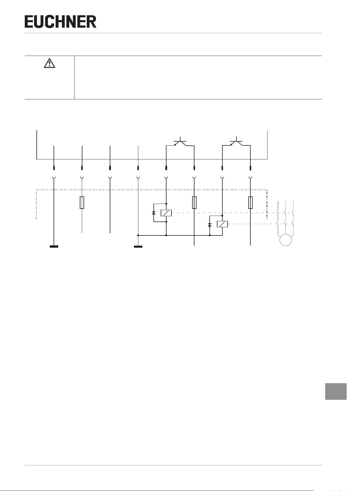
10.6. Connection example
Important!
Ì To achieve category 4 according to EN ISO 13849-1, it is necessary to monitor the downstream
contactors (not shown here).
Ì The example shows only an excerpt that is relevant for connection of the CES system. The exam-
ple illustrated here does not show complete system planning. The user is responsible for safe integration into the overall system. Detailed application examples can be found at www.euchner.com.
Simply enter the order number in the search box. All available connection examples for the device
can be found in “Downloads.”
+24V DC
-F1
Power Supply
Safety - PLC with static /
dynamic signals
O1 Pulsed output
O2 Pulsed output
I1 Input
I2 Input
A1
6
+LA
LA
3
8
+LB
LB
4
EUCH NER
+24V DC
-F2
-LAB
7
0V
1
2
+UB
Read head
OUT
5
GND
Figure 2: Connection example for CES-A-C5H-EX
18
GND
(Translation of the original operating instructions) 2110182-09-12/18
Page 19

11. Setup
11.1. LED displays
LED Color State Meaning
illuminated
STATE green
ashing
Normal operation
- Teach-in operation
(for further signal function, see chapter 12. System status table on page 21)
Operating Instructions
Non-Contact Safety Switch CES-A-C5H-EX
yellow
OUT/ERROR
red
illuminated
illuminated
Valid actuator detected
- Internal electronics fault
- Invalid teach-in operation
(for further signal function, see chapter 12. System status table on page 21)
11.2. Teach-in function for actuator (only for unicode evaluation)
The actuator must be assigned to the evaluation unit using a teach-in function before the system forms a functional unit.
During the teach-in operation the safety outputs are open and the door monitoring output is LOW. The system is in the safe
state.
Important!
Ì During the teach-in operation the following conditions must be met:
- No state change, e.g. opening of a safety door.
- The power supply must not be switched off.
Ì If these conditions are not met, the evaluation unit switches to the safe fault state (ERROR LED
illuminates) and signals this operating fault with the STATE LED.
Ì The number of teach-in operations on one evaluation unit is limited to a maximum of 8.
Ì The evaluation unit can only be operated with the last actuator taught
Ì An actuator that has not been subjected to teach-in will not be detected by the related read head.
Ì When the evaluation unit is switched on (operating voltage is applied), the STATE LED signals the
number of possible remaining teach-in operations (see System status table)
Ì After the eighth teach-in operation or if an “old” actuator is placed against the read head, the sys-
tem automatically switches to the teach-in mode. In both cases, a teach-in operation with a duration of 60 seconds is started; however, the last actuator code remains active (see System status
table) in the memory – a new code is not taught.
11.2.1. Carrying out teach-in for rst actuator (default setting on delivery)
To trigger the rst teach-in operation, the user must perform the following actions in the stipulated order:
1. Start teach-in operation
- Switch on operating voltage (STATE LED ashes at approx. 4Hz)
- Close door to be monitored (the actuator must be in the operating distance of the read head)
- Teach-in operation starts (STATE LED ashes at approx. 1Hz)
- Wait for acknowledgment of the teach-in operation (STATE LED goes out after approx. 60 seconds)
2. End teach-in operation
- Interrupt operating voltage for at least 3 seconds (code for the actuator taught-in is activated)
3. Check guard for effectiveness
2110182-09-12/18 (Translation of the original operating instructions)
EN
19
Page 20

Operating Instructions
Non-Contact Safety Switch CES-A-C5H-EX
11.2.2. Carrying out teach-in for a new actuator
A maximum of eight teach-in operations can be undertaken. The number of already completed teach-in operations is signaled
by the ashing sequence of the STATE LED each time the power supply is connected (see 12. System status table on page
21, area Status indication).
Faulty actuators can be replaced. Then a complete teach-in operation must be performed as per this section.
To trigger a further teach-in operation, the user must perform the following actions in the stipulated order:
1. Start teach-in operation
- Switch on operating voltage
- Close door to be monitored (the new actuator must be in the operating distance of the read head)
- Teach-in operation starts (STATE LED ashes at approx. 1Hz)
- Wait for acknowledgment of the teach-in operation (STATE LED goes out after approx. 60 seconds)
2. End teach-in operation
- Interrupt operating voltage for at least 3 seconds (code for the new actuator taught-in is activated)
The newly taught-in actuator is saved and the old actuator deactivated.
3. Check guard for effectiveness
11.3. Functional check
After installation and any fault, the safety function must be fully checked. Proceed as follows:
WARNING
Danger of fatal injury as a result of faults in installation and functional check.
Ì Before carrying out the functional check, make sure that there are no persons in the danger zone.
Ì Observe the valid accident prevention regulations.
1. Switch on operating voltage.
- The safety switch carries out a self-test.
The green STATE LED ashes up to three times.
The STATE LED then illuminates continuously.
The OUT and ERROR LEDs do not light up.
2. Close all guards.
- The machine must not start automatically.
- The green STATE LED and the yellow OUT LED light up continuously.
3. Enable operation in the control system.
4. Open the guard.
- The machine must switch off and it must not be possible to start it as long as the guard is open.
- The green STATE LED illuminates continuously; the OUT and ERROR LEDs do not illuminate.
Repeat steps 2…4 separately for each guard.
20
(Translation of the original operating instructions) 2110182-09-12/18
Page 21

12. System status table
Operating Instructions
Non-Contact Safety Switch CES-A-C5H-EX
PLC
Output
Operating mode
Actuator/door position
Safety outputs LA and LB
closed on 1 Normal operation, door closed
Normal operation
open off 0 Normal operation, door open
open off 0 4 Hz Initial setup after delivery, ready for rst teach-in operation
Teach-in operation
(unicode only)
State indication
(unicode only)
Fault display X off 0
closed off 0
closed off 0
X off 0
X off 0
X off 0
X off 0 Device cannot perform any further teach-in operation
closed off 0
LED indicator
OUT (status signal)
3 x +
2 x +
1 x +
STATE (green)
1 Hz
(60 s)
Output
1 x
OUT/ERROR
State
(yellow)
OUT/ERROR (red)
Teach-in operation
Positive acknowledgment of completion of teach-in operation.
To activate the actuator code from the teach-in operation in the evaluation
unit, the operating voltage must then be switched off at the evaluation unit
for min. 3 seconds.
Indication after 1st to 5th teach-in operation
Indication of the remaining teach-in operations after the 6th teach-in operation
Indication of the remaining teach-in operations after the 7th teach-in operation
Device-internal component failure or
excessively high interference (EMC) or short circuit/external power at the
LA/LB safety output
Incorrect 9th teach-in operation (unicode only)
Operating fault
(unicode only)
Key to symbols
closed off 0
closed off 0
N 0 Volt or not connected
1 24 Volt
0 0 Volt
15 Hz (8 s)
3 x +
3 x
X Any state
2 x
3 x Negative acknowledgment for teach-in operation. Actuator was held in front
Incorrect teach-in operation for an old actuator (unicode only)
of the read head for less than 60 s
LED not illuminated
LED illuminated
LED ashes for 8 seconds at 15 Hz
LED ashes three times and then illuminates continuously
LED ashes three times, and this is then repeated
After the cause has been remedied, faults can generally be reset by opening and closing the guard. If the fault is still displayed
afterward, briey interrupt the power supply. Please contact the manufacturer if the fault could not be reset after restarting.
Important!
If you do not nd the displayed device status in the system status table, this indicates an internal device
fault. In this case, you should contact the manufacturer.
EN
2110182-09-12/18 (Translation of the original operating instructions)
21
Page 22

Operating Instructions
46
57,5
24 VOUT
24 V
OUT
Non-Contact Safety Switch CES-A-C5H-EX
13. Technical data
NOTICE
If a data sheet is included with the product, the information on the data sheet applies.
13.1.
Safety switch CES-A-C5H-EX
Ì Read head and evaluation unit integrated in the normal housing
Ì Semiconductor output
Ì M12 plug connector
ATEX rating
II 3G Ex ic ec IIB T5 Gc X
II 3D Ex ic tc IIIC T90°C Dc X
Dimension drawing
46
7,3
LED GN
LED RD/YE
Active face Active face
40 40
40
45,5 60
Ø 5,3
±0,1
165
Approvals
118
Protective plate
Grounding terminal
Ground the protective plate via cable
to prevent electrostatic charging.
Cable cross-section 4…6 mm²
Switching characteristics
Ì 2 safety outputs
(semiconductor outputs)
Ì One door monitoring output
(semiconductor output, not a safety
output)
13
M12x1
44,5
34,5
y
30
±0,1
LA
LB
Guard
(actuator not in the operating
open
distance)
+LA LA
+LB LB
closed
(actuator detected)
Read head Actuator Read head
+LA
+LB
22
(Translation of the original operating instructions) 2110182-09-12/18
Page 23

13.1.1. Technical data for safety switch CES-A-C5H-EX
Operating Instructions
Non-Contact Safety Switch CES-A-C5H-EX
Parameter
Housing material PBT GF30
Dimensions According to EN 60947-5-2 mm
Weight 0.4 kg
Ambient temperature at UB = DC 24 V -20 - +50 °C
Degree of protection IP65/IP67
Degree of contamination 3
Rated insulation voltage U
Rated impulse withstand voltage U
Rated conditional short-circuit current 100 A
Resilience to vibration According to EN 60947-5-2
Installation position Any
Connection M12 plug connector, 8-pin, screen can be applied
Operating voltage UB (regulated, residual ripple < 5%) 21 24 27 V DC
For the approval according to UL the following applies Operation only with UL class 2 power supply or equivalent measures
Current consumption 80 mA
Switching load according to UL max. DC 24 V, class 2
External fuse (operating voltage UB) 0.25 - 8 A
Power supply for load U(+LA)/U(+LB) 18 - 27 V DC
Safety outputs (LA/LB, 2 semiconductor outputs, p-switching,
short circuit-proof, electrically decoupled)
- Output voltage U(LA/U(LB)
HIGH U(LA) U(+LA) - 1.5 - U(+LA)
HIGH U(LB) U(+LB) - 1.5 - U(+LB) V DC
LOW U(LA)/U(LB) 0 - 1
Switching current per safety output 1 - 100 mA
External fuse (U(+LA)/U(+LB), safety circuit 100 mA medium slow-blow
Utilization category according to EN 60947-5-2 DC-13 24 V 100 mA
Monitoring output (OUT, semiconductor output, p-switching,
short circuit-proof)
- Output voltage 0.8 x U
- Max. load - - 20 mA
3)
Risk time
Discrepancy time - - 120 ms
Ready delay
Dwell time
Switching frequency - - 1 Hz
Repeat accuracy R acc. to EN IEC 60947-5-3 ≤ 10 %
Mounting distance between 2 read heads or 2 actuators 80 - - mm
EMC protection requirements Acc. to EN 60947-5-3
LED displays STATE LED green: Normal operation
Reliability values acc. to EN ISO 13849-1
Category 4
Performance Level (PL) PL e
PFH
Diagnostic coverage DC 99 %
MTTF
Mission time 20 years
1) Tested by employers’ liability insurance association up to 75 V.
2) Values at a switching current of 50 mA without taking into account the cable length.
3) Maximum switch-off delay for the safety outputs following removal of the actuator.
4) After the operating voltage is switched on, the semiconductor outputs are switched off and the monitoring outputs are set LOW during the ready delay.
5) The dwell time of an actuator inside and outside the operating distance must be at least 0.5 s to ensure reliable detection of internal faults in the evaluation unit (self-monitoring).
4)
5)
D
D
i
imp
2)
Flashing: Teach-in operation
OUT/ERROR LED yellow: Actuator detected
OUT/ERROR LED red: - EMC interference
- Internal electronics fault
- Invalid teach-in operation
min. typ. max.
- - 300
- - 1.5 kV
B
- - 180 ms
- - 3 s
0.5 - - s
Value
1)
- U
3.7 x 10⁻⁹ / h
644 years
B
Unit
V DC
V
EN
2110182-09-12/18 (Translation of the original operating instructions)
23
Page 24

Operating Instructions
Non-Contact Safety Switch CES-A-C5H-EX
13.1.2. Typical system times
Please refer to the technical data for the exact values.
Ready delay: After switching on, the device carries out a self-test. The system is ready for operation only after this time.
Switch-on time of safety outputs: The max. reaction time ton is the time from the moment when the actuator is in the
operating distance to the moment when the safety outputs switch on. This time corresponds to the risk time.
Risk time according to EN 60947-5-3: If an actuator moves outside the operating distance, the safety outputs (LA and
LB) are switched off no later than after the risk time.
Discrepancy time: The safety outputs (LA and LB) switch with a slight time offset. They have the same signal state no
later than after the discrepancy time.
24
(Translation of the original operating instructions) 2110182-09-12/18
Page 25

13.2. Actuator CES-A-BPA-EX
Ì Cube-shaped design 40x40mm
ATEX rating
II 3G Ex ic IIC T6 Gc
II 3D Ex ic IIIC T85°C Dc X
Dimension drawing for CES-A-BPA-EX
0
- 0,25
40
CES-A-BPA-EX
±0,1
30
Operating Instructions
Non-Contact Safety Switch CES-A-C5H-EX
10
4
Ø 5,2
CD
IP67
Active face
2 safety screws M4 x 14
included
Active face
13.2.1. Technical data
Parameter
Housing material PBT GF30
Dimensions 40x40x10 mm
Weight 0.025 kg
Ambient temperature -25 - +70 °C
Degree of protection IP65/IP67/IP69K
Installation position Active face opposite read head
Power supply Inductive via read head
min. typ. max.
Value
Unit
2110182-09-12/18 (Translation of the original operating instructions)
EN
25
Page 26

Operating Instructions
Non-Contact Safety Switch CES-A-C5H-EX
13.2.2. Typical operating distance
Only in conjunction with actuator CES-A-BPA-EX on surface mounting.
Y
45
40
35
-45
20
25
30
35
40
45
X
30
25
20
15
10
5
5
10
15
5
10
15
20
25
30
35
40
45
Z
-45
For a side approach direction for the actuator and read head, a minimum distance of s = 6 mm must be maintained so that the
13.2.3. Operating distance for center offset m = 0
Parameter
Switch-on distance - 22
Assured switch-on distance S
Switching hysteresis 1 2 -
Assured switch-off distance S
1) On surface mounting on aluminum; in a non-metallic environment the typical switching distance increases to 30 mm.
operating distance of the side lobes is not entered.
ao
ar
1)
Value
min. typ. max.
1)
15 - -
- - 58
Unit
-
mm
26
(Translation of the original operating instructions) 2110182-09-12/18
Page 27

13.3. Actuator CES-A-BBA-EX
Ì Cube-shaped design 42x25mm
ATEX rating
II 3G Ex ic IIC T6 Gc
II 3D Ex ic IIIC T85°C Dc X
Operating Instructions
Non-Contact Safety Switch CES-A-C5H-EX
Dimension drawing for CES-A-BBA-EX
2 safety screws M4X14
included
42
CES-A-B BA-EX
±0,1
32
25
Active face
12
ø4,5
4,6
ø8
Active face
Approvals
13.3.1. Technical data
Parameter
Housing material Fortron, reinforced thermoplastic, fully encapsulated
Dimensions 42x25x12 mm
Weight 0.02 kg
Ambient temperature -25 - +70 °C
Degree of protection IP65/IP67/IP69K
Installation position Active face opposite read head
Power supply Inductive via read head
min. typ. max.
Value
Unit
2110182-09-12/18 (Translation of the original operating instructions)
EN
27
Page 28

Operating Instructions
Non-Contact Safety Switch CES-A-C5H-EX
13.3.2. Typical operating distance
Only in combination with actuator CES-A-BBA-EX.
Y
30
25
-30
15
20
25
X
20
15
10
5
5
10
5
10
-30
15
20
25
30
Z
For a side approach direction for the actuator and safety switch, a minimum distance of s = 4 mm must be maintained so that the
13.3.3. Operating distance for center offset m = 0
Parameter
Assured switch-on distance S
operating distance of the side lobes is not entered.
ao
1)
Value
min. typ. max.
18 - -
Switch-on distance - 20 -
Switching hysteresis 2 3 -
Assured switch-off distance S
ar
- - 40
1) The values apply to surface mounting of the actuator.
Unit
mm
28
(Translation of the original operating instructions) 2110182-09-12/18
Page 29

14. Ordering information and accessories
Tip!
Suitable accessories, e.g. cables or assembly material, can be found at www.euchner.com. To order,
enter the order number of your item in the search box and open the item view. Accessories that can
be combined with the item are listed in “Accessories.”
15. Inspection and service
WARNING
Loss of the safety function and danger of explosion due to damage to the system.
Ì In case of damage, the entire device must be replaced.
Ì Only accessories or spare parts that can be ordered from EUCHNER may be replaced.
WARNING
Danger of explosion due to electrostatic charging.
Ì Always use a damp cloth or a special anti-static cloth during cleaning work.
Ì The device must not be subjected to any processes that generate a large amount of charge.
Operating Instructions
Non-Contact Safety Switch CES-A-C5H-EX
Regular inspection of the following is necessary to ensure trouble-free long-term operation:
Ì Check the switching function (see chapter 11.3. Functional check on page 20)
Ì Check the secure fastening of the devices and the connections
Ì Check for soiling
No servicing is required. Repairs to the device are only allowed to be made by the manufacturer.
NOTICE
The year of manufacture can be seen in the lower right corner of the type label.
16. Service
If service support is required, please contact:
EUCHNER GmbH + Co. KG
Kohlhammerstraße 16
70771 Leinfelden-Echterdingen
Service telephone:
+49 711 7597-500
E-mail:
support@euchner.de
Internet:
www.euchner.com
2110182-09-12/18 (Translation of the original operating instructions)
EN
29
Page 30

Operating Instructions
Non-Contact Safety Switch CES-A-C5H-EX
17. Declaration of conformity
30
(Translation of the original operating instructions) 2110182-09-12/18
Page 31

Operating Instructions
Non-Contact Safety Switch CES-A-C5H-EX
2110182-09-12/18 (Translation of the original operating instructions)
EN
31
Page 32

Euchner GmbH + Co. KG
Kohlhammerstraße 16
70771 Leinfelden-Echterdingen
info@euchner.de
www.euchner.com
Edition:
2110182-09-12/18
Title:
Operating Instructions Non-Contact Safety Switch
CES-A-C5H-EX
(Translation of the original operating instructions)
Copyright:
© EUCHNER GmbH + Co. KG, 12/2018
Subject to technical modications; no responsibility is accepted for the accuracy of this information.
 Loading...