

Page 1

AS-Interface Safety at Work
Quick Reference
Page 2

Directory
1 EUCHNER Safety Parts ..................................................................................... 3
1.1 Parameters for all EUCHNER electromechanical safety switches, non-contact
safety system and enabling switches ................................................................................. 3
1.2 Failure programming an AS-i address of EUCHNER safety switch .......................... 4
1.3 States of ASi safety parts ........................................................................................ 5
2 SFM Safety Monitor ........................................................................................... 6
2.1 Password forgotten or lost ....................................................................................... 6
2.2 Delete Safety Monitor .............................................................................................. 7
2.3 Replacing a defective Slave (without teach-in of actuator) ...................................... 8
2.4 Replacing a defective Slave (with teach-in of actuator) ........................................... 9
2.5 Replacing a defective Monitor ................................................................................10
2.6 Cable pin configuration for safety monitor ..............................................................11
2.7 Faults shown at monitor and solution .....................................................................12
3 GMOX Safety Monitor ...................................................................................... 14
3.1 Password forgotten or lost ......................................................................................14
3.2 Delete Safety Monitor .............................................................................................17
3.3 Slave-Address-Tool in the Safety Monitor ..............................................................18
3.4 Replacing a defective slave (without teach-in of actuator) ......................................19
3.5 Replacing a defective slave (with teach-in of actuator) ...........................................20
3.6 Reset Safety Error (caused by exchange of a safety slave) ....................................21
3.7 Replacing a defective AS-i Safety Monitor ..............................................................23
3.8 Set outputs of the slaves ........................................................................................25
3.9 Diagnostics of slaves in Safety Monitor ..................................................................26
3.10 Cable pin configuration for GMOX ..........................................................................27
3.11 Fatal Errors ............................................................................................................28
3.12 States of GMOX Safety Monitor .............................................................................30
4 Software ASiMon ............................................................................................. 31
4.1 Diagnostics with Software ASiMon .........................................................................31
4.2 State of AS-i Safety Switches ................................................................ .................32
Safety Monitors - AS-i Quick Reference - 08/2014 2
Page 3
IO Code: 7
ID Code: B
ID 1: F
ID 2: E
IO Code: 0
ID Code: B
ID 1: F
ID 2: E
1 EUCHNER Safety Parts
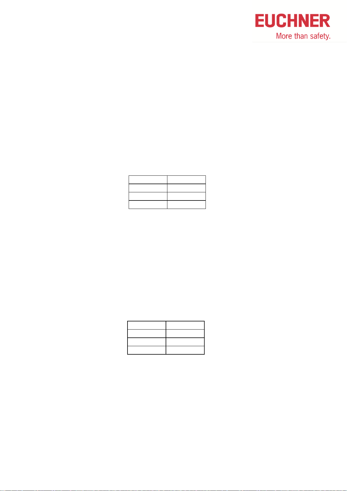
1.1 Parameters for all EUCHNER electromechanical safety
switches, non-contact safety system and enabling switches
Parameters for all electromechanical safety switches with and without locking and
non-contact safety switches CESx1 (094230 + 096631)
Safe slaves are built according to Specification 2.11 for standard slaves
All parameters of safety switches are pre-programmed at delivery and can be read with a
programming device.
The following values are adjusted:
Parameters for enabling switches and non-contacts safety switches CESx4 (097660 +
100206)
Safe slaves are built according to Specification 2.11 for standard slaves
All parameters of safety switches and enabling switches are pre-programmed at delivery and
can be read with a programming device.
The following values are adjusted:
Safety Monitors - AS-i Quick Reference - 08/2014 3
Page 4

1.2 Failure programming an AS-i address of EUCHNER safety
switch
With a Schneider AS-i address programming device type ASI TERV 2 or Siemens handheld
device type 3RK1 904-2AB00 a failure can occur in programming an EUCHNER AS-i safety
switch with M12 connector.
The display of the handheld shows: dblAdd Duplicate Address
Workaround: use an M12 cable where only pins 1 and 3 are used (AS-i + and AS-I - )
Safety Monitors - AS-i Quick Reference - 08/2014 4
Page 5
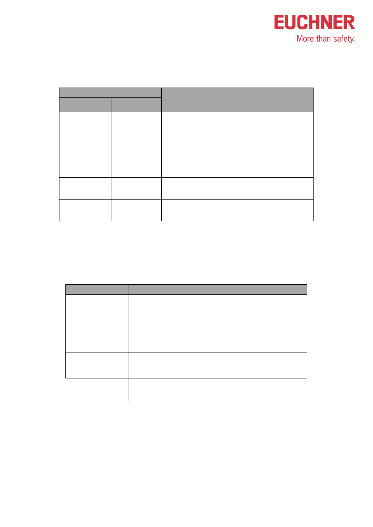
LED State
Description
ASI
green
Fault or State
red
on
off
Normal operation
AS-Interface power connected
on
on
No data transfer between master and slave.
Reason:
- Master in STOP-Mode
- Slave not in LPS
- Slave with wrong IO/ID
- Reset at slave active
blinking *
on
No data transfer between master and slave.
Reason: Slave-Address = 0
blinking or on
blinking * Device failure in slave.
Please contact EUCHNER.
State LED ASI
Description
Green
Normal operation
Red No data transfer between master and slave.
Reason:
- Master in STOP-Mode
- Slave not in LPS
- Slave with wrong IO/ID
Red / Yellow
Alternately blinking
No data transfer between master and slave.
Reason: Slave-Address = 0
Red/green
Alternately blinking
Red blinking
Auxiliary power not connected or device failure in slave.
Please contact EUCHNER.
1.3 States of ASi safety parts
* Blinking LEDs are not supported from all safety switches
LPS List Projected Slaves
IO/ID Slave profile to identify a slaves (Defined by manufacturer)
CET:
Safety Monitors - AS-i Quick Reference - 08/2014 5
Page 6
2 SFM Safety Monitor
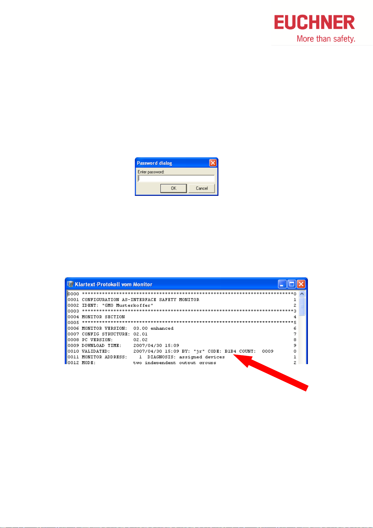
2.1 Password forgotten or lost
Read-out of the configuration from a monitor without password
1. Remove the AS-I cable from the monitor
2. Connect the ASiMon software PC to the monitor
3. In the ASi-Mon software under the menu item monitor >> Stop, click info the following
window
4. Press OK without entering anything here. The monitor will stop without having the
password
5. Now, go to the menu item monitor >> configuration protocol >> request and read-out
the protocol from the monitor
6. In line 8 of the protocol, you will find the code (B1B4 in this example)
7. Call EUCHNER and indicate this code; a replacement password can be ordered
8. Use the replacement password ONLY for changing of the password to a new one
Safety Monitors - AS-i Quick Reference - 08/2014 6
Page 7
Ready
ON
OFF / Fault
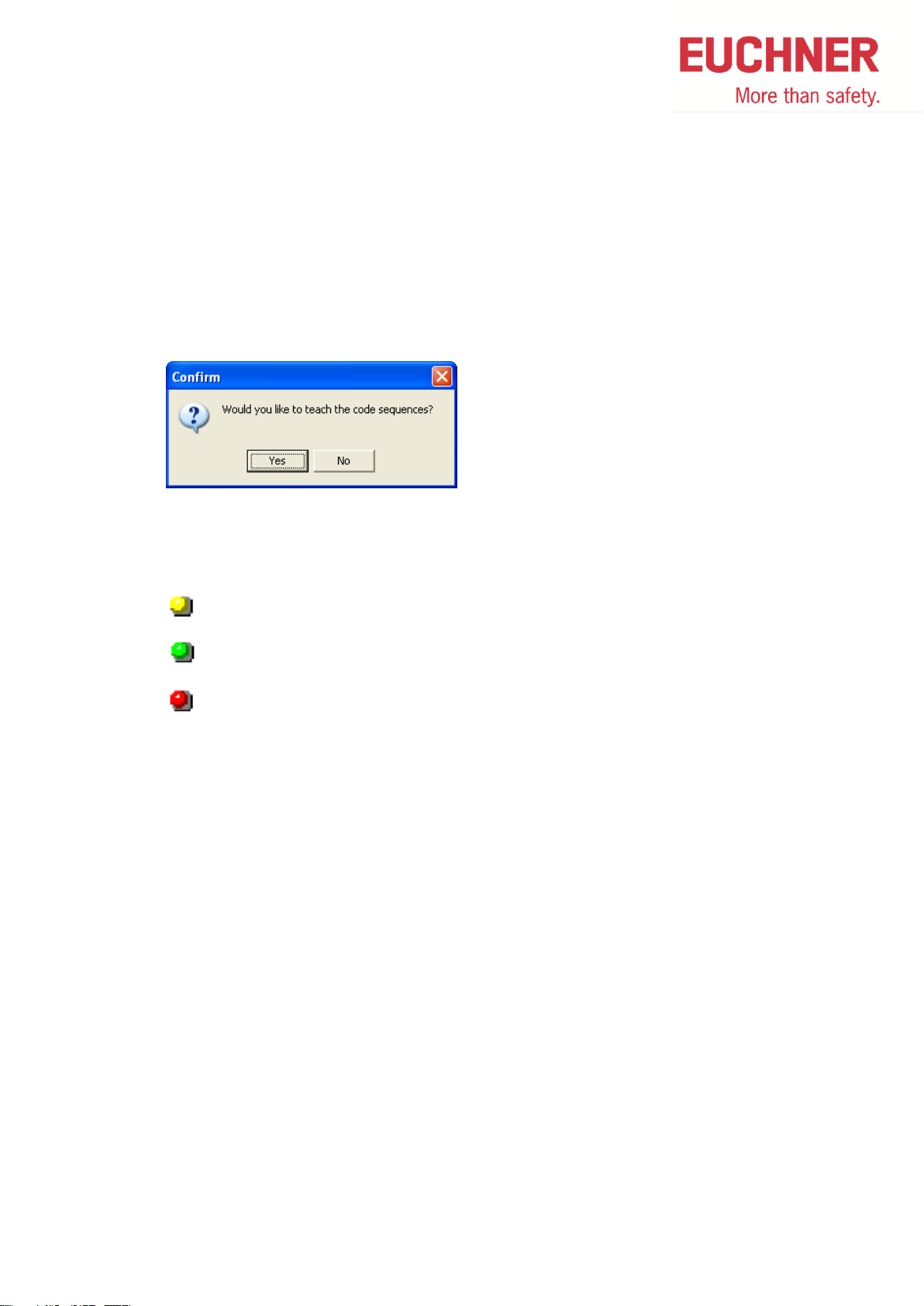
2.2 Delete Safety Monitor
A configured safety monitor can be deleted by the following method:
1. Stop safety monitor
2. Read configuration from safety monitor by menu MonitorMonitor -> PC…
3. Load this configuration by menu MonitorPC -> Monitor…
4. In the following picture click on no button
5. The safety monitor has a configuration, but is not verified and not learnt. He behaves
like an empty safety monitor.
Monitor is „empty“ when the 3 LEDs are alternately blinking
Safety Monitors - AS-i Quick Reference - 08/2014 7
Page 8
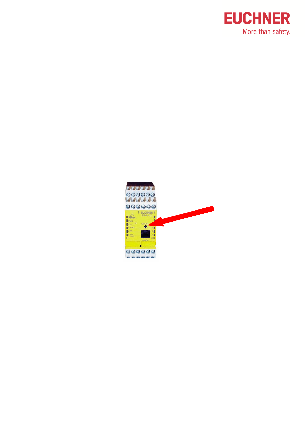
2.3 Replacing a defective Slave (without teach-in of actuator)
All safety slaves without necessity for teach-in of an actuator can be replaced without using a
PC with ASiMon according to this method.
1. Disconnect the defective slave from AS-Interface Bus
2. Press the service button on the monitor
– The monitor stores which slave address is missing
3. Connect new slave with address 0 AND bring it into a safe state
– The master addresses this slave automatically
4. Press the service button on the monitor
– The monitor has a check on the safety function of the new slave
Safety Monitors - AS-i Quick Reference - 08/2014 8
Page 9
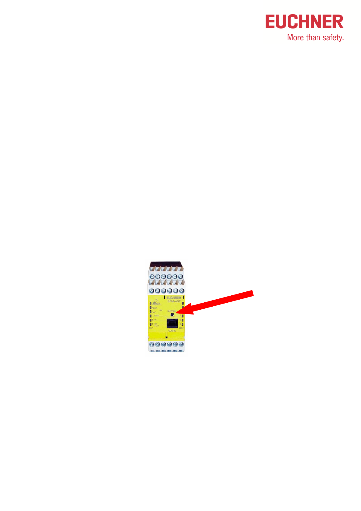
2.4 Replacing a defective Slave (with teach-in of actuator)
All safety slaves with necessity for teach-in of an actuator like CES and CET can be replaced
without using a PC with ASiMon according to this method.
1. Disconnect the defective slave from AS-Interface Bus
2. Connect new slave with address 0. Close locking if necessary.
– The master addresses this slave automatically
3. Teach-in of actuator according to operation manual
4. Dissconnect new slave from AS-Interface Bus
5. Press the service button on the monitor
– The monitor stores which slave address is missing
6. Connect new slave AND bring it into a safe state
7. Press the service button on the monitor
– The monitor has a check on the safety function of the new slave
Safety Monitors - AS-i Quick Reference - 08/2014 9
Page 10
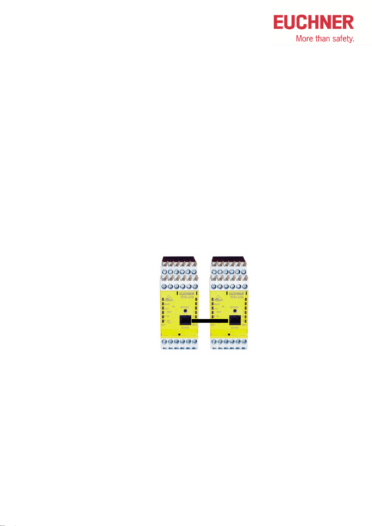
2.5 Replacing a defective Monitor
1. Separate the defective monitor completely
2. Connect new monitor but not power supply
3. Plug-in download cable to the new monitor
4. Connect the new monitor to power supply
– The monitor receives the data from the old monitor
– The yellow LED „Ready“ is permanently on during the data transmission
– The green LED is additionally permanently on when the data transmission is
completed
5. Disconnect the new monitor from power supply
6. Remove download cable and the old monitor, connect new monitor
7. Reconnect power to the new monitor
Safety Monitors - AS-i Quick Reference - 08/2014 10
Page 11
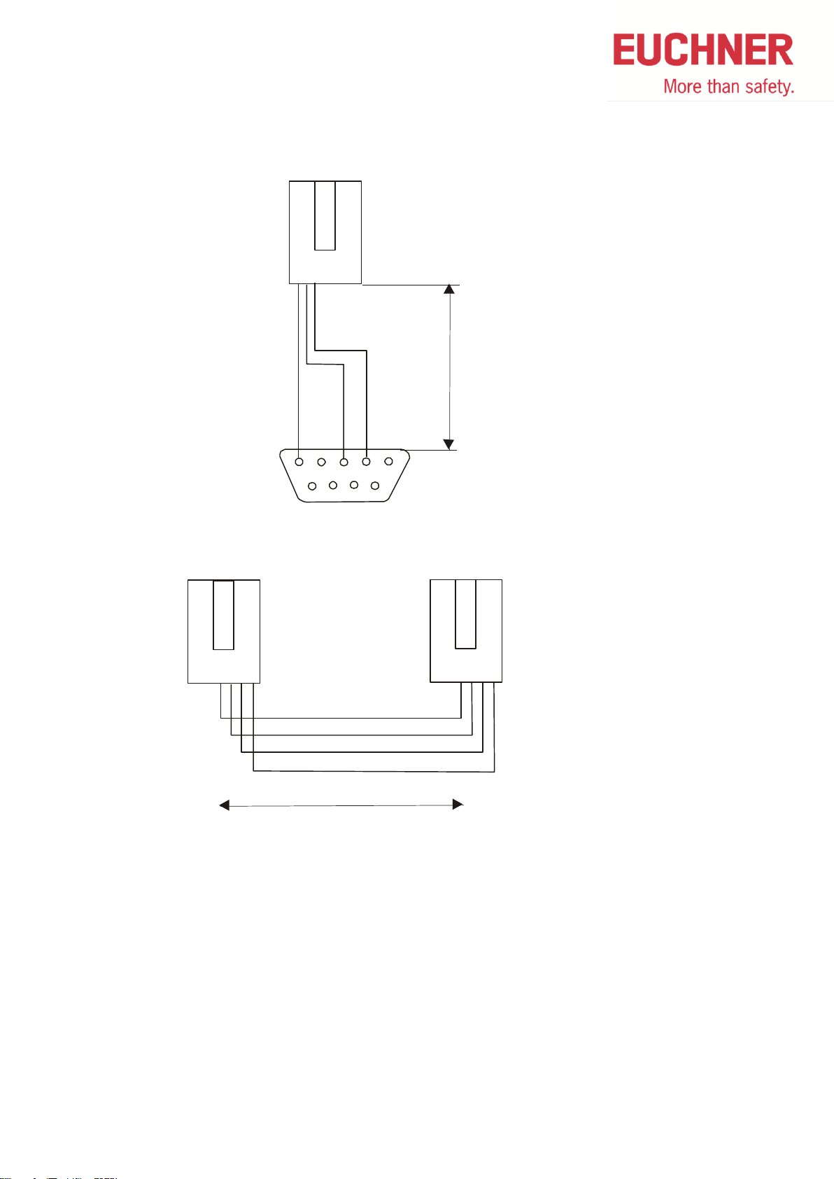
23
5
8
6
7
RJ45
Do not connect
the other pins!
Nur die angegebenen
Pins belegen!
M
a
x
.
2
.
5
m
4
RJ45
Do not connect
the other pins!
Nur die angegebenen
Pins belegen!
RJ45
3 2 1 4 3 2 1
Max. 0.1 m
2.6 Cable pin configuration for safety monitor
Safety Monitors - AS-i Quick Reference - 08/2014 11
Page 12

2.7 Faults shown at monitor and solution
Fault shown: Fault red blinking at monitor
Description: At exchange of a safe slave the monitor started blinking
Possible reason: The cable between monitor and PC is plugged in
Solution: Switch off monitor, plug off cable and repeat exchange of safe slave
Fault shown: Fault red blinking at monitor
Description: A safety door, which is configured as 2-channel dependant, was closed
Possible reason: The door does not stop totally in closed position
Solution: Use configuration 2-channel independent or 2-channele dependent with filtering
Fault shown: Ready is yellow blinking at monitor
Description: A safety door configured with 2-channel debounced is opened and immediately
closed again
Possible fault: The door was not open fort he full debouncing time
Solution: Door open again and let open minimum fort he debouncing time, then close again
Safety Monitors - AS-i Quick Reference - 08/2014 12
Page 13

LEDs Reason Action
Failure on AS-i
Monitor has no data
transfer to master
Check AS-i bus,
setup of master
SFM
Power
Fault
Ready
ON
OFF
Monitor waits for
new slave or is
empty
Push service button
or load monitor new
SFM
Power
Fault
Ready
ON
OFF
According LED on
According LED
blinking
LED off
Don’t care
Monitor waits for
new slave or is
empty
Push service button
or load monitor new
SFM
Power
Fault
Ready
ON
OFF
Resetable fault at
safe slave.
Fault is NOT in
monitor!
Quick help: power
off and on of
monitor.
Help:
Connect PG with
ASIMON and check
which address is in
state „yellow
blinking“.
SFM
Power
Fault
Ready
ON
OFF
Resetable fault at
safe slave.
Fault is NOT in
monitor!
Quick help: power
off and on of
monitor.
Help:
Connect PG with
ASIMON and check
which address is in
state „yellow
blinking“.
SFM
Power
Fault
Ready
ON
OFF
Non resetable fault
at safe slave.
Fault is NOT in
monitor!
Connect PG with
ASIMON and check
which address is in
state „red blinking“.
teach this slave new
or replace it.
SFM
Power
Fault
Ready
ON
OFF
Monitor defective Replace monitor
SFM
Power
Fault
Ready
ON
OFF
LEDs Ursache Maßnahme
Non resetable fault
at safe slave.
Fault is NOT in
monitor!
Connect PG with
ASIMON and check
which address is in
state „red blinking“.
teach this slave new
or replace it.
SFM
Power
Fault
Ready
ON
OFF
LED diagnostics at SFM monitors
Important:
With many of these failures there is no fault in the monitor. With
some failures a quick help is given by switching off and on the
monitor. For long term help the failure has to be detected.
Safety Monitors - AS-i Quick Reference - 08/2014 13
Page 14

3 GMOX Safety Monitor
3.1 Password forgotten or lost
If the password is lost for your configuration, proceed as follows:
Alternative 1
Find the valid configuration protocol for the AS-i Safety Monitor whose password is missing
(printout or file). In the configuration protocol in line 10 (Monitor Section, Validated) you will
find a 4-digit code.
Alternative 2
1. Connect the AS-i safety monitor whose password is missing to the PC and start the
ASIMON software.
2. Start the diagnostics function in ASIMON using MonitorDiagnostics and select a
neutral configuration. Wait until the current configuration appears on the screen. This
may take up to 1 minute.
3. Open the window EditInformation about monitor and bus. On the Title tab you
will find the 4-digit code in the Download time window area.
Safety Monitors - AS-i Quick Reference - 08/2014 14
Page 15

1 OFF 2 OFF
3 OFF 4 OFF
TEACH SAFETY
SAFE OUTPUT CH
SAFE COUPLING
START / STOP
CLEAR SAFE CFG
PIN
SAFE CHIPCARD
PROTECT
SAFE SUBST VAL
SAFE CHIPCARD
ACTIVE: BANK A
VIEW
CARD -> MONOTOR
…
SELECT BANK
A
OK
…
…
RELEASE CODE
C176
PROFIBUS
QUICK SETUP
AS-I SAFETY
DIAGNOSIS
SLAVE ADR TOOL
TEST
SETUP
DISP CONTRAST
Alternative 3 (it must be a memory card in the device)
1. Press OK-button
2. Select AS-I SAFETY and press OK-button
3. Select SAFE CHIPCARD and press OK-button
4. Select VIEW and press OK-button
5. Select OK and press OK-button
6. With the arrow-button completely down
Safety Monitors - AS-i Quick Reference - 08/2014 15
Page 16

If you have the 4- digit code …
1. Contact technical support at EUCHNER and enter the 4-digit code.
2. From this code a master password can be generated which can be used to access
the stored configuration.
3. Use this master password to stop the AS-i Safety Monitor and enter a new user
password. Select in the ASIMON software the menu MonitorPassword
changing...
Safety Monitors - AS-i Quick Reference - 08/2014 16
Page 17

1 OFF 2 OFF
3 OFF 4 OFF
TEACH SAFETY
SAFE OUTPUT CH
SAFE COUPLING
START / STOP
CLEAR SAFE CFG
PIN
SAFE CHIPCARD
PROTECT
SAFE SUBST VAL
CLEAR SAFE CFG
ENTER PIN
0000
OK
CLEAR SAFE CFG
CLEAR
PROFIBUS
QUICK SETUP
AS-I SAFETY
DIAGNOSIS
SLAVE ADR TOOL
TEST
SETUP
DISP CONTRAST
3.2 Delete Safety Monitor
1. Press OK-button
2. Select AS-I SAFETY and press OK-button
3. Select CLEAR SAFE CFG and press OK-button
4. Select OK and press OK-button
5. Select CLEAR and press OK-button
Safety Monitors - AS-i Quick Reference - 08/2014 17
Page 18

1 OFF 2 OFF
3 OFF 4 OFF
PROFIBUS
QUICK SETUP
AS-I SAFETY
DIAGNOSIS
SLAVE ADR TOOL
TEST
SETUP
DISP CONTRAST
SLAVE ADR TOOL
CONNECT NEW SLV
OLD ADDRESS
NEW ADDRESS
AS-I CIRCUIT 1
AS-I CIRCUIT 2
SLAVE ADR TOOL
OLD ADDRESS 5
NEW ADDRESS 17
PRG
3.3 Slave-Address-Tool in the Safety Monitor
This function enables setting and changing the addresses of both new and already
configured AS-i slaves.
1. Press OK-button
2. Select SLAVE ADR TOOL and press OK-button
3. Select AS-I circuit in which is the Slave and press OK-button
4. Select CONNECT NEW SLV and press OK-button
5. Edit old and new address by OK-button
6. Select PRG and press OK-button
Safety Monitors - AS-i Quick Reference - 08/2014 18
Page 19

SLAVE 6 TO
BE CONNECTED
THEN PRESS
SERVICE LONG
3.4 Replacing a defective slave (without teach-in of actuator)
If an AS-i safety slave is defective, it can be replaced even without a PC or reconfiguration of
the AS-i Safety Monitor by pressing the ESC/Service key on the AS-i Safety Monitor.
All safety slaves without necessity for teach-in of an actuator can be replaced without using a
PC with ASiMon according to this method.
Proceed as follows:
1. Disconnect defective slave from AS-i bus.
2. Press the ESC/Service button on the AS-i Safety Monitor approx. 3 seconds.
3. Connect new slave with address 0 AND bring into safe state
The monitor addresses this slave automatically
4. Press the ESC/Service button on the AS-i Safety Monitor approx. 3 seconds.
The code table for the new slave is taught and checked for correctness. If this is OK,
the AS-i Safety Monitor changes to protecting mode.
Safety Monitors - AS-i Quick Reference - 08/2014 19
Page 20

SLAVE 6 TO
BE CONNECTED
THEN PRESS
SERVICE LONG
3.5 Replacing a defective slave (with teach-in of actuator)
If an AS-i safety slave is defective, it can be replaced even without a PC or reconfiguration of
the AS-i Safety Monitor by pressing the ESC/Service key on the AS-i Safety Monitor.
All safety slaves with necessity for teach-in of an actuator like CES and CET can be replaced
without using a PC with ASiMon according to this method.
Proceed as follows:
1. Disconnect defective slave from AS-i bus.
2. Connect new slave with address 0
The monitor addresses this slave automatically
3. Teach-in of actuator according to operation manual
4. Dissconnect new slave from AS-Interface Bus
5. Press the ESC/Service button on the AS-i Safety Monitor approx. 3 seconds.
6. Connect new slave AND bring into safe state
7. Press the ESC/Service button on the AS-i Safety Monitor approx. 3 seconds.
The code table for the new slave is taught and checked for correctness. If this is OK,
the AS-i Safety Monitor changes to protecting mode.
Safety Monitors - AS-i Quick Reference - 08/2014 20
Page 21

CODES LERNEN
PIN EINGEBE
0000
OK
TEACH CODES
COMPLETE
SINGLE SLAVE
COUPLING SLAVE
SNGL SLAVE_CODE
TEACH SAFETY
SAFE OUTPUT CH
SAFE COUPLING
START / STOP
CLEAR SAFE CFG
PIN
SAFE CHIPCARD
PROTECT
SAFE SUBST VAL
1 OFF 2 OFF
3 OFF 4 OFF
PROFIBUS
QUICK SETUP
AS-I SAFETY
DIAGNOSIS
SLAVE ADR TOOL
TEST
SETUP
DISP CONTRAST
3.6 Reset Safety Error (caused by exchange of a safety slave)
When exchanging safety slaves, especially within combined machines a safety error can
occur, when the method according to 4.4 “Replacing a defective slave” was not used. When
one GMOx did not learn the new safety code, this fault occurs. This device can learn the new
code also without repeating the full procedure.
1. Press OK-button
2. Select AS-I SAFETY and press OK-button
Safety Monitors - AS-i Quick Reference - 08/2014 21
3. Select TEACH SAFETY and press OK-button
4. Select SINGLE SLAVE and press OK-button
5. Enter PIN, when used and select OK and press OK-button
6. Select AS-I circuit fort he slave to teach and press OK-button
Page 22

AS-I CIRCUIT 1
AS-I CIRCUIT 2
TEACHING CODES
SLAVE ADDR 1
ESC OK
ATTENTION: The monitor now switches all outputs off
7. Key in SLAVE ADDR of the slave to teach, select OK and press OK-button
Safety Monitors - AS-i Quick Reference - 08/2014 22
Page 23

Command
Description
CHIPCARD > MASTER
Chip card data are copied to the master
MASTER -> CHIPCARD
Master data are copied to the chip card
CONTINUING
No change to the data
1 OFF 2 OFF
3 OFF 4 OFF
CHIPCARD AND
AS-I DATA
DIFFERENT
CHIPCARD -> MASTER
MASTER -> CHIPCARD
CONTINUING
PROFIBUS
QUICK SETUP
AS-I SAFETY
DIAGNOSIS
SLAVE ADR TOOL
TEST
SETUP
DISP CONTRAST
3.7 Replacing a defective AS-i Safety Monitor
If an AS-i Safety Monitor is defective and needs to be replaced, the replacement unit does
not necessarily have to be newly configured using the ASIMON software, and rather it is
possible to copy the configuration of the defective device using a chip card.
If the card and device are not empty at start and the data are not identical, an error message
is displayed and the card is not synchronized with the device. The following menu is then
automatically opened:
To choose the menu manually:
1. Press OK-button
2. Select AS-I SAFETY and press OK-button
Safety Monitors - AS-i Quick Reference - 08/2014 23
Page 24

TEACH SAFETY
SAFE OUTPUT CH
SAFE COUPLING
START / STOP
CLEAR SAFE CFG
PIN
SAFE CHIPCARD
PROTECT
SAFE SUBST VAL
SAFE CHIPCARD
ACTIVE: BANK A
VIEW
CARD -> MONITOR
MONITOR -> CARD
CLEAR CODES
CLEAR SAFE CARD
CARD -> MONITOR
ENTER PIN
0000
OK
SELECT BANK
A
OK
COPY BANK A TO
MONITOR
COMPLETE
CONFIGURATION
…
…
…
…
…
RELEASE CODE
B275
------------------------------RELEASE CODE?
0000 OK
3. Select SLAVE ADR TOOL and press OK-button
4. Select CARD -> MONITOR and press OK-button
5. Select OK and press OK-button
6. Select A, B, C ,D and press OK-button
7. With the arrow-button completely down
8. Enter the Code (B275) and press OK-button
Safety Monitors - AS-i Quick Reference - 08/2014 24
Page 25

1 OFF 2 OFF
3 OFF 4 OFF
PROFIBUS
QUICK SETUP
AS-I SAFETY
DIAGNOSIS
SLAVE ADR TOOL
TEST
SETUP
DISP CONTRAST
WARNIG:
OUTPUTS MAY BE
SET AND HOST MAY
LOOSE CONTROL.
AS-I CIRCUIT 1
AS-I CIRCUIT 2
BINARY OUTPUTS
D3…D0
1A - 0 0 0 0
2A - 0 0 0 0
…
SLAVE TEST TOOL
BINARY INPUTS
BINARY OUTPUTS
ANALOG INPUTS
ANALOG OUTPUTS
PARAMETERS
3.8 Set outputs of the slaves
With this function the outputs of the slaves can be tested.
1. Press OK-button
2. Select TEST and press OK-button
3. Select AS-I circuit in which is the Slave and press OK-button
4. Press OK-button
5. Select BINARY OUTPUTS and press OK-button
6. Select desired Slave by arrow buttons and press OK-button.
7. Set output by arrow buttons and press OK-button to go to the next output
Safety Monitors - AS-i Quick Reference - 08/2014 25
Page 26

1 OFF 2 OFF
3 OFF 4 OFF
PROFIBUS
QUICK SETUP
AS-I SAFETY
DIAGNOSIS
SLAVE ADR TOOL
TEST
SETUP
DISP CONTRAST
SAFETY SLAVES
INT MONITOR
EXT MONITOR
FAULT DETECTOR
…
SAFETY ORIENTED
SLAVES
1- 2-XX
3-RR 4-XX
5-ON 6…
AS-I CIRCUIT 1
AS-I CIRCUIT 2
3.9 Diagnostics of slaves in Safety Monitor
1. Press OK-button
2. Select DIAGNOSIS and press OK-button
3. Select SAFETY SLAVES and press OK-button
4. Select AS-I circuit in which is the Slave and press OK-button
5. With the arrow-buttons up and down
X => channel is OK
R => channel has released
ON => output on
OFF => output off
? => output state unknown
Safety Monitors - AS-i Quick Reference - 08/2014 26
Page 27

Sub Min D 9
PS/2 Connector
2
1
3
2
5
3 and 5
7
4
2
1 2
3
5
4
6
7
5
3.10 Cable pin configuration for GMOX
Pinning:
View PS/2 connector at GMOx:
Safety Monitors - AS-i Quick Reference - 08/2014 27
Page 28

Fatal Error
Comment
Help
154 159 007 002
Fault at
semiconductor output
Check the connections to the device. Check 24V,
probably shortcut or overload at semiconductor at output
4. The maximum load for semiconductor outputs is
500mA.
154 159 007 130
Fault at
semiconductor output
Check the connections to the device. Check 24V,
probably shortcut or overload at semiconductor at output
4. The maximum load for semiconductor outputs is
500mA.
154 159 015 002
Fault at
semiconductor output
The safety CPU cannot switch off output 4 for testing
purposes for less than 1ms.Reasons may capacities or
supplying 24V.
154 159 015 130
Fault at
semiconductor output
The safety CPU cannot switch off output 4 for testing
purposes for less than 1ms.Reasons may capacities or
supplying 24V.
154 159 025 001
Internal device fault
Send back device to manufacturer
154 159 081 004
Relay fault
Send back device to manufacturer
154 159 096 002
Relay fault
Send back device to manufacturer
154 159 103 004
Internal device fault
Send back device to manufacturer
154 159 105 130
Relay fault
Send back device to manufacturer
154 159 128 003
Relay fault
Send back device to manufacturer
154 159 137 002
Relay fault
Send back device to manufacturer
154 159 174 002
Fault at
semiconductor output
Check the connections to the device.
154 159 190 001
Fault at
semiconductor output
Check the connections to the device. Check 24V,
shortcut or overload possible.
154 159 196 002
Fault at
semiconductor output
The safety CPU cannot switch off output 3 for testing
purposes for less than 1ms.Reasons may capacities or
supplying 24V.
154 159 198 001
Fault at
semiconductor output
or supply voltage
Check the connections to the device.
Check 24V, shortcut or overload at semiconductor
output or breakdown of 24V power supply possible.
154 159 198 129
Fault at
semiconductor output
Check safe output connections.
154 159 221 002
Fault at
semiconductor output
Check safe output connections.
154 159 240 001
Fault at
semiconductor output
or supply voltage
Check the connections to the device.
Check 24V, shortcut or overload at semiconductor
output or breakdown of 24V power supply possible.
154 159 246 003
Internal device fault
Send back device to manufacturer
159 175 116 129
Internal device fault
Send back device to manufacturer
159 175 245 128
Internal device fault
Send back device to manufacturer
188 214 093 004
Internal device fault
Send back device to manufacturer
3.11 Fatal Errors
List of „Fatal Errors“ in SMOx und GMOx devices
Safety Monitors - AS-i Quick Reference - 08/2014 28
Page 29

1 OFF 2 OFF
3 OFF 4 OFF
PROFIBUS
QUICK SETUP
AS-I SAFETY
DIAGNOSIS
SLAVE ADR TOOL
TEST
SETUP
DISPLAY CONTRAST
Hint to „Fault at semiconductor output “
There are several possible reasons for getting this fault:
When the output is having an internal overload.
When the adjacent 24 V DC at pin “24 V” is missing and the output is switched ON
Wiring fault at electronic output (e.g.: 0V off electronic outputs is missing at the monitor
device).
The failure is often laying in the external wiring Please check especially whether the 24 V
DC are connected permanently (NOT switched) at pin “24 V”.
Typically the device works after Power on Reset.
Fault codes, not contained in this list
The list of fault codes is not complete. If there is another fault code shown in the display
please contact EUCHNER in order to get the description.
Additionally to the fatal error code please prepare the Identno or the name of the device and
the version number (on a side sticker of the device)
Very helpful is to know about the internal software version. The version is to be found in the
menu of the device. For getting the versions please follow the instructions below:
1. Press OK-button
Safety Monitors - AS-i Quick Reference - 08/2014 29
2. Select DIAGNOSIS and press OK–button
Page 30

Display
LCD
AS-i-Slave-Addresses, Fault messages
LED power
Power ON
LED PROFIBUS
PROFIBUS-Master detected
LED config error
Configuration wrong
LED U AS-i
AS-i-Power OK
LED AS-i active
AS-i-operation normal
LED prg enable
Automatic slave addressing possible
LED prj mode
Project mode active
LED AUX
Auxiliary power connected
4 x LED EDM/Start
State of inputs of external feedback loop monitoring
LED off: circuit open
LED on: circuit closed
4 x LED output circuits
State of output circuits
LED off: circuit open
LED on: circuit closed
AS-I CIRCUIT 1
AS-I CIRCUIT 2
SAFETY SLAVE
INT MONITOR
EXT MONITOR
FAULT DETECTOR
DELTA LIST
LCS
ERROR COUNTERS
LPF
FLAGS
ACTUAL CONFIG
AS-I MASTER
3. Select AS-I MASTER and press OK-button
4. Select AS-i CIRCUIT 1 and press OK-button
5. Read Software IDs
For analysing the fault, please write down „SWID“, „Safe CPU-A“, „Safe CPU-B“,
„UART 1“, „UART 2“.
3.12 States of GMOX Safety Monitor
Safety Monitors - AS-i Quick Reference - 08/2014 30
Page 31

Display
Colour
Meaning
green,
continuous
Device is in the ON state (switched on)
green,
flashing
Device is in the ON state (switched on), but already in the process
of being switched to the OFF state, e.g. switch-off delay
yellow,
continuous
Device is ready, but still waiting for another condition, e.g. local
acknowledgement, diagnosis stop or start button
yellow,
flashing
A (start) test must be performed, bring slave into OFF state and
then into ON state
red,
continuous
Device is in the OFF state (switched off)
rot,
flashing
The error lock is active, release by means of one of the following
actions:
Reset of error condition with the Service button
Power OFF/ON
AS-Interface bus OFF/ON
grey,
off
No communication with the AS-interface slave
4 Software ASiMon
4.1 Diagnostics with Software ASiMon
circuit diagram display
With Strg + T and Strg + S can be switched between circuit diagram display and tree
structure display
Tree structure display
Safety Monitors - AS-i Quick Reference - 08/2014 31
Page 32

GP, NZ, NX, SGP
Programming: dual channel dependent
State
Monitor diagnostics
Door closed
green
With local acknowledgment: yellow blinking at
startup
Intermittent state at closing or opening of
door: channel 1 (internally) open
At opening: yellow blinking
At closing: red
After rundown of synchronization time: yellow
blinking
Intermittent state at closing or opening of
door: channel 2 (internally) open
Door open
red
Address 0 or no communication
grey
TP..AS2
Programming: dual channel dependent
State
Monitor diagnostics
Door closed, lock open or closed
green
Intermittent state at closing or opening of
door: channel 1 (internally) open
At opening: yellow blinking
At closing: red
After rundown of synchronization time: yellow
blinking
Intermittent state at closing or opening of
door: channel 2 (internally) open
Door open
red
Address 0 or no communication
grey
4.2 State of AS-i Safety Switches
Safety Monitors - AS-i Quick Reference - 08/2014 32
Page 33

CET, TP, STP, STA, TZ, BI, all AS1
Programming: dual channel conditionally
dependent
State
Monitor diagnostics
Door closed and locked
green
Door closed and lock open
yellow blinking
Invalid state (Door open, Lock closed)
red blinking (monitoring of invalid state)
Door open
red
Address 0 or no communication
grey
CET, TP, STP, STA, TZ, BI, alle AS1
Programming: dual channel independent
State
Monitor diagnostics
Door closed and locked
green
Door closed and lock open
red
Invalid state (Door open, Lock closed)
red (no monitoring of invalid state)
Door open
red
Address 0 or no communication
grey
CET, TP, STP, STA, TZ, BI, alle AS1
Programming: dual channel dependent,
Synchronization time ∞
State
Monitor diagnostics
Door closed and locked
green, when door was open before or after startup
yellow blinking, when only lock was open
Door closed and lock open
yellow blinking, when door was close before
red, when door was open before
Invalid state (Door open, Lock closed)
yellow blinking, when door was close before
red, when door was open before
Door open
red
Address 0 or no communication
grey
Safety Monitors - AS-i Quick Reference - 08/2014 33
Page 34

CES
Programming: dual channel dependent,
Synchronization time 0,5s
State
Monitor diagnostics
Door closed
green
Door open, transponder half detected
yellow blinking
(Please refer to the operation manual for further
help)
Door open
red
Address 0 or no communication
grey
Safety Monitors - AS-i Quick Reference - 08/2014 34
 Loading...