

Page 1
SMART™ Chamber
(Statistical Mode Averaging Reverberation Test Site)
Installation, Operation,
& Maintenance Manual
Page 2

ETS-Lindgren L.P. reserves the right to make changes to any product described
herein in order to improve function, design, or for any other reason. Nothing
contained herein shall constitute ETS-Lindgren L.P. assuming any liability
whatsoever arising out of the application or use of any product or circuit
described herein. ETS-Lindgren L.P. does not convey any license under its
patent rights or the rights of others.
© Copyright 2004–2009 by ETS-Lindgren L.P. All Rights Reserved. No part
of this document may be copied by any means without written permission
from ETS-Lindgren L.P.
Trademarks used in this document: The ETS-Lindgren logo and SMART are
trademarks of ETS-Lindgren L.P; Scotch-Brite is a registered trademark for 3M.
Revision Record | MANUAL,SMART CHAMBER | Part #399275, Rev. E
Revision Description Date
A Initial Release March, 2004
B Updates/edits August, 2005
C Updated tuner Installation
Procedure; rebrand
D Added EC Declaration of
Conformity
E Updated Warranty July, 2009
ii |
July, 2008
November, 2008
Page 3

Table of Contents
Notes, Cautions, and Warnings ................................................ v
ETS-Lindgren Product Information Bulletin ............................ v
1.0 Good Shielding Practices ................................................... 7
2.0 Maintenance ......................................................................... 9
Optional Maintenance Program ..................................................................... 9
Tuners .......................................................................................................... 10
Cleaning ............................................................................................... 11
Doors ........................................................................................................... 11
Monthly Maintenance ........................................................................... 12
Annual Maintenance ............................................................................ 13
Replacing Finger Stock and Vinyl Seal ............................................... 13
Finger Stock Repair ............................................................................. 14
Service Procedures ..................................................................................... 15
3.0 Tuners ................................................................................. 17
General Precautions .................................................................................... 17
Installation Procedure for SMART 200 and Larger Chambers .................... 18
Electrical .............................................................................................. 25
Vertical Tuner Installation .................................................................... 25
Tuner Control – SMART 1000 ..................................................................... 25
RS-232 Port Settings ........................................................................... 26
Operation ............................................................................................. 26
Command Syntax ................................................................................ 27
Tuner Control – SMART 80 and SMART 200 .............................................. 27
4.0 Shielding ............................................................................. 29
Series 81 Modular Shielding ........................................................................ 29
Pan-Type Shielding ..................................................................................... 30
5.0 Power Line Filters .............................................................. 31
6.0 Vents ................................................................................... 33
7.0 Penetrations ....................................................................... 35
8.0 Doors ................................................................................... 37
General Precautions .................................................................................... 37
| iii
Page 4

Door Types .................................................................................................. 38
Door Operation for Types A, B, C, D, E, and F ............................................ 38
Type A Door Latch ............................................................................... 39
Type B Door Latch ............................................................................... 39
Door Operation for Type G .......................................................................... 40
Adjusting RCM 1 Hinges .............................................................................. 40
Up-and-Down Adjustment.................................................................... 40
Side-to-Side Adjustment ...................................................................... 40
Appendix A: Warranty ............................................................. 43
Appendix B: EC Declaration of Conformity .......................... 45
iv |
Page 5
Notes, Cautions, and Warnings
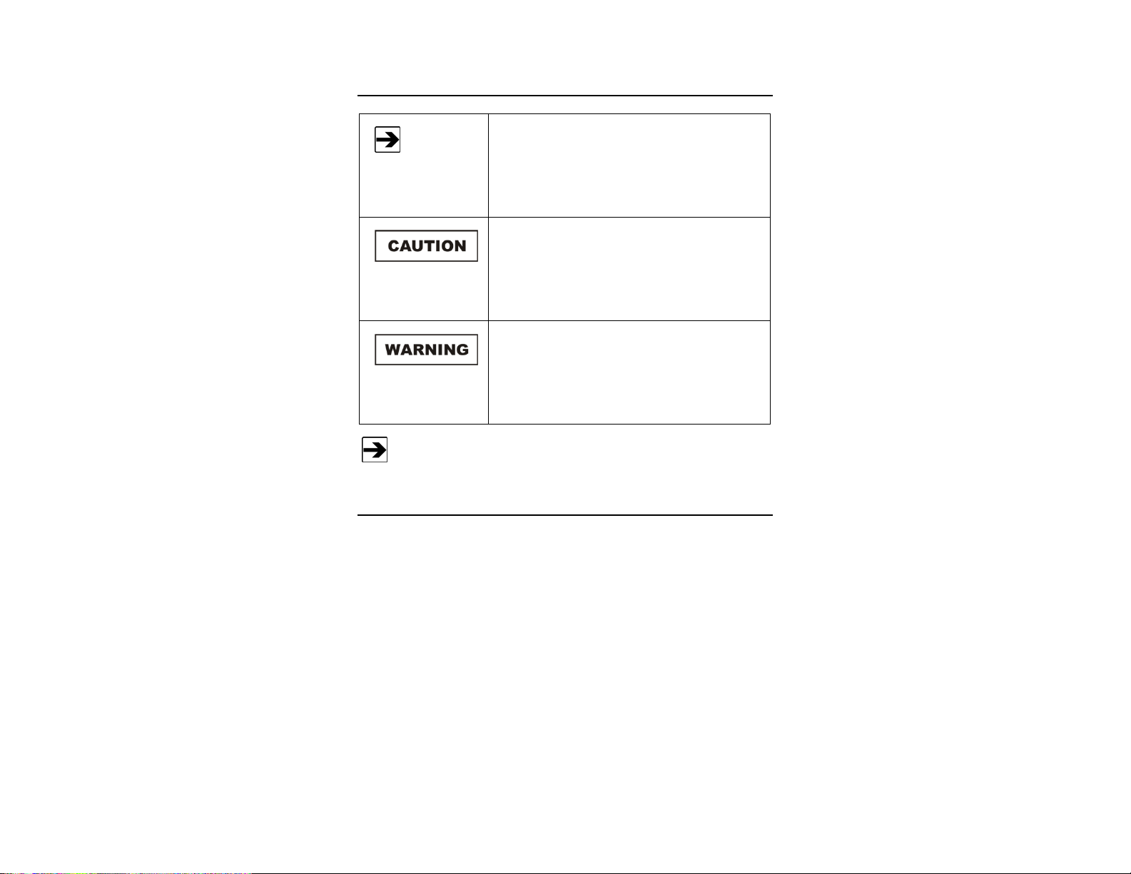
Note: Denotes helpful information intended to
See the ETS-Lindgren Product Information Bulletin for safety,
regulatory, and other product marking information.
provide tips for better use of the product.
Caution: Denotes a hazard. Failure to follow
instructions could result in minor personal injury
and/or property damage. Included text gives proper
procedures.
Warning: Denotes a hazard. Failure to follow
instructions could result in SEVERE personal injury
and/or property damage. Included text gives proper
procedures.
ETS-Lindgren Product Information Bulletin
See the ETS-Lindgren Product Information Bulletin included with your shipment
for the following:
• Warranty information
• Safety, regulatory, and other product marking information
• Steps to receive your shipment
• Steps to return a component for service
• ETS-Lindgren calibration service
• ETS-Lindgren contact information
| v
Page 6

This page intentionally left blank.
vi |
Page 7

1.0 Good Shielding Practices
To retain the RF shielding integrity of the chamber, follow these good shielding
practices:
• Periodically clean and lubricate doors.
• When mounting screw-retaining items within the enclosure, do not
penetrate through both shields of a modular panel system. Screws
must not penetrate any portion of the screen system.
• Do not use framing screws to fasten items within the enclosure.
• When a hole is bored for a new penetration, remove all burrs. Clean
the perimeter of the hole and the penetration with a cleaning agent
before installing the new penetration.
• Nothing must penetrate the enclosure wall, floor, or ceiling without use
of a proper ETS-Lindgren designated penetration.
• Bolts fitted to the modular and pan-type rooms must be fitted to
correctly-sized holes, correctly de-burred, and cleaned.
• Use flat washers on both sides of the shield penetration.
Good Shielding Practices | 7
Page 8

This page intentionally left blank.
8 | Good Shielding Practices
Page 9

2.0 Maintenance
Before performing any maintenance, follow the
safety information in the ETS-Lindgren
Product Information Bulletin included with your
shipment.
If you have any questions concerning maintenance, contact ETS-Lindgren
Customer Service.
Optional Maintenance Program
ETS-Lindgren offers an optional maintenance program that consists of a
complete package of services for continued RF integrity in the shielded
enclosures. The services may be performed on a three-month or six-month cycle.
The program consists of the following:
• Inspection of doors and access panels. Extreme care will be taken
to repair, clean, and lubricate the RF seals (fingers and vinyl seals). If
necessary, they will be replaced.
• Inspection of hinges. Hinges will be checked for alignment and
adjusted as needed.
• Inspection of door and access panel latching mechanisms.
Latching mechanism of doors and access panels will be inspected.
Any defective or worn components which cannot be repaired will be
replaced. Adjustment will be performed as needed. Extra material used
to replace damaged parts due to abuse or failure to comply with
recommended maintenance procedures will be charged to the
customer.
• Inspection of tuners. Tuner operation will be checked, lubricated, and
adjusted as necessary.
Maintenance | 9
Page 10

Tuners
The SMART™ (Statistical Mode Averaging Reverberation Test Site) chamber
tuners are manufactured from rigid structure of gatorboard covered with copper
sheet on the Z-fold section to provide the necessary reflective surface, or of an
aluminum frame with aluminum reinforced sheet reflectors.
No maintenance of the box structure is required in normal use. However, the
surfaces may be dusted or vacuumed periodically to maintain their appearance.
The tuners are supported at their ends only with coupling clamps. These should
be inspected monthly for signs of wear, loose screws, or distortion.
The motors mounted external to the chamber are fixed to the chamber
wall and additionally supported either on a separate frame or the
chamber supports. The motor shaft passes into the chamber through
a shielded penetration fitted to the chamber wall. The horizontal
penetration also ensures that the axial load is not transmitted to the
motor from the tuner.
The RF feed through bearing assembly on the motor side and a self-aligning (on
large chambers) idler bearing on the non-driven end supports the horizontal
tuner. The self-aligning bearing assemblies have a grease nipple that should be
topped off every six months using standard bearing grease. They should also be
checked periodically to ensure free movement and that fixings remain secure.
The tuner body needs only periodic cleaning to remove any accumulated dust.
On all chambers the RF feed-through assembly on the motor side of the tuner
contains a large number of ball bearings. These provide the RF shielding of the
gear shaft as it passes through the shield and should not be removed.
On the SMART 1000 model the tuners are much smaller and subject to less
wear. The tuners should be inspected every six months for signs of excessive
noise or motor overheating. The tuners are lubricated at the factory, so additional
lubrication should not be required.
10 | Maintenance
Page 11

CLEANING
Removal of the tuner assembly must be
performed by qualified ETS-Lindgren
personnel.
• Remove excess dust from the tuner and bearing assembly with a dry
cloth or vacuum.
• Check the fixings to the shielded room and the tuner assemblies.
Doors
Periodically clean the brass or steel door frame and beryllium copper finger stock
with Channel Master® 9101 lubricant. See the decal applied to the door for more
detailed instructions. If staining or corrosion is present on the brass frame or
finger stock, polish lightly with 3M Scotch-Brite® pads. If extreme staining or
corrosion persists, call ETS-Lindgren for assistance.
Periodically inspect the roller cams and cam blocks to verify that a thin film of
lubricant is present. If additional lubricant is required, apply a very thin film of
silicone grease. The door maintenance kit included with each door contains the
necessary lubricants, cleaning material, and replacement finger stock.
Maintenance | 11
Page 12

Do not polish the brass or beryllium copper
finger stock with steel wool, electric sanders,
wire brushes, medium or fine sandpaper, or any
abrasive materials or devices other than those
specified in Maintenance on page 40.
Do not polish any of the brass striking surfaces
with any type of brass polish.
Do not apply a floor wax to the door sill of door
types D and E (flush sills). Use caution when
waxing the floors inside and outside the
enclosure to make sure that wax is not applied
to the flush door saddle.
Do not apply wax to the metal surfaces of the
chamber.
Do not attempt to oil hinges or door handles.
They are permanently lubricated.
MONTHLY MAINTENANCE
To catch excess fluids, place absorbent material (cloth, sponge, and so on)
beneath the entire length of the door sill prior to cleaning and lubricating. Do not
wipe finger stock.
Perform proper cleaning and lubrication of the contact finger
mechanism every month.
Use the cleaning agent Channel Master 9101; lubricate only in accordance with
the manufacturer instructions.
1. Use a generous amount of the cleaning agent to flush the entire finger
recess on the door frame. Start across the top of the door frame and
work down both sides. Flush bottom last. This process will wash off all
visible residues on fingers.
2. Wipe brass door frame with a clean cloth.
12 | Maintenance
Page 13

3. Inspect finger stock; install new finger stock where necessary.
4. Wipe knob edge on door leaf with a clean cloth wetted with cleaning
agent.
ANNUAL MAINTENANCE
1. Perform maintenance as described in Monthly Maintenance (see
previous section).
2. During inspection of finger stock, count the number of patches that
have been replaced. If more than five patches have been replaced,
remove all finger stock (part# 81D-6L) and vinyl seal shield
(part# VS-100) from the channel. Install new finger stock and new seal.
3. Lubricate tuner bearing grease nipples using standard bearing grease.
4. Check motor supply and signal cable condition external to the
chamber.
5. Remove excess dust from motor (and amplifier, if fitted).
REPLACING FINGER STOCK AND VINYL SEAL
1. Remove old finger stock and vinyl seal using needle-nose pliers.
2. Clean channel.
Use the cleaning agent as described in the manufacturer instructions.
3. Cut exact lengths of finger stock for each of the four sides of the frame.
4. Cut exact length of vinyl seal.
5. Starting in upper left corner, install first row of finger stock down the
entire side of the frame.
6. Lubricate fingers and channel again.
7. Again starting in the upper left corner, insert second row of finger stock
down the entire side of the frame. Fingers should be gently pressed
into position one at a time until they are locked in place.
8. Repeat steps 5, 6, and 7 for each of the remaining three sides of the
frame.
Maintenance | 13
Page 14
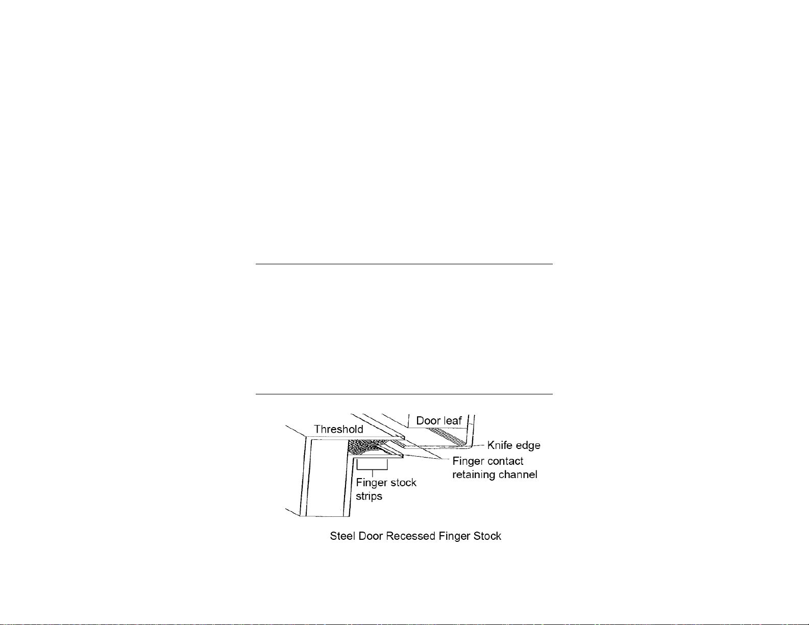
9. Re-lubricate all finger stock and channel.
10. Beginning in the middle of the side of the frame, start installing the
vinyl seal by inserting it by hand into the channel opening. Go around
the door frame so that the vinyl seal covers the finger stock completely.
11. Using the right angle corner of a rectangular piece of sheet metal
(about 4 in x 8 in x 16 ga.) or a wide putty knife, gently push the vinyl
seal between the two rows of finger stock to the final position at the
base of the channel. Use caution at the corners to insert the vinyl seal
behind one finger at a time.
12. If fingers are broken during insertion of the vinyl seal, a patch section
must be inserted.
FINGER STOCK REPAIR
For All Doors
You can replace recessed finger stock without removing the door.
Finger stock 81D-6L can be replaced in sections if a maximum of 10 inches is
damaged.
1. Remove broken or loose pieces with needle-nose pliers.
2. Select an overlapping piece not less than four inches longer than the
missing section and insert new finger stock.
For Door Type D and Type E
14 | Maintenance
Page 15

1. Follow the finger stock repair instructions in For All Doors (see
previous section) for door types D and E.
The flush sill requires the following additional instructions.
2. Type D door—Remove all screws at the bottom edge of the type D
door that permit removal of the finger stock angle.
Finger stock is soldered onto this removable brass angle at the bottom
of the door. As with replacement of recessed fingers, it is not
necessary to remove the door to replace the finger stock at the sill.
Use a sharp instrument (such as a penknife) to remove the section of
broken fingers.
Install new finger stock 81D-6L by overlapping one finger at each end
of old finger stock; solder the perforated area of a new finger to the
brass plate.
Make sure that the solder does not flow to the fingers; this anneals the
temper of the fingers and will cause them to break during use.
3. Type E door—The type E double flat sill door uses a different finger
support arrangement. The 16-in finger strips are retained by an
aluminum strip that must be removed to access the fingers. A
removable steel strip retains the fingers on the center carrier.
Additional parts are included in the Steel Door Maintenance Kit,
part# UM144.
Service Procedures
For the steps to return a system or system component to ETS-Lindgren for
service, see the Product Information Bulletin included with your shipment.
Maintenance | 15
Page 16

This page intentionally left blank.
16 | Maintenance
Page 17

3.0 Tuners
General Precautions
Do not stand beneath the horizontal tuner or in
the path of the vertical tuner while they are
under remote control or moving. It is
recommended that a warning indication or
barrier be placed in the chamber to reduce the
risk of damage or injury during operation.
Do not use abrasives on the tuner assembly.
Clean only with vacuum or by dusting.
The tuners must never be turned manually by
pushing the tuners (except SMART 1000
tuners). This could result in damage to the
support shaft or motor/gear box assembly.
Do not fit any additional loads to the tuner
assemblies. The motor acceleration and
deceleration profiles have been set to account
for the inertia of the tuners; changing the loads
could overstress the couplings or gear box
assembly. Manually running the tuners at
speeds in excess of the preset limits could also
result in damage and should not be performed.
Do not cover any surface of the tuners. This
could affect the performance of the chamber.
For the SMART 1000 tuners, the zero or home
position is indicated with a mark in the
chamber; see the following illustration.
See Maintenance on page 9 for information on recommended tuner
maintenance and cleaning.
Tuners | 17
Page 18

Zero/home position
Installation Procedure for SMART 200 and
Larger Chambers
Before installing any components, follow the
safety information in the ETS-Lindgren
Product Information Bulletin included with your
shipment.
Tuner installation steps are provided for both the S81 sandwich-type and
pan-type shields. The installation is similar with differences in the mounting
bracket assembly. The tuners may be installed during or after the completion of
the chamber installation. Access will be required on both the inner and outer
sides of the wall panels for the installation of the horizontal tuner.
Review the entire installation procedure before beginning.
18 | Tuners
Page 19

1. Determine the orientation of the motor, and then place the motor on a
clear surface to check plug locations. Locate the oil plug behind the
mounting flange. Locate the vent and drain plugs and verify that they
are positioned so that the vent and filler plugs are uppermost on the
gear box with the drain at the lowest position. If necessary, move to
another position on the gear box.
2. Mark the location on the chamber wall where the tuner motor is to be
mounted. Using the mounting plates as a template, mark the motor
and fixing holes in the shield.
Tuners | 19
Page 20

3. Verify that the idler mounting plate can be mounted at the opposite end
without obstruction, and that the motor(s) can be mounted in horizontal
or vertical orientation without obstruction, and with suitable fixing.
4. Cut the holes in the panel as required for the shaft and the
four mounting screws.
20 | Tuners
Page 21

5. Mount the motor and fix securely to the chamber wall with the outer
plate, inner plate, and bearing cup.
• Using an axial laser level, locate and mark the position for the tuner
idler bearing on the opposite wall. This must be directly aligned with
the motor shaft.
Tuners | 21
Page 22

• Mount bearing inner and outer plate.
• Using a lift, raise the tuner into position and align the shaft ends. Fix
the couplers without the key to the motor shaft end and bearing end if
a separate shaft is used. Alternatively, insert the tuner end shaft into
the idler bearing and secure with the fixing (set/grub) screws.
• For the vertical tuner, locate the tuner shaft in the ceiling clamp to
temporarily support the weight of the tuner.
• Locate and fix the idler bearing to the floor using wood screws supplied
for modular panels (S81) or bolts to the inner floor of the pan-type
room.
• Secure the tuner shaft in the idler bearing with at lease 1/2-in (12-mm)
gap between the shaft and chamber surface. Secure the set screw so
that tuner weight can be taken by the bearing.
• Release the motor coupling and insert the key into the keyway. Tighten
coupling.
22 | Tuners
Page 23

• Fill the bearing housing with the supplied shot.
Tuners | 23
Page 24

• Remove grease cap next to shot filler hole and fill with the conductive
grease supplied, then replace. Do not overfill to the point where
excessive grease is visible on the shaft.
• Mount the motor control panel in a convenient position on the outer
wall of the chamber, within easy reach for operation of the emergency
stop.
• Route and secure cables and fibers as necessary to the motor
controller and power supply.
• Check installation before powering on. Confirm that the bearing
housing cap is secure and check all fixings.
• Rotate tuner using the controller and verify free operation.
6. For the pan-type chamber, mark the location of the motor angle
bracket. Fix the motor to the bracket and the bracket to the chamber
support so that the motor plate is perpendicular to the shield wall. The
motor should be supported by the chamber support structure.
24 | Tuners
Page 25

ELECTRICAL
The tuner motor is connected to the control unit at the factory and supplied with a
length of conduit appropriate to the chamber. The control unit should be mounted
on the wall of the chamber within easy reach to operate the emergency switch.
Each tuner motor is a three-phase unit with a variable speed drive control. Each
motor uses less than eight amps under normal load.
The unit should be connected to a protected 208–230 volt, 15A supply, with the
wires connected as follows:
Brown: Phase 1
Blue: Phase 2
Green / Yellow: Earth
For chambers with two tuners, the motor controllers can be connected to a single
20-amp supply.
VERTICAL TUNER INSTALLATION
1. Install the motor end of the tuner as described in the installation
procedures beginning on page 18.
2. Using on the inner mounting plate, mount the idler bearing as
described in the installation procedures beginning on page 18.
3. Fix the plate to the inner shield surface using adhesive or wood screws
penetrating only the inner surface of the panel.
Tuner Control – SMART 1000
The SMART™ (Statistical Mode Averaging Reverberation Test Site)
1000 chambers are fitted with a dedicated motor drive control unit mounted onto
the back of the chamber. This unit controls the motors for both the vertical and
horizontal tuners. The motors are linked to 10:1 gear box and use half-stepping,
providing 400 steps per revolution. The motor controller is set so that the
required angular position of the motor is defined by θ/4.5, which means that the
angular position used in the seek command must be divided by 4.5.
Tuners | 25
Page 26

The current position (CP) read from the controller returns the corrected value.
The tuners can be operated in either a stepped (tuned) mode with step size from
two-degree increments, or a stirred mode with one of three available speed
settings using the Sx command. The stepper motors can provide position
feedback while switched on and when queried will reply with the current tuner
position relative to the zero position set at switch on.
Stored tuner positions do not exist; therefore, the tuners default to a setting of
zero degrees when powered on, regardless of actual position. The home position
for the tuners should always be set prior to performing measurements using the
indications provided on the inside of the chamber. This also represents the
home position used for the factory calibration.
Communication is through an RS-232 interface. Two ports are required for the
two tuners. Following are the required computer settings.
RS-232 PORT SETTINGS
Baud Rate: 9600
Bits: 8
Parity: None
Stop Bit: One
Flow Control: None
OPERATION
The antennas fitted to the SMART 1000 can be used for either transmit or
receive depending if the chamber is being used for immunity or emission
measurements. In either case, calibration data can be used to provide
corrections for the measured quantities.
SMART 1000 chambers are provided either with two antennas covering the
entire frequency range of 1 to 40 GHz or with two identical antennas from
1 to 18 GHz (one transmit and one receive). The chamber is calibrated at the
factory and supplied with the chamber calibration factors based on the
IEC61000-4-21 method.
26 | Tuners
Page 27

COMMAND SYNTAX
Use a program that allows direct communication with the COM ports to verify
satisfactory operation of the tuners; for example, ETS-Lindgren SMARTImm
Immunity Control Software.
Command Parameters Function Example
Sx 0/1/2/3/ ? Set tuner speed/Query S1
CR NA Continuous rotation
NCR NA Non-continuous rotation
ST NA Stop
CPnnn.n 000.0-999.9/ ? Current Position/Query CP180.0
CC NA Move CCW
CW NA Move CW
ULnnn.n 000.0 – 999.9 / ? Set CW Limit/Query UL360.0
LLnnn.n 000.0 – 999.9 / ? Set CCW Limit/Query LL000.0
DIR? NA Query Direction
SKnn.n* nn.n – 80* Seek Position SK75
* Angle required divided by 4.5; for example, 300/4.5 = 75
Tuner Control – SMART 80 and SMART 200
The SMART 80, SMART 200, and other large chambers are operated using the
ETS-Lindgren Model 2090 Multi-Device Controller (or next generation
ETS-Lindgren controller, if applicable). The command set for the controller is
described in detail in the controller manual. Go to www.ets-lindgren.com
download the controller manual.
Operation of all SMART chambers is described in detail in the SMARTImm
Immunity Control Software and SMARTEmi Emission Control Software manuals.
These programs are used to control the chamber and contain the necessary
drivers for all available tuner control options.
Tuners | 27
to
Page 28

This page intentionally left blank.
28 | Tuners
Page 29

4.0 Shielding
Series 81 Modular Shielding
DESCRIPTION: Two layers of sheet steel laminated to a wood core.
OPERATION:
The RF shield must be installed by or the
installation supervised by a qualified individual.
TYPE: Modular Systems—Series 81 (28 ga. steel)
Modular panels joined with 11 ga. ETS-Lindgren
framing system using 1/4 in screws on 4-in centers.
After the enclosure is installed, the interior finishes should not be
changed. It is important that:
1. Liquids are not spilled on the shielding.
2. Only ETS-Lindgren RF penetration be used through the walls,
floors, and ceiling.
3. Framing screws are not used to secure any item to the wall.
4. All screws are tightened to 90-in lb torque. If screws are
removed, they must be reinstalled with the use of a calibrated
torque wrench or screw gun.
Shielding | 29
Page 30

Pan-Type Shielding
TYPE: Pan-Type Systems—Euroshield (18 ga. steel or
aluminum)
DESCRIPTION: One layer of sheet steel or aluminum, joined with
M8 screws and double-row gasket in all mating joints.
OPERATION:
After the enclosure has been installed, the interior finishes should
not be changed. It is important that:
1. Liquids are not spilled on the shielding.
2. Only ETS-Lindgren RF penetration be used through the
walls, floors, and ceiling.
3. All screws are tightened to 90-in lb torque. If screws are
removed, they must be reinstalled with the use of a
calibrated torque wrench or screw gun.
4. Suspended floors are earthed with bonded contact to the
shield walls. Changing this bonding could affect the
chamber performance.
30 | Shielding
Page 31

5.0 Power Line Filters
An electrician generally installs power line filters at the time of the enclosure
installation. After the filters are put into service, they rarely require maintenance.
Should a problem occur, only a qualified electrician should troubleshoot the
problem.
Most power line filters have a built-in voltage
discharge system. However, it is possible for
the discharge system to be inoperative in
certain conditions; therefore, all filters must be
discharged prior to being handled. To
discharge filters a resistance greater than
100,000 ohms must be used in the discharge
probe.
Power Line Filters | 31
Page 32

This page intentionally left blank.
32 | Power Line Filters
Page 33

6.0 Vents
Honeycomb vents are used for the ventilation system of the enclosure and
normally do not require maintenance. The honeycomb vents work as a
waveguide beyond cut-off and are sized depending on the upper frequency of
operation of the chamber. High frequency rooms, therefore, use small bore
vents. Conductors of any kind must not be passed through the vents or the
performance of the vent will be drastically reduced.
Should the accumulation of lint or dust require that the honeycomb be cleaned,
the duct system on both sides of the honeycomb must be opened so that the
honeycomb vent may be vacuum-cleaned from both sides. The duct system
should then be reinstalled per the original construction.
Vents | 33
Page 34

This page intentionally left blank.
34 | Vents
Page 35

7.0 Penetrations
Penetrations must be provided for any services which pass through the walls,
floor, or ceiling of the enclosure. These penetrations are normally put in place at
the time the enclosure is installed and rarely require maintenance.
Exceptions are for active penetrations such as cable feed-throughs,
tuner penetrations, and coaxial fittings, which must be re-tightened occasionally.
Installation of a new penetration can be performed by the customer but must be
done in accordance with ETS-Lindgren shielding practices. For more information,
see Good Shielding Practices on page 7.
Penetrations | 35
Page 36

This page intentionally left blank.
36 | Penetrations
Page 37

8.0 Doors
ETS-Lindgren manufactures RF shielding doors. Doors are one of the most
active and, therefore, the most vulnerable components of any reverb chamber.
The instructions in this section must be followed to retain the RF integrity of the
enclosure.
General Precautions
Do not slam the door to start engaging the
fingers. This is not necessary with the
ETS-Lindgren latching mechanism and could
result in damage to the latch roller assembly.
Do not shove or kick the door when opening.
The contact finger pressure release is
performed entirely by the ETS-Lindgren
latching mechanism.
Do not attempt to close the door with the
handle rotated in the full stop or closed
position. This may break off the latching roller
pins.
Do not exert excess pressure on the door
handle. A nominal force of 25 lb is all that is
required until full stop or full open positions are
reached. Excessive forces could result in
broken latch pins.
If the closing or opening forces become
excessive, the door should be serviced.
See Maintenance on page 9 for information on recommended door
maintenance, including steps to replace and repair finger stock.
Doors | 37
Page 38

Door Types
• Type A—RCM Light Weight
• Type B—RCM Single
• Type C—RCM Double
• Type D—RCM Flush Sill, Single
• Type E—RCM Flush Sill, Double
• Type F—RCM Access Panel
• Type G—Sliding Doors, Manual and Automatic
Door Operation for Types A, B, C, D, E, and F
In the operation of the door, the ETS-Lindgren cam-actuated latching mechanism
brings the door to a completely closed condition with the handle rotated to the full
stop position. Conversely, when the handle is rotated in the opposite direction to
the alternate position, the door knife edge is removed from the finger contacts,
allowing the door to fully open. In this position the door will swing freely with little
opposition.
When closing the door, normal door pressure should be applied until the
cam actuators are engaged in the cam blocks. At this point no further inward
pressure on the door is required. Rotate the door handle until the handle has
reached the full stop position. The cam action of the door latching mechanism
provides all the pressure required to separate and correctly contact the fingers.
On large double-leaf swing doors, the surface area of the contact fingers is larger
so the latching effort required is slightly greater. At no time should more than
hand pressure be required or applied to the latch mechanism.
Flush sill doors have a double or triple row of contact fingers fitted to the bottom
edge. These are exposed and should be checked periodically for damage.
38 | Doors
Page 39

TYPE A DOOR LATCH
TYPE B DOOR LATCH
Doors | 39
Page 40

Door Operation for Type G
This door is most often installed on large chambers for large equipment access.
Operating and maintenance instructions differ quite significantly from the
standard swing doors; therefore, individual operation and maintenance manuals
are issued with each door fitted to a chamber.
Adjusting RCM 1 Hinges
Adjustment is the same for left and right hinges. All hinges must be aligned
together.
UP-AND-DOWN ADJUSTMENT
1. Open the door.
2. Place a hex key in the top of the hinge pin.
3. Turn the hinge pin clockwise to move the door leaf up; turn the hinge
pin counterclockwise to move the door down. Approximately three to
four turns are typically required to set the correct spacing between
door and the jamb; for example, 1/8 in (3 mm) to 5/32 in (4 mm).
4. Close the door.
5. Repeat as required.
SIDE-TO-SIDE ADJUSTMENT
1. Adjust each hinge as required to move either the top or bottom of the
door leaf.
2. Close the door. Do not loosen the dome head nuts on the frame side of
the hinge.
3. Loosen the M5 x 10 mm grub screw on the side of the hinge fitted to
the door leaf.
4. Loosen the three dome nuts on the hinge (3/8-in diameter).
5. Move the door leaf to set the correct spacing between door and the
jamb. Tighten dome nuts and torque to 12 ft lb.
40 | Doors
Page 41

6. Insert and tighten the grub screw until it touches the middle bolt of the
hinge to stop the door from moving.
7. Open and close the door. Check the spacing at the door and jam.
Adjust as required.
8. Tighten all bolts to correct torque setting.
Doors | 41
Page 42

This page intentionally left blank.
42 | Doors
Page 43

Appendix A: Warranty
See the Product Information Bulletin included with your shipment for
the complete ETS-Lindgren warranty.
DURATION OF WARRANTIES
All product warranties, except the warranty of title, and all remedies for warranty
failures are limited to the warranty period indicated in the following table.
Product Warranted Duration of Warranty Period
Anechoic Chamber Performance 5 Years
Antennas 2 Years
Positioning Equipment 2 Years
Field Probes 3 Years
Doors & Accessories 1 Year
Filters 1 Year
Telescoping Sprinkler Assemblies 1 Year
Custom Equipment 1 Year
Cables & Connectors 1 Year
CCTV 2 Years
Warranty | 43
Page 44

This page intentionally left blank.
44 | Warranty
Page 45

Appendix B: EC Declaration of Conformity
EC Declaration of Conformity | 45
 Loading...