


 Loading...
Model HI-6113
Laser Data Interface
and Probe Measurement System
User Manual
ETS-Lindgren Inc. reserves the right to make changes to any product described herein in order to improve function, design, or for any other reason. Nothing contained herein shall constitute ETS-Lindgren Inc. assuming any liability whatsoever arising out of the application or use of any product or circuit described herein. ETS-Lindgren Inc. does not convey any license under its patent rights or the rights of others.
© Copyright 2005–2012 by ETS-Lindgren Inc. All Rights Reserved. No part of this document may be copied by any means without written permission from ETS-Lindgren Inc.
Trademarks used in this document: The ETS-Lindgren logo and ProbeView are trademarks of ETS-Lindgren Inc.; Microsoft, Windows, and Windows Vista are registered trademarks of Microsoft Corporation in the United States and/or other countries; Intel and Pentium are registered trademarks of Intel Corporation.
ii |
Revision Record | MANUAL, HI-6113 | Part #H-600098, Rev. H
|
|
|
Revision |
Description |
Date |
|
|
|
A |
Initial Release |
June, 2005 |
|
|
|
B |
Edits to all sections for updated |
October, 2006 |
|
HI-6113 design; Field Probe content |
|
|
moved to EMC Field Probes User |
|
|
Manual; reorganized content, updated |
|
|
format |
|
|
|
|
C |
Added Appendix B: EC Declaration of |
December, 2006 |
|
Conformity; Updated descriptions of I |
|
|
and r commands in Appendix A: |
|
|
Operating Protocols |
|
|
|
|
D |
Updated ProbeView™ Laser |
November, 2007 |
|
information |
|
|
|
|
E |
Updated download information; |
September, 2008 |
|
rebrand |
|
|
|
|
F |
Added Notes, Cautions, and |
March, 2011 |
|
Warnings; added General Safety |
|
|
Considerations |
|
|
|
|
G |
Updated USB driver installation |
October, 2011 |
|
information |
|
|
|
|
H |
Updated LASER HOT description in |
November, 2012 |
|
HI-6113 Indicators. |
|
|
|
|
| iii
Table of Contents |
|
Notes, Cautions, and Warnings.............................................. |
vii |
General Safety Considerations ............................................. |
viii |
1.0 Introduction .......................................................................... |
9 |
System Description..................................................................................... |
9 |
Minimum Computer Requirements............................................................ |
10 |
ETS-Lindgren Product Information Bulletin ............................................... |
11 |
2.0 Maintenance ....................................................................... |
13 |
Laser Probes and Maintenance of Fiber Optics......................................... |
13 |
Replacement and Optional Parts .............................................................. |
14 |
Service Procedures .................................................................................. |
15 |
3.0 Quick Start to Operation ................................................... |
17 |
Download and Install the Software ............................................................ |
17 |
Connect the Hardware .............................................................................. |
17 |
Run a Warm Up Period............................................................................. |
18 |
Run the System ........................................................................................ |
19 |
Field Probe Operating Protocols ............................................................... |
19 |
4.0 HI-6113 Indicators .............................................................. |
21 |
5.0 ProbeView Laser Software................................................ |
23 |
Download and Install ProbeView Laser..................................................... |
23 |
Start ProbeView Laser .............................................................................. |
24 |
ProbeView Laser Main Screen.................................................................. |
25 |
ProbeView Laser Menus ........................................................................... |
25 |
File Menu.......................................................................................... |
26 |
View Menu ........................................................................................ |
27 |
Probe Menu ...................................................................................... |
29 |
Communications Menu ..................................................................... |
31 |
Help Menu ........................................................................................ |
32 |
Probe Interaction Screen .......................................................................... |
32 |
Communication Status.............................................................................. |
33 |
Field Intensity.................................................................................... |
33 |
Units ................................................................................................. |
34 |
iv |
Temperature ..................................................................................... |
34 |
Probe Information ............................................................................. |
34 |
Peak ................................................................................................. |
34 |
Bar Graph ......................................................................................... |
34 |
Using Excel with ProbeView Laser............................................................ |
35 |
Options Window........................................................................................ |
35 |
Moving Average ................................................................................ |
36 |
Text update rate................................................................................ |
36 |
Annotating Logged Data ................................................................... |
36 |
Colors ............................................................................................... |
37 |
Human Exposure ...................................................................................... |
38 |
Miscellaneous ........................................................................................... |
38 |
Sample Limit ..................................................................................... |
38 |
Auto Update Interval ......................................................................... |
38 |
Sample Rate ..................................................................................... |
39 |
Zoom-In / Zoom-Out ......................................................................... |
39 |
Human Exposure (Health and Safety) ............................................... |
39 |
Appendix A: Warranty ............................................................. |
41 |
Appendix B: Operating Protocols .......................................... |
43 |
Communication Protocol ........................................................................... |
43 |
Information Transfer Protocol.................................................................... |
43 |
Command Structure.......................................................................... |
43 |
Commands ....................................................................................... |
44 |
HI-6113 Laser Data Interface Commands ......................................... |
46 |
Error Codes .............................................................................................. |
47 |
Appendix C: EC Declaration of Conformity .......................... |
49 |
| v
This page intentionally left blank.
vi |

Notes, Cautions, and Warnings
Note: Denotes helpful information intended to provide tips for better use of the product.
Caution: Denotes a hazard. Failure to follow instructions could result in minor personal injury and/or property damage. Included text gives proper procedures.
Warning: Denotes a hazard. Failure to follow instructions could result in SEVERE personal injury and/or property damage. Included text gives proper procedures.
See the ETS-Lindgren Product Information Bulletin for safety, regulatory, and other product marking information.
| vii

General Safety Considerations
LASER HAZARD. Laser power up to 150 mW at
830 nm may be accessible at the fiber connector of the laser. However, the laser beam itself is not hazardous as the interlock ensures that the exposure time will be less than 30 ms.
See the ETS-Lindgren Product Information Bulletin for safety, regulatory, and other product marking information.
viii |
1.0 Introduction
System Description
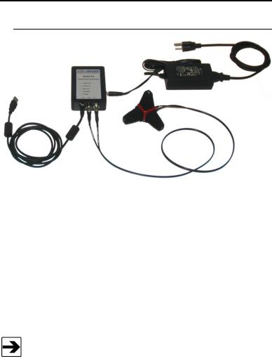
The ETS-Lindgren HI-6113 Laser Data Interface and Field Probe Measurement System consists of:
HI-61XX Series Field Probe
HI-6113 Laser Data Interface
Universal input DC power supply
Fiber optic cables
ProbeView Laser software download—To download ProbeView Laser, see page 23
See Minimum Computer Requirements on page 10 for the computer specifications required to install and operate the HI-6113.
The HI-61XX Series Field Probe contains a photo-voltaic converter that provides power to the probe circuitry when sufficient light power is received by the converter. The light power is generated by a laser in the HI-6113, and is transmitted to the converter through an optical fiber cable assembly. This duplex fiber cable is also used for communication between the Field Probe and the HI-6113.
Introduction |
| |
9 |

The HI-6113 is an automated laser controller that accepts commands from the software running on the computer and then returns the requested data. Upon receiving the command to turn on the system, the HI-6113 initiates a startup sequence that turns on the laser, which provides power to the Field Probe. The Field Probe, when powered up and running, continuously sends data to the HI-6113. The HI-6113 returns data to the computer software upon request in either unprocessed raw form or processed form, depending on the requested data format. The USB interface provides the data communication between the computer software and the HI-6113.
The Field Probe system incorporates a safety interlock mechanism that turns off the laser if the HI-6113 does not receive data from the probe within a specified time frame. The safety mechanism is intended to prevent injury from the laser if the HI-6113 issues a command to turn on the laser while the fiber optic cables are disconnected, improperly connected, cut, or damaged.
The universal input power supply provides 5 volts DC power to the HI-6113.
Minimum Computer Requirements
To install ProbeView Laser and operate the Field Probe and HI-6113, you must have an Intel® Pentium® III computer with one USB port, installed with one of the Microsoft® Windows® operating systems; see page 18 for a list of supported operating systems. An externally powered USB hub may be required for computers without a USB port.
Due to the graphics in ProbeView Laser, a 300 MHz processor or better is desirable. A slower machine will run ProbeView Laser, but the sample rates will be slower. Toggling off the bar and scatter graphs may increase sample rate performance.
10 |
| |
Introduction |
Sample Setup (computer not included)
ETS-Lindgren Product Information Bulletin
See the ETS-Lindgren Product Information Bulletin included with your shipment for the following:
Warranty information
Safety, regulatory, and other product marking information
Steps to receive your shipment
Steps to return a component for service
ETS-Lindgren calibration service
ETS-Lindgren contact information
Introduction |
| |
11 |
This page intentionally left blank.
12 |
| |
Introduction |

2.0 Maintenance
WARRANTY |
Before performing any maintenance, follow the safety information in the ETS-Lindgren Product Information Bulletin included with your shipment.
Maintenance of the HI-6113 is limited to external components such as cables or connectors.
If you have any questions concerning maintenance, contact ETS-Lindgren Customer Service.
Laser Probes and Maintenance of Fiber Optics
The fiber optic connectors and cables used with laser-powered probes can be damaged from airborne particles, humidity and moisture, oils from the human body, and debris from the connectors they plug into. Always handle connectors and cables with care, using the following guidelines.
Maintenance |
| |
13 |

Before performing any maintenance, disconnect the fiber optic cables from the unit and turn off power.
When disconnecting fiber optic cables, apply the included dust caps to the ends to maintain their integrity.
Before connecting fiber optic cables, clean the connector tips and in-line connectors.
Before attaching in-line connectors, clean them with moisture-free compressed air.
Failure to perform these tasks may result in damage to the fiber optic connectors or cables.
Replacement and Optional Parts
Following are the part numbers for ordering replacement or optional parts for the HI-61XX Series Field Probe.
|
|
|
|
|
|
Part Description |
|
|
Part Number |
|
|
|
|
|
|
Laser Data Interface Probe Kit |
|
|
H-600098 |
|
Manual |
|
|
|
|
|
|
|
|
|
Cable Assembly, Fiber, FC-FC, |
|
|
H-491263-xx |
|
ST-ST |
|
|
(xx = length in meters) |
|
|
|
|
|
|
|
|
|
|
|
ST to ST Inline Connector |
|
708027 |
|
|
|
|
|
|
|
FC to FC Inline Connector |
|
|
H-23861521000 |
|
|
|
|
|
|
Tripod, Dielectric, Field Probe |
|
|
H-491009 |
|
|
|
|
|
|
Probe Stand |
|
|
H-491269 |
|
|
|
|
|
14 |
| |
Maintenance |
||

Service Procedures
For the steps to return a system or system component to ETS-Lindgren for service, see the Product Information Bulletin included with your shipment.
Maintenance |
| |
15 |
Loading...