


 Loading...
EMC Field Probes
User Manual
ETS-Lindgren L.P. reserves the right to make changes to any product described herein in order to improve function, design, or for any other reason. Nothing contained herein shall constitute ETS-Lindgren L.P. assuming any liability whatsoever arising out of the application or use of any product or circuit described herein. ETS-Lindgren L.P. does not convey any license under its patent rights or the rights of others.
© Copyright 2006–2013 by ETS-Lindgren L.P. All Rights Reserved. No part of this document may be copied by any means without written permission from ETS-Lindgren L.P.
Trademarks used in this document: The ETS-Lindgren logo, ProbeView, LaserPro, and ProbeView II are trademarks of ETS-Lindgren L.P; Microsoft and Windows are registered trademarks of Microsoft Corporation in the United States and/or other countries.
ii |

Revision Record
MANUAL,EMC PROBES | Part #H-600100, Rev. K
Revision |
Description |
Date |
A |
Initial Release |
December, 2006 |
|
|
|
B |
Added EC Declaration of Conformity; updated |
January, 2007 |
|
descriptions of I and r commands in Operating |
|
|
Protocols; consistency/quality edits |
|
|
|
|
C |
Added FM5004 Field Monitor to Introduction; |
April, 2007 |
|
added new sections, Typical Configurations |
|
|
and HI-6153 Electric Field Probe; updated |
|
|
photos, specifications, battery replacement in |
|
|
HI-6053 Field Probe; added HI-6153 to Probe |
|
|
Stand; updated service procedures, safety |
|
|
notices |
|
|
|
|
D |
Updated H-491269 Probe Stand |
November, 2007 |
|
|
|
E |
Added information for HI-6022 and HI-6122 |
March, 2008 |
|
probes |
|
|
|
|
F |
Updated HI-6153 fiber optic connectors; |
May, 2008 |
|
branding updates |
|
|
|
|
G |
Added HI-4413USB content |
October, 2009 |
|
|
|
|
Added ETSProbe DLL User Guide |
|
|
|
|
H |
Removed HI-4422 content; removed |
October, 2010 |
|
FM5004 content |
|
|
|
|
I |
Added General Safety Considerations |
March, 2011 |
|
|
|
J |
Updated About Probe Operation |
June, 2011 |
|
|
|
|iii

Revision |
Description |
Date |
|
K |
|
Updated Specifications: All probes |
February, 2013 |
|
|
||
|
Added Typical Isotropic Response charts: |
|
|
|
|
HI-6105, HI-6005, HI-6153, HI-6053 |
|
|
Updated Frequency Response charts: |
|
|
|
|
All probes |
|
|
Updated Additional Parts: All probes |
|
|
|
Added laser shutoff information to |
|
|
|
|
Laser-Powered Field Probes |
|
|
|
|
|
iv |
Table of Contents
Notes, Cautions, and Warnings............................................... |
ix |
General Safety Considerations ................................................ |
x |
ETS-Lindgren Product Information Bulletin............................ |
x |
1.0 Introduction ........................................................................ |
11 |
Readout Options....................................................................................... |
12 |
HI-6100 Field Monitor ....................................................................... |
12 |
HI-6113 Laser Data Interface............................................................ |
12 |
HI-4413P Fiber Optic Modem............................................................ |
13 |
HI-4413USB Fiber Optic to USB Converter ....................................... |
13 |
Optional Tripod ......................................................................................... |
14 |
Optional Probe Stand................................................................................ |
15 |
About Probe Operation ............................................................................. |
16 |
2.0 Typical Configurations...................................................... |
17 |
HI-6100 Field Monitor Configuration.......................................................... |
18 |
HI-6113 Laser Data Interface Configuration .............................................. |
19 |
HI-4413P / HI-4413USB Configuration...................................................... |
20 |
3.0 Maintenance ....................................................................... |
21 |
Annual Calibration .................................................................................... |
21 |
Laser Probes and Maintenance of Fiber Optics......................................... |
22 |
Upgrade Policies....................................................................................... |
22 |
Service Procedures .................................................................................. |
22 |
4.0 Laser-Powered Field Probes ............................................ |
23 |
HI-6122 Electric Field Probe ..................................................................... |
24 |
HI-6122 Specifications ...................................................................... |
24 |
HI-6122 Operation ............................................................................ |
25 |
HI-6122 Typical Frequency Response .............................................. |
26 |
HI-6122 Typical Isotropic Response.................................................. |
27 |
HI-6122 Additional Maintenance ....................................................... |
28 |
HI-6122 Additional Parts ................................................................... |
28 |
HI-6153 Electric Field Probe ..................................................................... |
30 |
HI-6153 Specifications ...................................................................... |
30 |
HI-6153 Operation ............................................................................ |
32 |
HI-6153 Typical Frequency Response .............................................. |
33 |
| |
v |
HI-6153 Typical Isotropic Response.................................................. |
34 |
HI-6153 Additional Maintenance ....................................................... |
37 |
HI-6153 Additional Parts ................................................................... |
37 |
HI-6105 Electric Field Probe ..................................................................... |
39 |
HI-6105 Specifications ...................................................................... |
39 |
HI-6105 Operation ............................................................................ |
40 |
HI-6105 Typical Frequency Response .............................................. |
41 |
HI-6105 Typical Isotropic Response.................................................. |
42 |
HI-6105 Additional Maintenance ....................................................... |
43 |
HI-6105 Additional Parts ................................................................... |
43 |
5.0 Battery-Operated Field Probes......................................... |
45 |
HI-6022 Field Probe.................................................................................. |
46 |
HI-6022 Specifications ...................................................................... |
46 |
HI-6022 Operation ............................................................................ |
47 |
HI-6022 Power Switch ...................................................................... |
48 |
HI-6022 Typical Frequency Response .............................................. |
49 |
HI-6022 Typical Isotropic Response.................................................. |
50 |
HI-6022 Additional Maintenance ....................................................... |
51 |
HI-6022 Additional Parts ................................................................... |
51 |
HI-6053 Field Probe.................................................................................. |
53 |
HI-6053 Specifications ...................................................................... |
53 |
HI-6053 Operation ............................................................................ |
55 |
HI-6053 Power Switch ...................................................................... |
56 |
HI-6053 Controls............................................................................... |
57 |
HI-6053 Typical Frequency Response .............................................. |
58 |
HI-6053 Typical Isotropic Response.................................................. |
59 |
HI-6053 Additional Maintenance ....................................................... |
62 |
HI-6053 Battery Replacement ........................................................... |
62 |
HI-6053 Additional Parts ................................................................... |
64 |
HI-6005 Field Probe.................................................................................. |
66 |
HI-6005 Specifications ...................................................................... |
66 |
HI-6005 Operation ............................................................................ |
67 |
HI-6005 Power Switch ...................................................................... |
68 |
HI-6005 Typical Frequency Response .............................................. |
69 |
HI-6005 Typical Isotropic Response.................................................. |
70 |
HI-6005 Additional Maintenance ....................................................... |
71 |
vi | |
|
HI-6005 Additional Parts ................................................................... |
71 |
6.0 H-491269 Probe Stand ....................................................... |
73 |
Probe Stand Dimensions .................................................................. |
73 |
Probe Stand Assembly ............................................................................. |
74 |
Parts to Assemble............................................................................. |
74 |
Steps to Assemble............................................................................ |
75 |
Probe Stand Operation ............................................................................. |
78 |
7.0 Probe Shield Care and Replacement ............................... |
81 |
Appendix A: Warranty ............................................................. |
83 |
Appendix B: Series H-491198-01 Battery Charger |
|
for NiMH Batteries.................................................................... |
85 |
Appendix C: Series H-491198-48 Battery Charger |
|
for NiMH Batteries.................................................................... |
93 |
Appendix D: Operating Protocols ........................................ |
101 |
Appendix E: ETSProbe DLL User Guide ............................. |
111 |
About Redistribution................................................................................. |
111 |
Getting Started......................................................................................... |
111 |
DLL Function Calling Conventions ........................................................... |
112 |
Supported Probes and Communications Protocols .................................. |
112 |
Probe Family HI-Any (Auto Probe Detector)..................................... |
116 |
Probe Family FP-Any (Auto Probe Detector FP) .............................. |
116 |
Probe Family Virtual......................................................................... |
116 |
Probe Family HI-44xx MS ................................................................ |
117 |
Probe Family HI-6005 MS (Medium Speed)..................................... |
117 |
Probe Family HI-6005 HS (High Speed)........................................... |
118 |
Probe Family Laser HS (High Speed) .............................................. |
118 |
Probe Types Not Supported............................................................. |
118 |
Quick Start Function Reference ............................................................... |
119 |
ETS_CreateProbe() ......................................................................... |
119 |
ETS_ReadFieldSynchronous()......................................................... |
122 |
ETS_RemoveProbe()....................................................................... |
123 |
Advanced Function Reference................................................................. |
124 |
ETS_Battery() .................................................................................. |
124 |
ETS_CalibrationDate()..................................................................... |
125 |
| |
vii |
ETS_CombinedField() ..................................................................... |
126 |
ETS_Field() ..................................................................................... |
127 |
ETS_Firmware() .............................................................................. |
128 |
ETS_GetErrorDescription() .............................................................. |
129 |
ETS_GetUnitsString() ...................................................................... |
130 |
ETS_InitiateReadBattery() ............................................................... |
131 |
ETS_InitiateReadField()................................................................... |
132 |
ETS_InitiateReadTemperature() ...................................................... |
133 |
ETS_IsOperationComplete()............................................................ |
134 |
ETS_Model().................................................................................... |
135 |
ETS_ProbeName() .......................................................................... |
136 |
ETS_ReadBatterySynchronous() ..................................................... |
137 |
ETS_ReadTemperatureSynchronous() ............................................ |
138 |
ETS_SerialNumber()........................................................................ |
139 |
ETS_SetRange() ............................................................................. |
140 |
ETS_SetUnits()................................................................................ |
141 |
ETS_TemperatureC() ...................................................................... |
142 |
ETS_LaserCurrent()......................................................................... |
143 |
ETS_Version() ................................................................................. |
144 |
ETS_SupplyVoltage() ...................................................................... |
145 |
ETS_LaserTemperature() ................................................................ |
146 |
ETS_ZeroProbe()............................................................................. |
147 |
Status Codes ........................................................................................... |
148 |
Appendix F: EC Declaration of Conformity......................... |
151 |
viii |
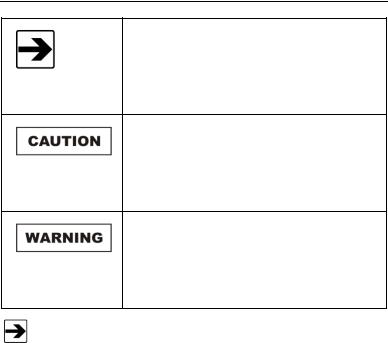
Notes, Cautions, and Warnings
Note: Denotes helpful information intended to provide tips for better use of the product.
Caution: Denotes a hazard. Failure to follow instructions could result in minor personal injury and/or property damage. Included text gives proper procedures.
Warning: Denotes a hazard. Failure to follow instructions could result in SEVERE personal injury and/or property damage. Included text gives proper procedures.
See the ETS-Lindgren Product Information Bulletin for safety, regulatory, and other product marking information.
|ix
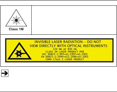
General Safety Considerations
LASER HAZARD. Laser power up to 150 mW at
830 nm may be accessible at the fiber connector of the laser. However, the laser beam itself is not hazardous as the interlock ensures that the exposure time will be less than 30 ms.
See the ETS-Lindgren Product Information Bulletin for safety, regulatory, and other product marking information.
ETS-Lindgren Product Information Bulletin
See the ETS-Lindgren Product Information Bulletin included with your shipment for the following:
Warranty information
Safety, regulatory, and other product marking information
Steps to receive your shipment
Steps to return a component for service
ETS-Lindgren calibration service
ETS-Lindgren contact information
x|
1.0 Introduction
The ETS-Lindgren EMC Field Probes embody the latest innovations in isotropic sensor design and low-noise, miniaturized electronics. Each probe is a fully intelligent sensor enabling fast and accurate EMF measurements with industry-leading performance specifications. Optical coupling to a variety of readout options makes these probes ideally suited for a wide range of field monitoring applications.
The EMC field probes include laser-powered (laser) probes and battery-operated probes. This manual includes operating information and specifications for these probe models:
 Laser-Powered
  HI-6122
HI-6153
HI-6105
 Battery-Operated
  HI-6022
HI-6053
HI-6005
ETS-Lindgren may substitute a similar part or new part number with the same functionality for another part/part number. Contact ETS-Lindgren for questions about part numbers and ordering parts.
Introduction |
| |
11 |

Readout Options
HI-6100 FIELD MONITOR
The HI-6100 Field Monitor accepts inputs from up to any four probes, and analyzes and displays information on a user-configurable LCD.
The HI-6100 may be used in conjunction with both the laser and battery-operated probes.
HI-6100 Field Monitor
For information on using the HI-6100 with ETS-Lindgren probes, see HI-6100 Field Monitor Configuration on page 18.
HI-6113 LASER DATA INTERFACE
The laser probes and the HI-6113 Laser Data Interface together communicate with ProbeView™ Laser software through a USB port on the computer.
HI-6113 Laser Data Interface
For information on using the HI-6113 with ETS-Lindgren probes, see HI-6113 Laser Data Interface Configuration on page 19.
12 |
| |
Introduction |

HI-4413P FIBER OPTIC MODEM
The battery-powered probes use the HI-4413P Fiber Optic Modem to communicate with ProbeView II™ software through a serial port on the computer.
HI-4413P Fiber Optic Modem
For information on using the HI-4413P with ETS-Lindgren probes, see
HI-4413P / HI-4413USB Configuration on page 20.
HI-4413USB FIBER OPTIC TO USB CONVERTER
The battery-powered probes use the HI-4413USB Fiber Optic to USB Converter to communicate with ProbeView II™ software through a USB port on the computer.
HI-4413USB Fiber Optic to USB Converter
For information on using the HI-4413USB with ETS-Lindgren probes, see
HI-4413P / HI-4413USB Configuration on page 20.
Introduction |
| |
13 |

Optional Tripod
The H-491009 Dielectric Tripod is the preferred method for mounting field probes for making unperturbed field measurements. It provides stable placement for one probe, and includes a 1/4–20 UNC threaded stud for mounting any ETS-Lindgren probe with a tripod mount. It is designed with an adjustable center post and a rotating mount.
14 |
| |
Introduction |
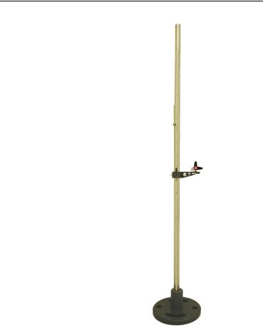
Optional Probe Stand
The ETS-Lindgren Probe Stand may also be used in testing configurations. The probe stand supports up to two probes. For complete information on probe stand assembly and operation, see
H-491269 Probe Stand on page 73.
Introduction |
| |
15 |

About Probe Operation
For information on reducing measurement uncertainties and selecting the best field probe for your application see the white paper Practical Considerations for Radiated Immunities Measurement using ETS-Lindgren EMC Field Probes. This document is located on the ETS-Lindgren website at: www.ets-lindgren.com/whitepapers.
For complete information on setting up and operating the field monitor, software, and other devices available for the laser and battery-operated field probes, please see the documentation provided with those products.
Field probes are nominally rated for operation within a specific frequency range, but may also respond to signals above and below those frequencies. A probe may exhibit response to frequencies below the lower end of the range, and may also respond to frequencies above the upper end of the range, though not consistently or predictably.
Keep all conductive objects away from laser-powered and battery-operated probes. Conductive objects in the proximity of the probe can distort the near field and compromise measurement accuracy. If the application requires measurements from a fixed position, always mount the probe on a non-metallic platform, using non-metallic screws.
16 |
| |
Introduction |

2.0 Typical Configurations
A variety of configurations are available with the field monitors, probes, and other devices. Following are typical examples of how the components can be assembled to accommodate most testing environments.
Typical Configurations |
| |
17 |

HI-6100 Field Monitor Configuration
The following diagram illustrates the ETS-Lindgren probes that may be used with the HI-6100 Field Monitor. In the diagram, the FM in HI-6153FM, for example, refers to Field Monitor Kit. As a kit, the probe includes an interface card.
18 |
| |
Typical Configurations |

HI-6113 Laser Data Interface Configuration
The following diagram illustrates the ETS-Lindgren probes that may be used with the HI-6113 Laser Data Interface (LDI). In the diagram, the USB in HI-6153USB, for example, refers to USB Kit. As a kit, the probe includes all components required to operate the probe with the HI-6113.
Typical Configurations |
| |
19 |

HI-4413P / HI-4413USB Configuration
The following diagram illustrates the ETS-Lindgren probes that may be used with the HI-4413P Fiber Optic Modem or the HI-4413USB Fiber Optic to USB Converter.
20 |
| |
Typical Configurations |
3.0 Maintenance
WARRANTY |
Before performing any maintenance, follow the safety information in the ETS-Lindgren Product Information Bulletin included with your shipment.
Maintenance of probes is limited to external components such as cables or connectors.
Warranty may be void if the housing is opened.
If you have any questions concerning maintenance, contact ETS-Lindgren Customer Service.
If you have one of the following probes, see Probe Shield Care and Replacement on page 81: HI-6122, HI-6022, HI-6105, or HI-6005 Field Probe.
Annual Calibration
See the Product Information Bulletin included with your shipment for information on ETS-Lindgren calibration services.
Maintenance |
| |
21 |
Laser Probes and Maintenance of Fiber Optics
The fiber optic connectors and cables used with laser-powered probes can be damaged from airborne particles, humidity and moisture, oils from the human body, and debris from the connectors they plug into. Always handle connectors and cables with care, using the following guidelines.
Before performing any maintenance, disconnect the fiber optic cables from the unit and turn off power.
When disconnecting fiber optic cables, apply the included dust caps to the ends to maintain their integrity.
Before connecting fiber optic cables, clean the connector tips and in-line connectors.
Before attaching in-line connectors, clean them with moisture-free compressed air.
Failure to perform these tasks may result in damage to the fiber optic connectors or cables.
Upgrade Policies
Periodically, probes are upgraded to enhance functionality. Contact ETS-Lindgren Customer Service for the upgrade status of your probe.
Service Procedures
For the steps to return a system or system component to ETS-Lindgren for service, see the Product Information Bulletin included with your shipment.
22 |
| |
Maintenance |

4.0 Laser-Powered Field Probes
The HI-61XX Series LaserPro™ Field Probe is a laser-powered probe, an excellent tool for electric field mapping, industrial monitoring, and EMC field measurements.
The HI-61XX Series probes contain a photo-voltaic converter that provides power to the probe circuitry when sufficient light power is received by the converter. The light power is generated by a laser in the HI-6113 Laser Data Interface, and is transmitted to the converter through an optical fiber in the duplex fiber optic cable. The probe communicates with the HI-6113 through this fiber optic cable. Receiving power from the HI-6113 allows for unlimited test times.
The probe system incorporates a safety interlock mechanism that turns off the laser if the HI-6113 does not receive data from the probe within a specified time frame. The safety mechanism is intended to prevent injury from the laser if the HI-6113 issues a command to turn on the laser while the fiber optic cables are disconnected, improperly connected, cut, or damaged.
The laser driver in the HI-6100 Field Monitor also incorporates this safety interlock mechanism, and operates in the same manner.
The HI-6100 Field Monitor may also be used with the HI-61XX Series for RFI/EMC testing. For more information on readout options, see page 12.
Laser-Powered Field Probes |
| |
23 |

HI-6122 Electric Field Probe
|
|
|
|
The ETS-Lindgren HI-6122 Field Probe |
|
|
|
|
provides broadband frequency coverage |
|
|
|
|
and wide dynamic range that satisfies the |
|
|
|
|
demands of most test requirements. |
|
|
|
|
The frequency response of the HI-6122 is |
|
|
|
|
10 kHz to 1 GHz, and the dynamic range is |
|
|
|
|
2 to 800 Volts per meter (V/m). |
HI-6122 SPECIFICATIONS |
|
|||
|
|
|
|
|
|
|
Dynamic Range: |
|
2.0 – 800 Volts per meter (V/m) |
|
|
|
|
|
|
|
|
|
|
|
|
Ranges: |
|
Single |
|
|
|
|
|
|
|
|
|
|
|
|
Typical Frequency Response: |
|
10 kHz–1 GHz |
|
|
|
||
|
|
|
|
10 kHz–30 kHz: +0.5 dB, -2.5 dB |
|
|
|
|
|
|
|
|
|
30 kHz–1 GHz: ±1 dB |
|
|
|
|
|
|
|
Typical Frequency Response |
|
10 kHz–1 GHz: ±0.9 dB |
|
|
|
||
|
|
with Correction: |
|
|
|
|
|
|
|
|
|
|
|
|
|
|
|
|
|
|
|
Linearity: |
|
±0.5 dB @ 27 MHz |
|
|
|
|
|
|
|
|
|
|
|
|
Isotropicity: |
|
±0.5 dB @ 400 MHz |
|
|
|
|
|
|
|
|
|
|
|
|
Overload Withstand: |
|
> 1,500 V/m CW |
|
|
|
|
|
|
|
|
|
|
24 | |
Laser-Powered Field Probes: HI-6122 Electric Field Probe |
|
Physical Interface: |
|
Duplex optical fiber |
|
|
||
|
|
||
|
|
|
(62.5 micron multimode) |
|
|
|
FC connectors for laser cable, |
|
|
|
integral 1-m optical cable |
|
|
|
ST connector for transmitter cable, |
|
|
|
integral 1-m optical cable |
|
|
|
|
|
|
|
|
|
Probe Mount: |
|
1/4–20 UNC tapped hole (internal thread) |
|
|
|
|
|
|
|
|
|
Environmental |
||
|
|
|
|
|
Operating Temperature: |
|
10°C to 40°C |
|
|
||
|
|
|
50°F to 104°F |
|
|
|
|
|
|
|
|
|
Humidity: |
|
5% to 95% relative humidity, |
|
|
||
|
|
|
non-condensing |
|
|
|
|
|
|
|
|
|
Dimensions |
||
|
|
|
|
|
Housing: |
|
32 mm x 32 mm x 32 mm |
|
|
||
|
|
|
1.26 in x 1.26 in x 1.26 in |
|
|
|
|
|
|
|
|
|
|
|
|
|
|
|
|
|
Probe Shields: |
|
36 mm (1.42 in) |
|
|
|
|
|
|
|
|
|
Weight: |
|
80 g (2.82 oz) |
|
|
|
|
|
|
|
|
HI-6122 OPERATION
The HI-6122 can be used with the HI-6100 Field Monitor. It can also be connected to a personal computer using an optional HI-6113 Laser Data Interface and ProbeView™ Laser software.
The HI-6122 is a true 3-axis probe. When requested, X, Y, Z, and total field data can be reported.
For a list and description of communication and information transfer protocols, including command structure, probe commands, and HI-6113 commands, see
Appendix D: Operating Protocols on page 101.
Laser-Powered Field Probes: HI-6122 Electric Field Probe |
| |
25 |

HI-6122 TYPICAL FREQUENCY RESPONSE
TEM Cell and GTEM! – Field Level 20 V/m
26 | |
Laser-Powered Field Probes: HI-6122 Electric Field Probe |

HI-6122 TYPICAL ISOTROPIC RESPONSE
Isotropic response measured in a 20 V/m field at 400 MHz.
Laser-Powered Field Probes: HI-6122 Electric Field Probe |
| |
27 |

HI-6122 ADDITIONAL MAINTENANCE
Maintenance of the HI-6122 is limited to external components such as cables, connectors, and probe shields. For information on fiber optic cable and connector maintenance, see Laser Probes and Maintenance of Fiber Optics on page 22. To replace the probe shields, see Probe Shield Care and Replacement on page 81.
Any maintenance or calibration task requires probe disassembly, which may void your warranty. Only ETS-Lindgren service personnel should perform these tasks. To avoid problems with your warranty, contact ETS-Lindgren Customer Service before performing any maintenance.
For complete information on maintenance and calibration, see Maintenance on page 21.
HI-6122 ADDITIONAL PARTS
Use the following table to order replacement or optional parts for the HI-6122.
|
Part Description |
|
|
Part Number |
|
||
|
|
|
|
||||
|
|
|
|
|
|
||
|
|
|
|
|
|
||
|
Probe shield replacement Kit |
|
112955 |
|
|||
|
includes: |
|
|
|
|
|
|
|
Three probe shields (cones) |
|
|
|
|
||
|
One each X, Y, and Z label |
|
|
|
|
||
|
|
Six screws |
|
|
|
|
|
|
|
|
|
|
|||
|
Cable Assembly, Fiber, FC-FC, |
|
|
H-491263-xx |
|||
|
ST-ST |
|
|
|
(xx=length in meters) |
||
|
|
|
|
|
|
||
|
|
|
|
|
|||
|
FC to FC Inline Connector |
|
|
H-23861521000 |
|||
|
|
|
|
|
|||
|
ST to ST Inline Connector |
|
708027 |
|
|||
|
|
|
|
|
|||
|
Carrying Case |
|
|
H-491291 |
|||
|
|
|
|
|
|||
|
HI-6100 Field Monitor |
|
|
HI-6100 |
|||
|
|
|
|
||||
28 |
| |
Laser-Powered Field Probes: HI-6122 Electric Field Probe |
|||||
|
Part Description |
|
|
Part Number |
|
|
|
|
|
||
|
|
|
|
||
|
|
|
|
|
|
|
|
|
|
|
|
|
Laser Data Interface |
|
|
HI-6113 |
|
|
|
|
|
|
|
|
Tripod, Dielectric |
|
|
H-491009 |
|
|
|
|
|
|
|
|
Probe Stand |
|
|
H-491269 |
|
|
|
|
|
|
|
|
Fiber Optic Cleaning System |
|
|
H-34FO1 |
|
|
|
|
|
|
|
|
Laser System Fiber Optic |
|
112333 |
|
|
|
Maintenance Kit |
|
|
|
|
|
|
|
|
|
|
|
Probe Carrier for H-491269 |
|
|
H-491276 |
|
|
Probe Stand |
|
|
|
|
|
|
|
|
|
|
Laser-Powered Field Probes: HI-6122 Electric Field Probe |
| |
29 |

HI-6153 Electric Field Probe
The ETS-Lindgren HI-6153 Field Probe provides broadband frequency coverage and wide dynamic range that satisfies the demands of most test requirements.
The frequency response of the HI-6153 is 10 MHz to 40 GHz, and the dynamic range is 2 to 800 Volts per meter (V/m).
HI-6153 SPECIFICATIONS
|
Dynamic Range: |
|
2.0–800 Volts per meter (V/m) |
|
|
|
|||
|
|
|
|
|
|
Ranges: |
|
|
Single |
|
|
|
||
|
|
|
|
|
|
|
|
|
|
|
Typical Frequency Response: |
|
10 MHz–40 GHz |
|
|
|
|
|
10 MHz–100 MHz: +3 dB, -4 dB |
|
|
|
|
|
|
|
|
|
100 MHz–1 GHz: +3 dB, -0.5 dB |
|
|
|
|
1 GHz–18 GHz: +4 dB, -2 dB |
|
|
|
|
18 GHz–40 GHz: +3.5 dB, -4.5 dB |
|
|
|
|
|
|
|
|
|
|
|
Typical Frequency Response |
|
10 MHz–18 GHz: ± 0.9 dB |
|
|
with Correction: |
|
||
|
|
18 GHz–40 GHz: ± 1.1 dB |
||
|
|
|
|
|
|
|
|
|
|
|
|
|
|
|
|
Linearity: |
|
|
±0.5 dB @ 1 GHz |
|
|
|
||
|
|
|
||
|
|
|
|
|
|
Isotropicity: |
|
±1.0 dB < 18 GHz |
|
|
|
|||
|
|
|
|
|
30 | |
Laser-Powered Field Probes: HI-6153 Electric Field Probe |
|||
Loading...