

Page 1

Sample Draw
Monitoring System
Oxygen
(OMS)
User Manual
www.fmgrupotec.com fmgrupotec@fmgrupotec.com 0034.903.360.306 Calle Algepser n16 Parque Empresarial Tactica- 46980 Paterna (Valencia)- España
Page 2

ETS-Lindgren Inc. reserves the right to make changes to any product described
herein in order to improve function, design, or for any other reason. Nothing
contained herein shall constitute ETS-Lindgren Inc. assuming any liability
whatsoever arising out of the application or use of any product or circuit
described herein. ETS-Lindgren Inc. does not convey any license under its
patent rights or the rights of others.
© Copyright 2013 by ETS-Lindgren Inc. All Rights Reserved. No part of this
document may be copied by any means without written permission from
ETS-Lindgren Inc.
Trademarks used in this document: The ETS-Lindgren logo and OMS are
trademarks of ETS-Lindgren Inc.; NEMA is a registered trademark of NEMA;
3M and Scotch-Brite are trademarks of 3M.
Revision Record
MANUAL,OXYGEN DEFICIENCY MONITOR | Part #399374, Rev. B
Revision
A
Description
Initial Release
Date
August, 2013
B
www.fmgrupotec.com fmgrupotec@fmgrupotec.com 0034.903.360.306 Calle Algepser n16 Parque Empresarial Tactica- 46980 Paterna (Valencia)- España
Updated Introduction; added
installation location information;
added Sample Draw Sensor
Tubing
December, 2013
Page 3

Table of Contents
www.fmgrupotec.com fmgrupotec@fmgrupotec.com 0034.903.360.306 Calle Algepser n16 Parque Empresarial Tactica- 46980 Paterna (Valencia)- España
Notes, Cautions, and
1.0
Introduction .......................................................................... 9
Technology ................................................................................................. 9
Long-Life Zirconium Oxide Sensor Cell ............................................... 9
Smart Electronics.............................................................................. 10
Standard Configuration ............................................................................. 10
Optional Remote Display .......................................................................... 10
Other Optional Items................................................................................. 11
ETS-Lindgren Product Information Bulletin ............................................... 11
2.0
Maintenance ....................................................................... 13
Recommended Routine Maintenance ....................................................... 14
Every 6-12 Months ............................................................................ 14
Annually............................................................................................ 14
Replacement and Optional Parts .............................................................. 15
Service Procedures .................................................................................. 15
3.0
Specifications..................................................................... 17
Electrical Specifications ............................................................................ 17
Physical Specifications ............................................................................. 17
Performance Specifications ...................................................................... 18
Gas Detection System Specifications........................................................ 18
Signal Outputs .......................................................................................... 19
Default Factory Settings............................................................................ 19
4.0 Component
Front View Exterior ................................................................................... 21
Front View, Cover Removed ..................................................................... 23
Transmitter Interior ................................................................................... 25
Alarm Relay Board.................................................................................... 26
5.0 Before You Begin
Site Requirements .................................................................................... 27
Connect to 24 VDC Regulated Power ....................................................... 28
Connect OMS and Sensor Before Powering ............................................. 28
Warnings.............................................. vii
Views .............................................................. 21
Installation........................................... 27
Page 4

Do Not Exchange the Sensor Electronics.................................................. 28
Use Proper Calibration Steps.................................................................... 28
Keep Away From Silicone Compounds ..................................................... 29
Keep Away From High Air Flow ................................................................ 29
Keep Away From a Water Stream............................................................. 30
6.0
Installation ..........................................................................
Mounting the OMS .................................................................................... 31
Transmitter and Sensor..................................................................... 32
Enclosure Mounting Feet .................................................................. 33
Dust Filter ......................................................................................... 34
Sample Draw Sensor Tubing .................................................................... 35
Using an Available Waveguide.......................................................... 36
Using Kit 551060 to Install Waveguide .............................................. 37
Wiring ....................................................................................................... 39
Installing the Optional Remote Display...................................................... 40
Connecting a Remote Horn and Strobe to OMS........................................ 42
Connecting a Remote Fan Contactor to OMS ........................................... 43
Initial Startup............................................................................................. 44
7.0
Operation ............................................................................
Joystick Operation .................................................................................... 47
Main Operation Mode ............................................................................... 48
Internal Sample Flow Rate........................................................................ 48
Signal Outputs .......................................................................................... 48
Instrument Faults ...................................................................................... 49
Loss of Power Indicator ............................................................................ 50
Alarm Reset .............................................................................................. 50
8.0 Programming the
Program Flowchart ................................................................................... 52
Passwords ................................................................................................ 57
Enter Password ................................................................................ 57
Change Password............................................................................. 58
Enable/Disable Password Function ................................................... 59
Main Menus and Submenus ..................................................................... 60
Set 4–20 mA Loop ............................................................................ 60
OMS ......................................................
31
47
51
www.fmgrupotec.com fmgrupotec@fmgrupotec.com 0034.903.360.306 Calle Algepser n16 Parque Empresarial Tactica- 46980 Paterna (Valencia)- España
Page 5

Set Formats ...................................................................................... 61
www.fmgrupotec.com fmgrupotec@fmgrupotec.com 0034.903.360.306 Calle Algepser n16 Parque Empresarial Tactica- 46980 Paterna (Valencia)- España
Page 6

Set Alarm Threshold Parity ............................................................... 63
Set Latching...................................................................................... 65
Reset Latching Alarm........................................................................ 66
Set Alarm Delay ................................................................................ 67
Set Zero Suppression ....................................................................... 67
Set Alarm Thresholds ....................................................................... 68
Set Alarm Hysteresis ........................................................................ 70
Set Sensor Adjust ............................................................................. 72
9.0 Sensor
Required Gas and Equipment ................................................................... 74
Sensor Verification Procedure .................................................................. 74
Sensor Verification to Nitrogen.................................................................. 75
Sensor Verification to Known Concentration of Oxygen ............................ 76
Appendix A:
Verification ............................................................
Warranty .............................................................
73
77
www.fmgrupotec.com fmgrupotec@fmgrupotec.com 0034.903.360.306 Calle Algepser n16 Parque Empresarial Tactica- 46980 Paterna (Valencia)- España
Page 7

This page intentionally left blank.
www.fmgrupotec.com fmgrupotec@fmgrupotec.com 0034.903.360.306 Calle Algepser n16 Parque Empresarial Tactica- 46980 Paterna (Valencia)- España
Page 8

Page 9
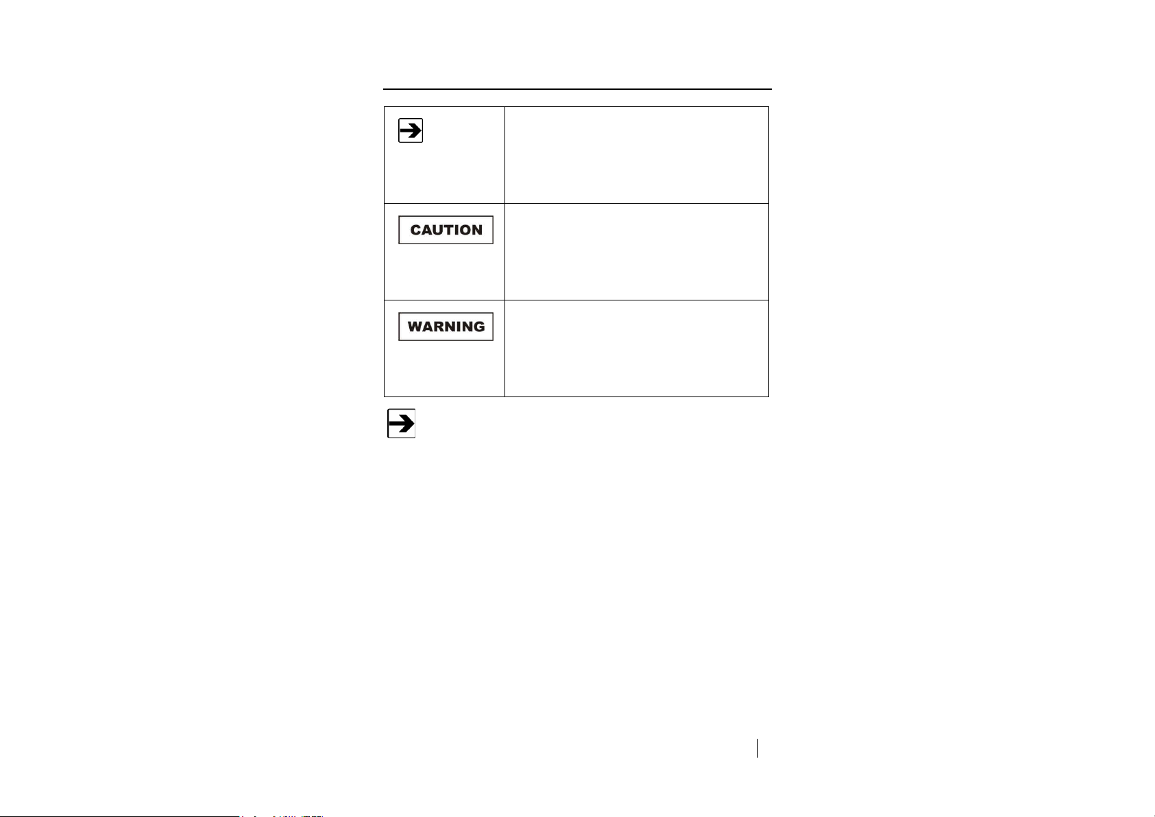
Notes, Cautions, and Warnings
Note: Denotes helpful information intended to
See the ETS-Lindgren Product Information Bulletin for safety,
regulatory, and other product marking information.
provide tips for better use of the product.
Caution: Denotes a hazard. Failure to follow
instructions could result in minor personal injury
and/or property damage. Included text gives proper
procedures.
Warning: Denotes a hazard. Failure to follow
instructions could result in SEVERE personal injury
and/or property damage. Included text gives proper
procedures.
www.ets-lindgren.com
vii
Page 10

This page intentionally left blank.
Page 11

1.0 Introduction
The ETS-Lindgren Sample Draw Oxygen Monitoring System (OMS™) is a
self-contained oxygen deficiency detection system suitable for remote sampling
of confined spaces; this single-point monitor is designed for the continuous
detection and measurement of ambient oxygen concentration levels.
As a compact gas monitoring system, the OMS is ideal for the continuous
monitoring of the air in MRI rooms, labs, freezers, confined spaces, and other
shielded enclosures where inert gases may displace the oxygen and create a
danger for patients and staff. The OMS is suitable for indoor and outdoor use,
and is intended to be installed outside of the shielded enclosure.
Each system consists of a long-life zirconium oxide sensor cell and 3-wire
transmitter. Unlike electrochemical sensor cells, the zirconium oxide sensor cell
provides stable oxygen readings even in areas where temperature and humidity
levels are changing. The OMS may be used as a standalone gas detector or
connected to your own centralized control and surveillance system.
Technology
L
ONG-LIFE ZIRCONIUM OXIDE SENSOR CELL
The heart of the monitoring system is a zirconium sensor, which responds to low
oxygen conditions within seconds and provides accurate measurements over a
wide temperature and humidity range. The zirconium sensor will operate
continuously for eight or more years, requiring minimum maintenance. There are
no zero or span calibration pots to adjust, and when compared to disposable
sensors, the long-life zirconium sensor can save hundreds of dollars in annual
maintenance.
Unlike concentration cells, the zirconium sensor does not need an oxygen
reference gas for proper operation. The OMS can detect low oxygen levels in
confined spaces and process tools without the need of a reference gas.
Page 12
S
MART ELECTRONICS
The OMS incorporates a special electronic circuit that continuously monitors
sensor operation. With the addition of the alarm relay option, any cell degradation
or complete failure will be detected immediately. This smart circuitry alerts the
user to sensor faults and other electrical problems that may interrupt surveillance
through the standard mA signal output signal or through the optional fault relay
option.
Ideal for continuously monitoring oxygen levels in confined spaces or areas
where inert gases are used, the OMS does not drift or lose sensitivity with
weather or temperature changes. The electronics are housed in a
NEMA Type 4X enclosure.
Standard Configuration
The OMS must be installed outside of the shielded enclosure.
• Oxygen Monitoring System
• Power supply
• Dust filter
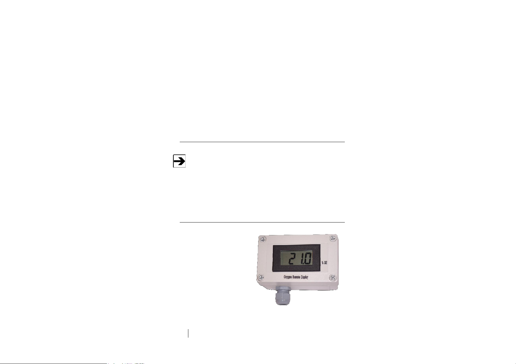
Optional Remote Display
The remote display receives oxygen
concentration information from
the OMS. Up to two remote displays
can be connected. See page 40 for
installation information.
Page 13

Other Optional Items
• Remote Horn and Strobe
• Waveguide Installation Kit
ETS-Lindgren Product Information Bulletin
See the ETS-Lindgren Product Information Bulletin included with your shipment
for the following:
• Warranty information
• Safety, regulatory, and other product marking information
• Steps to receive your shipment
• Steps to return a component for service
• ETS-Lindgren calibration service
• ETS-Lindgren contact information
Page 14

This page intentionally left blank.
Page 15
2.0 Maintenance
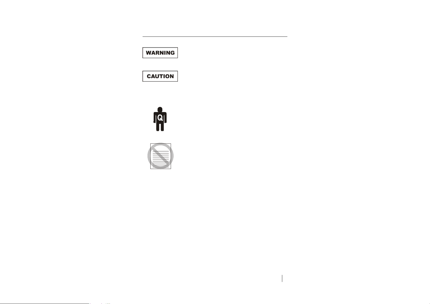
WARRANTY
Calibrate or challenge the OMS ONLY outside
the MRI suite.
Before performing any maintenance, follow the
safety information in the ETS-Lindgren
Product Information Bulletin included with your
shipment.
Maintenance of the OMS is limited to the
procedures described in this manual, and
should be performed only by qualified
personnel.
Warranty may be void if non-authorized
procedures are performed, or if performed by
non-qualified personnel.
If you have any questions concerning
maintenance, contact ETS-Lindgren
Customer Service.
13
Page 16

Recommended Routine Maintenance
The Sample Draw Oxygen Monitoring System (OMS™) is a continuous gas
detection system that measures and detects hazardous gas leaks in the
workplace, and therefore requires periodic maintenance to ensure proper
operation. The frequency with which this routine maintenance is performed
depends on your environment and company policies. Following are
recommendations intended as a general guideline.
E
VERY
6-12 M
ONTHS
• Visual checks: Check for power and proper operation. The OMS
should output a 17.34 mA signal when the oxygen level is at 20.9%.
Also, the display should indicate 20.9% oxygen when the oxygen is at
A
ambient levels.
• Sensor verification with nitrogen: The ambient oxygen level is
20.9%; therefore, under ambient conditions verification of the OMS to
20.9% oxygen is constantly performed. The OMS requires periodic
testing with nitrogen only to verify the cell response to low oxygen
levels. See Sensor Verification on page 73 for detailed steps.
NNUALLY
Depending on the environment, the filter should be replaced every 12 months; in
dusty environments, the filter may need to be replaced more frequently. If the
filter becomes completely blocked, the internal flow sensor will detect the loss of
flow and activate the fault relay and LED.
14
Maintenance
Page 17
Replacement and Optional Parts
ETS-Lindgren may substitute a similar part or new part number with
the same functionality for another part/part number. Contact
ETS-Lindgren for questions about part numbers and ordering parts.
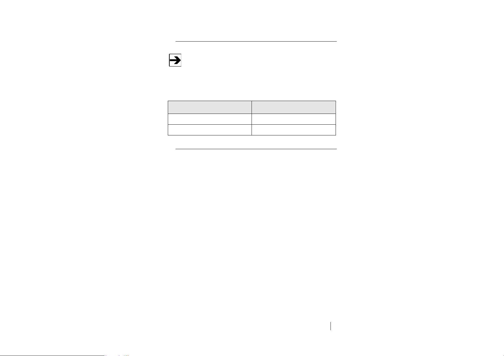
Following are the part numbers for ordering replacement or optional parts for
the OMS.
Part Description
Part Number
Optional Remote Display
Filter Replacement
Service Procedures
250552
250551
For the steps to return a system or system component to ETS-Lindgren for
service, see the Product Information Bulletin included with your shipment.
15
Page 18

This page intentionally left blank.
16
Maintenance
Page 19
3.0 Specifications
Electrical Specifications
A regulated 24 VDC power supply is required.
Power:
24 VDC external power
Consumption:
Approximately 700 mA
Physical Specifications
Height:
Width:
Depth:
Weight:
Enclosure Type:
7.0 in (178 mm)
5.0 in (127 mm)
5.0 in (127 mm)
4.0 lb (2 kg)
NEMA Type 4X wall mount general
purpose; not intended for explosive
atmospheres or
electrically-classified areas
17
Page 20

Performance Specifications
Sensor Type:
Long-life zirconium oxide
sensor cell, 0%–25%
Response Time:
Repeatability:
Fault Indicators:
Operating Temperature:
Humidity:
Within 2 seconds of any change in
oxygen
± 2% of reading
• Loss of VDC power
(analog signal drops to 0 mA).
• Sensor cell failure: fault relay
activated
-40°C to + 40°C (40°F to 104°F)
Contact ETS-Lindgren for lower or
higher operating temperatures
0% to 95% relative humidity (RH)
Contact ETS-Lindgren for sensors
which can operate in 100%
condensing RH environments
Gas Detection System Specifications
Type:
Sensor Life:
Long-life zirconium oxide
sensor cell, 0%–25%
8 to10 years, under normal
conditions
Transmitter:
18
Specifications
• Microprocessor electronics with
built-in 3-digit backlit LCD display
• Joystick-operated menus
Page 21
Signal Outputs
Local Display: Digital display calibrated for
The range is stated on the serial number and can be accessed via
the joystick on the front panel. In the measurement mode push the
joystick down to scroll the gas and range on the display. Push the
joystick down again to stop the scrolling and re-display the gas.
Standard:
oxygen.
Analog Output: DC 4–20 mA
Optional:
Default Factory Settings
• Relay Output: Dual level
user-selectable alarm relays and
one fault relay
• Rated: 2 amps @ 30 VDC;
2 amps @ 240 VAC
The built-in relay settings are user-changeable; see Main Menus and
Submenus on page 60 for more information.
Menu Function / Description
Set 4–20 mA loop
To set the OMS 4 mA (zero) and 20 mA
(span) to your PLC or distributive control
system.
Set Formats; LED and Alarm Relay State
To set the relays to energize (normal) or
de-energize (fail safe) when the alarm
activates.
Note: The LED indicators on the front panel
are connected directly to the alarm relays.
Factory Default
The mA output is set at the
factory using a calibrated
Fluke meter.
Alarm 1 = Normal
Alarm 2 = Normal
Fault = Normal
19
Page 22

Menu Function / Description
Factory Default
Set Alarm Threshold Polarity
To set to alarm at a level higher (normal) or
lower (inverted) than the alarm threshold.
Note: The Audio Alarm feature is optional.
Set Latching
To set the alarm to automatically reset
(non-latching) or to manually reset
(latching).
Alarm Delay
To set the time to wait until the relay alarms
activate.
Zero Suppression
Note: This function is not enabled on
the OMS.
Set Alarm Thresholds
To set the level to alarm.
Note: The Audio Alarm feature is optional.
Set Alarm Hysteresis
Use when utilizing the OMS for control or
valves and process; see page 70 for more
information.
Alarm 1 = Inverted
Alarm 2 = Inverted
Audio = Inverted
Alarm 1 = Non-latching
Alarm 2 = Non-latching
Audio = Non-latching
Alarm = 5 seconds
000 = 0.00%
Alarm 1 = 19.5 %
Alarm 2 = 18.0 %
Audio = 19.5%
Alarm 1 = 0.0 %
Alarm 2 = 0.0 %
Audio = 0.0 %
Sensor Adjustment
No factory default
For use when dynamically gas calibrating
the OMS to a known span gas; see page 72
for more information.
Manage Passwords
Factory default is 557
To change the password from the factory
default to a new password.
20
Specifications
Page 23
4.0 Component Views
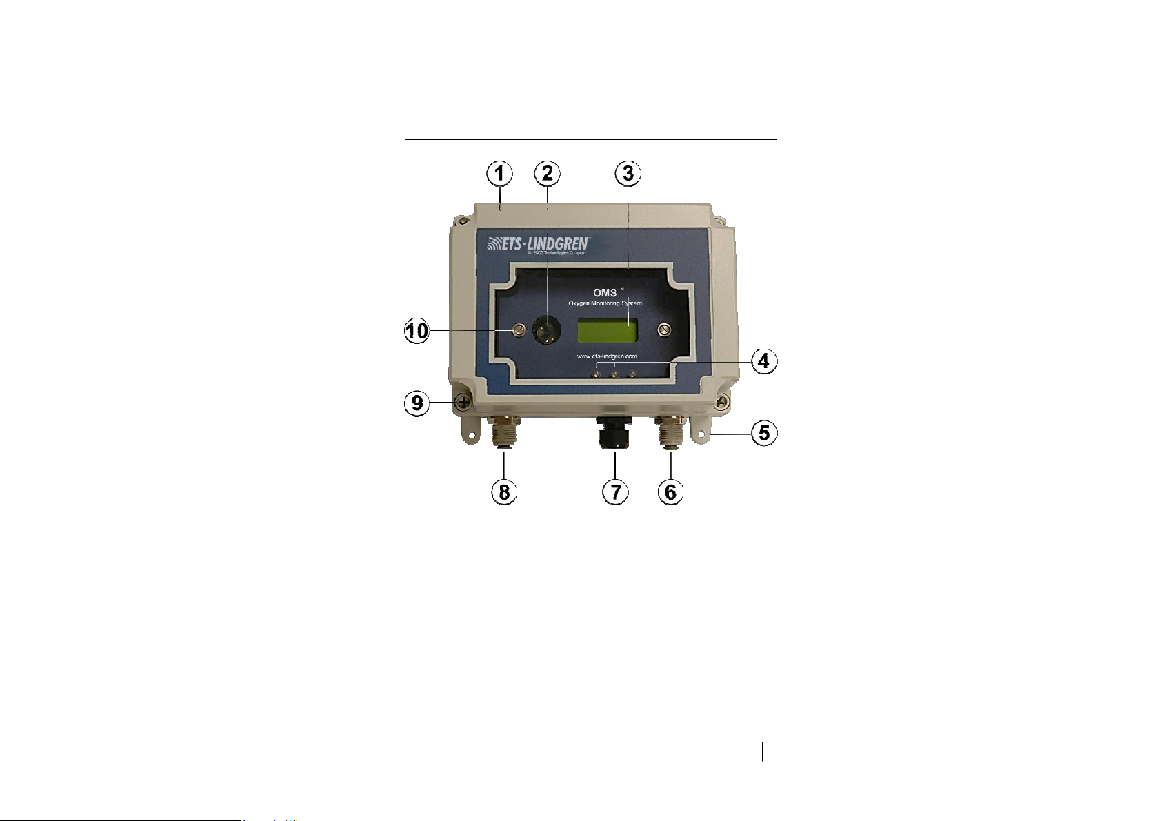
Front View Exterior
1. Front cover—Removable, waterproof cover that protects the interior of
the transmitter; fastened by four captive screws.
2. Joystick—Used to select and adjust the built-in menus. The OMS
features dual level user-selectable alarms.
3. Digital display—Displays the oxygen levels in percentage; the normal
oxygen level on Earth is 20.9%.
Component Views
21
Page 24

4. Alarm relay LEDs—Three multi-colored LED indicators,
from left to right:
• Alarm 2—Red
• Alarm 1—Orange
• Fault—Yellow
5. Mounting feet (4)
6. Sample inlet—Permits the flow of oxygen to enter the sensor.
7. Cable strain relief—The sealed opening in the transmitter housing for
connecting the input power, 4–20 mA output, and relay wiring.
8. Sample exhaust—Permits the flow of oxygen to exit the enclosure.
9. Front cover fasteners (4)—Four captive screws attach the front
window to the base unit.
10. Front panel fastening screws (2)
22
Component Views
Page 25

Front View, Cover Removed
1. Sample pump—Brings in a sample to the sensor. Flow rate is preset
at the factory, and is continuously protected with a built-in flow sensor.
For more information, see Instrument Faults on page 49.
2. Sensor assembly—A zirconium oxide sensor cell that detects and
measures the level of oxygen. When exposed to oxygen, the sensor
outputs an electrical signal proportional to the actual concentration of
oxygen.
3. Retaining screws for electronics panel (2)—These mount the
display front panel and electronics to the enclosure.
When unfastening the front panel electronics, apply upwards pressure
on the back of the front panel to release the captive screw.
Component Views
23
Page 26

Front view with electronics panel rotated
24
Component Views
Page 27

Transmitter Interior
The fuse is field-replaceable.
The power analog output terminal block is a 5-pin terminal block where the
24 VDC power and 4–20 mA analog output connections are made.
Component Views
25
Page 28

Alarm Relay Board
For the relays, from left to right:
NC – C – NO
26
Component Views
Page 29

5.0 Before You Begin Installation
Before installing or connecting any
components, follow the safety information in
the ETS-Lindgren Product Information Bulletin
included with your shipment.
Failure to follow the instructions in this chapter
Site Requirements
The OMS must be installed outside of the shielded enclosure.
The Sample Draw Oxygen Monitoring System (OMS™) enclosure should be
mounted in an area free of vibration and electrical noise or interference. If
possible, avoid areas with high temperatures or condensing humidity.
may damage the OMS and/or the sensor.
The OMS is not designed for installation in a
hazardous area. Contact ETS-Lindgren for
information on special enclosures for use in a
hazardous environment.
The OMS must be installed outside of the
MRI room; otherwise, the OMS may interfere
with the normal operation of the MRI system.
www.ets-lindgren.com
Before You Begin Installation
27
Page 30

Connect to 24 VDC Regulated Power
The OMS requires 24 VDC regulated
power.
WARRANTY
Connect OMS and Sensor Before Powering
Do Not Exchange the Sensor Electronics
Do not connect the OMS to any voltage
that exceeds 24 Volts DC.
Do not connect the OMS to any
AC voltage.
To avoid damage to the sensor:
• Do not power the OMS with the sensor
unplugged from the main PC board.
• Do not connect the sensor to the PC board while
the OMS is powered.
The sensor is matched to the electronics. Never
exchange the electronics with a sensor from a
different OMS.
Use Proper Calibration Steps
Calibrate or challenge the OMS ONLY outside
the MRI suite.
28
Before You Begin Installation
www.ets-lindgren.com
Page 31

When calibrating or challenging the OMS:
• Do not expose the OMS to flow rates that exceed
a half-liter per minute (500 cc per minute).
• When testing sample draw monitors use an
on-demand regulator to expose the span gas to
the OMS.
• Expose the OMS to span gas blends that only
consist of oxygen and nitrogen. Do not expose
the OMS to any combustible gas (methane,
hydrogen, etc.). Exposure to combustible
span gases can damage the sensor.
Keep Away From Silicone Compounds
Do not expose the OMS to silicone compounds.
Exposure to silicone compounds can cause a
loss of sensitivity.
Keep Away From High Air Flow
Do not expose the OMS to high air flow or
install it directly in front of fans. High air flow
can cool the sensor and cause inaccurate
readings.
www.ets-lindgren.com
Before You Begin Installation
29
Page 32

Keep Away From a Water Stream
Do not expose the sensor directly to a water
stream. Cover and protect the OMS and power
supply if located in an area that requires
wash downs.
Contact ETS-Lindgren for information on purchasing a waterproof
enclosure.
30
Before You Begin Installation
www.ets-lindgren.com
Page 33

6.0 Installation
Before connecting any components, follow the
safety information in the ETS-Lindgren
Product Information Bulletin included with your
shipment.
Prior to performing any of the steps in this
chapter, see Before You Begin Installation on
page 27.
The OMS must be installed outside of the
MRI room; otherwise, the OMS may interfere
with the normal operation of the MRI system.
The OMS must be installed outside of the shielded enclosure.
Mounting the OMS
The Sample Draw Oxygen Monitoring System (OMS™) is designed primarily for
wall mounting and should be installed at a height convenient for operation,
maintenance, and viewing of the instrument display. The transmitter and sensor
should be installed in a location where gas leaks are likely to occur or where
released gases may accumulate.
www.ets-lindgren.com
Installation
31
Page 34

T
RANSMITTER AND SENSOR
Leave clearance room on the bottom of the OMS for the filter, which
adds an additional 3.75 inches.
The OMS should be mounted no closer than 12 inches above floor level. Airflow
within the monitored area, the characteristics of the gas (lighter or heavier than
air), and the position of workstations and personnel should all be considered in
determining the most suitable installation location.
32
Installation
www.ets-lindgren.com
Page 35

E
NCLOSURE MOUNTING FEET
The four mounting feet can be oriented in any direction. The feet can also be
removed for mounting the OMS flush with a wall or other surface.
www.ets-lindgren.com
Installation
33
Page 36

D
UST FILTER
To protect the pump from dust, a particulate filter is provided.
1. Attach the filter to the sample inlet by inserting the filter into the 1/4-in
34
tube compression fitting.
2. Verify the correct flow by aligning the arrow towards the OMS.
Installation
www.ets-lindgren.com
Page 37

Sample Draw Sensor Tubing
A penetration panel area contains active
electrical equipment and connections; contact
with this equipment can be life threatening.
Installation must be performed by a qualified
individual.
Run transparent polyurethane 1/4-in (7-mm) tubing (not included) a
maximum of 100 feet (30 meters) from the display unit, through a
waveguide, and into the interior of the MRI room or shielded
enclosure.
The OMS flow pump continuously samples air drawn from end points up to a
maximum of 100 feet (30 meters) from the unit. For optimal sensing, position the
end point of the tube near the ceiling of the monitored space. A tuned pipe
waveguide allows the tubing to enter the shield but attenuates electromagnetic
interference (EMI) from entering.
www.ets-lindgren.com
Installation
35
Page 38

U
SING AN AVAILABLE WAVEGUIDE
(Magnet penetration panel area shown)
1. In the equipment room locate the penetration panel and determine if
there is an available waveguide port. Any unused pipe waveguide with
a 1/2-in diameter or greater can be used. If there is no waveguide
36
available, go to page 37 to install Waveguide Kit 551060.
2. If one of the following types of waveguides is available, then route the
sensor tubing through and into the MRI room or other shielded
enclosure:
• If a threaded pipe waveguide is available: Install standard threaded
plastic bushings to ensure that the sensor tubing is not abraded over
time.
• If a medical gas port that consists of a copper tube is available:
Use a type of grommet to protect each end of the waveguide tube.
Installation
www.ets-lindgren.com
Page 39

U
SING KIT
551060
TO INSTALL WAVEGUIDE
The Waveguide Kit 551060 includes the following:
• 1/2-in threaded brass pipe waveguide (1 each)
• 1/2-in brass bee nuts (2 each)
To prevent linen dust or other airborne particulate matter from
clogging the sensor tubing, use a small filtered terminus that can be
serviced easily.
1. Locate the area in the penetration panel to place the 1/2-in pipe
www.ets-lindgren.com
waveguide.
2. Using a hole saw with the same inner diameter as the 1/2-in pipe
waveguide outer diameter, gently cut through the copper shielding.
This can be done by hand-rotating the hole saw in reverse, or by
marking the copper and using a box cutter to remove the copper.
3. Cut through the plywood with the hole saw.
Installation
37
Page 40

4. Use a 3M™ Scotch-Brite™ pad or fine steel wool to clean the copper
surface where the waveguide will pass through the shield; do not use
sandpaper.
5. Run one of the brass bee nuts down to the approximate half-point of
the waveguide.
Slide the 12-oz copper washer onto the waveguide so that it will rest
between the copper shield face and the bee nut.
Insert the waveguide.
6. On the inside of the shield install the second bee nut and hand tighten.
On the outside of the shield grip the waveguide and tighten the bee to
a snug torque.
7. Route the 1/4-in sensor tubing through the waveguide.
8. For an MRI room: Inside the MRI room, route the sensor tubing along
the inside of the finished ceiling to a point above the magnet, or to a
point between the top of the magnet and a return air grill.
38
Installation
www.ets-lindgren.com
Page 41

Wiring
A 3-wire shielded cable: 3-conductor, 18 AWG stranded
General Cable E2203S.30.860, or equivalent is recommended. The
maximum permissible cable length is 0.62 miles (1 km).
The OMS requires a single, 3-wire shielded cable for analog output and 24 VDC
power input. The analog out and VDC power in connections are made on the
terminal block inside the transmitter housing.
Pin#
Connection
–
Common (Signal Ground)
–
Common (Signal Ground)
MA
Signal Out
+
Power
+
Power
Additional contacts for +24 VDC Power and Common have been added to
accommodate additional wiring for remote horns and strobes.
www.ets-lindgren.com
Description
0V
0V
DC 4–20 mA Output
DC + 24 V Input
DC + 24 V Input
Installation
39
Page 42

Installing the Optional Remote Display
Do not connect the remote display directly to
the 24 VDC supply.
Verify wiring to the remote display is complete
and accurate before applying power to
the OMS.
The remote display easily connects
to the input power and built-in
4–20 mA output connection on
the OMS. An 18 AWG, 2-conductor,
stranded control and
instrumentation cable, Belden 8461
or equivalent is recommended for
the connection. The maximum
permissible cable length is 250 feet.
When installing two remote displays, they must be connected to
the OMS in series.
To make fine adjustments to the display, carefully turn the span
potentiometer to match the reading on the OMS.
40
Installation
www.ets-lindgren.com
Page 43

www.ets-lindgren.com
Installation
41
Page 44

Connecting a Remote Horn and Strobe to OMS
The following illustrates how to connect a remote horn and strobe (federal signal
horn/strobe, or equivalent) to the OMS with Alarm Relay #1 set to
Normally Open.
42
Installation
www.ets-lindgren.com
Page 45

Connecting a Remote Fan Contactor to OMS
Use 24 VAC voltage inside the OMS; do not use
120 VAC or higher voltage.
www.ets-lindgren.com
Installation
43
Page 46

Initial Startup
Once installation of the OMS is complete, it is ready for startup. Follow these
steps prior to putting the OMS into operation:
1. Check the integrity of all wiring.
2. Apply 24 VDC power to the power supply PCB board. The sample
pump will activate and the digital display second line will quickly
display the digital transmitter module (DTM), serial number, and
software version.
• To display the DTM numbers: Push the joystick to the left.
• To display the gas and range: Push the joystick down. The gas
and range will continuously scroll.
To stop the scrolling: Push the joystick down.
The OMS should now be powered up. The display will show a 4-minute,
(240-second) countdown as the current to the sensor stabilizes. The monitor will
output a 4 mA signal during the entire warm-up period.
After the countdown, the sensor will continue to reach its operating temperature
for approximately 30 minutes and the reading that is displayed will slowly
increase to ambient.
Do not make any adjustments to the reading until after the OMS has
been powered for at least one hour.
Immediately after the countdown, the OMS will display
FLOW FAILURE: OUT OF RANGE on the top line and disappear.
This is a fault history message only and is generated at startup to
verify the integrity of the system. The message will automatically clear
and Oxygen will display on the top line and 20.9% will display on the
bottom line.
If the fault is still present, the actual fault code will display on the
bottom line.
44
Installation
www.ets-lindgren.com
Page 47

The OMS should now be operating properly and ready for operation.
For information on adjusting the OMS to the ambient oxygen level,
see Set Sensor Adjust on page 72.
Pump Adjustment: The OMS has a built-in digitally controlled flow
controlled sample pump. The pump flow is set at the factory and
should not require adjustment. It has a range to accommodate tubing
lengths of three feet to over 100 feet. If flow adjustment is necessary,
contact ETS-Lindgren.
Normal flow rate is between 0.10 and 0.25 liters per minute.
www.ets-lindgren.com
Installation
45
Page 48

This page intentionally left blank.
46
Installation
www.ets-lindgren.com
Page 49

7.0 Operation
Before placing the OMS into operation, follow
the safety information in the ETS-Lindgren
Product Information Bulletin included with your
shipment.
Joystick Operation
The joystick has a built-in delay to prevent accidental tampering with
the menus; deliberate entries are required.
The Sample Draw Oxygen Monitoring System (OMS™) uses an 8-position
joystick with a center pushbutton for selecting menus and changing values. The
joystick is programmed to standard protocol as follows:
+ Plus
Push the joystick in this direction to increase the value.
– Minus
Push the joystick in this direction to decrease the value.
Next
Previous
Enter
www.ets-lindgren.com
Push the joystick in this direction to moves to the next level of
the menu hierarchy.
Push the joystick in this direction to go back to the last level of
menu hierarchy.
Push the joystick directly in the center to enter the information.
Operation
47
Page 50

Main Operation Mode
Step Display
To select the main menu from any
submenu, push the joystick to the
left until the main menu displays.
Oxygen
20.9%
Internal Sample Flow Rate
The OMS has an internal sample pump flow rate that is programmed at the
factory and cannot be changed in the field. A flow sensor on the relay board
continually monitors flow rate and when a loss of flow is detected, a signal is sent
to the fault relay and the front mounted LED will activate. Sample flow to the
monitor is continuously monitored and controlled by the flow control
microprocessor.
If the sample line is blocked, the fault indicator will illuminate and the
pump will accelerate and attempt to re-establish the proper flow rate. If
the line is cleared, the pump will speed and slow down and the fault
light will turn off when the flow rate is back to factory setting.
For the recommended filter maintenance, see page 14.
Signal Outputs
The OMS outputs a continuous 4–20 mA analog signal proportional to the
measured concentration of oxygen; 4 mA represents 0% oxygen, and 20 mA
represents 25% oxygen, which is the full range. In the event of a system fault, a
specific factory-defined code will be displayed on the display, indicating the exact
nature of the system fault.
48
Operation
www.ets-lindgren.com
Page 51

Instrument Faults
When using your own power supply, make sure that the voltage is
regulated to 24 VDC ± 0.5 Volts. A voltage that is too low or too high
will activate a Supply Voltage Out of Range fault and disable
the OMS.
The OMS incorporates a number of self-checking features to ensure reliable
operation. If a fault condition is detected, the analog output signal is altered as
follows:
All system faults are displayed on the front panel. Each fault has a
unique code to identify the specific problem. Contact ETS-Lindgren if
a fault is displayed.
Condition
Analog Signal
Supply Voltage Out of Range
Fault Code 16
Transmitter cable cut
O2 Cell Current Fault
Fault Code 128
O2 System Warm Up
O2 Cell Voltage Fault
Fault Code 64
No Flow to Oxygen Sensor
Fault Code 32
EEPROM Fault 08
www.ets-lindgren.com
Analog output drops to 2 mA
Analog output drops to 0 mA
Analog output drops to 2 mA
(0 mA on request)
Fault Relay activates
(available with Relay Option only)
Analog output drops to 2 mA
Fault Relay activates and turns off
when system is in Oxygen
Operation Mode
Analog output drops to 2 mA
Fault Relay activates
(available with Relay Option only)
Analog output drops to 2 mA
Fault Relay activates
Analog output drops to 2 A
(0 mA on request)
Operation
49
Page 52

Loss of Power Indicator
If the OMS loses 24 VDC power, the 4–20 mA analog output signal drops to
0 mA. The display will show a blank screen.
Alarm Reset
If the OMS is supplied with the optional alarm relays, when the monitors alarms
are activated, the built-in alarm relays, panel mounted LEDs, and optional audio
horn will also activate.
When the relay settings are non-latching, the alarm relays, LEDs, and horn will
automatically reset.
If the relay settings are latching, then a manual reset of the alarms is required.
Resetting the alarms can be performed by using the joystick or using the remote
reset function.
• Joystick—To reset the alarms, enter the password, and then push the
joystick directly in the center to enter the information.
• Remote Reset—The alarm relay board has a 2-pin connector for
wiring to a remote switch. When connected to a switch, this remote
reset will bypass the joystick and a password will not be needed to
reset the alarms.
The oxygen levels must recover above the alarm thresholds before
the horn can be reset from the remote reset switch or joystick.
50
Operation
www.ets-lindgren.com
Page 53

8.0 Programming the OMS
Before placing the OMS into operation, follow
the safety information in the ETS-Lindgren
Product Information Bulletin included with your
shipment.
Only qualified personnel should program
the OMS.
The Sample Draw Oxygen Monitoring System (OMS™) is supplied with
user-selectable settings to adjust the alarm settings, 4 and 20 mA output, and
minor sensor adjustments. The settings are arranged in menus that are accessed
by moving the joystick. Use the password set at the factory to access the menus.
The OMS will continuously monitor oxygen while accessing the
menus. The alarm, fault relays, and mA output are all active and
on line while making changes to the menus.
www.fmgrupotec.com fmgrupotec@fmgrupotec.com 0034.903.360.306 Calle Algepser n16 Parque Empresarial Tactica- 46980 Paterna (Valencia)- España
www.ets-lindgren.com
Programming the OMS
51
Page 54

Program Flowchart
All numerical values shown in the flowcharts on the following pages
are examples; the values and are not factory defaults.
The Zero Suppression function is not available for oxygen.
www.fmgrupotec.com fmgrupotec@fmgrupotec.com 0034.903.360.306 Calle Algepser n16 Parque Empresarial Tactica- 46980 Paterna (Valencia)- España
52
Programming the OMS
www.ets-lindgren.com
Page 55

www.fmgrupotec.com fmgrupotec@fmgrupotec.com 0034.903.360.306 Calle Algepser n16 Parque Empresarial Tactica- 46980 Paterna (Valencia)- España
www.ets-lindgren.com
Programming the OMS
53
Page 56

www.fmgrupotec.com fmgrupotec@fmgrupotec.com 0034.903.360.306 Calle Algepser n16 Parque Empresarial Tactica- 46980 Paterna (Valencia)- España
54
Programming the OMS
www.ets-lindgren.com
Page 57

www.fmgrupotec.com fmgrupotec@fmgrupotec.com 0034.903.360.306 Calle Algepser n16 Parque Empresarial Tactica- 46980 Paterna (Valencia)- España
www.ets-lindgren.com
Programming the OMS
55
Page 58

www.fmgrupotec.com fmgrupotec@fmgrupotec.com 0034.903.360.306 Calle Algepser n16 Parque Empresarial Tactica- 46980 Paterna (Valencia)- España
56
Programming the OMS
www.ets-lindgren.com
Page 59

Passwords
If you forget your password, contact ETS-Lindgren for instructions on
password recovery. You will need to provide the digital transmitter
module (DTM) for the OMS, which is displayed by moving the joystick
to the left.
E
NTER PASSWORD
The OMS has a factory-set password to prevent unauthorized access to the
menus; the password is 557. Following are the steps to enter the password:
Step Display
1. Push the joystick once to the
right.
Enter Password
2. Push the joystick again once
more to the right to enter the
input screen.
The letter A will appear and flash.
The display has characters A–Z and 0–9. Pushing the joystick up or
down will scroll through the alphanumeric characters.
3. Push the joystick up or down to
enter the first digit.
4. Push the joystick to the right to
select the second entry, and
then push the joystick up or
down to select the second digit.
The character to be entered will
flash.
The character being entered will
flash and the first character entered
will remain illuminated.
www.fmgrupotec.com fmgrupotec@fmgrupotec.com 0034.903.360.306 Calle Algepser n16 Parque Empresarial Tactica- 46980 Paterna (Valencia)- España
www.ets-lindgren.com
Programming the OMS
57
Page 60

Step Display
5. Push the joystick to the right to
select the third entry, and then
push the joystick up or down to
select the third and final digit.
The character being entered will
flash, and the first and second
characters entered will remain
illuminated.
6. Push the joystick in the center
to enter the password.
Password OK.
If an incorrect password was entered, the display will show
Password Failed. Push the joystick to the left to access the
monitoring mode. From this mode you can re-enter the password.
C
HANGE PASSWORD
The OMS has a factory-set password to prevent unauthorized access to the
menus; the password is 557. Following are the steps to change the password:
Step Display
1. Push the joystick down to
access the Manage Passwords
menu.
2. Push the joystick to the right to
enter the input screen.
3. Push the joystick to the right to
enter the input screen.
Manage Passwords
Enter New User Password
The letter A will appear and flash.
The display has characters A–Z and 0–9. Pushing the joystick up or
down will scroll through the alphanumeric characters.
4. Push the joystick up or down to
enter the first digit.
5. Push the joystick to the right to
select the second entry, and
then push the joystick up or
down to select the second
digit.
The character to be entered
will flash.
The character being entered will
flash and the first character entered
will remain illuminated.
www.fmgrupotec.com fmgrupotec@fmgrupotec.com 0034.903.360.306 Calle Algepser n16 Parque Empresarial Tactica- 46980 Paterna (Valencia)- España
58
Programming the OMS
www.ets-lindgren.com
Page 61

Step Display
6. Push the joystick to the right to
select the third entry, and then
push the joystick up or down to
select the third and final digit.
The character being entered will
flash, and the first and second
characters entered will remain
illuminated.
7. Push the joystick in the center
to enter the new password.
Re-Enter New Password
8. Repeat steps 4–7 to re-enter
the new password.
New Password Entry OK
If the re-entered password does not match the initial entry,
Re-Enter Password will display, and you will need to repeat the
E
This function allows you to activate or deactivate the password function on
the OMS.
entire process starting with step 2 on page 58.
NABLE/DISABLE PASSWORD FUNCTION
Step Display
1. Push the joystick down. Enable User Password
2. Push the joystick to the right to
display the status.
3. Push the joystick up or down to
change the status to Enabled
or Disabled, and then push the
joystick in the center to enter
the new status.
If activated, Enabled will display.
Enable User Password
www.fmgrupotec.com fmgrupotec@fmgrupotec.com 0034.903.360.306 Calle Algepser n16 Parque Empresarial Tactica- 46980 Paterna (Valencia)- España
www.ets-lindgren.com
Programming the OMS
59
Page 62

Main Menus and Submenus
The OMS provides menus for adjusting mA outputs, alarm relay settings, sensor
adjustments, and zero suppression for toxic and corrosive gas sensor cells.
S
ET
4–20 MA L
OOP
This set of menus is used to adjust the 4 mA and 20 mA output from the OMS. It
also provides a function to send an actual output between 4 mA and 20 mA to
test any remote control and alarm system attached to the OMS.
To read the mA output, the OMS must be connected to a remote
PLC controller or to a SCADA system. You can also connect
the OMS to a volt meter to read the mA output. Please contact
ETS-Lindgren for more information.
Step Display
1. From this main menu, push the
joystick to the right to select
the submenu used to adjust
the 4 mA output.
2. To change the value, push the
joystick to the right to display
the 4 mA setting.
3. Push the joystick up to
increase the value and push it
down to decrease the value;
Enter to accept the value.
4. Push the joystick to the left to
go back to the previous
main menu.
5. Push the joystick down to
access the next submenu,
which is used to adjust the
20 mA output.
Set 4mA Zero
The display will indicate a value
between 0 and 255 counts.
The 4 mA output sent from the OMS
will change as the number on the
display changes.
Set 4mA Zero
Set 20mA Span
www.fmgrupotec.com fmgrupotec@fmgrupotec.com 0034.903.360.306 Calle Algepser n16 Parque Empresarial Tactica- 46980 Paterna (Valencia)- España
60
Programming the OMS
www.ets-lindgren.com
Page 63

Step Display
6. To change the value, push the
joystick to the right to display
the 20 mA span setting.
The display will indicate a value
between 0 and 255 counts.
7. Push the joystick up to
increase the value and push it
down to decrease the value;
Enter to accept the value.
The 20 mA output sent from
the OMS will change as the number
on the display changes.
8. Push the joystick to the left to
go back to the previous
main menu.
Set 20mA Span
You will be able to access the Force Loop submenu, but because
the Force Loop function was designed for toxic and corrosive gases,
it is not available for use on the OMS.
S
ET FORMATS
This set of menus is used to adjust the relay states for the two gas alarm relays
and the individual instrument fault relay.
To access this menu, the OMS must be installed with the relay
module. If not installed, the display will indicate N/A (not available).
Step Display
1. Push the joystick down to
access the next main menu,
Set Formats. This is used to
set the two alarm relays and
the fault relay settings from a
normally de-energized state
(Normal) to a normally
energized state (Inverted).
Set Formats
www.fmgrupotec.com fmgrupotec@fmgrupotec.com 0034.903.360.306 Calle Algepser n16 Parque Empresarial Tactica- 46980 Paterna (Valencia)- España
www.ets-lindgren.com
Programming the OMS
61
Page 64

Step Display
2. Push the joystick to the right to
select the submenu used to
adjust the first level alarm relay
state.
Format Relay 1
3. Push the joystick to the right to
display the relay state.
INVERT
4. Push the joystick down to
change the relay state to
NORMAL, and then Enter to
accept the value.
NORMAL will display, and then will
default to the Set Formats menu.
5. Push the joystick to the right. Format Relay 1
6. Push the joystick down to
access the next menu, used to
adjust the second level alarm
relay state.
Format Relay 2
7. Push the joystick to the right to
display the relay state.
INVERT
8. Push the joystick down to
change the relay state to
NORMAL, and then Enter to
accept the value.
NORMAL will display, and then will
default to the Set Formats menu.
9. Push the joystick to the right. Format Relay 1
10. Push the joystick twice to
select the fault relay to be
adjusted.
Format Fault Relay
11. Push the joystick to the right to
display the relay state.
INVERT
12. Push the joystick down to
change the relay state to
NORMAL, and then Enter to
accept the value.
NORMAL will display, and then will
default to the Set Formats menu.
www.fmgrupotec.com fmgrupotec@fmgrupotec.com 0034.903.360.306 Calle Algepser n16 Parque Empresarial Tactica- 46980 Paterna (Valencia)- España
62
Programming the OMS
www.ets-lindgren.com
Page 65

S
ET ALARM THRESHOLD PARITY
Alarm Threshold Polarity determines if an alarm concentration is set above or
below a threshold value. For example, if an alarm of 19.0% for oxygen is
selected, the Alarm Threshold Polarity must be set to INVERT for the alarm to
activate when the reading goes below 19.0%.
For toxic and corrosive gases, a NORMAL setting for the Alarm Threshold
Polarity causes the system to alarm when the gas concentration
exceeds/goes above an alarm set point.
Step Display
1. Access this menu from the
Set Formats menu by pushing
the joystick down.
2. Push the joystick to the right. Set Alarm 1 Polarity
3. Push the joystick to the right to
display the relay state.
4. Push the joystick down to
change the relay state to
NORMAL, and then Enter to
accept the value.
5. Push the joystick down to
access the next submenu.
6. Push the joystick to the right to
display the relay state.
7. Push the joystick down to
change the relay state to
NORMAL, and then Enter to
accept the value.
Set Alarm Threshold Polarity
INVERT
NORMAL will display, and then will
default to the Set Alarm 1 Polarity
menu.
Set Alarm 2 Polarity
INVERT
NORMAL will display, and then will
default to the Set Alarm 2 Polarity
menu.
www.fmgrupotec.com fmgrupotec@fmgrupotec.com 0034.903.360.306 Calle Algepser n16 Parque Empresarial Tactica- 46980 Paterna (Valencia)- España
www.ets-lindgren.com
Programming the OMS
63
Page 66

Step Display
8. Push the joystick down to
access the next submenu.
Set Audio Alarm Polarity
To access this menu, the OMS must be installed with the audio
option module. If not installed, the display will indicate N/A
(not available).
The optional built-in horn is designed to operate in only one alarm
mode. It will activate in either a decreasing alarm or an increasing
alarm mode.
9. Push the joystick to the right
to display the relay state.
10. Push the joystick down to
change the relay state to
NORMAL, and then Enter to
accept the value.
INVERT
NORMAL will display, and then will
default to the Set Audio Alarm
Polarity menu.
www.fmgrupotec.com fmgrupotec@fmgrupotec.com 0034.903.360.306 Calle Algepser n16 Parque Empresarial Tactica- 46980 Paterna (Valencia)- España
64
Programming the OMS
www.ets-lindgren.com
Page 67

S
ET LATCHING
This sets the relay alarm state for the two gas alarm relays and the individual
instrument fault relay to a latching or non-latching state. In a latching state, the
relay will remain activated until the user manually selects the Enter key. In a
non-latching state, the alarm relay will automatically reset once the gas
concentration has returned to 20.9% for oxygen.
To access this menu, the OMS must be installed with the relay
module. If not installed, the display will indicate N/A (not available).
Step Display
1. Push the joystick to the right to
select the submenu to adjust
the first level alarm relay state.
2. Push the joystick to the right to
display the relay state.
3. Push the joystick down to
change the relay state to
NON-LATCHING, and then
Enter to accept the value.
4. Push the joystick to the right to
select the submenu.
5. Push the joystick down to
adjust the second level alarm
relay state.
6. Push the joystick to the right to
display the relay state.
7. Push the joystick down to
change the relay state to
NON-LATCHING, and then
Enter to accept the value.
Set Latching Relay 1
LATCHING
NONLATCH will display, and then
will default to the Set Latching
menu.
Set Latching Relay 1
Set Latching Relay 2
LATCHING
NONLATCH will display, and then
will default to the Set Latching
menu.
www.fmgrupotec.com fmgrupotec@fmgrupotec.com 0034.903.360.306 Calle Algepser n16 Parque Empresarial Tactica- 46980 Paterna (Valencia)- España
www.ets-lindgren.com
Programming the OMS
65
Page 68

Step Display
8. Push the joystick to the right to
select the submenu.
Set Latching Relay 1
9. Push the joystick twice to
adjust the audio alarm relay
state.
Set Latching Audio Alarm
To access this menu, the OMS must be installed with the audio alarm
option module. If not installed, the display will indicate N/A (not
available).
10. Push the joystick to the right to
display the relay state.
LATCHING
11. Push the joystick down to
change the relay state to
NON-LATCHING, and then
Enter to accept the value.
NONLATCH will display, and then
will default to the Set Latching
menu.
R
ESET LATCHING ALARM
To reset a latching alarm relay, you must enter the password correctly and then
push the joystick down to send the reset command. The OMS also has an
internal 2-pin terminal block for connecting a remote reset switch.
www.fmgrupotec.com fmgrupotec@fmgrupotec.com 0034.903.360.306 Calle Algepser n16 Parque Empresarial Tactica- 46980 Paterna (Valencia)- España
66
Programming the OMS
www.ets-lindgren.com
Page 69

S
ET ALARM DELAY
The Alarm Delay is the amount of time an alarm level concentration of oxygen
must be present before the gas concentration alarm(s) will be activated.
Use this menu to set a user-selected time delay for activating
alarm relays 1 and 2, from 0 seconds to 255 seconds. When an alarm level has
been exceeded, the alarm relays will activate after this period of time.
Step Display
1. Push the joystick down to
access the Alarm Delay
main menu.
Alarm Delay
2. Push the joystick to the right to
display the time setting
function. Push the joystick up
to increase the value or down
to decrease the value, and
then Enter to accept the value.
The display will indicate a value
between 0 and 255 seconds, and
then will default to the Alarm Delay
menu.
The alarm delay is only available for alarm 1 and alarm 2; there is no
delay for the fault relay. Any system fault will immediately activate the
fault relay.
S
ET ZERO SUPPRESSION
Although these settings can be changed, this function is disabled on the OMS; it
is only used to decrease the sensitivity of selected gas sensors. The factory
default is set at 000.
www.fmgrupotec.com fmgrupotec@fmgrupotec.com 0034.903.360.306 Calle Algepser n16 Parque Empresarial Tactica- 46980 Paterna (Valencia)- España
www.ets-lindgren.com
Programming the OMS
67
Page 70

S
ET ALARM THRESHOLDS
To activate the audio alarm, the OMS must be installed with the audio
alarm option module.
This is used to adjust the oxygen concentration percentage that will activate
alarm levels 1 and 2. If the audio alarm output module is installed, it will also be
used to set the level at which the audio alarm will activate.
Step Display
1. Push the joystick to the right to
select the first submenu.
2. This is the gas concentration at
which the first level alarm will
be activated. To display the
setting, push the joystick to the
right. Push the joystick up to
increase the value or down to
decrease the value, and then
Enter to accept the value.
3. Push the joystick to the right to
select the next submenu.
4. This is the gas concentration at
which the second level alarm
will be activated. To display the
setting, push the joystick to the
right. Push the joystick up to
increase the value or down to
decrease the value, and then
Enter to accept the value.
5. Push the joystick down to
select the next submenu.
Set Relay 1 Alarm Threshold
The display will indicate a value
between 00.0% and 25.5%, and
then will default to the Set Relay 1
Alarm Threshold menu.
Set Relay 2 Alarm Threshold
The display will indicate a value
between 00.0% and 25.5%, and
then will default to the Set Relay 2
Alarm Threshold menu.
Set Audio Alarm Threshold
www.fmgrupotec.com fmgrupotec@fmgrupotec.com 0034.903.360.306 Calle Algepser n16 Parque Empresarial Tactica- 46980 Paterna (Valencia)- España
68
Programming the OMS
www.ets-lindgren.com
Page 71

Step Display
6. This is the gas concentration at
which the audio alarm will be
activated. To change the
displayed value, push the
joystick to the right to display
the second level alarm setting.
Push the joystick up to
increase the value or down to
decrease the value, and then
Enter to accept the value.
The display will indicate a value
between 00.0% and 25.5%, and
then will default to the Set Audio
Alarm Threshold menu.
To access this menu, the OMS must be installed with the audio alarm
option module. If not installed, the display will indicate N/A (not
available).
The audio can be set to only one alarm level. Choose between
alarm level 1 and alarm level 2, or select a different setting.
www.fmgrupotec.com fmgrupotec@fmgrupotec.com 0034.903.360.306 Calle Algepser n16 Parque Empresarial Tactica- 46980 Paterna (Valencia)- España
www.ets-lindgren.com
Programming the OMS
69
Page 72

S
ET ALARM HYSTERESIS
The OMS may be used as a control system. When used to regulate oxygen
levels, a dead band, hysteresis may be required. This menu sets the alarm
hysteresis to a desired concentration of oxygen. When using hysteresis, the
alarm set point becomes an average alarm setting for an action to occur. When
adding the hysteresis value to the alarm set point, this then defines the alarm and
dead band for an action to occur.
For example, to require a valve to close at 14.9% oxygen level and to reopen at
15.5% oxygen level, set the alarm threshold at 15.2% and the hysteresis value at
0.3%.
Valve off: Average alarm set point = 15.2% - Hysteresis 0.3% = 14.9%
Valve on: Average alarm set point = 15.2% + Hysteresis 0.3% = 15.5%
Step Display
1. Push the joystick down to
access the menu.
2. Push the joystick to the right. Set Alarm 1 Hysteresis
3. Push the joystick up to
increase the percentage; the
maximum value is 2.5%. Push
the joystick down to decrease
the percentage. Enter to
accept the value.
4. Push the joystick down to
access the next submenu.
5. Push the joystick to the right to
display a value 0.0%. Push the
joystick up to increase the
percentage; the maximum
value is 2.5%. Push the
joystick down to decrease the
percentage. Enter to accept
the value.
Set Alarm Hysteresis
The display will indicate the selected
value, and then will default to the
Set Alarm 1 Hysteresis menu.
Set Alarm 2 Hysteresis
The display will indicate the selected
value, and then will default to the
Set Alarm 2 Hysteresis menu.
www.fmgrupotec.com fmgrupotec@fmgrupotec.com 0034.903.360.306 Calle Algepser n16 Parque Empresarial Tactica- 46980 Paterna (Valencia)- España
70
Programming the OMS
www.ets-lindgren.com
Page 73

Step Display
6. Push the joystick down to
access the next submenu.
Set Alarm Audio Hysteresis
7. Push the joystick to the right to
display a value 0.0%. Push the
joystick up to increase the
percentage; the maximum
value is 2.5%. Push the
joystick down to decrease the
percentage. Enter to accept
the value.
The display will indicate the selected
value.
www.fmgrupotec.com fmgrupotec@fmgrupotec.com 0034.903.360.306 Calle Algepser n16 Parque Empresarial Tactica- 46980 Paterna (Valencia)- España
www.ets-lindgren.com
Programming the OMS
71
Page 74

S
ET SENSOR ADJUST
Warm up the OMS for two hours prior to making any adjustments to
the sensor.
Sensor Adjust sets the oxygen readout to a known concentration. It is
recommended to adjust the oxygen display to ambient oxygen levels of 20.9%.
Step Display
1. Push the joystick down to
access the menu.
2. Push the joystick to the right to
access the submenu.
3. Push the joystick up to
increase the counts and
decrease the percent oxygen
value displayed. Push the
joystick down to decrease the
counts and increase the
oxygen value displayed. Adjust
to a value of 20.9% ± 0.1%,
and then Enter to accept the
value.
The actual oxygen reading will fluctuate from 20.8% to 21.0%
4. Push the joystick to the left to
go back to the main menu.
Set Module Zero is not available for the OMS; it was designed for
toxic and corrosive gas monitors. Push the joystick to the left to exit
this menu.
Sensor Adjustment
Set Sensor Span
The display will indicate a value
between 0 and 255 counts, and then
will display the selected value of
20.9% ± 0.1%. Then the display will
default to Set Sensor Span.
Sensor Adjustment
www.fmgrupotec.com fmgrupotec@fmgrupotec.com 0034.903.360.306 Calle Algepser n16 Parque Empresarial Tactica- 46980 Paterna (Valencia)- España
72
Programming the OMS
www.ets-lindgren.com
Page 75

WARRANTY
Calibrate or challenge the OMS ONLY outside
the MRI suite.
Before performing any maintenance, follow the
safety information in the ETS-Lindgren
Product Information Bulletin included with your
shipment.
Observe all safety guidelines when generating
and using nitrogen.
Sensor verification should be performed only
by qualified personnel. Warranty may be void if
performed by non-qualified personnel.
If you have any questions concerning
maintenance, contact ETS-Lindgren
Customer Service.
9.0 Sensor Verification
Earth is a source of calibrated oxygen at 20.9%, and therefore under ambient
conditions. Verification of the Sample Draw Oxygen Monitoring System (OMS™)
to 20.9% oxygen is constantly being performed. As the sensor ages over time, it
may require a slight adjustment to 20.9%. The OMS also requires periodic testing
with nitrogen to verify the cells response to 0% oxygen.
www.fmgrupotec.com fmgrupotec@fmgrupotec.com 0034.903.360.306 Calle Algepser n16 Parque Empresarial Tactica- 46980 Paterna (Valencia)- España
Sensor Verification
73
Page 76

Required Gas and Equipment
The required gas and equipment are available from your gas supplier
or from Air Liquide at 800-638-1197.
Nitrogen and an on-demand regulator are recommended to expose the OMS to a
known span gas. You may purchase both items from your gas supplier or from
Air Liquide.
Air Liquide
Part Number
Description
CZF6D400281
18102509
Nitrogen 105 liter cylinder, 99.99%
Regulator, On-Demand
Sensor Verification Procedure
Prior to performing the procedure, place the OMS in a clean, non-oxygen
deficient environment.
Warm up the OMS for two hours prior to making any adjustments to
the sensor.
If the OMS is connected to a controller, put the controller in standby
mode to avoid accidental alarms.
If required by your safety protocol, you may subject the OMS to
different concentrations of oxygen span gas.
www.fmgrupotec.com fmgrupotec@fmgrupotec.com 0034.903.360.306 Calle Algepser n16 Parque Empresarial Tactica- 46980 Paterna (Valencia)- España
74
Sensor Verification
www.ets-lindgren.com
Page 77

Under ambient non-oxygen deficient environments, the OMS will display 20.9%.
As the sensor ages, the reading may decrease in value. To adjust the reading
to 20.9%:
Step Display
1. Enter the password, and then
push the joystick down to
select the Sensor Adjustment
menu.
2. Push the joystick to the right to
access the submenu.
Sensor Adjustment
Set Sensor Span
3. Push the joystick up to
increase the counts and
decrease the percent oxygen
value displayed. Push the
joystick down to decrease the
counts and increase the
oxygen value displayed. Adjust
to a value of 20.9% ± 0.2%,
and then Enter to accept the
value.
The display will indicate a value
between 0 and 255 counts, and then
will display the selected value of
20.9% ± 0.2%. Then the display will
default to Set Sensor Span.
4. Push the joystick to the left to
return to the main menu.
Sensor Adjustment
Sensor Verification to Nitrogen
ETS-Lindgren recommends challenging the OMS with nitrogen every
6 to 12 months.
The filter on the OMS has a 1/4-in male tube fitting designed to connect sample
tubing from a nitrogen cylinder. Expose the OMS to nitrogen using the
on-demand regulator. The reading will drop off to 1% or below in less than
one minute when the sensor is exposed to pure nitrogen. The system will recover
to 20.9% when the nitrogen is removed.
www.fmgrupotec.com fmgrupotec@fmgrupotec.com 0034.903.360.306 Calle Algepser n16 Parque Empresarial Tactica- 46980 Paterna (Valencia)- España
Sensor Verification
75
Page 78

Sensor Verification to Known Concentration of Oxygen
Protect the OMS from wind and high airflow
when gas calibrating with test gas.
Test the OMS in an upright position to allow the span gas to fully
The sensor inlet on the OMS has a 1/4-in compression tube fitting designed to
connect to the filter. Connect 1/4-in diameter sample tubing from a nitrogen
cylinder directly to the filter. Expose the OMS directly from the nitrogen cylinder
and the reading will drop off to the span gas concentration in less than
one minute. The final reading should be within ±0.3% of the span gas
concentration.
saturate the sensor.
To see the exact span gas concentration the OMS must be
completely immersed into a span gas environment.
To see a true zero, the OMS must be completely immersed into a
zero oxygen environment.
www.fmgrupotec.com fmgrupotec@fmgrupotec.com 0034.903.360.306 Calle Algepser n16 Parque Empresarial Tactica- 46980 Paterna (Valencia)- España
76
Sensor Verification
www.ets-lindgren.com
Page 79

Appendix A: Warranty
See the Product Information Bulletin included with your shipment for
the complete ETS-Lindgren warranty for your Oxygen Monitoring
System.
D
URATION OF WARRANTIES FOR OXYGEN MONITORING SYSTEM
All product warranties, except the warranty of title, and all remedies for warranty
failures are limited to three years.
Product Warranted
Duration of Warranty Period
Sample Draw Oxygen Monitoring System
(OMS™)
3 Years
www.fmgrupotec.com fmgrupotec@fmgrupotec.com 0034.903.360.306 Calle Algepser n16 Parque Empresarial Tactica- 46980 Paterna (Valencia)- España
77
 Loading...