

Page 1
EMC Field Probes
User Manual
Page 2

ETS-Lindgren L.P. reserves the right to make changes to any product described
herein in order to improve function, design, or for any other reason. Nothing
contained herein shall constitute ETS-Lindgren L.P. assuming any liability
whatsoever arising out of the application or use of any product or circuit
described herein. ETS-Lindgren L.P. does not convey any license under its
patent rights or the rights of others.
© Copyright 2006–2013 by ETS-Lindgren L.P. All Rights Reserved. No part
of this document may be copied by any means without written permission
from ETS-Lindgren L.P.
Trademarks used in this document: The ETS-Lindgren logo, ProbeView,
LaserPro, and ProbeView II are trademarks of ETS-Lindgren L.P; Microsoft and
Windows are registered trademarks of Microsoft Corporation in the United States
and/or other countries.
ii |
Page 3

Revision Record
Revision
Description
Date A Initial Release
December, 2006
B
Added EC Declaration of Conformity; updated
descriptions of I and r commands in Operating
Protocols; consistency/quality edits
January, 2007
C
Added FM5004 Field Monitor to Introduction;
added new sections, Typical Configurations
and HI-6153 Electric Field Probe; updated
photos, specifications, battery replacement in
HI-6053 Field Probe; added HI-6153 to Probe
Stand; updated service procedures, safety
notices
April, 2007
D
Updated H-491269 Probe Stand
November, 2007
E
Added information for HI-6022 and HI-6122
probes
March, 2008
F
Updated HI-6153 fiber optic connectors;
branding updates
May, 2008
G
Added HI-4413USB content
Added ETSProbe DLL User Guide
October, 2009
H
Removed HI-4422 content; removed
FM5004 content
October, 2010
I
Added General Safety Considerations
March, 2011
J
Updated About Probe Operation
June, 2011
MANUAL,EMC PROBES | Part #H-600100, Rev. K
| iii
Page 4

Revision
Description
Date
K
Updated Specifications: All probes
Added Typical Isotropic Response charts:
HI-6105, HI-6005, HI-6153, HI-6053
Updated Frequency Response charts:
All probes
Updated Additional Parts: All probes
Added laser shutoff information to
Laser-Powered Field Probes
February, 2013
iv |
Page 5

Table of Contents
Notes, Cautions, and Warnings ............................................... ix
General Safety Considerations ................................................ x
ETS-Lindgren Product Information Bulletin ............................ x
1.0 Introduction ........................................................................ 11
Readout Options ....................................................................................... 12
HI-6100 Field Monitor ....................................................................... 12
HI-6113 Laser Data Interface ............................................................ 12
HI-4413P Fiber Optic Modem ............................................................ 13
HI-4413USB Fiber Optic to USB Converter ....................................... 13
Optional Tripod ......................................................................................... 14
Optional Probe Stand................................................................................ 15
About Probe Operation ............................................................................. 16
2.0 Typical Configurations ...................................................... 17
HI-6100 Field Monitor Configuration.......................................................... 18
HI-6113 Laser Data Interface Configuration .............................................. 19
HI-4413P / HI-4413USB Configuration ...................................................... 20
3.0 Maintenance ....................................................................... 21
Annual Calibration .................................................................................... 21
Laser Probes and Maintenance of Fiber Optics ......................................... 22
Upgrade Policies ....................................................................................... 22
Service Procedures .................................................................................. 22
4.0 Laser-Powered Field Probes ............................................ 23
HI-6122 Electric Field Probe ..................................................................... 24
HI-6122 Specifications ...................................................................... 24
HI-6122 Operation ............................................................................ 25
HI-6122 Typical Frequency Response .............................................. 26
HI-6122 Typical Isotropic Response .................................................. 27
HI-6122 Additional Maintenance ....................................................... 28
HI-6122 Additional Parts ................................................................... 28
HI-6153 Electric Field Probe ..................................................................... 30
HI-6153 Specifications ...................................................................... 30
HI-6153 Operation ............................................................................ 32
HI-6153 Typical Frequency Response .............................................. 33
| v
Page 6

HI-6153 Typical Isotropic Response .................................................. 34
HI-6153 Additional Maintenance ....................................................... 37
HI-6153 Additional Parts ................................................................... 37
HI-6105 Electric Field Probe ..................................................................... 39
HI-6105 Specifications ...................................................................... 39
HI-6105 Operation ............................................................................ 40
HI-6105 Typical Frequency Response .............................................. 41
HI-6105 Typical Isotropic Response .................................................. 42
HI-6105 Additional Maintenance ....................................................... 43
HI-6105 Additional Parts ................................................................... 43
5.0 Battery-Operated Field Probes ......................................... 45
HI-6022 Field Probe .................................................................................. 46
HI-6022 Specifications ...................................................................... 46
HI-6022 Operation ............................................................................ 47
HI-6022 Power Switch ...................................................................... 48
HI-6022 Typical Frequency Response .............................................. 49
HI-6022 Typical Isotropic Response .................................................. 50
HI-6022 Additional Maintenance ....................................................... 51
HI-6022 Additional Parts ................................................................... 51
HI-6053 Field Probe .................................................................................. 53
HI-6053 Specifications ...................................................................... 53
HI-6053 Operation ............................................................................ 55
HI-6053 Power Switch ...................................................................... 56
HI-6053 Controls ............................................................................... 57
HI-6053 Typical Frequency Response .............................................. 58
HI-6053 Typical Isotropic Response .................................................. 59
HI-6053 Additional Maintenance ....................................................... 62
HI-6053 Battery Replacement ........................................................... 62
HI-6053 Additional Parts ................................................................... 64
HI-6005 Field Probe .................................................................................. 66
HI-6005 Specifications ...................................................................... 66
HI-6005 Operation ............................................................................ 67
HI-6005 Power Switch ...................................................................... 68
HI-6005 Typical Frequency Response .............................................. 69
HI-6005 Typical Isotropic Response .................................................. 70
HI-6005 Additional Maintenance ....................................................... 71
vi |
Page 7

HI-6005 Additional Parts ................................................................... 71
6.0 H-491269 Probe Stand ....................................................... 73
Probe Stand Dimensions .................................................................. 73
Probe Stand Assembly ............................................................................. 74
Parts to Assemble ............................................................................. 74
Steps to Assemble ............................................................................ 75
Probe Stand Operation ............................................................................. 78
7.0 Probe Shield Care and Replacement ............................... 81
Appendix A: Warranty ............................................................. 83
Appendix B: Series H-491198-01 Battery Charger
for NiMH Batteries .................................................................... 85
Appendix C: Series H-491198-48 Battery Charger
for NiMH Batteries .................................................................... 93
Appendix D: Operating Protocols ........................................ 101
Appendix E: ETSProbe DLL User Guide ............................. 111
About Redistribution.................................................................................111
Getting Started.........................................................................................111
DLL Function Calling Conventions ...........................................................112
Supported Probes and Communications Protocols ..................................112
Probe Family HI-Any (Auto Probe Detector) .....................................116
Probe Family FP-Any (Auto Probe Detector FP) ..............................116
Probe Family Virtual .........................................................................116
Probe Family HI-44xx MS ................................................................117
Probe Family HI-6005 MS (Medium Speed) .....................................117
Probe Family HI-6005 HS (High Speed) ...........................................118
Probe Family Laser HS (High Speed) ..............................................118
Probe Types Not Supported .............................................................118
Quick Start Function Reference ...............................................................119
ETS_CreateProbe() .........................................................................119
ETS_ReadFieldSynchronous() .........................................................122
ETS_RemoveProbe() .......................................................................123
Advanced Function Reference .................................................................124
ETS_Battery() ..................................................................................124
ETS_CalibrationDate() .....................................................................125
| vii
Page 8

ETS_CombinedField() .....................................................................126
ETS_Field() .....................................................................................127
ETS_Firmware() ..............................................................................128
ETS_GetErrorDescription() ..............................................................129
ETS_GetUnitsString() ......................................................................130
ETS_InitiateReadBattery() ...............................................................131
ETS_InitiateReadField() ...................................................................132
ETS_InitiateReadTemperature() ......................................................133
ETS_IsOperationComplete() ............................................................134
ETS_Model()....................................................................................135
ETS_ProbeName() ..........................................................................136
ETS_ReadBatterySynchronous() .....................................................137
ETS_ReadTemperatureSynchronous() ............................................138
ETS_SerialNumber() ........................................................................139
ETS_SetRange() .............................................................................140
ETS_SetUnits() ................................................................................141
ETS_TemperatureC() ......................................................................142
ETS_LaserCurrent() .........................................................................143
ETS_Version() .................................................................................144
ETS_SupplyVoltage() ......................................................................145
ETS_LaserTemperature() ................................................................146
ETS_ZeroProbe().............................................................................147
Status Codes ...........................................................................................148
Appendix F: EC Declaration of Conformity ......................... 151
viii |
Page 9
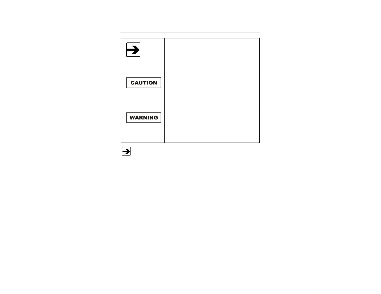
Notes, Cautions, and Warnings
Note: Denotes helpful information intended to
provide tips for better use of the product.
Caution: Denotes a hazard. Failure to follow
instructions could result in minor personal injury
and/or property damage. Included text gives proper
procedures.
Warning: Denotes a hazard. Failure to follow
instructions could result in SEVERE personal injury
and/or property damage. Included text gives proper
procedures.
See the ETS-Lindgren Product Information Bulletin for safety,
regulatory, and other product marking information.
| ix
Page 10
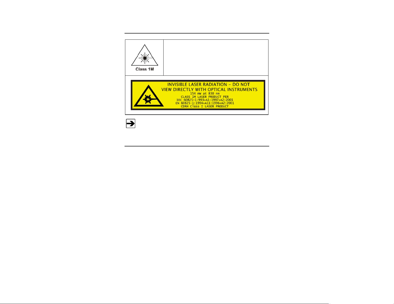
General Safety Considerations
LASER HAZARD. Laser power up to 150 mW at
830 nm may be accessible at the fiber connector of the
laser. However, the laser beam itself is not hazardous
as the interlock ensures that the exposure time will be
less than 30 ms.
See the ETS-Lindgren Product Information Bulletin for safety,
regulatory, and other product marking information.
ETS-Lindgren Product Information Bulletin
See the ETS-Lindgren Product Information Bulletin included with your shipment
for the following:
Warranty information
Safety, regulatory, and other product marking information
Steps to receive your shipment
Steps to return a component for service
ETS-Lindgren calibration service
ETS-Lindgren contact information
x |
Page 11

Laser-Powered
HI-6122
HI-6153
HI-6105
Battery-Operated
HI-6022
HI-6053
HI-6005
ETS-Lindgren may substitute a similar part or new part number with
the same functionality for another part/part number. Contact
ETS-Lindgren for questions about part numbers and ordering parts.
1.0 Introduction
The ETS-Lindgren EMC Field Probes embody the latest innovations in isotropic
sensor design and low-noise, miniaturized electronics. Each probe is a fully
intelligent sensor enabling fast and accurate EMF measurements with
industry-leading performance specifications. Optical coupling to a variety of
readout options makes these probes ideally suited for a wide range of field
monitoring applications.
The EMC field probes include laser-powered (laser) probes and battery-operated
probes. This manual includes operating information and specifications for these
probe models:
Introduction | 11
Page 12
The HI-6100 may be used in
conjunction with both the laser
and battery-operated probes.
HI-6100 Field Monitor
The laser probes and the
HI-6113 Laser Data
Interface together
communicate with
ProbeView™ Laser
software through a USB
port on the computer.
HI-6113 Laser Data Interface
Readout Options
HI-6100 FIELD MONITOR
The HI-6100 Field Monitor accepts inputs from up to any four probes, and
analyzes and displays information on a user-configurable LCD.
For information on using the HI-6100 with ETS-Lindgren probes, see HI-6100
Field Monitor Configuration on page 18.
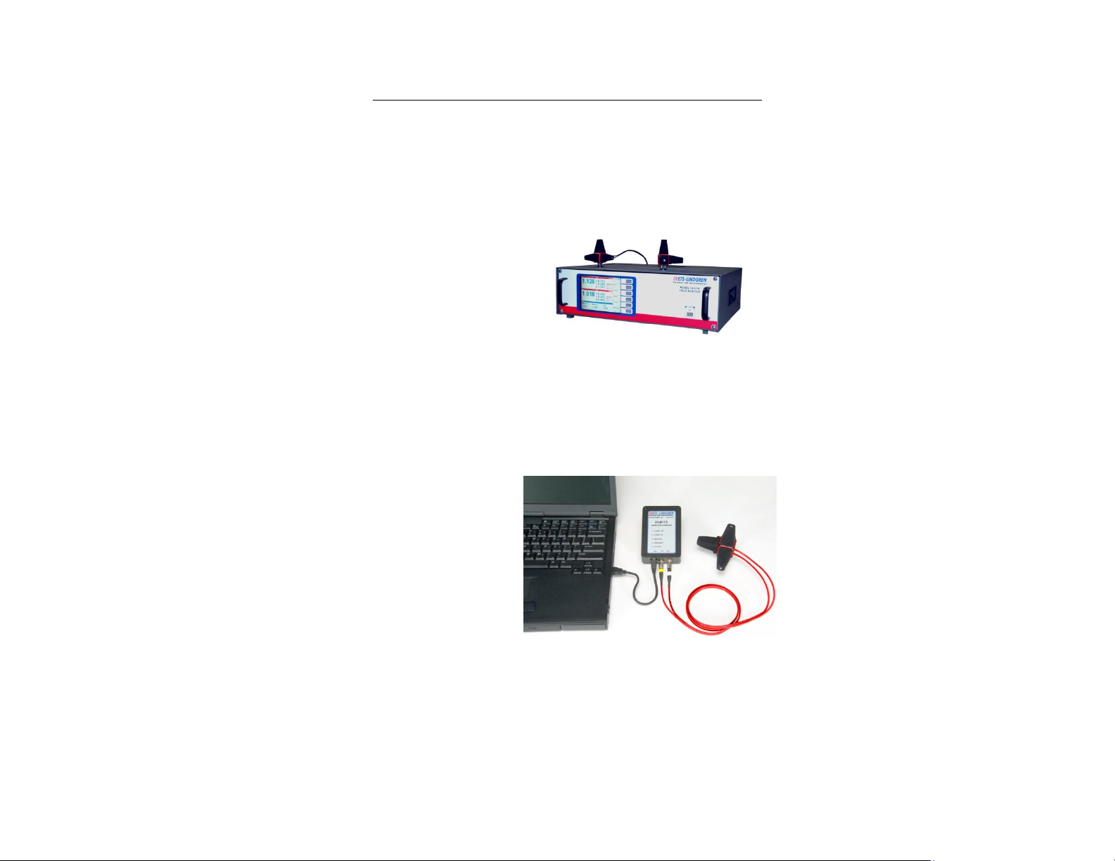
HI-6113 LASER DATA INTERFACE
For information on using the HI-6113 with ETS-Lindgren probes, see HI-6113
Laser Data Interface Configuration on page 19.
12 | Introduction
Page 13
The battery-powered probes use the
HI-4413P Fiber Optic Modem to
communicate with ProbeView II™
software through a serial port on the
computer.
HI-4413P Fiber Optic Modem
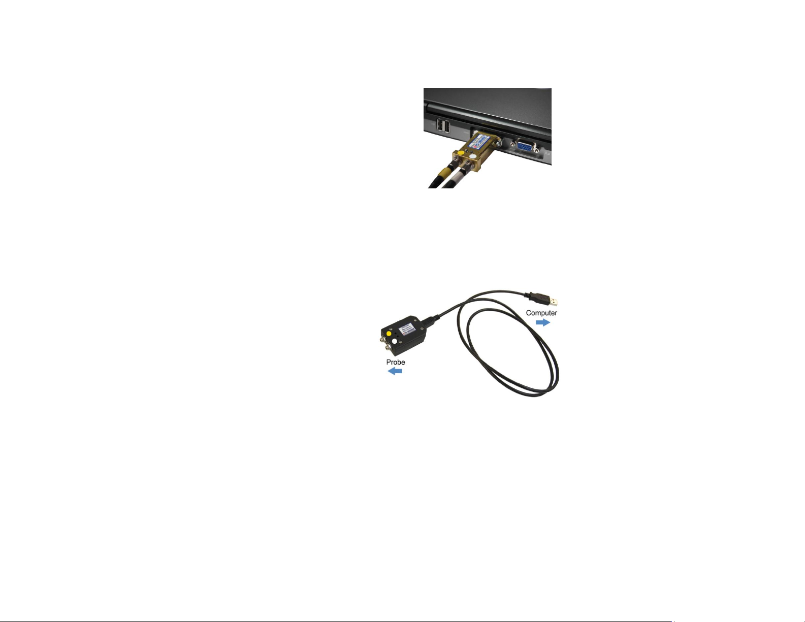
The battery-powered
probes use the
HI-4413USB Fiber Optic to
USB Converter to
communicate with
ProbeView II™ software
through a USB port on the
computer.
HI-4413USB Fiber Optic to USB Converter
HI-4413P FIBER OPTIC MODEM
For information on using the HI-4413P with ETS-Lindgren probes, see
HI-4413P / HI-4413USB Configuration on page 20.
HI-4413USB FIBER OPTIC TO USB CONVERTER
For information on using the HI-4413USB with ETS-Lindgren probes, see
HI-4413P / HI-4413USB Configuration on page 20.
Introduction | 13
Page 14
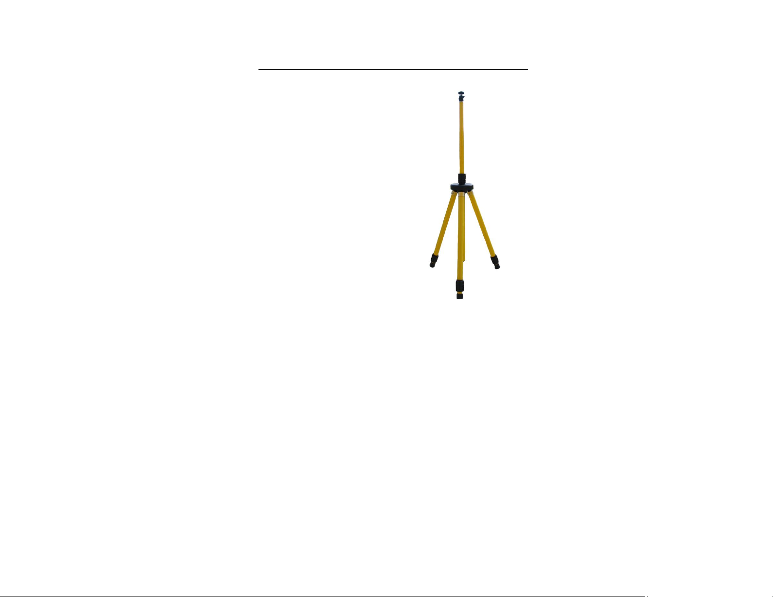
The H-491009 Dielectric Tripod is the
preferred method for mounting field probes
for making unperturbed field
measurements. It provides stable
placement for one probe, and includes a
1/4–20 UNC threaded stud for mounting
any ETS-Lindgren probe with a tripod
mount. It is designed with an adjustable
center post and a rotating mount.
Optional Tripod
14 | Introduction
Page 15
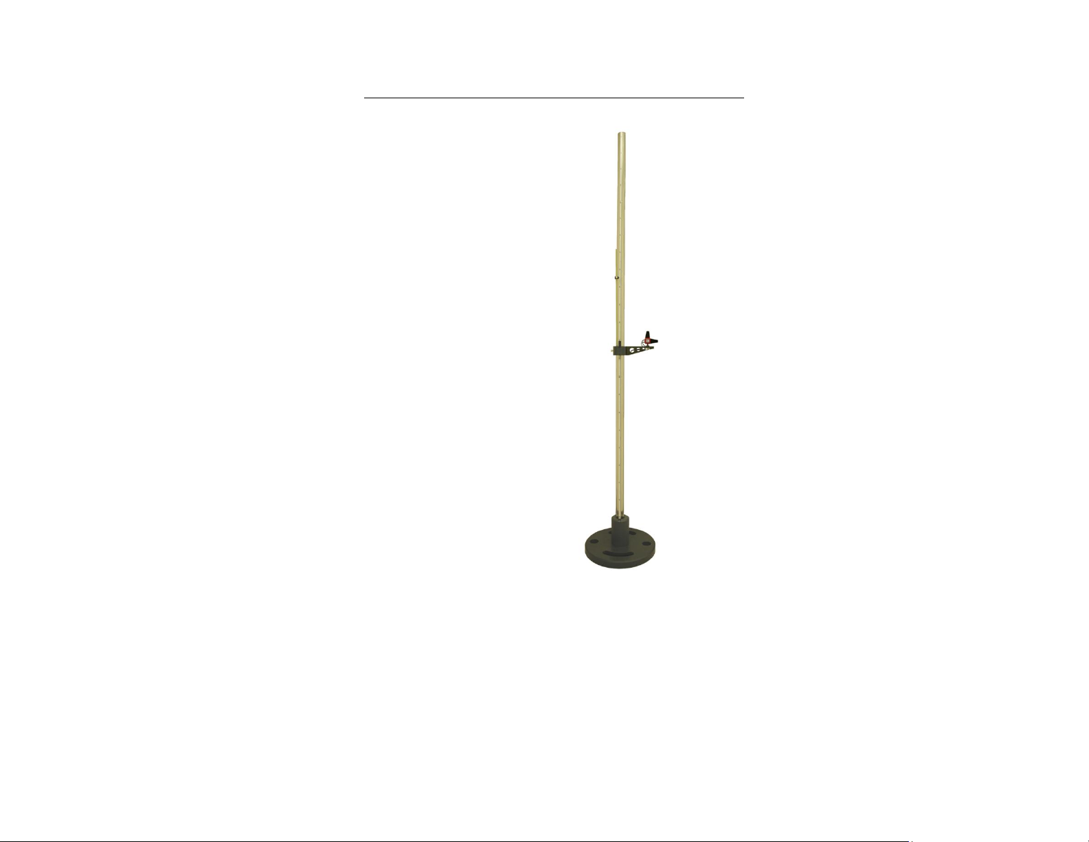
The ETS-Lindgren Probe Stand
may also be used in testing
configurations. The probe stand
supports up to two probes. For
complete information on probe
stand assembly and operation, see
H-491269 Probe Stand on page 73.
Optional Probe Stand
Introduction | 15
Page 16

For information on reducing measurement uncertainties and selecting
the best field probe for your application see the white paper Practical
Considerations for Radiated Immunities Measurement using
ETS-Lindgren EMC Field Probes. This document is located on the
ETS-Lindgren website at: www.ets-lindgren.com/whitepapers.
For complete information on setting up and operating the field monitor,
software, and other devices available for the laser and
battery-operated field probes, please see the documentation provided
with those products.
Field probes are nominally rated for operation within a specific
frequency range, but may also respond to signals above and below
those frequencies. A probe may exhibit response to frequencies below
the lower end of the range, and may also respond to frequencies
above the upper end of the range, though not consistently or
predictably.
Keep all conductive objects away from laser-powered and
battery-operated probes. Conductive objects in the proximity of the
probe can distort the near field and compromise measurement
accuracy. If the application requires measurements from a fixed
position, always mount the probe on a non-metallic platform, using
non-metallic screws.
About Probe Operation
16 | Introduction
Page 17

2.0 Typical Configurations
A variety of configurations are available with the field monitors, probes, and other
devices. Following are typical examples of how the components can be
assembled to accommodate most testing environments.
Typical Configurations | 17
Page 18
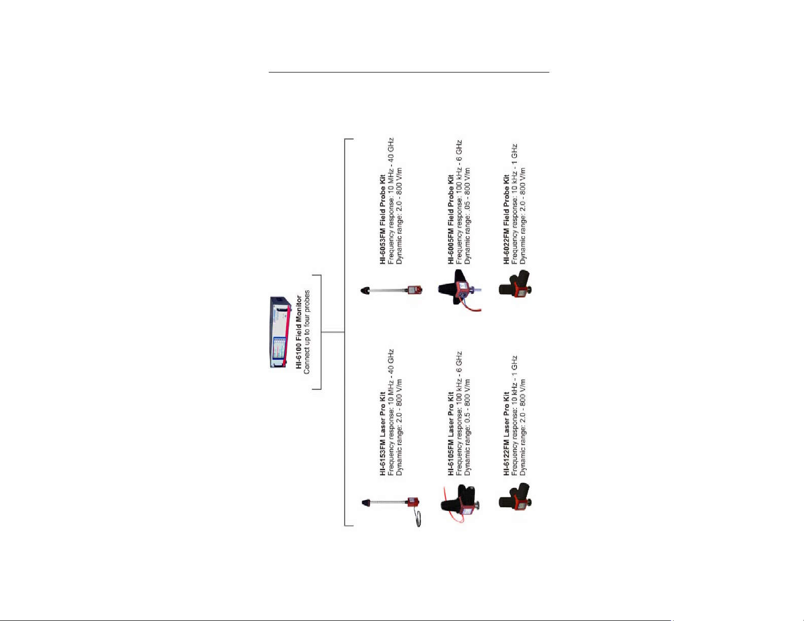
HI-6100 Field Monitor Configuration
The following diagram illustrates the ETS-Lindgren probes that may be used with
the HI-6100 Field Monitor. In the diagram, the FM in HI-6153FM, for example,
refers to Field Monitor Kit. As a kit, the probe includes an interface card.
18 | Typical Configurations
Page 19
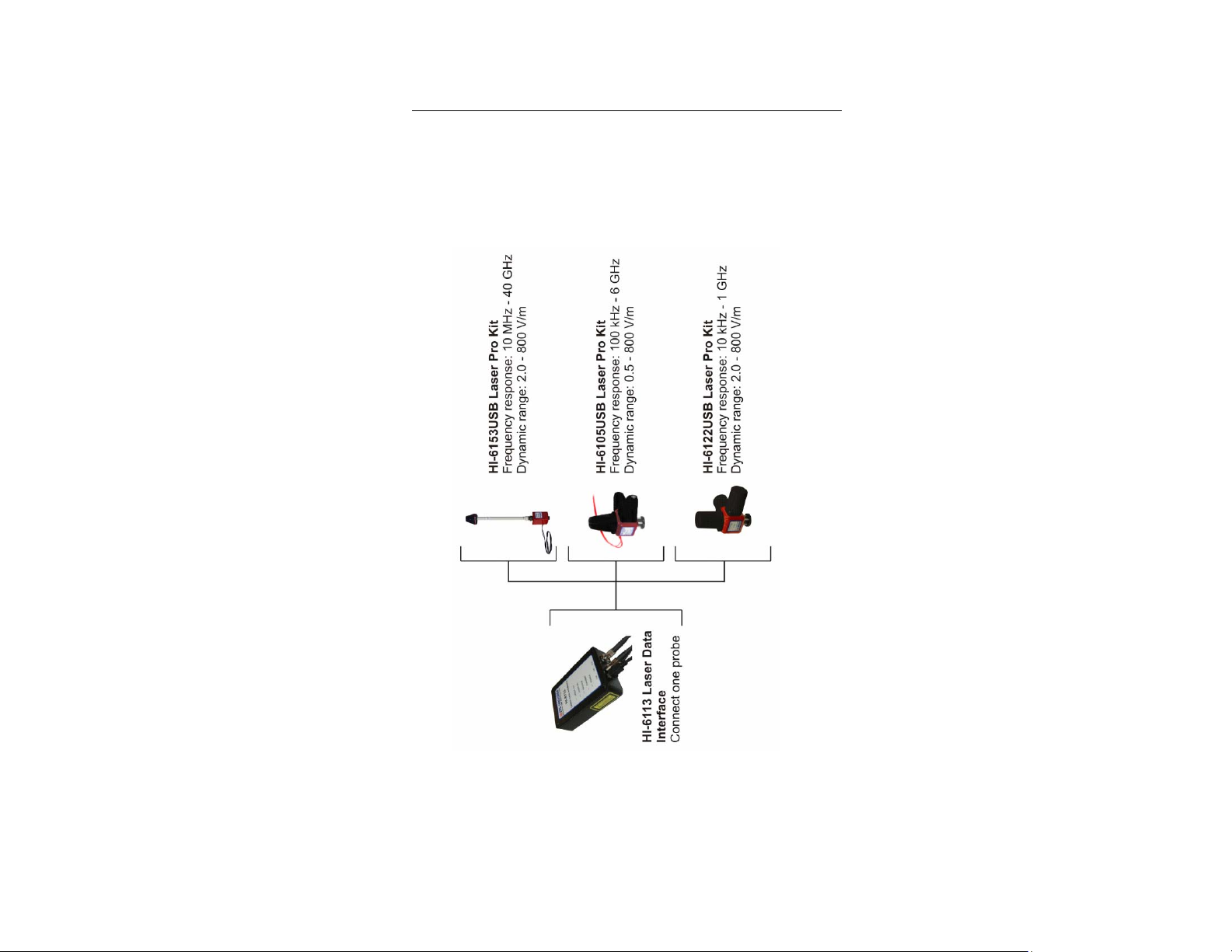
HI-6113 Laser Data Interface Configuration
The following diagram illustrates the ETS-Lindgren probes that may be used with
the HI-6113 Laser Data Interface (LDI). In the diagram, the USB in HI-6153USB,
for example, refers to USB Kit. As a kit, the probe includes all components
required to operate the probe with the HI-6113.
Typical Configurations | 19
Page 20
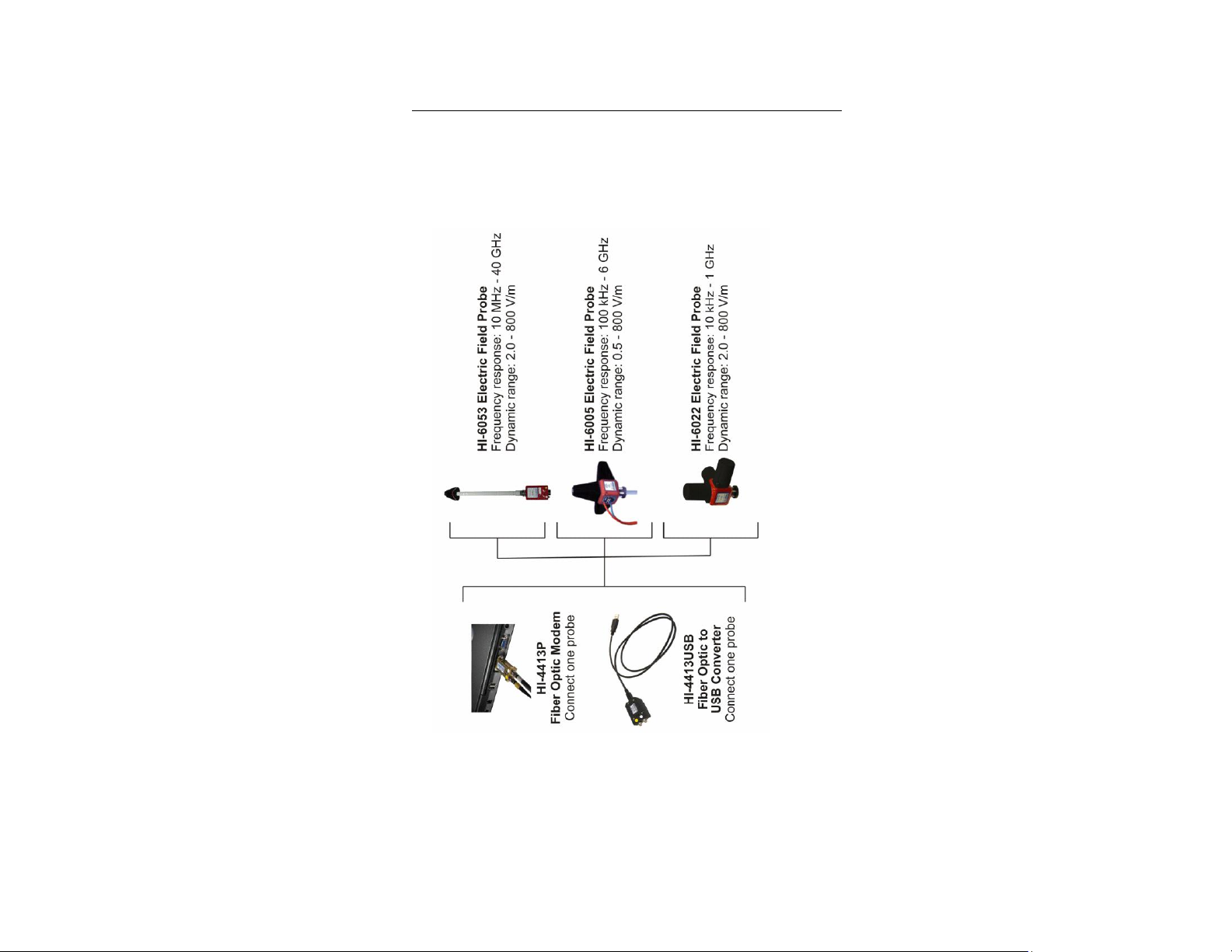
HI-4413P / HI-4413USB Configuration
The following diagram illustrates the ETS-Lindgren probes that may be used with
the HI-4413P Fiber Optic Modem or the HI-4413USB Fiber Optic to USB
Converter.
20 | Typical Configurations
Page 21
Before performing any maintenance,
follow the safety information in the
ETS-Lindgren Product Information
Bulletin included with your shipment.
Maintenance of probes is limited to
external components such as cables or
connectors.
Warranty may be void if the housing is
opened.
If you have any questions concerning
maintenance, contact ETS-Lindgren
Customer Service.
WARRANTY
3.0 Maintenance
If you have one of the following probes, see Probe Shield Care and Replacement
on page 81: HI-6122, HI-6022, HI-6105, or HI-6005 Field Probe.
Annual Calibration
See the Product Information Bulletin included with your shipment for information
on ETS-Lindgren calibration services.
Maintenance | 21
Page 22
Before performing any maintenance, disconnect
the fiber optic cables from the unit and turn off
power.
When disconnecting fiber optic cables, apply the
included dust caps to the ends to maintain their
integrity.
Before connecting fiber optic cables, clean the
connector tips and in-line connectors.
Before attaching in-line connectors, clean them
with moisture-free compressed air.
Failure to perform these tasks may result in
damage to the fiber optic connectors or cables.
Laser Probes and Maintenance of Fiber Optics
The fiber optic connectors and cables used with laser-powered probes can be
damaged from airborne particles, humidity and moisture, oils from the human
body, and debris from the connectors they plug into. Always handle connectors
and cables with care, using the following guidelines.
Upgrade Policies
Periodically, probes are upgraded to enhance functionality. Contact
ETS-Lindgren Customer Service for the upgrade status of your probe.
Service Procedures
For the steps to return a system or system component to ETS-Lindgren for
service, see the Product Information Bulletin included with your shipment.
22 | Maintenance
Page 23

The laser driver in the HI-6100 Field Monitor also incorporates this
safety interlock mechanism, and operates in the same manner.
4.0 Laser-Powered Field Probes
The HI-61XX Series LaserPro™ Field Probe is a laser-powered probe, an
excellent tool for electric field mapping, industrial monitoring, and EMC field
measurements.
The HI-61XX Series probes contain a photo-voltaic converter that provides power
to the probe circuitry when sufficient light power is received by the converter. The
light power is generated by a laser in the HI-6113 Laser Data Interface, and is
transmitted to the converter through an optical fiber in the duplex fiber optic
cable. The probe communicates with the HI-6113 through this fiber optic cable.
Receiving power from the HI-6113 allows for unlimited test times.
The probe system incorporates a safety interlock mechanism that turns off the
laser if the HI-6113 does not receive data from the probe within a specified time
frame. The safety mechanism is intended to prevent injury from the laser if the
HI-6113 issues a command to turn on the laser while the fiber optic cables are
disconnected, improperly connected, cut, or damaged.
The HI-6100 Field Monitor may also be used with the HI-61XX Series for
RFI/EMC testing. For more information on readout options, see page 12.
Laser-Powered Field Probes | 23
Page 24
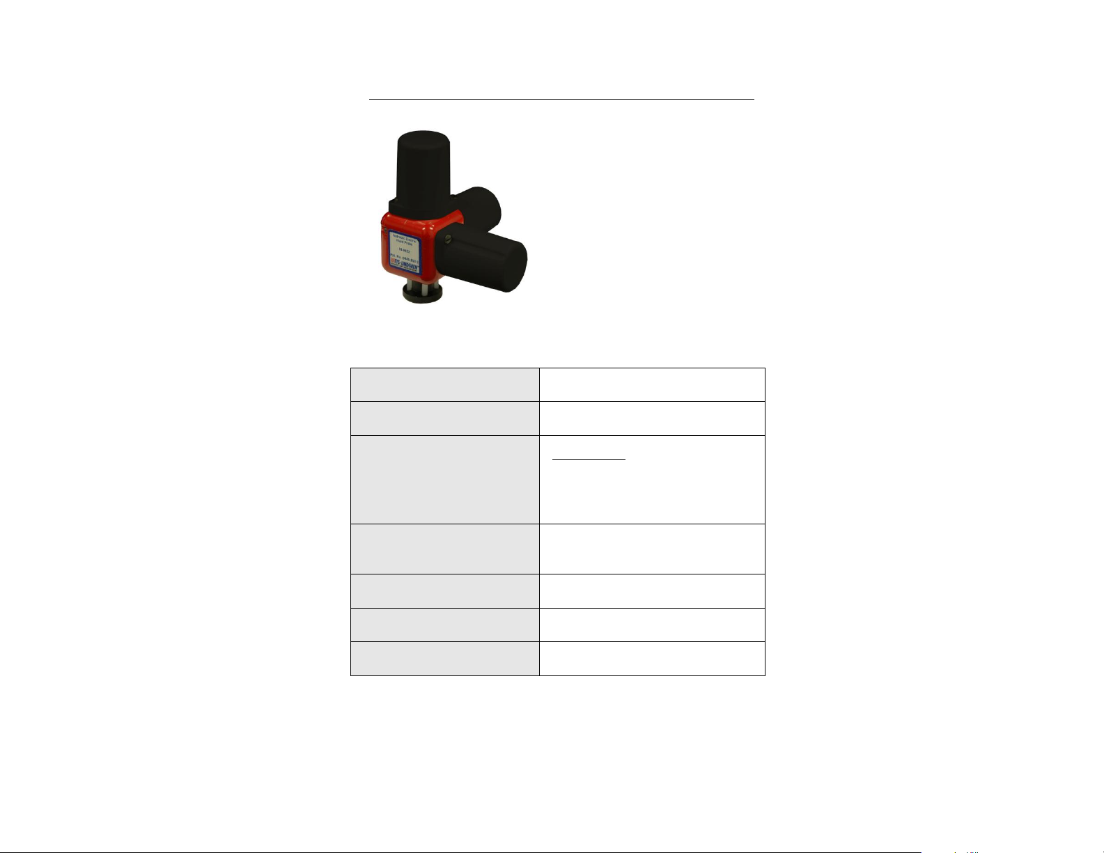
The ETS-Lindgren HI-6122 Field Probe
provides broadband frequency coverage
and wide dynamic range that satisfies the
demands of most test requirements.
The frequency response of the HI-6122 is
10 kHz to 1 GHz, and the dynamic range is
2 to 800 Volts per meter (V/m).
Dynamic Range:
2.0 – 800 Volts per meter (V/m)
Ranges:
Single
Typical Frequency Response:
10 kHz–1 GHz
10 kHz–30 kHz: +0.5 dB, -2.5 dB
30 kHz–1 GHz: ±1 dB
Typical Frequency Response
with Correction:
10 kHz–1 GHz: ±0.9 dB
Linearity:
±0.5 dB @ 27 MHz
Isotropicity:
±0.5 dB @ 400 MHz
Overload Withstand:
> 1,500 V/m CW
HI-6122 Electric Field Probe
HI-6122 SPECIFICATIONS
24 | Laser-Powered Field Probes: HI-6122 Electric Field Probe
Page 25

Physical Interface:
Duplex optical fiber
(62.5 micron multimode)
FC connectors for laser cable,
integral 1-m optical cable
ST connector for transmitter cable,
integral 1-m optical cable
Probe Mount:
1/4–20 UNC tapped hole (internal thread)
Environmental
Operating Temperature:
10°C to 40°C
50°F to 104°F
Humidity:
5% to 95% relative humidity,
non-condensing
Dimensions
Housing:
32 mm x 32 mm x 32 mm
1.26 in x 1.26 in x 1.26 in
Probe Shields:
36 mm (1.42 in)
Weight:
80 g (2.82 oz)
HI-6122 OPERATION
The HI-6122 can be used with the HI-6100 Field Monitor. It can also be
connected to a personal computer using an optional HI-6113 Laser Data
Interface and ProbeView™ Laser software.
The HI-6122 is a true 3-axis probe. When requested, X, Y, Z, and total field data
can be reported.
For a list and description of communication and information transfer protocols,
including command structure, probe commands, and HI-6113 commands, see
Appendix D: Operating Protocols on page 101.
Laser-Powered Field Probes: HI-6122 Electric Field Probe | 25
Page 26
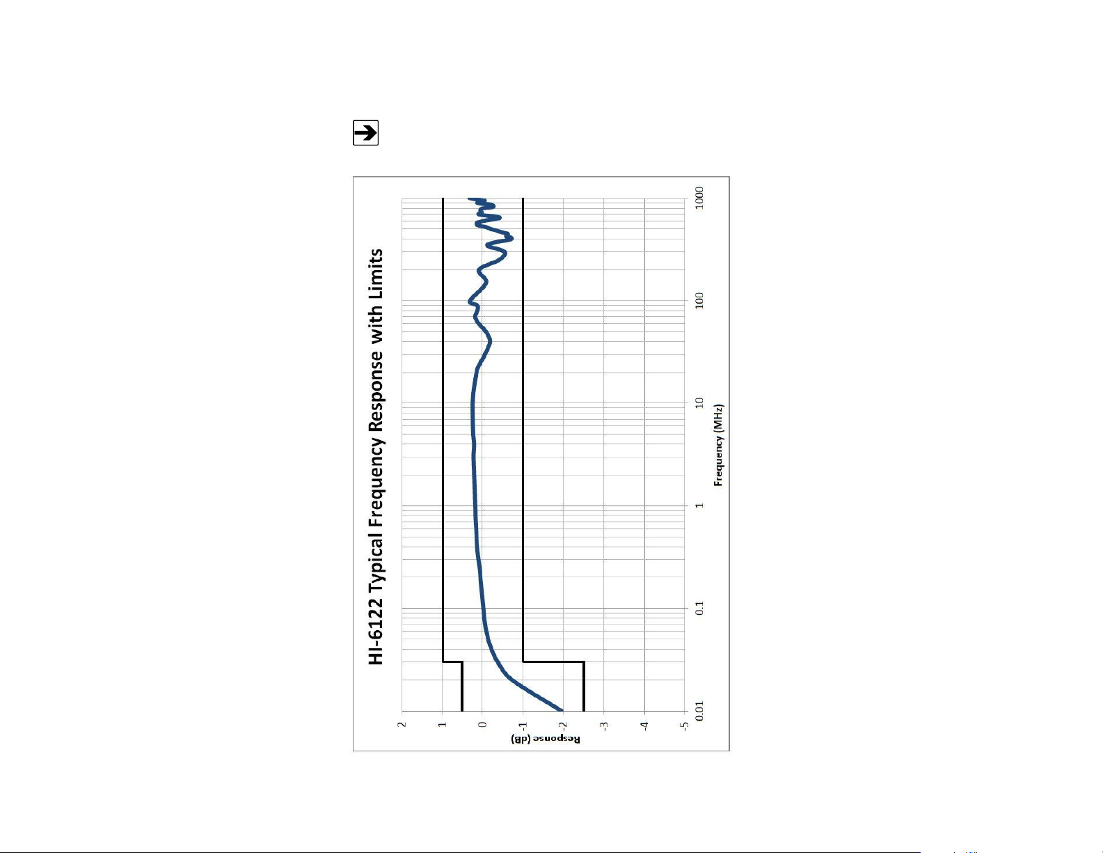
TEM Cell and GTEM! – Field Level 20 V/m
HI-6122 TYPICAL FREQUENCY RESPONSE
26 | Laser-Powered Field Probes: HI-6122 Electric Field Probe
Page 27
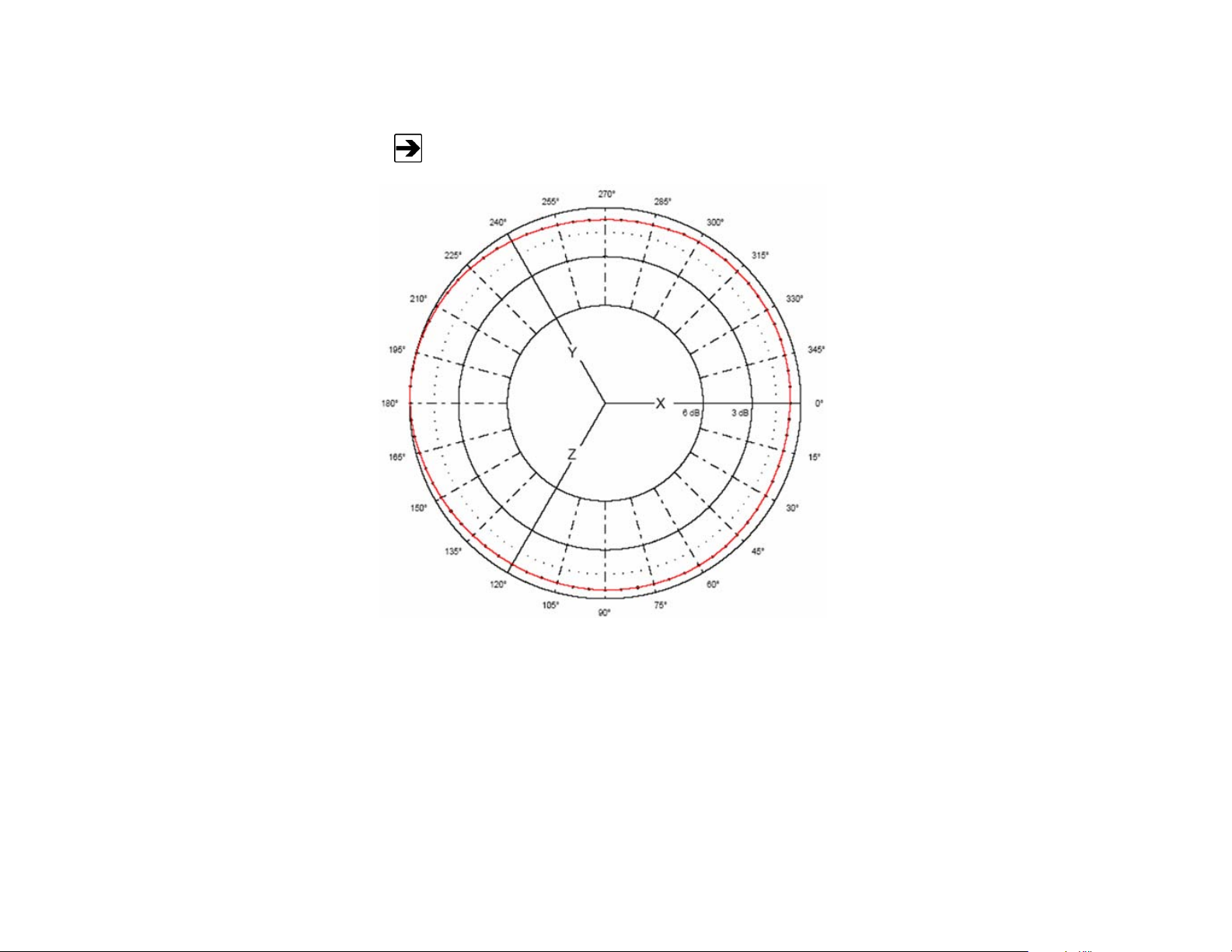
Isotropic response measured in a 20 V/m field at 400 MHz.
HI-6122 TYPICAL ISOTROPIC RESPONSE
Laser-Powered Field Probes: HI-6122 Electric Field Probe | 27
Page 28
Any maintenance or calibration task requires probe disassembly,
which may void your warranty. Only ETS-Lindgren service personnel
should perform these tasks. To avoid problems with your warranty,
contact ETS-Lindgren Customer Service before performing any
maintenance.
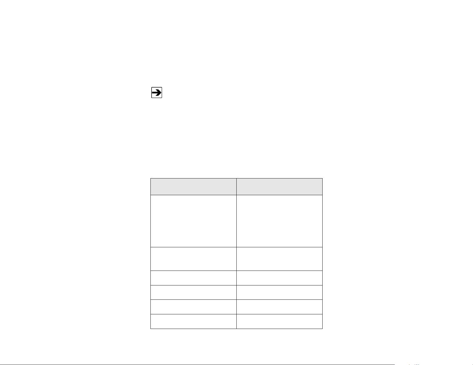
Part Description
Part Number
Probe shield replacement Kit
includes:
Three probe shields (cones)
One each X, Y, and Z label
Six screws
112955
Cable Assembly, Fiber, FC-FC,
ST-ST
H-491263-xx
(xx=length in meters)
FC to FC Inline Connector
H-23861521000
ST to ST Inline Connector
708027
Carrying Case
H-491291
HI-6100 Field Monitor
HI-6100
HI-6122 ADDITIONAL MAINTENANCE
Maintenance of the HI-6122 is limited to external components such as cables,
connectors, and probe shields. For information on fiber optic cable and connector
maintenance, see Laser Probes and Maintenance of Fiber Optics on page 22. To
replace the probe shields, see Probe Shield Care and Replacement on page 81.
For complete information on maintenance and calibration, see Maintenance on
page 21.
HI-6122 ADDITIONAL PARTS
Use the following table to order replacement or optional parts for the HI-6122.
28 | Laser-Powered Field Probes: HI-6122 Electric Field Probe
Page 29

Part Description
Part Number
Laser Data Interface
HI-6113
Tripod, Dielectric
H-491009
Probe Stand
H-491269
Fiber Optic Cleaning System
H-34FO1
Laser System Fiber Optic
Maintenance Kit
112333
Probe Carrier for H-491269
Probe Stand
H-491276
Laser-Powered Field Probes: HI-6122 Electric Field Probe | 29
Page 30
The ETS-Lindgren HI-6153 Field Probe
provides broadband frequency coverage
and wide dynamic range that satisfies the
demands of most test requirements.
The frequency response of the HI-6153 is
10 MHz to 40 GHz, and the dynamic range
is 2 to 800 Volts per meter (V/m).
Dynamic Range:
2.0–800 Volts per meter (V/m)
Ranges:
Single
Typical Frequency Response:
10 MHz–40 GHz
10 MHz–100 MHz: +3 dB, -4 dB
100 MHz–1 GHz: +3 dB, -0.5 dB
1 GHz–18 GHz: +4 dB, -2 dB
18 GHz–40 GHz: +3.5 dB, -4.5 dB
Typical Frequency Response
with Correction:
10 MHz–18 GHz: ± 0.9 dB
18 GHz–40 GHz: ± 1.1 dB
Linearity:
±0.5 dB @ 1 GHz
Isotropicity:
±1.0 dB < 18 GHz
HI-6153 Electric Field Probe
HI-6153 SPECIFICATIONS
30 | Laser-Powered Field Probes: HI-6153 Electric Field Probe
Page 31

Overload Withstand:
1,500 V/m
Physical Interface:
Duplex optical fiber
(62.5 micron multimode)
FC connectors for laser cable,
integral 1-m optical cable
ST connector for transmitter cable,
integral 1-m optical cable
Probe Mount:
1/4–20 UNC tapped hole (internal thread)
Environmental
Operating Temperature:
10°C to 40°C
50°F to 104°F
Humidity:
5% to 95% relative humidity,
non-condensing
Dimensions
Probe Length:
438 mm (17.24 in)
(includes electronics housing)
Probe Diameter:
57 mm (2.24 in)
Weight:
0.36 kg (12.64 oz)
Laser-Powered Field Probes: HI-6153 Electric Field Probe | 31
Page 32

The HI-6153 assembly consists
of a pyramidal casing containing
the sensor, which is mounted on
one end of a shaft. The other
end of the shaft is attached to
an extrusion that houses the
electronics. The sensor and
electronics housing operate and
are calibrated as a unit.
The HI-6153 is a true 3-axis
probe. When requested, X, Y, Z,
and total field data can be
reported.
The HI-6153 can be used with
the HI-6100 Field Monitor. It can
also be connected to a personal
computer using an optional
HI-6113 Laser Data Interface
and ProbeView™ Laser
software.
HI-6153 OPERATION
For a list and description of communication and information transfer protocols,
including command structure, probe commands, and HI-6113 commands, see
Appendix D: Operating Protocols on page 101.
32 | Laser-Powered Field Probes: HI-6153 Electric Field Probe
Page 33

Field Level 20 V/m
HI-6153 TYPICAL FREQUENCY RESPONSE
Laser-Powered Field Probes: HI-6153 Electric Field Probe | 33
Page 34

HI-6153 TYPICAL ISOTROPIC RESPONSE
Typical Isotropic Response in dB at 1 GHz
34 | Laser-Powered Field Probes: HI-6153 Electric Field Probe
Page 35

Typical Isotropic Response in dB at 10 GHz
Laser-Powered Field Probes: HI-6153 Electric Field Probe | 35
Page 36

Typical Isotropic Response in dB at 18 GHz
36 | Laser-Powered Field Probes: HI-6153 Electric Field Probe
Page 37

Any maintenance or calibration task requires probe disassembly, which may
void your warranty. Only ETS-Lindgren service personnel should perform
these tasks. To avoid problems with your warranty, contact ETS-Lindgren
Customer Service before performing any maintenance.
Part Description
Part Number
Cable Assembly, Fiber, FC-FC,
ST-ST
H-491263-xx
(xx=length in meters)
FC to FC Inline Connector
H-23861521000
ST to ST Inline Connector
708027
Carrying Case
H-491291
HI-6100 Field Monitor
HI-6100
HI-6113 Laser Data Interface
HI-6113
H-491009 Tripod, Dielectric,
Field Probe
H-491009
H-491269 Probe Stand
H-491269
Fiber Optic Cleaning System
H-34FO1
HI-6153 ADDITIONAL MAINTENANCE
Maintenance of the HI-6153 is limited to external components such as cables
and connectors. For information on fiber optic cable and connector maintenance,
see Laser Probes and Maintenance of Fiber Optics on page 22.
For complete information on maintenance and calibration, see Maintenance on
page 21.
HI-6153 ADDITIONAL PARTS
Use the following table to order replacement or optional parts for the HI-6153.
Laser-Powered Field Probes: HI-6153 Electric Field Probe | 37
Page 38

Part Description
Part Number
Laser System Fiber Optic
Maintenance Kit
112333
Probe Carrier for H-491269
Probe Stand
H-491276
38 | Laser-Powered Field Probes: HI-6153 Electric Field Probe
Page 39

The ETS-Lindgren HI-6105 Electric
Field Probe is a fully intelligent sensor
enabling fast and accurate
EMF measurements with industry-
leading performance specifications.
Optical coupling to a variety of readout
options makes this probe ideally suited
for a wide range of field monitoring
applications.
Dynamic Range:
0.5–800 Volts per meter (V/m)
Single Range (64 dB)
Typical Frequency Response:
100 kHz–6 GHz
500 kHz–2 GHz: +1 dB, -2.5 dB
2 GHz–5.5 GHz: +3.5 dB, -4 dB
5.5 GHz–6 GHz: +2 dB, -6 dB
Typical Frequency Response
with Correction:
100 kHz–6 GHz: ±0.9 dB
Linearity:
±0.5 dB @ 27 MHz
Isotropicity:
±0.5 dB @ 400 MHz
Overload Withstand:
1,500 V/m
HI-6105 Electric Field Probe
HI-6105 SPECIFICATIONS
Laser-Powered Field Probes: HI-6105 Electric Field Probe | 39
Page 40

Physical Interface:
Duplex optical fiber
(62.5 micron multimode)
FC connectors for laser cable,
integral 1-m optical cable
ST connector for transmitter cable,
integral 1-m optical cable
Probe Mount:
1/4–20 UNC (internal thread)
Dimensions
Housing:
32 mm x 32 mm x 32 mm
1.26 in x 1.26 in x 1.26 in
Probe Shields:
43 mm (1.69 in)
Weight:
0.08 kg (2.6 oz.)
Environmental
Operating Temperature:
10°C to 40°C
50°F to 104°F
Humidity:
5% to 95% relative humidity,
non-condensing
HI-6105 OPERATION
The HI-6105 can be used with the HI-6100 Field Monitor. It can also be
connected to a personal computer using an optional HI-6113 Laser Data
Interface (LDI) and ProbeView™ Laser software.
For a list and description of communication and information transfer protocols,
including command structure, probe commands, and HI-6113 commands, see
Appendix D: Operating Protocols on page 101.
40 | Laser-Powered Field Probes: HI-6105 Electric Field Probe
Page 41

Anechoic Room and TEM Cell – Field Level 20 V/m
HI-6105 TYPICAL FREQUENCY RESPONSE
Laser-Powered Field Probes: HI-6105 Electric Field Probe | 41
Page 42

Actual data taken at 400 MHz, field level 20 V/m, maximum variation
0.54 dB.
HI-6105 TYPICAL ISOTROPIC RESPONSE
42 | Laser-Powered Field Probes: HI-6105 Electric Field Probe
Page 43

Any maintenance or calibration task requires probe disassembly, which may
void your warranty. Only ETS-Lindgren service personnel should perform
these tasks. To avoid problems with your warranty, contact ETS-Lindgren
Customer Service before performing any maintenance.
Part Description
Part Number
Probe shield replacement Kit
includes:
Three probe shields (cones)
One each X, Y, and Z label
Six screws
H-491237
Cable Assembly, Fiber, FC-FC,
ST-ST
H-491263-xx
(xx=length in meters)
FC to FC Inline Connector
H-23861521000
ST to ST Inline Connector
708027
HI-6105 ADDITIONAL MAINTENANCE
Maintenance of the HI-6105 is limited to external components such as cables,
connectors, and probe shields. For information on fiber optic cable and connector
maintenance, see Laser Probes and Maintenance of Fiber Optics on page 22. To
replace the probe shields, see Probe Shield Care and Replacement on page 81.
For complete information on maintenance and calibration, see Maintenance on
page 21.
HI-6105 ADDITIONAL PARTS
Use the following tables to order replacement or optional parts for the HI-6105.
Laser-Powered Field Probes: HI-6105 Electric Field Probe | 43
Page 44

Part Description
Part Number
Tripod, Dielectric
H-491009
HI-6100 Field Monitor
HI-6100
Laser Data Interface
HI-6113
Probe Stand
H-491269
Fiber Optic Cleaning System
H-34FO1
Laser System Fiber Optic
Maintenance Kit
112333
Probe Carrier for H-491269
Probe Stand
H-491276
44 | Laser-Powered Field Probes: HI-6105 Electric Field Probe
Page 45

Before using your battery-operated probe, read the following:
HI-6053 Field Probe: Appendix B: Series H-491198-01 Battery
Charger on page 85.
HI-6022 and HI-6005 Field Probe: Appendix C: Series H-491198-48
Battery Charger on page 93.
To calibrate the probe prior to shipment, ETS-Lindgren also charges
the internal battery at the factory. Every effort is made to make sure
that the probe arrives ready to use, but you should verify the condition
of the battery prior to making any measurements.
5.0 Battery-Operated Field Probes
The HI-60XX Series Field Probe is a battery-operated probe that utilizes
three orthogonal sensors to provide an isotropic reading of the electric field.
When requested, X, Y, Z, and total field data can be reported, making the
HI-60XX Series true 3-axis probes.
The HI-60XX Series uses either the HI-4413P Fiber Optic Modem or the
HI-4413USB Fiber Optic to USB Converter to communicate with ProbeView II™
software through a port on the computer. The HI-6100 Field Monitor may also be
used with the HI-60XX Series. For more information on readout options, see
page 12.
Battery-Operated Field Probes | 45
Page 46

The ETS-Lindgren HI-6022 Field Probe
provides broadband frequency coverage
and wide dynamic range that satisfies the
demands of most test requirements.
The frequency response of the HI-6022 is
10 kHz to 1 GHz, and the dynamic range is
2 to 800 Volts per meter (V/m).
Dynamic Range:
2.0–800 Volts per meter (V/m)
Ranges:
Single
Typical Frequency Response:
10 kHz–1 GHz
10 kHz–30 kHz: +0.5 dB, -2.5 dB
30 kHz–1 GHz: ±1 dB
Typical Frequency Response
with Correction:
10 kHz–1 GHz: ±0.9 dB
Linearity:
±0.5 dB @ 27 MHz
Isotropicity:
±0.5 dB @ 400 MHz
Overload Withstand:
> 1,500 V/m CW
Fiber Optic Cable Connector:
Standard FSMA
Probe Mount:
1/4–20 UNC tapped hole (internal thread)
HI-6022 Field Probe
HI-6022 SPECIFICATIONS
46 | Battery-Operated Field Probes: HI-6022 Field Probe
Page 47

Battery:
Rechargeable Nickel-Metal Hydride
(NiMH)
Battery Life:
Up to 8 hours
Battery Charger:
100–240 VAC universal input
3-hour charge from full depletion
Environmental
Operating Temperature:
10°C to 40°C
50°F to 104°F
Humidity:
5% to 95% relative humidity,
non-condensing
Dimensions
Housing:
32 mm x 32 mm x 32 mm
1.26 in x 1.26 in x 1.26 in
Probe Shields:
36 mm (1.42 in)
Weight:
80 g (2.82 oz)
HI-6022 OPERATION
The HI-6022 can be used with the HI-6100 Field Monitor. It can also be
connected to a personal computer using an optional HI-4413P Fiber Optic
Modem or HI-4413USB Fiber Optic to USB Converter and
ProbeView II™ software.
The HI-6022 is a true 3-axis probe. When requested, X, Y, Z, and total field data
can be reported.
For a list and description of communication and information transfer protocols,
including command structure and probe commands, see Appendix D: Operating
Protocols on page 101.
Battery-Operated Field Probes: HI-6022 Field Probe | 47
Page 48

HI-6022 POWER SWITCH
The power switch activates and deactivates the HI-6022:
ON (I)—When the power switch is in the I position, an internal 4.8 VDC
Nickel-Metal Hydride (NiMH) battery provides power to the probe, and
the power indicator LED blinks.
OFF (0)—When the power switch is in the O position, the probe is
inactive. To prolong battery life, set the switch to OFF when the probe
is not in use.
48 | Battery-Operated Field Probes: HI-6022 Field Probe
Page 49

TEM Cell and GTEM! – Field Level 20 V/m
HI-6022 TYPICAL FREQUENCY RESPONSE
Battery-Operated Field Probes: HI-6022 Field Probe | 49
Page 50

Isotropic response measured in a 20 V/m field at 400 MHz.
HI-6022 TYPICAL ISOTROPIC RESPONSE
50 | Battery-Operated Field Probes: HI-6022 Field Probe
Page 51

Any maintenance or calibration task requires probe disassembly,
which may void your warranty. Only ETS-Lindgren service personnel
should perform these tasks. To avoid problems with your warranty,
contact ETS-Lindgren Customer Service before performing any
maintenance.
Optional Part Description
Part Number
Probe shield replacement Kit
includes:
Three probe shields (cones)
One each X, Y, and Z label
Six screws
112955
Cable, Fiber Optic, Glass
H-491106-xx
(xx=length in meters)
Connector Set, two required
(Bulkhead Feedthrough)
H-231205000
Fiber Optic Modem, RS-232
Interface
HI-4413P
Fiber Optic to USB Converter, USB
Interface
HI-4413USB
HI-6022 ADDITIONAL MAINTENANCE
Maintenance of the HI-6022 is limited to external components such as cables,
connectors, and probe shields. To replace the probe shields, see Probe Shield
Care and Replacement on page 81.
For complete information on maintenance and calibration, see Maintenance on
page 21.
HI-6022 ADDITIONAL PARTS
Use the following table to order replacement or optional parts for the HI-6022.
Battery-Operated Field Probes: HI-6022 Field Probe | 51
Page 52

Optional Part Description
Part Number
Battery Charger
H-491198-48
Carrying Case
H-491291
Tripod, Dielectric
H-491009
HI-6100 Field Monitor
HI-6100
Probe Stand
H-491269
Probe Carrier for H-491269
Probe Stand
H-491276
52 | Battery-Operated Field Probes: HI-6022 Field Probe
Page 53

The ETS-Lindgren HI-6053 Field Probe provides broadband
frequency coverage and wide dynamic range that satisfies the
demands of most test requirements.
The frequency response of the HI-6053 is 10 MHz to 40 GHz,
and the dynamic range is 2 to 800 Volts per meter (V/m).
Dynamic Range:
2.0–800 Volts per meter (V/m)
Ranges:
Single
Typical Frequency Response:
10 MHz–40 GHz
10 MHz–100 MHz: +3 dB, -4 dB
100 MHz–1 GHz: +3 dB, -0.5 dB
1 GHz–18 GHz: +4 dB, -2 dB
18 GHz–40 GHz: +3.5 dB, -4.5 dB
Typical Frequency Response
with Correction:
10 MHz–18 GHz: ±0.9 dB
18 GHz–40 GHz: ±1.1 dB
Linearity:
±0.5 dB @ 1 GHz
Isotropicity:
±1.0 dB < 18 GHz
HI-6053 Field Probe
HI-6053 SPECIFICATIONS
Battery-Operated Field Probes: HI-6053 Field Probe | 53
Page 54

Overload Withstand:
1,500 V/m
Fiber Optic Cable Connector:
Standard FSMA
Probe Mount:
1/4–20 UNC tapped hole (internal thread)
Battery:
Four AAA batteries, rechargeable
Nickel-Metal Hydride (NiMH)
Battery Charger:
100–240 VAC
Approximately three hours
Battery Life:
> 30 hours continuous (at full charge)
Environmental
Operating Temperature:
10°C to 40°C
50°F to 104°F
Humidity:
5% to 95% relative humidity,
non-condensing
Dimensions
Probe Length:
438 mm (17.24 in)
(includes electronics housing)
Probe Diameter:
57 mm (2.24 in)
Weight:
0.36 kg (12.64 oz)
54 | Battery-Operated Field Probes: HI-6053 Field Probe
Page 55

The HI-6053 assembly consists of a
pyramidal casing containing the
sensor, which is mounted on one
end of a shaft. The other end of the
shaft is attached to an extrusion
that houses the electronics. The
sensor and electronics housing
operate and are calibrated as a
unit.
The HI-6053 is a true 3-axis probe.
When requested, X, Y, Z, and total
field data can be reported.
The HI-6053 can be used with the
HI-6100 Field Monitor. It can also
be connected to a personal
computer using an optional
HI-4413P Fiber Optic Modem or
HI-4413USB Fiber Optic to USB
Converter and ProbeView II™
software.
HI-6053 OPERATION
For a list and description of communication and information transfer protocols,
including command structure and probe commands, see Appendix D: Operating
Protocols on page 101.
Battery-Operated Field Probes: HI-6053 Field Probe | 55
Page 56

HI-6053 POWER SWITCH
The power button that activates and deactivates the HI-6053 is located on the
bottom of the electronic housing. A green indicator light in the power button
flashes when the probe is on.
On—To turn the HI-6053 on, push in the power button, and then
release. The power button flashes a green indicator light when the
probe is on, and four AAA Nickel-Metal Hydride (NiMH) batteries
supply power.
Off—To turn the HI-6053 off, push in the power button, and then
release. The green indicator light stops flashing, indicating the probe is
off. When not in use, turn the probe off to prolong battery life.
56 | Battery-Operated Field Probes: HI-6053 Field Probe
Page 57

HI-6053 CONTROLS
Two fiber optic connectors and a battery charger connector are mounted on the
HI-6053 housing.
Battery-Operated Field Probes: HI-6053 Field Probe | 57
Page 58

Field Level 20 V/m
HI-6053 TYPICAL FREQUENCY RESPONSE
58 | Battery-Operated Field Probes: HI-6053 Field Probe
Page 59

HI-6053 TYPICAL ISOTROPIC RESPONSE
Typical Isotropic Response in dB at 1 GHz
Battery-Operated Field Probes: HI-6053 Field Probe | 59
Page 60

Typical Isotropic Response in dB at 10 GHz
60 | Battery-Operated Field Probes: HI-6053 Field Probe
Page 61

Typical Isotropic Response in dB at 18 GHz
Battery-Operated Field Probes: HI-6053 Field Probe | 61
Page 62

Any other maintenance or calibration task requires probe disassembly, which
may void your warranty. Only ETS-Lindgren service personnel should
perform these tasks. To avoid problems with your warranty, contact
ETS-Lindgren Customer Service before performing any maintenance.
If you are not qualified to perform this procedure, please consult
ETS-Lindgren Customer Service. ETS-Lindgren is not responsible for
damage to the probe as a result of replacing the batteries.
See the Product Information Bulletin included with your shipment for
information on ETS-Lindgren calibration services.
HI-6053 ADDITIONAL MAINTENANCE
Maintenance of the HI-6053 is limited to external components such as cables or
connectors, and replacing the batteries. For complete information on replacing
the batteries, see the next section, HI-6053 Battery Replacement.
For complete information on maintenance and calibration, see Maintenance on
page 21.
HI-6053 BATTERY REPLACEMENT
During the annual calibration of your HI-6053 at the ETS-Lindgren factory, the
batteries are tested to verify continued operability. If required, the batteries are
replaced at that time. It is rare that you should need to replace the batteries
between calibration checks, but in that event, follow these steps.
1. Turn the HI-6053 off. Verify that the green indicator light is not flashing.
2. Carefully disconnect the fiber optic cables from the Transmit and
3. Remove the two nuts; one on each fiber optic connector.
4. Remove the four screws from the bottom of the electronics housing.
5. Lift the bottom away from the housing. Wires from the power button
62 | Battery-Operated Field Probes: HI-6053 Field Probe
Receive connectors.
are connected to the internal circuitry, so carefully turn the bottom over
and place it to the side, avoiding placing stress on the wires.
Page 63

6. A single connector attaches the two boards together. Withdraw the two
boards from the housing at the same time. The boards should easily
slide out of the tracks.
7. Detach the two boards by carefully separating them at the connector,
avoiding damage to the pins.
8. Replace the four AAA rechargeable NiMH batteries, orienting the
+/- ends as indicated.
Battery-Operated Field Probes: HI-6053 Field Probe | 63
Page 64

Recycle the used batteries, or dispose of them safely and properly.
Many cities collect used batteries for recycling or disposal. You may
contact your local waste disposal agency for information on battery
recycling and disposal.
Optional Part Description
Part Number
Cable, Fiber Optic, Glass
H-491106-xx
(xx=length in meters)
Connector Set, two required
(Bulkhead Feedthrough)
H-231205000
Fiber Optic / RS232 Interface
HI-4413P
Fiber Optic to USB Converter, USB
Interface
HI-4413USB
Battery Charger
H-491198-01
Carrying Case
H-491291
Tripod, Dielectric
H-491009
9. Reattach the two boards at the connector.
10. Slide the two boards into the correct tracks inside the housing, and
carefully push them until they are completely recessed.
11. Replace the bottom of the housing, avoiding damage to the power
button wires.
12. Replace and tighten the four screws into the bottom of the housing.
13. Replace the two nuts removed in step 3; one on each fiber optic
connector.
HI-6053 ADDITIONAL PARTS
Use the following table to order replacement or optional parts for the HI-6053.
64 | Battery-Operated Field Probes: HI-6053 Field Probe
Page 65

Optional Part Description
Part Number
HI-6100 Field Monitor
HI-6100
Probe Stand
H-491269
Probe Carrier for H-491269
Probe Stand
H-491276
Battery-Operated Field Probes: HI-6053 Field Probe | 65
Page 66

The ETS-Lindgren HI-6005 Field Probe
is a fully intelligent sensor enabling fast
and accurate EMF measurements with
industry-leading performance
specifications. Optical coupling to a
variety of readout options makes this
probe ideally suited for a wide range of
field monitoring applications.
Dynamic Range:
0.5–800 Volts per meter (V/m)
Single Range (64 dB)
Typical Frequency Response:
100 kHz–6 GHz
500 kHz–2 GHz: +1 dB, -2.5 dB
2 GHz–5.5 GHz: +3.5 dB, -4 dB
5.5 GHz–6 GHz: +2 dB, -6 dB
Typical Frequency Response
with Correction:
100 kHz–6 GHz: ±0.9 dB
Linearity:
±0.5 dB @ 27 MHz
Isotropicity:
±0.5 dB @ 400 MHz
Overload Withstand:
1,500 V/m maximum
Continuous field
Fiber Optic Cable Connectors:
Standard FSMA
HI-6005 Field Probe
HI-6005 SPECIFICATIONS
66 | Battery-Operated Field Probes: HI-6005 Field Probe
Page 67

Probe Mount:
1/4–20 UNC (internal thread)
Battery:
Rechargeable Nickel-Metal Hydride
(NiMH)
Battery Charger:
100–240 VAC
Approximately three hours
Dimensions
Housing:
32 mm x 32 mm x 32 mm
1.26 in x 1.26 in x 1.26 in
Probe Shields:
43 mm (1.69 in)
Weight:
0.08 kg (2.6 oz)
Environmental
Operating Temperature:
10°C to 40°C
50°F to 104°F
Humidity:
5% to 95% relative humidity,
non-condensing
HI-6005 OPERATION
The HI-6005 can be used with the HI-6100 Field Monitor. It can also be
connected to a personal computer using an optional HI-4413P Fiber Optic
Modem or HI-4413USB Fiber Optic to USB Converter and
ProbeView II™ software.
The HI-6005 is a true 3-axis probe. When requested, X, Y, Z, and total field data
can be reported.
For a list and description of communication and information transfer protocols,
including command structure and probe commands, see Appendix D: Operating
Protocols on page 101.
Battery-Operated Field Probes: HI-6005 Field Probe | 67
Page 68

HI-6005 POWER SWITCH
The power switch activates and deactivates the HI-6005:
ON (I)—When the power switch is in the I position, an internal 4.8 VDC
Nickel-Metal Hydride (NiMH) battery provides power to the probe, and
the power indicator LED blinks.
OFF (0) —When the power switch is in the O position, the probe is
inactive. When not in use, turn the probe off to prolong battery life.
68 | Battery-Operated Field Probes: HI-6005 Field Probe
Page 69

Anechoic Room and TEM Cell – Field Level 20 V/m
HI-6005 TYPICAL FREQUENCY RESPONSE
Battery-Operated Field Probes: HI-6005 Field Probe | 69
Page 70

Actual data taken at 400 MHz, field level 20 V/m, maximum variation
0.54 dB.
HI-6005 TYPICAL ISOTROPIC RESPONSE
70 | Battery-Operated Field Probes: HI-6005 Field Probe
Page 71

Any maintenance or calibration task requires probe disassembly, which may
void your warranty. Only ETS-Lindgren service personnel should perform
these tasks. To avoid problems with your warranty, contact ETS-Lindgren
Customer Service before performing any maintenance.
Part Description
Part Number
Cone replacement Kit includes:
Three cones
One each X, Y, and Z label
Six screws
H-651016
Battery Charger
H-491198-48
Carrying Case
H-491207
Cable, Fiber Optic, Glass
H-491106-xx
(xx=length in meters)
Connector Set, two
(Bulkhead Feedthrough)
H-231205000
Fiber Optic/RS232 Interface
HI-4413P
Fiber Optic to USB Converter, USB
Interface
HI-4413USB
HI-6005 ADDITIONAL MAINTENANCE
Maintenance of the HI-6005 is limited to external components such as cables,
connectors, and probe shields. To replace the probe shields, see Probe Shield
Care and Replacement on page 81.
For complete information on maintenance and calibration, see Maintenance on
page 21.
HI-6005 ADDITIONAL PARTS
Use the following tables to order replacement or optional parts for the HI-6005.
Battery-Operated Field Probes: HI-6005 Field Probe | 71
Page 72

Part Description
Part Number
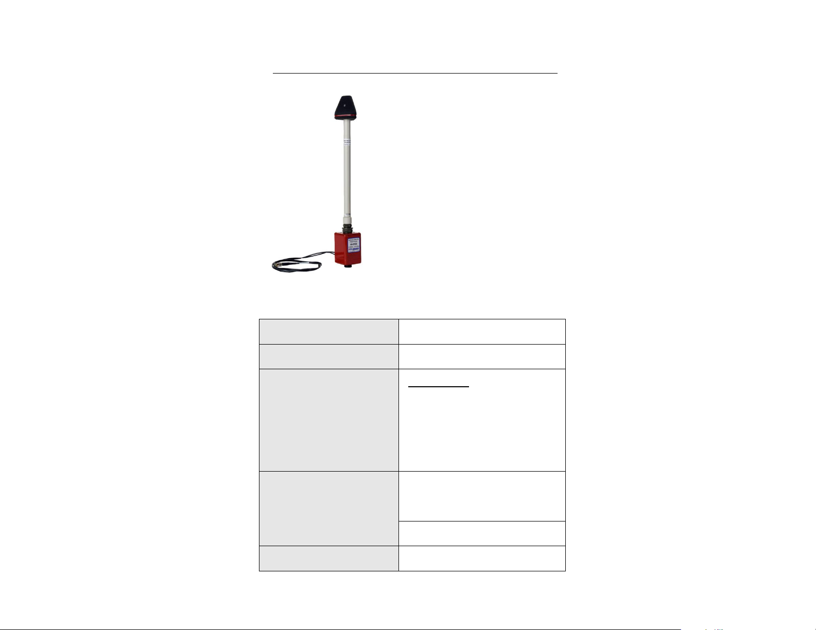
Tripod, Dielectric
H-491009
HI-6100 Field Monitor
HI-6100
Probe Stand
H-491269
Probe Carrier for H-491269
Probe Stand
H-491276
72 | Battery-Operated Field Probes: HI-6005 Field Probe
Page 73

The ETS-Lindgren Probe Stand is
designed for EMC testing in anechoic
chambers and shielded enclosures. The
probe stand provides stable placement for
up to two probes.
PROBE STAND DIMENSIONS
Base Plate and
Tube Height:
2438 mm
96 in
Tube Height:
2248 mm
88.50 in
Base Width:
406 mm
16 in
Tube Width:
51 mm
2 in
6.0 H-491269 Probe Stand
H-491269 Probe Stand | 73
Page 74

In addition to these
parts, the probe stand
includes the following
assembly hardware:
Locking knobs (4)
1/4–20 x 3/4-inch
thumbscrews (2)
10–32 x 5/8-inch
set screw
8–32 x 3/8-inch
thumbscrew
Probe Stand Assembly
PARTS TO ASSEMBLE
74 | H-491269 Probe Stand
Page 75

For accurate measurements, make sure to completely insert the
probe stand tube into the base plate. When fully inserted, the
bottom of the tube should rest evenly on the floor or surface.
On the bottom of the base plate are rubber feet. Make sure all feet
rest evenly on the floor or surface.
Incorrect tube placement or an uneven base can cause inaccurate
measurements.
STEPS TO ASSEMBLE
1. Insert the probe stand tube into the base plate.
H-491269 Probe Stand | 75
Page 76

Testing can be performed using two probes simultaneously. If you
ordered an optional second probe carrier, attach the additional probe
carrier by repeating step 3.
2. To stabilize the tube, insert and tighten the two locking knobs into their
locations.
3. Attach the probe carrier to the tube. Insert one 1/4–20 x 3/4
thumbscrew into the end closer to the tube, and a second one at the
center of the tube. Tighten the thumbscrews.
76 | H-491269 Probe Stand
Page 77

4. Attach the scale pointer to the tube with the 10–32 x 5/8 set screw.
5. Attach the support rod to the tube with the 8–32 x 3/8 thumbscrew.
H-491269 Probe Stand | 77
Page 78

The base plate includes:
Handholds (2)—To
easily move
the probe stand
Floor grid
finders (2)—To align
probe to floor grid
Probe Stand Operation
The support rod is marked with sensor positions that correspond to each probe,
and the probe stand tube is graduated to easily measure the distance to the floor.
1. Attach the probe to the probe carrier using the probe thumbscrew.
78 | H-491269 Probe Stand
Page 79

Field Probe
Minimum
Maximum
HI-4433
800 mm
(31.5 in)
2438 mm
(96 in)
HI-6153
HI-6053
HI-4453
HI-4450
673 mm
(26.5 in)
2438 mm
(96 in)
HI-4422
317.5 mm
(12.5 in)
2438 mm
(96 in)
HI-6122
HI-6022
HI-6105
HI-6005
292 mm
(11.5 in)
2438 mm
(96 in)
2. Align the scale pointer to the mark for the probe you are using, and
confirm the distance is between the estimated minimum and maximum
provided in the following Estimated Distance from Element to Floor
chart.
Estimated Distance from Element to Floor
H-491269 Probe Stand | 79
Page 80

This page intentionally left blank.
80 | H-491269 Probe Stand
Page 81

If you have an HI-6122,
HI-6022, HI-6105, or
HI-6005 Field Probe, over
time the probe shields
(the cone-shaped
structures with axis
labels) may accumulate
foreign materials that
could become embedded
in the shield surface.
Probe shields must be
kept clean to maintain
proper operation.
Lift the shield high enough to clear the internal antenna assembly, or
you may damage the assembly. Never touch the antenna assembly.
You may transfer a static charge to the assembly that may distort or
disable the measuring capability in that axis.
Make sure to clear the internal antenna assembly when lowering the
shield or you may damage the assembly.
7.0 Probe Shield Care and Replacement
If the probe shields need to be replaced, you may order them from
ETS-Lindgren. Follow these steps to replace the probe shields:
1. Remove the nylon screws from the probe shield.
2. Lift the shield straight up and away from the housing.
3. With the probe in a protective, supportive position, carefully replace the
probe shield by lowering it straight down onto the housing.
Probe Shield Care and Replacement | 81
Page 82

Over-tightening the screws may damage the screw heads. If you
require additional nylon screws, you may order them from
ETS-Lindgren or obtain them locally. Non-conductive screws must be
used for this application. Never use metal screws.
4. Replace the screws snugly without over-tightening them.
5. Repeat this procedure for the other shields, if necessary.
82 | Probe Shield Care and Replacement
Page 83

See the Product Information Bulletin included with your shipment for
the complete ETS-Lindgren warranty for your EMC Field Probe.
Product Warranted
Duration of Warranty Period
HI-6005
3 Years
HI-6022
3 Years
HI-6053
3 Years
HI-6105
3 Years
HI-6122
3 Years
HI-6153
3 Years
Appendix A: Warranty
DURATION OF WARRANTIES
All product warranties, except the warranty of title, and all remedies for warranty
failures are limited to three years.
Warranty | 83
Page 84

This page intentionally left blank.
84 | Warranty
Page 85

The HI-6053 Field Probe contains four AAA Nickel-Metal Hydride
(NiMH) batteries, and uses the Series H-491198-01 Battery Charger.
Before operating the Series H-491198-01 Battery
Charger, see General Safety Considerations on
page ix.
The H-491198-01 Nickel-Metal
Hydride (NiMH) Battery Charger is
a dual power source battery charger.
It charges 4.8 volt 220 mA NiMH
batteries and is powered by
85-264 VAC line power or
12.5 VDC. The H-491198-01 Battery
Charger uses a -(dV)/(dT) negative
delta V technique to determine when
the battery is fully charged, which is
typically two hours. With this
technique, the charge state of the
battery has no effect other than
shortening the charge time.
Appendix B: Series H-491198-01 Battery Charger
for NiMH Batteries
SAFETY PRECAUTIONS
INTRODUCTION
Housed in a rugged enclosure, power enters the battery charger through a power
entry module, which contains the fuses, or an optional cigarette lighter plug
adapter. The front face of the battery charger displays LEDs that provide the
operating status. The battery charger connects to the device being charged
through a short cord terminated with a power jack.
An integrated circuit within the battery charger monitors the battery voltage and
controls the charging functions according to the charge state of the battery.
Series H-491198-01 Battery Charger for NiMH Batteries | 85
Page 86

BATTERY LIFE
The NiMH batteries powering the battery-operated probe have high energy
density for maximum operating time between charges, but also have a significant
self-discharge characteristic. When the probe is stored for longer than a week or
two, the batteries will discharge even though not in use. Leaving the batteries in
a discharged condition for long periods of time may result in reduced battery life.
For optimum testing time, charge the batteries before use.
The battery charger is microprocessor controlled to charge the batteries in the
fastest possible manner. When the charger senses that the batteries are fully
charged, the charging current drops to a maintenance level. This level is
sufficient to maintain the full charged without causing battery damage. It is
acceptable to leave the probe connected to the battery charger for extended
periods of time.
With proper care, the batteries should last two to three years. Follow these
recommendations to ensure maximum battery life and optimum testing
performance:
Turn the probe off when the probe is not in use. Leaving the probe on
for extended periods of time will damage the batteries. When the
batteries are discharged, the flashing power ON indicator will not
function.
When possible, leave the robe connected to the battery charger, and
the battery charger connected to the mains electrical supply (charger
operating). The battery charger status indicators will show CHARGER
ON and COMPLETE when the batteries are on a maintenance charge.
Operate the robe only within the optimum operating temperature range
of +20ºC to +30ºC (+68ºF to +86ºF). Although NiMH batteries are
rated for operation in temperatures from -20ºC to +65ºC
(-4ºF to +140ºF), operating the probe at temperature extremes
reduces the operating time of the batteries.
Make sure the batteries are fully charged before resuming operation.
The batteries do not require periodic deep discharges to reverse the
effect caused by repeated shallow discharges, but undercharging can
reduce battery capacity.
86 | Series H-491198-01 Battery Charger for NiMH Batteries
Page 87

Never attempt to recharge a non-rechargeable
battery.
Fully charged batteries (nominal output voltage of 4.8 VDC) provide up to
30 hours of operation. When the batteries have discharged to 4.4 VDC, the probe
will operate, but the batteries need to be charged. When the voltage drops below
4.0 VDC, measurement accuracy may be compromised by continued operation.
When the battery voltage indication is less than 4 volts, a low battery indication is
attached to the output data string warning of the problem. ETS-Lindgren software
applications provide a warning indication on the display screen of the readout
device. It is recommended that custom software packages using data from the
probe monitor the data output for this condition.
If the batteries exhibit low terminal voltages during charging, or if they appear
unable to acquire or maintain a charge, the batteries may be shorted or
damaged. To replace the batteries, see HI-6053 Battery Replacement on
page 62.
CHARGING THE BATTERIES
For maximum battery life, fully charge the batteries before placing the probe into
service. Failing to fully charge the batteries may result in reduced battery life and
cause premature battery failure.
To charge a battery:
1. Make sure the probe is off or the batteries will not charge.
2. Connect the battery charger to the electrical mains, and then plug the
charger output into the battery charger connector on the probe.
Series H-491198-01 Battery Charger for NiMH Batteries | 87
Page 88

CHARGING INDICATORS
The following LEDs are located on the front of the battery charger:
POWER ON (green)—Indicates the battery charger is connected to the
AC power source.
NO BATTERY (amber)—Indicates the battery charger does not detect
a battery.
PENDING (amber)—Indicates the battery charger detects a battery.
Before fast charging can begin, the battery voltage must fall within
predetermined acceptable limits. A pulse-trickle charge is provided to
bring a depleted battery to a valid charge prior to fast charge.
CHARGING (amber)—Indicates the voltage pre-qualification condition
has been met, and fast charge has started.
Fast charging continues until termination by a peak voltage detect or a
maximum charge time. For peak voltage detect, the fast charge is
terminated when the battery voltage is lower than the previously
measured values by 24mV. If a peak voltage is not detected, then the
fast charge is terminated when the maximum time limit of 180 minutes
is reached.
COMPLETE (green)—Indicates a fast charging peak voltage is
detected.
If the probe is turned on during the fast charge period of the charge
cycle, the current surge that the batteries provide to the electronics in
the probe will cause a momentary voltage drop on the batteries,
causing the charger to terminate the fast charge based on a peak
voltage detect condition.
The battery charger switches to top-off charge mode that provides a charge
current one-eighth of the fast charge rate. This charge continues from the time
when a peak voltage detect terminates the fast charge, until the maximum time of
180 minutes is reached. If the probe is disconnected from the charger at this
point in the charge cycle, the batteries will operate properly.
88 | Series H-491198-01 Battery Charger for NiMH Batteries
Page 89

Following the maximum time of 180 minutes, a pulse-trickle charge mode is used
to compensate for the self-discharge of the batteries while idle in the charger.
The fast charge current is low enough that there is not always enough heating of
the battery cells to cause the voltage to drop. With no voltage drop there is no
peak voltage detection, and the fast charge will terminate after the maximum time
of 180 minutes is reached.
SYNCHRONIZING THE BATTERY CHARGE INDICATOR
The probe has internal circuitry to track the charge condition of the batteries.
NiMH batteries have a sharp discharge-curve knee, which means there is little
indication that the batteries are nearly discharged prior to a low battery condition.
The internal circuitry tracks the charging and discharging currents of the batteries
and displays the calculated battery condition.
It is possible that the battery charge indication may lose synchronization with the
actual battery condition. A loss of synchronization may be indicated by a low
battery charge alert after the batteries were recently fully charged. Loss of
synchronization may also be indicated by short battery life and premature low
battery alert.
To synchronize the battery charge indicator:
1. Make sure the probe is off or the batteries will not charge.
2. Connect the battery charger to the electrical mains, and then plug the
charger output into the battery charger connector on the probe.
3. Press the DISCHARGE button on the battery charger. The batteries
will fully discharge, and then fully recharge. The total time required to
discharge and recharge is approximately seven hours.
4. For best results, repeat the process once. However, it may be
necessary to repeat the process three times for proper
synchronization. The synchronization process may take up to 12
hours.
When completely charged, the battery indicator for the probe should indicate a
charge level of more than 90%.
Series H-491198-01 Battery Charger for NiMH Batteries | 89
Page 90

NiMH Battery:
4 AAA batteries, rechargeable
NiMH (rapid charge cells,
1.2 volts/cell)
ETS-Lindgren Part #400038
(quantity required = 4)
Power
Main:
IEC filtered AC power input module
110-240 VAC, 500 mA max,
50-100 Hz
Alternate:
Automobile cigarette lighter to 2 mm
power plug adapter cord, 12.5 Vdc,
100 mA
Fuses:
250 volt, 1.0 Amp, Type T
(5 mm x 20 mm)
DISCHARGING A BATTERY
To discharge the batteries:
1. Make sure the probe is off or the batteries will not charge.
2. Connect the battery charger to the electrical mains, and then plug the
charger output into the battery charger connector on the probe.
3. Press the DISCHARGE button on the battery charger. The batteries
will fully discharge, and then fully recharge. The total time required to
discharge and recharge is approximately seven hours.
SPECIFICATIONS
BATTERY CHARGER SPECIFICATIONS
The battery charger may be powered by standard line voltage (110–240 VAC,
50–60 Hz) or by an optional automobile cigarette lighter plug (12.5 VDC).
90 | Series H-491198-01 Battery Charger for NiMH Batteries
Page 91

Output
Open Circuit Voltage:
12 Vdc
Fast Charge Pending Current:
2.0 mA
Fast Charge Current:
220 mA
Pulsed Trickle Charge Current:
2.0 mA
Output Voltage (During Fast
Charge):
4–8 Vdc
Environmental
Operating Temperature:
10°C to 40°C
50°F to 104°F
Humidity:
5% to 95% relative humidity,
non-condensing
MAINTENANCE RECOMMENDATIONS
Operate the battery charger with care.
There are no user serviceable parts inside the battery charger.
Opening the battery charger housing may void your warranty.
Series H-491198-01 Battery Charger for NiMH Batteries | 91
Page 92

Disconnect the battery charger from power
before replacing a fuse.
REPLACING THE FUSE
If the battery charger fails to operate, check for a blown fuse inside the power
entry module. A blown fuse must be replaced with the same value and type of
fuse, or an unsafe condition may result. Use only 250 Volt, 1.0 Amp, Type T
(5 mm x 20 mm) fuses.
To replace a fuse:
1. Two fuses are located in the fuse drawer in the power input module.
Use a screwdriver to open the drawer.
2. The fuse towards the outside of the drawer is the spare. Remove the
spare fuse from the module.
3. Replace the blown fuse with the spare fuse.
4. Slide the fuse drawer back into the module. Make sure that the drawer
snaps securely into its locked position.
92 | Series H-491198-01 Battery Charger for NiMH Batteries
Page 93

The HI-6022 and HI-6005 probes contain a Nickel-Metal Hydride
(NiMH) battery, and use the Series H-491198-48 Battery Charger.
Before operating the Series H-491198-48 Battery
Charger, see General Safety Considerations on
page ix.
The H-491198-48 Nickel-Metal Hydride
(NiMH) Battery Charger is a dual power
source battery charger. It charges 4.8 volt
25 mA NiMH batteries and is powered by
85-264 VAC line power or 12.5 VDC. The
H-491198-48 Battery Charger uses a
-(dV)/(dT) negative delta V technique to
determine when the battery is fully charged,
which is typically two hours. With this
technique, the charge state of the battery
has no effect other than shortening the
charge time.
Appendix C: Series H-491198-48 Battery Charger
for NiMH Batteries
SAFETY PRECAUTIONS
INTRODUCTION
Housed in a rugged enclosure, power enters the battery charger through a power
entry module, which contains the fuses, or an optional cigarette lighter plug
adapter. The front face of the battery charger displays LEDs that provide the
operating status. The battery charger connects to the device being charged
through a short cord terminated with a power jack.
An integrated circuit within the battery charger monitors the battery voltage and
controls the charging functions according to the charge state of the battery.
Series H-491198-48 Battery Charger for NiMH Batteries | 93
Page 94

BATTERY LIFE
The NiMH battery powering the battery-operated probe has high energy density
for maximum operating time between charges, but also has a significant self-
discharge characteristic. When the probe is stored for longer than a week or two,
the battery will discharge even though not in use. Leaving the battery in a
discharged condition for long periods of time may result in reduced battery life.
For optimum testing time, charge the battery before use.
The battery charger is microprocessor controlled to charge the battery in the
fastest possible manner. When the charger senses that the battery is fully
charged, the charging current drops to a maintenance level. This level is
sufficient to maintain the battery fully charged without causing battery damage. It
is acceptable to leave the probe connected to the battery charger for extended
periods of time.
With proper care, the battery should last two to three years. Follow these
recommendations to ensure maximum battery life and optimum testing
performance:
Set the power switch on the probe to the OFF position when the probe
is not in use. Leaving the power switch in the ON position for extended
periods of time will damage the battery. When the battery is
discharged, the flashing power ON indicator will not function.
When possible, leave the probe connected to the battery charger, and
the battery charger connected to the mains electrical supply (charger
operating). The battery charger status indicators will show CHARGER
ON and COMPLETE when the battery is on a maintenance charge.
Operate the probe only within the optimum operating temperature
range of +20ºC to +30ºC (+68ºF to +86ºF). Although NiMH batteries
are rated for operation in temperatures from -20ºC to +65ºC
(-4ºF to +140ºF), operating the probe at temperature extremes
reduces the operating time of the batteries.
Make sure the battery is fully charged before resuming operation. The
battery does not require periodic deep discharges to reverse the effect
caused by repeated shallow discharges, but undercharging can reduce
battery capacity.
94 | Series H-491198-48 Battery Charger for NiMH Batteries
Page 95

Never attempt to recharge a non-rechargeable
battery.
A fully charged battery (nominal output voltage of 4.8 VDC) provides up to
10 hours of operation. When the battery has discharged to 4.4 VDC, the probe
will operate, but the battery will need to be charged. When the voltage drops
below 4.0 VDC, measurement accuracy may be compromised by continued
operation. When the battery voltage indication is less than four volts, a low
battery indication is attached to the output data string warning of the problem.
ETS-Lindgren software applications provide a warning indication on the display
screen of the readout device. It is recommended that custom software packages
using data from the probe monitor the data output for this condition.
If the battery exhibits low terminal voltages during charging, or if it appears
unable to acquire or maintain a charge, individual cells in the battery may be
shorted or damaged. If your battery needs replacement for any reason, contact
ETS-Lindgren Customer Service.
CHARGING A BATTERY
For maximum battery life, fully charge the battery for the probe before placing the
probe into service. Failing to fully charge the battery may result in reduced
battery life and cause premature battery failure.
To charge a battery:
1. Make sure the power switch on the probe is set to the OFF position or
the battery will not charge.
2. Connect the battery charger to the electrical mains, and then connect
the charger output to the charger jack on the probe.
Series H-491198-48 Battery Charger for NiMH Batteries | 95
Page 96

CHARGING INDICATORS
The following LEDs are located on the front of the battery charger:
POWER ON (green)—Indicates the battery charger is connected to the
AC power source.
NO BATTERY (amber)—Indicates the battery charger does not detect
a battery.
PENDING (amber)—Indicates the battery charger detects a battery.
Before fast charging can begin, the battery voltage must fall within
predetermined acceptable limits. A pulse-trickle charge is provided to
bring a depleted battery to a valid charge prior to fast charge.
CHARGING (amber)—Indicates the voltage pre-qualification condition
has been met, and fast charge has started.
Fast charging continues until termination by a peak voltage detect or a
maximum charge time. For peak voltage detect, the fast charge is
terminated when the battery voltage is lower than the previously
measured values by 24mV. If a peak voltage is not detected, then the
fast charge is terminated when the maximum time limit of 180 minutes
is reached.
COMPLETE (green)—Indicates a fast charging peak voltage is
detected.
If the probe is turned on during the fast charge period of the charge
cycle, the current surge that the battery provides to the electronics in
the probe will cause a momentary voltage drop on the battery, causing
the charger to terminate the fast charge based on a peak voltage
detect condition.
The battery charger switches to top-off charge mode that provides a charge
current one-eighth of the fast charge rate. This charge continues from the time
when a peak voltage detect terminates the fast charge, until the maximum time of
180 minutes is reached. If the probe is disconnected from the charger at this
point in the charge cycle, the battery will operate properly.
96 | Series H-491198-48 Battery Charger for NiMH Batteries
Page 97

Following the maximum time of 180 minutes, a pulse-trickle charge mode is used
to compensate for the self-discharge of the battery while idle in the charger.
The batteries are small, and the fast charge current is low. The fast charge
current is low enough that there is not always enough heating of the battery cells
to cause the voltage to drop. With no voltage drop there is no peak voltage
detection, and the fast charge will terminate after the maximum time of 180
minutes is reached.
SYNCHRONIZING THE BATTERY CHARGE INDICATOR
The probe has internal circuitry to track the charge condition of the battery. NiMH
batteries have a sharp discharge-curve knee, which means there is little
indication that the battery is nearly discharged prior to a low battery condition.
The internal circuitry tracks the charging and discharging currents of the battery
and displays the calculated battery condition.
It is possible that the battery charge indication may lose synchronization with the
actual battery condition. A loss of synchronization may be indicated by a low
battery charge alert after the battery was recently fully charged. Loss of
synchronization may also be indicated by short battery life and premature low
battery alert.
To synchronize the battery charge indicator:
1. Make sure the power switch on the probe is set to the OFF position or
the battery will not charge.
2. Connect the battery charger to the electrical mains, and then connect
the charger output to the charger jack on the probe.
3. Press the DISCHARGE button on the battery charger. The battery will
fully discharge, and then fully recharge. The total time required to
discharge and recharge is approximately seven hours.
4. For best results, repeat the process once. However, it may be
necessary to repeat the process three times for proper
synchronization. The synchronization process may take up to
12 hours.
When completely charged, the battery indicator for the probe should indicate a
charge level of more than 90%.
Series H-491198-48 Battery Charger for NiMH Batteries | 97
Page 98

NiMH Battery:
4.8 volt 4 cell NiMH Battery,
25 mAH (rapid charge cells,
1.2 volts/cell)
ETS-Lindgren Part #H-491193
Power
Main:
IEC filtered AC power input module
110-240 VAC, 500 mA max,
50-100 Hz
Alternate:
Automobile cigarette lighter to 2 mm
power plug adapter cord, 12.5 Vdc,
100 mA
Fuses:
250 volt, 1.0 Amp, Type T
(5 mm x 20 mm)
DISCHARGING A BATTERY
To discharge a battery:
1. Make sure the power switch on the probe is set to the OFF position or
the battery will not charge.
2. Connect the battery charger to the electrical mains, and then connect
the charger output to the charger jack on the probe.
3. Press the DISCHARGE button on the battery charger. The battery will
fully discharge, and then fully recharge. The total time required to
discharge and recharge is approximately seven hours.
SPECIFICATIONS
BATTERY CHARGER SPECIFICATIONS
The battery charger may be powered by standard line voltage (110–240 VAC,
50–60 Hz) or by an optional automobile cigarette lighter plug (12.5 VDC).
98 | Series H-491198-48 Battery Charger for NiMH Batteries
Page 99

Output
Open Circuit Voltage:
12 Vdc
Fast Charge Pending Current:
2.0 mA
Fast Charge Current:
25 mA
Pulsed Trickle Charge Current:
2.0 mA
Output Voltage (During Fast
Charge):
4–8 Vdc
Environmental
Operating Temperature:
10°C to 40°C
50°F to 104°F
Humidity:
5% to 95% relative humidity,
non-condensing
MAINTENANCE RECOMMENDATIONS
Operate the battery charger with care.
There are no user serviceable parts inside the battery charger.
Opening the battery charger housing may void your warranty.
Series H-491198-48 Battery Charger for NiMH Batteries | 99
Page 100

Disconnect the battery charger from power
before replacing a fuse.
REPLACING THE FUSE
If the battery charger fails to operate, check for a blown fuse inside the power
entry module. A blown fuse must be replaced with the same value and type of
fuse, or an unsafe condition may result. Use only 250 Volt, 1.0 Amp, Type T
(5 mm x 20 mm) fuses.
To replace a fuse:
1. Two fuses are located in the fuse drawer in the power input module.
Use a screwdriver to open the drawer.
2. The fuse towards the outside of the drawer is the spare. Remove the
spare fuse from the module.
3. Replace the blown fuse with the spare fuse.
4. Slide the fuse drawer back into the module. Make sure that the drawer
snaps securely into its locked position.
100 | Series H-491198-48 Battery Charger for NiMH Batteries
 Loading...