

Page 1
Model HI-3702
Clamp-On Induced
Current Meter
User Manual
Page 2
ETS-Lindgren L.P. reserves the right to make changes to any product described
herein in order to improve function, design, or for any other reason. Nothing
contained herein shall constitute ETS-Lindgren L.P. assuming any liability
whatsoever arising out of the application or use of any product or circuit
described herein. ETS-Lindgren L.P. does not convey any license under its
patent rights or the rights of others.
© Copyright 1995–2009 by ETS-Lindgren L.P. All Rights Reserved. No part
of this document may be copied by any means without written permission
from ETS-Lindgren L.P.
Trademarks used in this document: The ETS-Lindgren logo is a trademark of
ETS-Lindgren L.P.
Revision Record | HI-3702 MANUAL | Part #H-600070, Rev. G
Revision Description Date
Initial Release November, 1995
A Updates May, 1996
B Update battery charger June, 1997
C Add CE label June, 1997
D Add Appendix A January, 1998
E Update battery charger specifications August, 1999
F Update contact information; reformat February, 2006
G Update frequency range; rebrand February, 2009
ii |
Page 3

Table of Contents
Notes, Cautions, and Warnings ................................................ v
General Safety Considerations ................................................ v
1.0 Introduction .......................................................................... 7
Standard Configuration .................................................................................. 8
Optional Items ................................................................................................ 8
ETS-Lindgren Product Information Bulletin ................................................... 8
2.0 Maintenance ......................................................................... 9
Battery Maintenance .................................................................................... 10
Annual Calibration ....................................................................................... 10
Maintenance of Fiber Optics ........................................................................ 10
Replacement and Optional Parts ................................................................. 11
Service Procedures ..................................................................................... 12
3.0 Ranges and Specifications ............................................... 13
Ranges ........................................................................................................ 13
Specifications ............................................................................................... 13
HI-3702 Typical Frequency Response ........................................................ 15
4.0 Operation ............................................................................ 17
Computer Controlled Data Logging ............................................................. 20
Battery Charging .......................................................................................... 20
Error Codes ................................................................................................. 21
5.0 Functional Theory of Operation ....................................... 23
Appendix A: Warranty ............................................................. 25
Appendix B: Series H-491198-36 Battery Charger ............... 27
Safety Precautions ....................................................................................... 27
Introduction .................................................................................................. 27
Charging a Battery ....................................................................................... 28
Charging Indicators ...................................................................................... 28
Specifications ............................................................................................... 29
Maintenance Recommendations ................................................................. 30
Replacing the Fuse ...................................................................................... 30
| iii
Page 4

Appendix C: EC Declaration of Conformity .......................... 33
HI-3702 Clamp-On Induced Current Meter .................................................. 33
Series H-491198-36 Battery Charger .......................................................... 34
iv |
Page 5
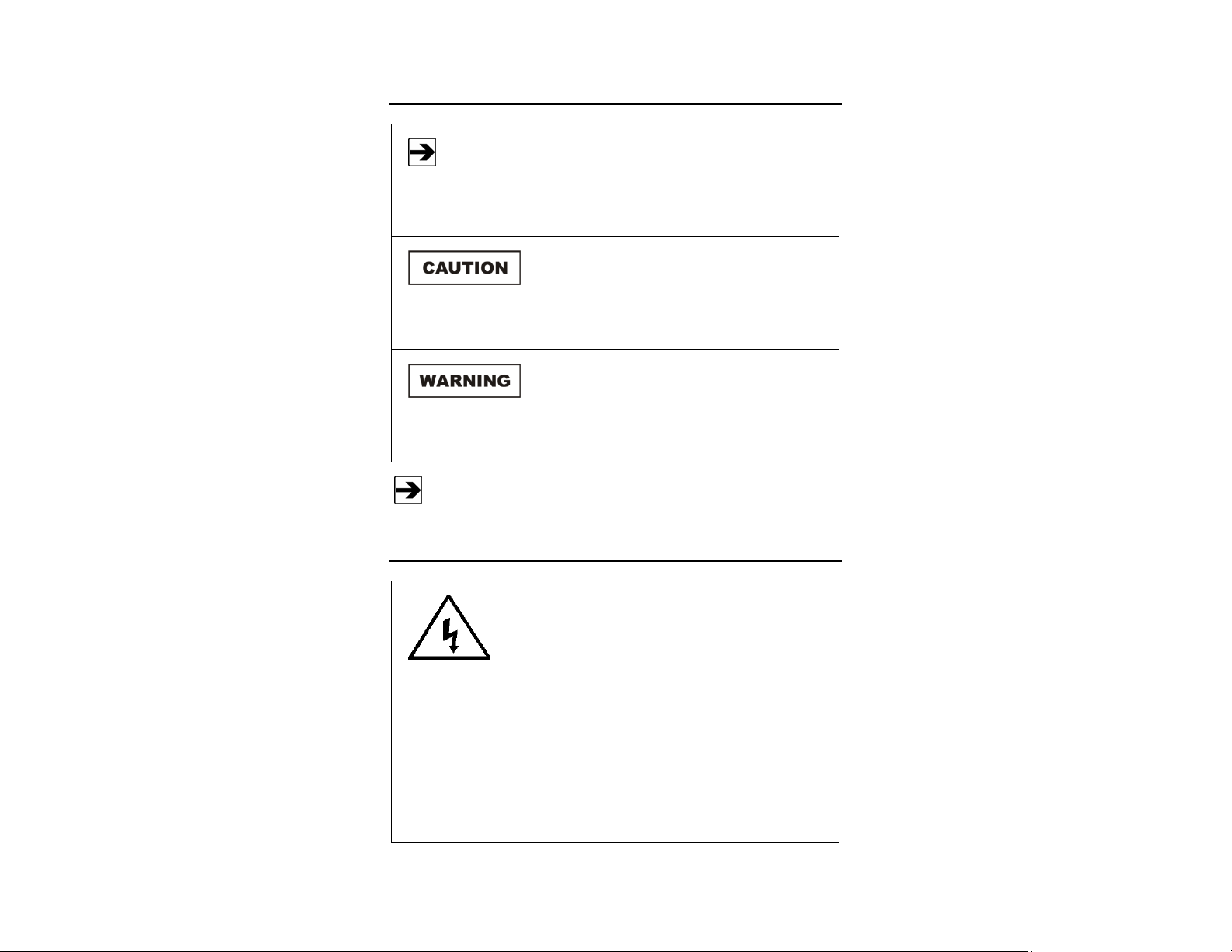
Notes, Cautions, and Warnings
Note: Denotes helpful information intended to
See the ETS-Lindgren Product Information Bulletin for safety,
regulatory, and other product marking information.
provide tips for better use of the product.
Caution: Denotes a hazard. Failure to follow
instructions could result in minor personal injury
and/or property damage. Included text gives proper
procedures.
Warning: Denotes a hazard. Failure to follow
instructions could result in SEVERE personal injury
and/or property damage. Included text gives proper
procedures.
General Safety Considerations
Warning: This is a Safety Class I product
(provided with a protective earthing ground
incorporated in the power cord). The mains
plus shall only be inserted in a socket outlet
provided with a protective earth contact. Any
interruption of the protective conductor,
inside or outside the instrument, is likely to
make the instrument dangerous. Intentional
interruption is prohibited. DO NOT defeat the
earth grounding protection by using an
extension cable, power cable, or
autotransformer without a protective ground
conductor.
| v
Page 6
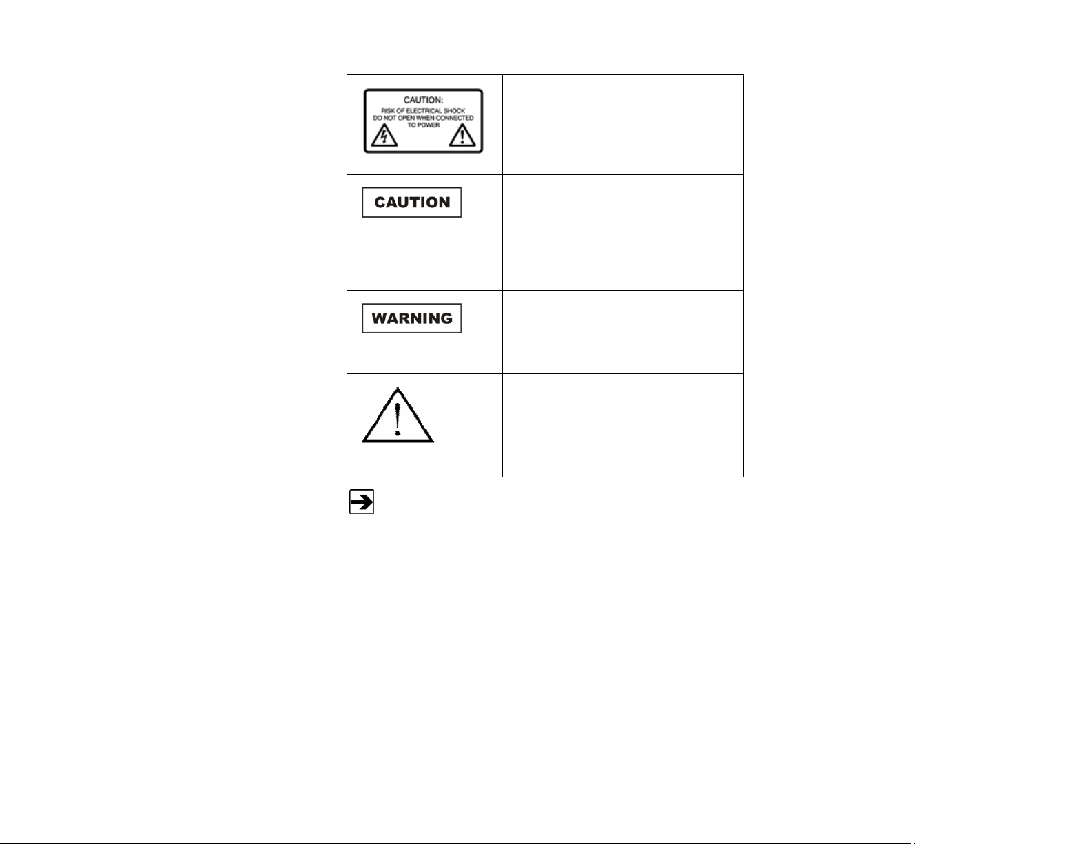
Caution: Uninsulated voltage within the unit
may have sufficient magnitude to cause
electric shock. Therefore, it is dangerous to
make any kind of contact with any parts
inside this unit.
Caution: This instrument is shipped with a
three-wire power cable, in accordance with
international safety standards. When
connected to an appropriate power line
outlet, this cable grounds the instrument
cabinet.
Warning: No operator serviceable parts
exist inside. Refer servicing to qualified
personnel. To prevent electrical shock, do
not remove covers.
Warning: The battery charger incorporates
parts, such as a switch and relay that
potentially could produce sparks or arcs.
Warning: For indoor use only, do not
expose to rain.
vi |
See the ETS-Lindgren Product Information Bulletin for safety,
regulatory, and other product marking information.
Page 7
1.0 Introduction
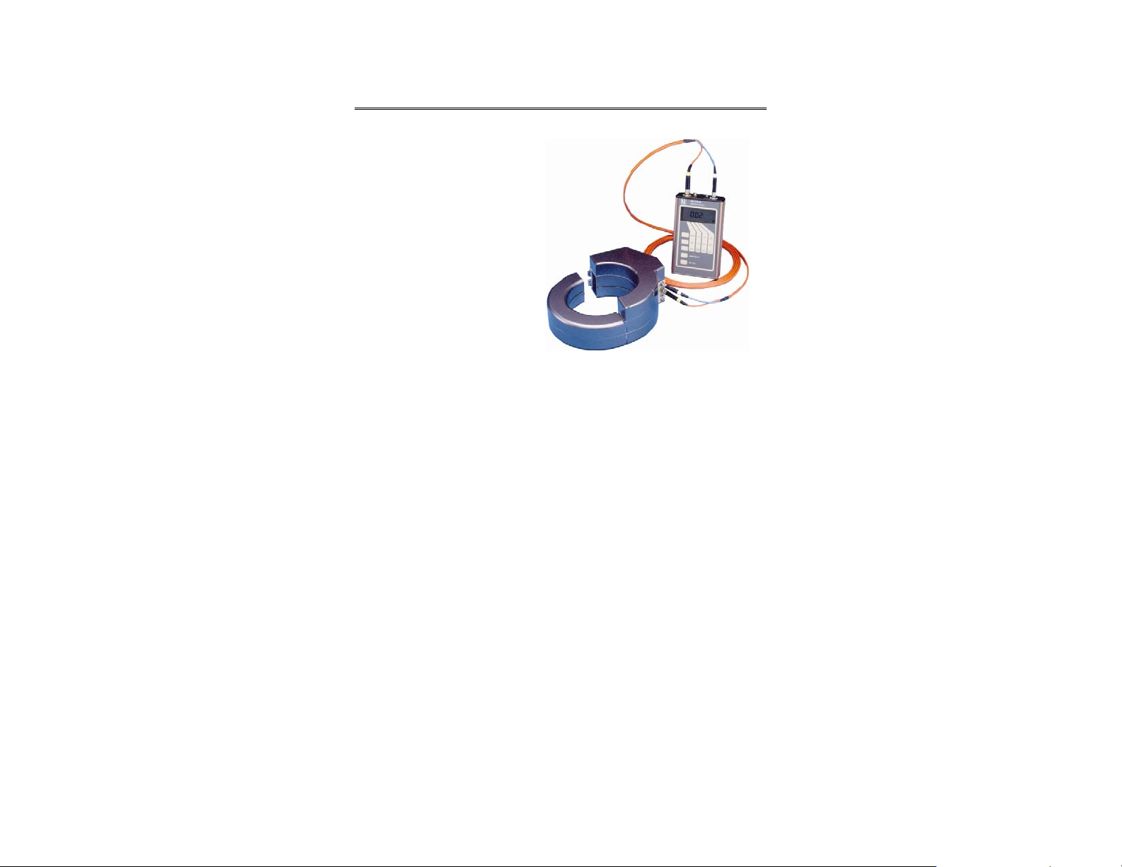
The ETS-Lindgren HI-3702
Clamp-on Induced Current
Meter measures the induced
body current of individuals
working in environments where
radio frequency (RF)
electromagnetic fields are
present. The HI-3702 is designed
to meet the requirements of
IEEE C95.1-1991 Standard for
Safety Levels with Respect to
Human Exposure to Radio
Frequency Electromagnetic
Fields, 3 kHz to 300 GHz.
HI-3702 Clamp-On Current Sensor
HI-4416 Digital Readout/Control Unit
IEEE C95.1-1991 defines the acceptable levels of RF-induced body current for
the frequency range of 3 kHz to 100 MHz. The acceptable levels range from
3 mA for uncontrolled exposures at 3 kHz, to 200 mA for controlled exposures
between 100 kHz and 100 MHz.
Shown:
The accuracy of the HI-3702 provides a means for determining compliance. The
unit is completely portable and self-contained, and is simple to set up and easy to
operate. The rugged design can be used for measurements in environments
such as:
• Induction heating facilities
• Industrial welding applications
• Broadcast transmitting and antenna locations
Introduction | 7
Page 8

Standard Configuration
• HI-3702 Clamp-On Current Sensor with cushioned case
• HI-4416 Digital Readout/Control Unit with fiber optic cable
• Series H-491198-36 Battery Charger
• Carrying Case
Optional Items
• Belt-Pac Readout/Control Unit Case
• HI-4413P Fiber Optic Modem
ETS-Lindgren Product Information Bulletin
See the ETS-Lindgren Product Information Bulletin included with your shipment
for the following:
• Warranty information
• Safety, regulatory, and other product marking information
• Steps to receive your shipment
• Steps to return a component for service
• ETS-Lindgren calibration service
• ETS-Lindgren contact information
8 | Introduction
Page 9
2.0 Maintenance
Before performing any maintenance,
follow the safety information in the
ETS-Lindgren Product Information
Bulletin included with your shipment.
WARRANTY
Take care to keep dirt and moisture from getting inside the housing of the
HI-3702 Clamp-on Induced Current Meter and on the coplanar surfaces of the
ferrite core that are exposed when the clamp-on sensor is open. The cushioned
case provides only minimal protection to the clamp-on sensor in keeping dirt or
other particulate matter from entering the gap on the inner side of the housing.
Do not use high-pressure sprays, and under no circumstance should the unit be
immersed in water or other liquid; the HI-3702 is not waterproof. Such actions
void the warranty.
Maintenance of the HI-3702 is limited to
external components such as cables or
connectors.
Do not open the HI-3702 housing.
Warranty may be void if the housing is
opened.
If you have any questions concerning
maintenance, contact ETS-Lindgren
Customer Service.
Maintenance | 9
Page 10

Battery Maintenance
Under normal operating conditions, recharging the battery is the only
HI-3702 maintenance performed by the user.
Maintaining the HI-3702 requires that the nickel-cadmium (NiCd) battery be
properly charged and the battery condition monitored. The normal operational life
of the battery (approximately 1000 charge/discharge cycles) is such that by the
time the battery needs replacement; the HI-3702 will need recalibration; these
tasks are performed by ETS-Lindgren. For information on calibration services,
see Annual Calibration on page 10.
For the steps to charge the battery, see page 20.
In case of damage to the battery that causes premature failure, the HI-3702 must
be sent to ETS-Lindgren for battery replacement; replacement in the field is not
possible. See Service Procedures on page 11 for information on returning the
HI-3702 to ETS-Lindgren for service.
Annual Calibration
See the Product Information Bulletin included with your shipment for information
on ETS-Lindgren calibration services.
Maintenance of Fiber Optics
Fiber optic connectors and cables can be damaged from airborne particles,
humidity and moisture, oils from the human body, and debris from the connectors
they plug into. Always handle connectors and cables with care, using the
following guidelines.
10 | Maintenance
Page 11
Before performing any maintenance, disconnect
the fiber optic cables from the unit and turn off
Replacement and Optional Parts
Following are the part numbers for ordering replacement or optional parts for the
HI-3702.
power.
When disconnecting fiber optic cables, apply the
included dust caps to the ends to maintain their
integrity.
Before connecting fiber optic cables, clean the
connector tips and in-line connectors.
Before attaching in-line connectors, clean them
with moisture-free compressed air.
Failure to perform these tasks may result in
damage to the fiber optic connectors or cables.
Part Description Part Number
HI-3702 Cushioned Case H-51560044
HI-3702 Fitted Carrying Case H-491132
HI-4416 Digital Readout/Control
Unit
Fiber Optic Cable, 2-meter H-491106-02
Series H-491198-36
Battery Charger
Belt-Pac Readout/Control Unit Case H-51560045
HI-4413P Fiber Optic Modem HI-4413P
12V Auto Lighter Power Cord H-22270-1534D
HI-4416
H-491198-36
Maintenance | 11
Page 12

Service Procedures
For the steps to return a system or system component to ETS-Lindgren for
service, see the Product Information Bulletin included with your shipment.
12 | Maintenance
Page 13

3.0 Ranges and Specifications
Ranges
Autorange: 1.00 mA–1.000 A
Range 1: 1.00 mA–10.0 mA
Range 2: 3.1 mA–31.6 mA
Range 3: 10.0 mA–100.0 mA
Range 4: 0.031 A–0.316 A
Range 5: 0.100 A–1.000 A
Specifications
Typical Frequency Response: 9 kHz–70 MHz ±2.0 dB
Linearity: ±0.5 dB
At lower levels, the linearity for
Range 1 deviates within ±0.5 dB
due to noise. The remaining ranges
follow the ideal curve as shown for
Range 2 in Typical Frequency
Response on page 15.
Fiber Optic Connectors: Standard FSMA
Fiber Optic Cable: 200 micron, Graded Index,
Multimode, Max Length 1 Km
Readout: HI-4416 Digital Readout/Control
Unit
Ranges and Specifications | 13
Page 14

Physical Specifications
HI-3702 Inner Diameter: 105.4 mm (4.15 in)
HI-3702 Outer Diameter: 171.4 mm (6.75 in)
HI-3702 Height: 72.6 mm (2.86 in)
HI-3702 Weight: 1.7 kg ( 3 lb 13 oz)
HI-4416 Digital Readout/Control
Unit:
Cushioned Case: 0.085 kg (3.0 oz)
Fiber Optic Cable: 0.071 kg (2.5 oz)
Battery / Battery Charger
Battery: 3.6 VDC, 1400 mAH rechargeable
Battery Charger: 115/230 VAC, approximately
Battery Life: Approximately 5 hours of continuous
Environmental
Humidity: 5% to 95% relative humidity,
Operating Temperature: 10°C–40°C (50°F–104° F)
0.42 kg (14.8 oz)
nickel-cadmium (NiCd)
one hour
operation per full charge
non-condensing
14 | Ranges and Specifications
Page 15

HI-3702 Typical Frequency Response
Ranges and Specifications | 15
Page 16

This page intentionally left blank.
16 | Ranges and Specifications
Page 17

4.0 Operation
1. Charge the battery.
Before taking any
measurements, charge
the battery to maximum
capacity. For the steps to
charge the battery, see
page 20.
The nickel-cadmium
(NiCd) battery installed in
the HI-3702 Clamp-on
Induced Current Meter
was charged prior to
shipment; however, NiCd
batteries can
self-discharge to nearly
zero capacity after
two months.
Before connecting any components, follow the
safety information in the ETS-Lindgren
Product Information Bulletin included with your
shipment.
If you use this equipment in a manner not
specified by ETS-Lindgren, the protection
provided by the equipment may be impaired.
Do not position the equipment so that it is
difficult to connect cables to or disconnect
cables from the back of the unit.
The battery charger requires approximately one hour to charge the battery to
maximum capacity. Under normal operation, a fully-charged battery should
provide five hours of operation. If the battery fails to hold a charge or if a
significant degradation in operational time occurs, you may need to replace the
battery.
Operation | 17
Page 18

2. Connect the fiber optic cables.
Connect the fiber optic cable to the HI-3702 and to the HI-4416 Digital
Readout/Control Unit. Follow the color coding on the fiber optic cable, the
HI-3702, and the HI-4416.
3. Power on the HI-3702.
Turn on the HI-3702. The HI-3702 is equipped with a locking lever on/off
switch. Pull the switch lever out before toggling it to the appropriate position.
4. Power on the HI-4416.
Turn on the HI-4416. See the HI-4416 manual for more complete operating
information.
5. Select the range.
Use the HI-4416 to select the range that is appropriate for the expected
current levels to be measured. To select auto range, scroll through the ranges
until Range A appears on the screen.
When auto range is enabled, the probe will scroll up to the next higher range
when the reading displayed exceeds full scale. The probe will scroll down to
the next lower range when the reading displayed is -14 dB (20%) of the full
scale reading for the current range. This will put the reading at approximately
2/3 of full scale of the next lower range. See the following Auto Range
Readings Table and Auto Range Flow Diagram.
Range -20dB of
full scale
1 1 mA 7.2 mA 10 mA 10 mA
2 3.16 mA 20 mA 7.2 mA 31.6 mA 10 mA 31.6 mA
3 10 mA 72 mA 20 mA 100 mA 31.6 mA 100 mA
4 31.6 mA 200 mA 72 mA 316 mA 100 mA 316 mA
5 100 mA 200 mA 316 mA 1000 mA
Reading
after scroll
down
-14dB of
full scale;
scroll down
point
Full scale
scroll up
point
Reading
after scroll
up
18 | Operation
Full scale
reading
Page 19

Auto Range Readings Table
Auto Range Flow Diagram
6. Select averaging.
Use the HI-4416 to select Instantaneous Readings or One-Second
Averaging. The HI-3702 collects a measurement approximately seven times
per second. When the X-axis is selected, each measurement is sent to the
display. When the Y-axis is selected, the one-second average of the
measurements is displayed. The averaging algorithm stores the seven most
recent measurements. Each time a measurement is taken, the algorithm drops
the oldest value, adds in the new value, and then recalculates the average and
sends the new average value to the display.
7. Attach the clamp-on curre nt sensor.
Place the clamp-on current sensor on the arm or leg of the body under test
and close the buckle. For accurate measurements, verify that nothing
interferes with complete closure of the clamp-on current sensor. Make sure no
clothing is caught between the coplanar surfaces of the ferrite core material or
the aluminum housing.
Displayed readings that are less than 10% of the full scale reading for the
selected range are not valid. When Range 1 or Autorange is selected and there
is no current passing through the current meter, a noise floor reading will display.
This is a normal operating condition.
Operation | 19
Page 20

Computer Controlled Data Logging
The HI-3702 is
connected for data
logging as shown.
Software is available for the personal computer that simulates the HI-4416. For
information on using the HI-4416 for data logging, see the HI-4416 manual.
Use the optional RS-232 cable assembly (part #H-2239615) to connect the
HI-3702 to the HI-4413P Fiber Optic Modem. This provides direct input of
HI-3702 data into a personal computer or other data logging device.
Battery Charging
Never attempt to recharge a non-rechargeable
battery.
If the battery has been through its normal life span of approximately
1000 charge/discharge cycles, return the HI-3702 to ETS-Lindgren for
battery replacement and recalibration. For more information, see
Battery Maintenance on page 10.
1. Turn off the HI-3702.
2. Connect the battery charger to an AC outlet.
20 | Operation
Page 21

3. Plug the charger jack completely into the CHARGE connector on the
clamp-on current sensor.
Allow approximately one hour for a full charge cycle. When charging is
complete, the battery charger automatically goes into a trickle charge.
It will remain in trickle charge mode until disconnected from the
HI-3702.
4. When the charge cycle is complete, remove the charger jack from the
CHARGE connector on the clamp-on current sensor.
5. Unplug the battery charger from the AC outlet.
6. Use the HI-4416 to verify that the battery is charged to approximately
3.8 VDC.
See Series H-491198-36 Battery Charger on page 27 for complete information
on the battery charger.
Error Codes
If an error occurs, the probe will respond with one of the following strings. These
strings begin with a colon and end with a carriage return.
E01 Communication error (for example, overflow)
E02 Buffer full error; too many characters contained between the
start character and carriage return sequence
E03 Received command is invalid
E04 Received parameter is invalid
E05 Hardware error (for example, EEPROM failure)
E06 Parity error
E9 Received command is invalid
Operation | 21
Page 22

This page intentionally left blank.
22 | Operation
Page 23

5.0 Functional Theory of Operation
Following is a functional theory of operation for the HI-3702 Clamp-on Induced
Current Meter. The objective is to enhance user understanding of the theory
behind the design to aid with the operation and maintenance of the HI-3702.
The HI-3702 is designed to measure RF induced current flowing through the
ankles or arms of the body under test, even while walking or climbing. The fiber
optically coupled readout/control unit does not perturb the measured RF field or
the current distributions. The sensor is a ferrite split core current transformer. The
signal generated by the sensor is amplified by 10 dB to 50 dB depending on the
range that is selected. There is 20 dB of linearity for each range. This signal is
applied to a True RMS Thermal RMS to DC Converter. The DC voltage output of
the True RMS Thermal RMS to DC Converter is applied to a 12 bit
A/D converter. This digital representation of the DC voltage is read by the
microprocessor, converted to a number that is representative of current being
sensed, and transmitted through the fiber optic interface to the HI-4416 Digital
Readout/Control Unit.
Functional Theory of Operation | 23
Page 24

This page intentionally left blank.
24 | Functional Theory of Operation
Page 25

Appendix A: Warranty
See the Product Information Bulletin included with your shipment for
the complete ETS-Lindgren warranty for your HI-3702.
DURATION OF WARRANTIES FOR HI-3702
All product warranties, except the warranty of title, and all remedies for warranty
failures are limited to one year.
Product Warranted Duration of Warranty Period
HI-3702 Clamp-on Induced
Current Meter
Series H-491198-36
Battery Charger
1 Year
1 Year
Warranty | 25
Page 26

This page intentionally left blank.
26 | Warranty
Page 27

Appendix B: Series H-491198-36 Battery Charger
The HI-3702 Clamp-on Induced Current Meter contains a
nickel-cadmium (NiCd) battery, and uses the Series H-491198-36
Battery Charger.
SAFETY PRECAUTIONS
Before operating the Series H-491198-36 Battery
Charger, see General Safety Considerations on
page v.
INTRODUCTION
The Series H-491198-36 Battery Charger
is a dual power source battery charger. It
charges 3.6 Volt 1400 mAH NiCd batteries
and is powered by 120-240 VAC line power
or 12.5 VDC. The H-491198-36 charger
uses a -(dV)/(dT) negative delta
V technique to determine when the battery
is fully charged, which is typically one hour.
With this technique, the charge state of the
battery has no effect other than shortening
the charge time.
Housed in a rugged enclosure, power enters the battery charger through a power
entry module, which contains the fuses, or an optional cigarette lighter plug
adapter. The front face of the battery charger displays LEDs that provide the
operating status. The battery charger connects to the device being charged
through a short cord terminated with a power jack.
An integrated circuit within the battery charger monitors the battery voltage and
controls the charging functions according to the charge state of the battery.
Series H-491198-36 Battery Charger | 27
Page 28

CHARGING A BATTERY
Never attempt to recharge a non-rechargeable
battery.
For the steps to charge a battery, see page 20.
CHARGING INDICATORS
The following LEDs are located on the front of the battery charger:
• POWER ON (green)—Indicates the battery charger is connected to the
AC power source.
• NO BATTERY (amber)—Indicates the battery charger does not detect
a battery.
• PENDING (amber)—Indicates the battery charger detects a battery.
Before fast charging can begin, the battery voltage must fall within
predetermined acceptable limits. A pulse-trickle charge is provided to
bring a depleted battery to a valid charge prior to fast charge.
• CHARGING (amber)—Indicates the voltage pre-qualification condition
has been met, and fast charge has started.
• COMPLETE (green)—Indicates a fast charging peak voltage is
detected. The Field Probe can remain connected to the battery charger
indefinitely while in this maintenance mode.
28 | Series H-491198-36 Battery Charger
Page 29

SPECIFICATIONS
Power
Main: IEC filtered AC power input module
110-240 VAC, 500 mA max,
50-100 Hz
Alternate: Automobile cigarette lighter to 2 mm
power plug adapter cord, 12.5 Vdc,
100 mA
Fuses: 250 Volt, 1.0 Amp,
Type T (5 mm x 20 mm)
Output
Open Circuit Voltage: 15 Vdc
Fast Charge Pending Current: 60 mA
Fast Charge Current: 1400 mA
Pulsed Trickle Charge Current: 50 mA
Output Voltage (During Fast
Charge):
NiCd Battery:
Series H-491198-36 Battery Charger | 29
3–6 Vdc
Battery
• 3.6 Volt 3 Cell NiCd Battery,
1400 mAH (rapid charge cells,
1.2 Volts/cell)
• ETS-Lindgren Part #491038
Page 30

Environmental
Operating Temperature: 10°C–40°C (50°F–104°F)
Humidity: 5% to 95% relative humidity,
non-condensing
MAINTENANCE RECOMMENDATIONS
• Operate the battery charger with care.
• There are no user serviceable parts inside the battery charger.
Opening the battery charger housing may void your warranty.
REPLACING THE FUSE
Disconnect the battery charger from power
before replacing a fuse.
If the battery charger fails to operate, check for a blown fuse inside the power
entry module. A blown fuse must be replaced with the same value and type of
fuse, or an unsafe condition may result. Use only 250 Volt, 1.0 Amp, Type T
(5 mm x 20 mm) fuses.
To replace a fuse:
1. Two fuses are located in the fuse drawer in the power input module.
Use a screwdriver to open the drawer.
2. The fuse towards the outside of the dra wer is the spare. Remove the
spare fuse from the module.
30 | Series H-491198-36 Battery Charger
Page 31

3. Replace the blown fuse with the spare fuse.
4. Slide the fuse drawer back into the module. Make sure that the drawer
snaps securely into its locked position.
Series H-491198-36 Battery Charger | 31
Page 32

This page intentionally left blank.
32 | Series H-491198-36 Battery Charger
Page 33

Appendix C: EC Declaration of Conformity
HI-3702 CLAMP-ON INDUCED CURRENT METER
EC Declaration of Conformity | 33
Page 34

SERIES H-491198-36 BATTERY CHARGER
34 | EC Declaration of Conformity
 Loading...