

Page 1
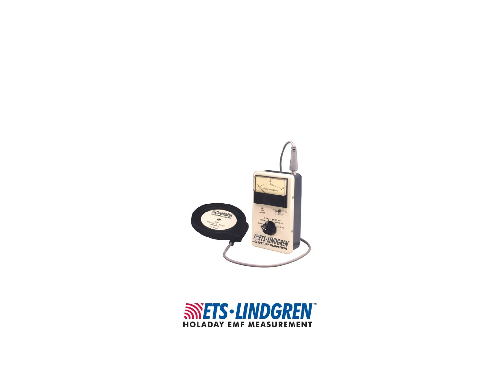
Model HI-3624A
ELF Magnetic Field Meter
User Manual
Page 2
ETS-Lindgren L.P. reserves the right to make changes to any product described
herein in order to improve function, design, or for any other reason. Nothing
contained herein shall constitute ETS-Lindgren L.P. assuming any liability
whatsoever arising out of the application or use of any product or circuit
described herein. ETS-Lindgren L.P. does not convey any license under its
patent rights or the rights of others.
© Copyright 1991–2009 by ETS-Lindgren L.P. All Rights Reserved. No part
of this document may be copied by any means without written permission
from ETS-Lindgren L.P.
Trademarks used in this document: The ETS-Lindgren logo is a trademark of
ETS-Lindgren L.P.
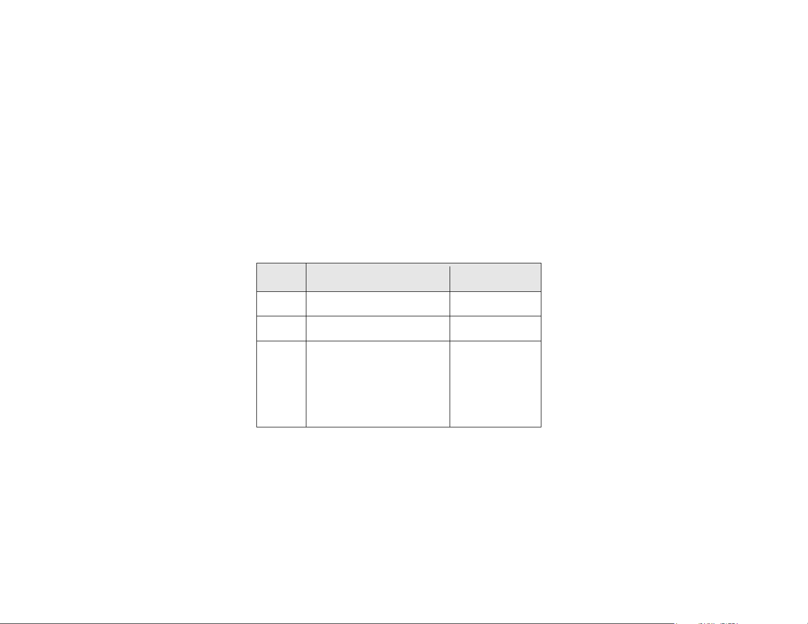
Revision Record | HI-3624A ELF Magnetic Field Meter, MANUAL
Part #H-600044, Rev. B
Revision Description Date
Initial Release April, 1991
A Added CE, updated January, 2000
B Updated branding: Revised to
meet Style Guide specifications;
reformatted to half-size; PIB
included with release; Remove HI3624 reference. Remove VDT
reference.
ii |
July, 2009
Page 3

Table of Contents
Notes, Cautions, and Warnings ................................................ v
1.0 Introduction .......................................................................... 7
Standard Configuration .................................................................................. 8
ETS-Lindgren Product Information Bulletin ................................................... 8
2.0 Maintenance ......................................................................... 9
Battery Replacement ..................................................................................... 9
Annual Calibration ......................................................................................... 9
Service Procedures ....................................................................................... 9
3.0 Specifications ..................................................................... 11
Electrical Specifications ............................................................................... 11
Physical Specifications ................................................................................ 11
4.0 Practical Application and Use .......................................... 13
Example Application .................................................................................... 13
5.0 Operation ............................................................................ 17
Appendix A: Warranty ............................................................. 19
Appendix B: EC Declaration of Conformity .......................... 21
| iii
Page 4

This page intentionally left blank.
iv |
Page 5
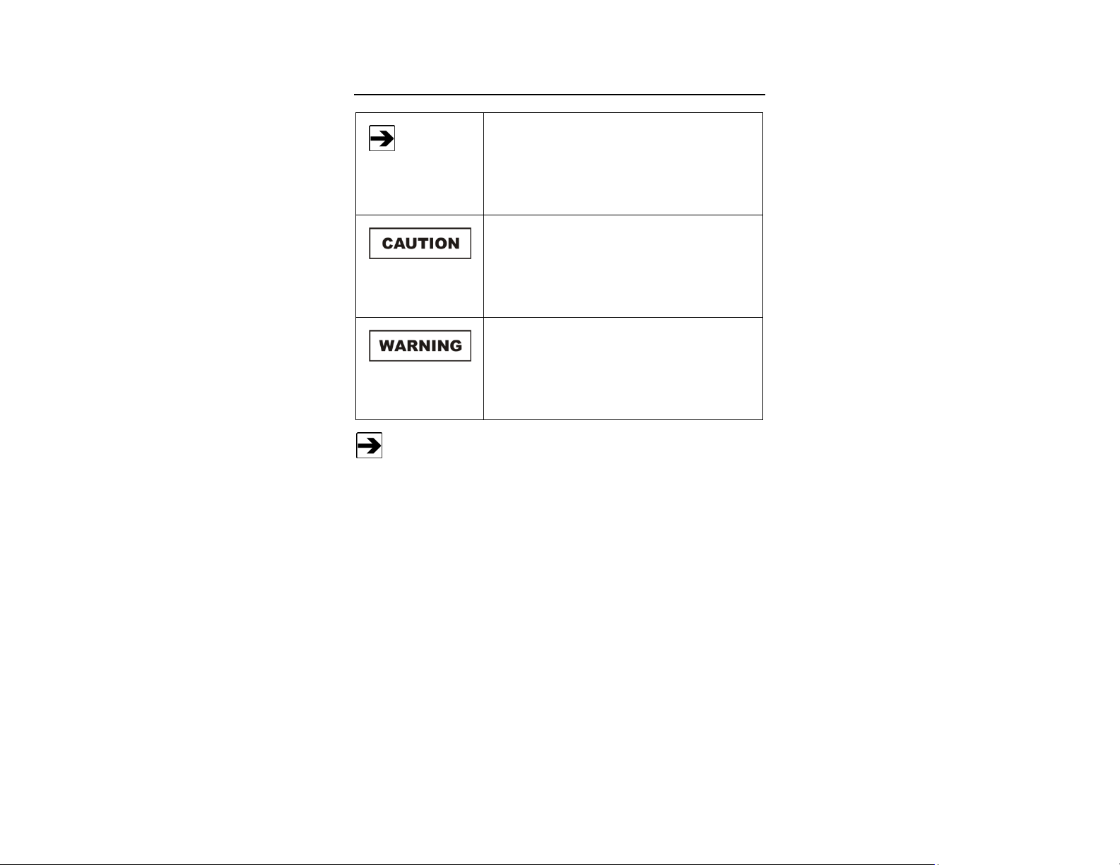
Notes, Cautions, and Warnings
Note: Denotes helpful information intended to
See the ETS-Lindgren Product Information Bulletin for safety,
regulatory, and other product marking information.
provide tips for better use of the product.
Caution: Denotes a hazard. Failure to follow
instructions could result in minor personal injury
and/or property damage. Included text gives proper
procedures.
Warning: Denotes a hazard. Failure to follow
instructions could result in SEVERE personal injury
and/or property damage. Included text gives proper
procedures.
| v
Page 6

This page intentionally left blank.
vi |
Page 7
1.0 Introduction
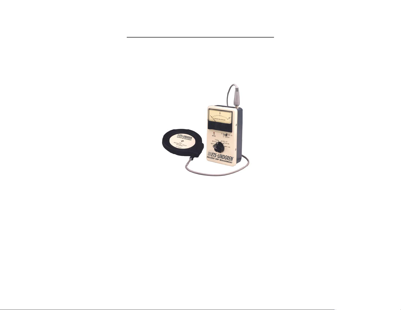
The HI-3624A ELF Magnetic Field Meter is designed to measure the flux density
of magnetic fields in the frequency range of 30 Hz to 2 kHz. The Model
HI-3624A provides for a switch selectable measurement range from 5 Hz to 2
kHz. It finds application in the measurement of magnetic fields associated with
electric power lines and electrically operated appliances.
The HI-3624A is a single axis flux density meter designed to be responsive to
either sinusoidal or complex magnetic fields. It directly displays the root-meansquare (rms) value of magnetic flux density on an analog meter. The sensor
consists of a multi-turn loop connected to the instrumentation readout package
via a one meter long cable.
The separate loop sensor provides for orientation of the sensor relative to the
various magnetic field polarization components. This allows quick assessment of
the greatest flux density value while conveniently holding the instrument for easy
meter reading. This feature makes the HI-3624A especially useful for rapid,
large area surveys of magnetic fields.
The field sensor loop is electrically shielded; consequently the response of the
HI-3624A is solely due to magnetic fields. No interference is caused by ambient
strong electric fields like those found beneath high voltage, overhead electric
power lines or nearby radio or television stations.
Introduction | 7
Page 8

The HI-3624A has a wide dynamic measurement range. The range provides for
full scale ranges of as small as 2 milligauss to as great as 20 gauss. This large
dynamic range makes the HI 3624A convenient for measurement of ambient
residential magnetic fields as well as high level fields found near high current
carrying conductors or electrical machinery.
Standard Configuration
• Meter
• Probe
• Manual
ETS-Lindgren Product Information Bulletin
See the ETS-Lindgren Product Information Bulletin included with your shipment
for the following:
• Warranty information
• Safety, regulatory, and other product marking information
• Steps to receive your shipment
• Steps to return a component for service
• ETS-Lindgren calibration service
• ETS-Lindgren contact information
8 | Introduction
Page 9

2.0 Maintenance
Before performing any maintenance, follow
the safety information in the ETS-Lindgren
Product Information Bulletin included with
your shipment.
WARRANT Y
Maintenance of the HI-3624A is limited to
external components such as cables or
connectors.
If you have any questions concerning
maintenance, contact ETS-Lindgren
Customer Service.
Battery Replacement
Two 9 volt alkaline batteries power the HI-3624A ELF Magnetic Field Meter. To
replace the batteries, remove the eight screws located on the back of the meter,
pull the panel away from the chassis and unplug the battery connectors. Install
the new batteries and reverse the proceeding steps to reassemble the meter.
Annual Calibration
See the Product Information Bulletin included with your shipment for information
on ETS-Lindgren calibration services.
Service Procedures
For the steps to return a system or system component to ETS-Lindgren for
service, see the Product Information Bulletin included with your shipment.
Maintenance | 9
Page 10

This page intentionally left blank.
10 | Maintenance
Page 11

3.0 Specifications
Electrical Specifications
Frequency Response 5 to 2000 Hz Flat
5 Hz -3 dB
2000 Hz -3 dB
<5 Hz Falling 80 dB/decade
>2000 Hz Falling 80 dB/decade
Detector Response
Sensitivity
Accuracy Within ±5% at calibration frequencies of 50,
Linearity 2%
True rms field indication for accurate
measurement of non-sinusoidal waveforms.
Full scale ranges of:
2 mG, 20 mG, 200 mG, 2 G, 20 G
±5% at calibration frequencies of 50, 100, 500
and 1000 Hz
100, 500 and 1000Hz
Physical Specifications
Power Two, 9 volt alkaline batteries
Battery Life Up to 120 hours intermittent use
Inside diameter = 110 mm
External Multi-Turn
Loop Sensor
Cable Length 1.2 m
Outside diameter =116 mm
Area = 0.010 m2
Specifications | 11
Page 12

Instrument accuracy is derived from a field calibration using a one meter
diameter pair of Helmholtz coils for establishing an accurately known magnetic
field flux density. A precisely controlled and measured sinusoidal current is driven
through the Helmholtz coils and, based on the dimensions of the coils; the
magnetic field flux density between the coils in milligauss (mG) is calculated.
While the HI-3624A indicates magnetic flux density (B) in units of milligauss, the
flux density in microtesla or magnetic field strength (H) in milliamperes per meter
may be obtained via the following relations:
1 microTesla = 10 mG
1 mG = 80 milliamperes per meter (mA/m)
12 | Specifications
Page 13

4.0 Practical Application and Use
Before operating any components, follow the
safety information in the ETS-Lindgren
Product Information Bulletin included with your
shipment.
Example Application
Power Lines
Magnetic fields near overhead power lines can be easily measured with the
HI-3624A. An approach commonly used to characterize power line fields is to
measure the flux density along a straight line which passes perpendicular to the
power line. Generally, readings are first taken along the length of a span of the
power line to identify the point at which the greatest flux density exists. Then at
this point take the readings perpendicular to the power line. Take readings every
five to ten feet and orient the sensor for maximum reading. A magnetic field flux
density profile can then be developed. This method is outlined by the Institute of
Electrical and Electronics Engineers (IEEE) in the American National Standards
Institute (ANSI) standard 644 1987
A similar approach may be used for measuring the flux density produced by
buried lines. In this case, the area must be explored by walking about with the
meter, simultaneously moving the sensor in various orientations, until the region
of maximum flux density is found.
Practical Application and Use | 13
Page 14

Residential Measurements
Magnetic fields found in home environments are highly variable, depending on
location within the home. This variability is strongly related to the distribution of
the wiring in the home, the location of electrical appliances and occasionally, the
location of plumbing lines or other metallic structures within the ground which
may form low resistance paths for electrical ground return currents. Establishing
what the ambient magnetic field environment is in a home usually requires
numerous measurements throughout the home, with at least one measurement
within each room. Normal practice would include at least one field measurement
taken near the center of each room. A more thorough approach would include
five measurements in each room, one at the center and one near each corner of
the room. A reasonable technique is to position the sensor at a point
approximately one meter from each room corner for the flux density
measurement. This avoids, to an extent, placing the sensor immediately next to
wiring which may be hidden within the walls of the room and which may yield
unrealistically high values of flux density compared to what most individuals
within the room might be exposed.
Surveys of the areas near electrical appliances will usually reveal higher values
of flux density due to the currents flowing within motors or heating elements.
Logical choices would include the location of beds, for example, since this is a
location of extended occupancy. In characterizing the magnetic fields near
obvious sources, such as appliances, it is often helpful to measure and record
the flux density value at intervals of a few inches (or centimeters) beginning near
the surface of the device. These data will help provide a perspective on the
spatial extent of the elevated field levels and the significance of the levels relative
to other values determined elsewhere within the home. Field measurements
should take into account the likelihood that individuals may have access to areas
where measurements are contemplated.
Because 60-Hz magnetic fields produced by the use of electricity within the home
are dependent on the magnitude of current flowing within wires or the operation
of appliances, flux densities will be seen to vary with time, being greater when
more electrical power is being used. For example, when heating or air
conditioning systems turn on or the compressor within a refrigerator cycles on,
the flux density will increase. Measurements must take this condition into
account and it is recommended that, when taking measurements in a room, the
meter be watched for a period of time to observe for fluctuations in the indicated
value of flux density. After some experience, it may be possible to relate the
observed fluctuations to various uses of electricity within the home.
14 | Practical Application and Use
Page 15

A phenomenon which has recently received some attention in regard to
residential magnetic fields is the flow of earth currents via plumbing lines or
telephone cables buried beneath the home. In some cases, it has been noted
that 60-Hz magnetic fields exist within a home, even when the home is not using
any electrical power (the circuit breakers have all been turned off at the main
electrical service box of the home). This observation has, in some cases, been
related to the flow of currents beneath the home on pipes or cables. It is not
unusual for currents, related to other neighbors' use of electricity, to flow back to
the electrical supply via low resistance paths formed by metal plumbing pipes or
wires used for telephones as opposed to the electrical system neutral wire. In
such cases, it is possible to measure magnetic flux densities within the home
without any apparent reason if the power to the home has been shut off.
Practical Application and Use | 15
Page 16

This page intentionally left blank.
16 | Practical Application and Use
Page 17

5.0 Operation
Before placing into operation, follow the safety
information in the ETS-Lindgren
Product Information Bulletin included with your
shipment.
The ELF magnetic field sensor must be plugged into the HI-3624A meter case for
proper operation; it makes no difference whether the sensor is plugged in before
or after the meter is turned on.
The main switch turns on the instrument and selects one of five ranges for
measurement. A second switch controls the desired low frequency cutoff. A
"Low Battery" LED glows when the batteries are low. If the "low Battery" indicator
remains on replace both of the batteries which are accessible from the back side
of the meter case (instructions for replacing batteries may be found in the
Maintenance section of this manual). It is normal for the LED battery indicator to
briefly blink while turning the switch to various ranges and when turning the
instrument off.
When beginning field measurements, successively turn the range switch to the
right, increasing the instrument's sensitivity until an upscale reading on the meter
is obtained. Most accuracy is achieved when the meter reads approximately
midscale. At each range setting, while holding the meter in one hand, rotate the
sensor with the other hand so as to obtain a maximum indication on the meter.
Because the sensor is capable of measuring only one polarization component of
the magnetic field at any specific time, there are two methods that can be used
for measurements. In the majority of cases, it is sufficient to orient the sensor so
that a maximum indication on the meter is observed. In many instances this will
be a measurement of the resultant magnetic flux density. The sensor must be
rotated about three axes which are each perpendicular to one another. This can
be quickly accomplished with a little practice.
Operation | 17
Page 18

In other cases, the root-sum-squared resultant value of flux density may be
obtained by taking three orthogonal measurements of the field; in this case, the
sensor is successively oriented in three mutually perpendicular directions around
a fixed point and the individual readings recorded. The mutually perpendicular
directions will be denoted as X, Y, and Z. The resultant flux density is then found
by forming the root-sum-squared value from the individual readings as follows:
2
+ By2 + Bz2)
B = (Bx
B = resultant flux density; B
= Reading in the y direction; Bz = Reading in the Z direction.
B
y
1/2
= Reading in the X direction;
x
It does not matter which orientation of the field sensor is used for the X
orientation but the Y and Z orientations must be perpendicular to one another
and the X orientation.
The user may select the lower frequency of the band pass for the instrument as
either 30 Hz or 5 Hz. It should be noted that when the instrument is switched to
the 5 Hz lower frequency cutoff, the unit will be very sensitive to motion of the
sensor since movement within the earth's constant field will appear as a signal to
the instrument. When the sensor is accelerated or rotated within a constant field,
there will be an output from the sensor at a frequency corresponding to the
movement and this will usually include frequency components greater than 5 Hz.
Consequently, during such movement, the meter will typically show significant
upscale indications. The 5 Hz frequency cutoff setting is primarily useful for
measurements at fixed coil positions. For area surveys of ELF fields, the 30 Hz
cutoff will be more useful.
18 | Operation
Page 19

Appendix A: Warranty
See the Product Information Bulletin included with your shipment for
the complete ETS-Lindgren warranty for your HI-3624A ELF Magnetic
Field Meter.
DURATION OF WARRANTIES FOR HI-3624A ELF MAGNETIC FIELD
METER
All product warranties, except the warranty of title, and all remedies for warranty
failures are limited to one year.
Product Warranted Duration of Warranty Period
HI-3624A ELF Magnetic Field Meter 1 Year
Warranty | 19
Page 20

This page intentionally left blank.
20 | Warranty
Page 21

Appendix B: EC Declaration of Conformity
EC Declaration of Conformity | 21
Page 22

This page intentionally left blank.
22 | EC Declaration of Conformity
 Loading...