

Page 1
HI-3520
Archived 4/2/10
Microwave Monitor
User's Manual
Copyright © 1993 Holaday Ind. Inc.
Manual #600052 10/97 $12.50
Page 2

Revision Record
Archived 4/2/10
Manual # 600052
HI-3520
Microwave Monitor
Revision Description Date
--- Preliminary Release 4/93
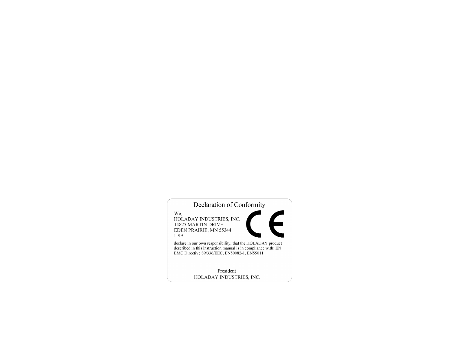
A Added CE Label 10/97
Page 3

TABLE OF CONTENTS
Archived 4/2/10
1.0 PRODUCT OVERVIEW ................ 1
1.1 Introduction ................... 1
2.0 SPECIFICATIONS .................... 3
3.0 OPERATION ........................ 5
3.1 General Information ............... 5
3.2 Safety Precautions ............... 5
3.3 Operating Controls and Indicators .... 6
3.4 Operating Procedure .............. 6
3.5 Set-up Mode ................... 7
3.6 Setting Alarm Warning Level ........ 8
3.7 Enabling/Disabling Audible Alarm ..... 8
3.8 Measurement Modes .............. 8
3.9 "Average" Measurement Mode ....... 8
3.10 "Instantaneous" Measurement Mode .. 9
3.11 Latched Alarm ................. 9
3.12 Built-In Test Functions ........... 10
4.0 THEORY OF OPERATION .............. 11
4.1 RF Circuit .................... 11
4.2 DC Circuit .................... 11
4.3 RF Shielding ................... 12
5.0 MAINTENANCE ..................... 13
5.1 General ...................... 13
5.2 Battery Replacement ............. 13
5.3 Trouble Shooting ............... 14
6.0 CALIBRATION ...................... 17
6.1 General ...................... 17
6.2 Calibration Procedure ............. 17
6.3 Test Data Sheet Model HI-3520 ..... 20
Page 4

LIMITED WARRANTY
Archived 4/2/10
Holaday Industries, Inc. warrants each Model HI-3520
Microwave Monitor to be free from defects in material and
workmanship for a period of one year from date of shipment to
the purchaser. This warranty extends to the original purchaser
only and does not apply to batteries or any product or parts
subject to misuse, neglect, accident, unauthorized service or
abnormal conditions of operations.
In the event of instrument failure covered by this warranty,
Holaday Industries, Inc. will, without charge, repair and
recalibrate the instrument if returned to their factory within one
year of the original purchase, provided that Holaday Industries'
examination discloses to its satisfaction that the product was
defective. Holaday Industries, Inc may, at its option, replace the
product in lieu of repair. If the defect was caused by misuse,
neglect, accident, unauthorized service or abnormal conditions
of operations, repairs will be billed at a nominal cost. In such
case, an estimate will be provided before work is started if
requested by the purchaser.
For warranty service, contact Holaday Industries, Inc., giving full
details of the failure and the serial number of the instrument.
You will then be given service information or shipping
instructions. Return the instrument to the factory, transportation
prepaid. Repairs will be made at the factory and the instrument
returned to you, transportation paid. Holaday Industries, Inc.
assumes no responsibility for loss of, or damage to, products in
transit.
!! WARNING !!
Special caution is advised when working in environments where
contact with high voltage or high current circuits or apparatus is
possible. This is particularly true when attempting to obtain
induced body current measurements near electrically-powered
equipment, such as heat sealers, or in areas marked with
warnings about the presence of high voltages, currents, or RF
fields. Accidental contact with objects, circuits, or fields
operated at high voltages or high current can be lethal! Holaday
Industries, Inc. assumes no liability for damages or personal
injury which may result from accidents arising out of the use of
this equipment.
Page 5

HI-3520 Manual Page 1
Archived 4/2/10
1.0 PRODUCT OVERVIEW
1.1 Introduction
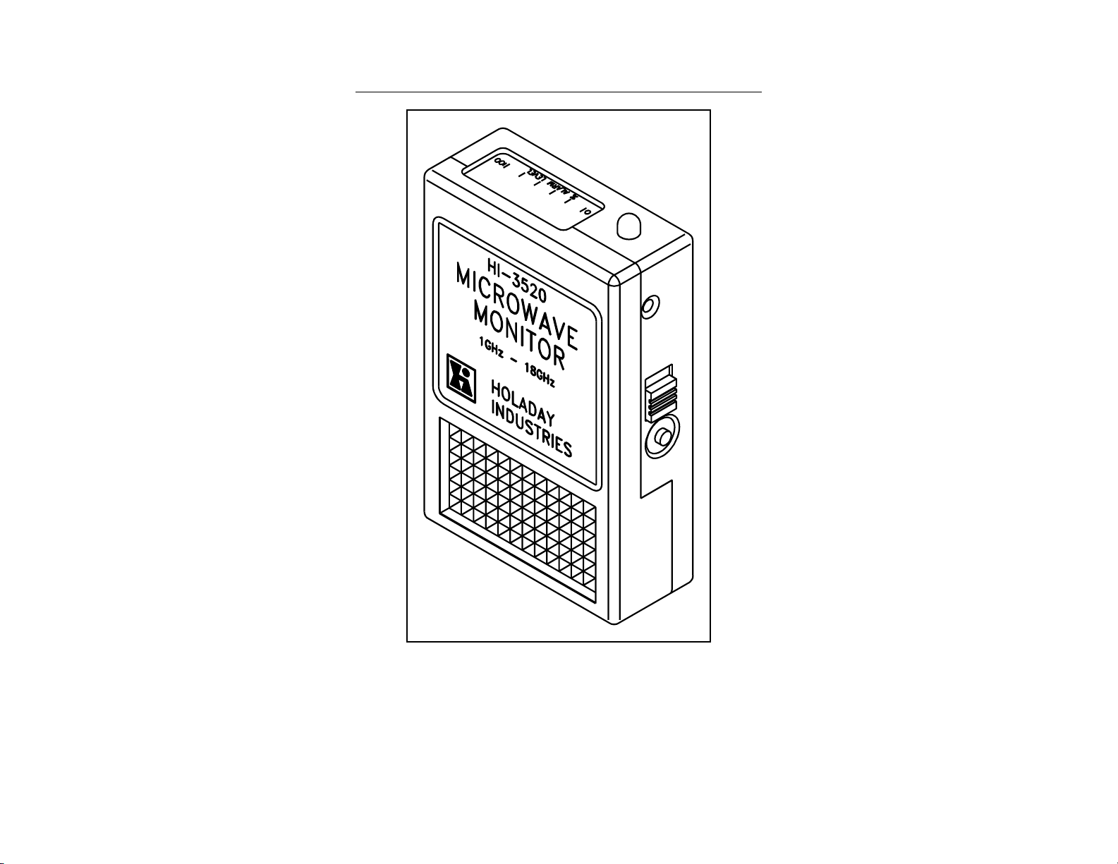
The Model HI-3520 RF Radiation Badge (see Figure 1) is
a portable, battery operated, non-ionizing radiation hazard
detector intended for personal use. It detects
electromagnetic radiation from RF and microwave sources
in the frequency range from 1 to 18 GHz and alerts the
user to potentially hazardous fields. The Model HI-3520
enables the user to set the alarm warning level anywhere
in the range from 0.2 to 20 mW/cm2. In addition, the
user can choose either of two measurement modes:
instantaneous exposure level or a six minute average
measurement. Both modes are displayed on a three digit
LCD panel along with a ten segment bar graph normalized
to the selected alarm warning level. Electrical,
mechanical and performance characteristics are described
in section 2.0.
The Model HI-3520 is intended for use by personnel who
work with or service RF and microwave equipment such
as:
! Microwave Ovens
! Medical Equipment
! Radar Installations
! Microwave Heaters and Dryers
! Communication Systems
! Electronic Warfare Systems
Page 6
Page 2 HI-3520 Manual
Archived 4/2/10
HI-3520 Microwave Monitor
Figure 2
Page 7
HI-3520 Manual Page 3
Archived 4/2/10
2.0 SPECIFICATIONS
HI-3520 Technical Specifications
SPECIFICATION DESCRIPTIVE
DATA
Frequency Range: 1 to 18 GHz
Power Density Range: 0.01 to 20
mW/cm
Alarm Accuracy: ± 2dB
Half Power Beam Width:
Horizontally Polarized
Vertically Polarized
Average Power
Overload:
Peak Power Overload: 100 W/cm
Pulse Energy
Density Overload: 150 W-:sec/cm
Temperature Range:
Operating
Non-Operating
Battery:
Type
Life
Size:
inches
mm
Weight:
oz
gm
90°
120°
0.5 W/cm
-10° C to +50° C
-40° C to +65° C
DL2450B, Lithium
1000 hours
2.40 x 3.75 x 1.00
61.0 x 95.3 x 25.4
4.8
136
2
2
2
2
Page 8

Page 4 HI-3520 Manual
Archived 4/2/10
Page 9

HI-3520 Manual Page 5
Archived 4/2/10
3.0 OPERATION
3.1 General Information
The Model HI-3520 can be carried inside outer garments
or fastened to a shirt or jacket pocket or to a belt using
the clip provided on the instrument. Metallic objects such
as belt buckle, pen, pencil, etc.,could affect the accuracy
of the Model HI-3520. Do not locate the unit near any
metallic object.
NOTE:
The side of the unit containing the clip
should always face towards the
wearer's body.
3.2 Safety Precautions
The following precautions should be observed when
entering an area where unsafe radiation levels may be
expected.
1. Turn on the Model HI-3520. Set it to the
"Instantaneous" Measurement Mode as
described in section 3.10.
2. Enter the area and do a "walkaround". Should
the Model HI-3520 indicate that an alarm
condition exists, take corrective action by
turning off the source of RF power or leaving the
area immediately.
3. Keep the Model HI-3520 turned on and continue
to wear it as long as you are in the area.
Page 10

Page 6 HI-3520 Manual
Archived 4/2/10
3.3 Operating Controls and Indicators
The operating controls on the Model HI-3520 are the ONOFF switch and the Mode switch, both of which are
located on the side of the unit. In addition, the Model HI3520 has three alarm indicators: Two visual indicators
consisting of an LCD display panel and a red LED warning
light, both located on the top of the unit (see figure 2),
and an audible alarm produced by a beeper located within
the unit. Unless programmed off, the audible alarm
operates synchronously with the visual alarm. In
addition, there is an audio output jack to which the
furnished acoustical earpiece can be connected.
3.4 Operating Procedure
To turn the unit ON, place the ON-OFF switch in the ON
position. The unit will respond with a three second beep
and its red LED will glow to confirm that the unit is
operational. In addition, all segments of the LCD display
will be on during this three second interval. The LCD
display will then indicate the preset alarm warning level
for about seven seconds. The unit will then respond with
a short beep and red LED flash. At this time, the unit is
operational and will indicate the power density in the area
as well as the ratio of the power density in the area to
the preset alarm warning level (% ALARM LEVEL bar
graph). This display is normalized to the programmed
alarm level so that the alarm indicates when the bar
graph reaches 100%. Using this display, the wearer can
tell how closes he or she is to the alarm without being
exposed to an alarm power level. (If you are working in
a noisy environment, connect the acoustical earpiece to
ensure hearing the audible alarm). When there are no RF
fields present higher that the preset alarm warning level,
there will be no further alarm indications from the unit.
Should the unit detect a field that exceeds the preset
alarm warning level, the unit will start to beep and flash.
Page 11

HI-3520 Manual Page 7
Archived 4/2/10
The beep and the flash rate are directly proportional to
the RF field strength. Note that once the alarm starts, it
will latch at the minimum flash rate, continuing to warn
of an over-exposure even if the RF field that caused the
alarm is no longer present. In order to reset the alarm
function, the unit must be turned OFF and back ON using
the ON-OFF switch. For information concerning disabling
the latch function, refer to section 3.11. For information
concerning "Instantaneous" vs "Average" measurement
modes, refer to section 3.8.
HI-3520 Display
Figure 3
3.5 Set-up Mode
The "Set-up" mode is used to set the alarm warning level
and to enable/disable the audible alarm. To enter this
mode, set the "ON-OFF" switch to ON. Then depress the
MODE switch after the initial three second period
referenced in section 3.4. The LCD display will indicate
"S.U.". At this point, the alarm warning level can be
changed (section 3.10) or the audible alarm indicator can
be enabled or disabled (section 3.7).
3.6 Setting Alarm Warning Level
Page 12

Page 8 HI-3520 Manual
Archived 4/2/10
In the "Set-Up" mode (section 3.5), depress and hold the
MODE switch. After three seconds, the preset alarm
warning level will be displayed. Release the MODE
switch. Depressing and holding the MODE switch again
at this point will result in a rapidly increasing alarm
warning level indication. Continue to depress the MODE
switch until the desired alarm level is approached. Then
release the MODE switch and pulse it at a convenient
rate until the desired alarm warning level is reached.
Once it is reached, set the ON-OFF switch to OFF and
then to ON again. The alarm warning level that has just
been set will remain in memory until changed again as
described above.
3.7 Enabling/Disabling Audible Alarm
In the "Set-Up" mode (section 3.5), continue to depress
and release the MODE switch and observe that the
audible alarm indicator (a small bell in the upper left area
of the LCD display) appears and disappears. If an audible
alarm is desired, allow the audible alarm indicator to
remain visible; if an audible alarm is not required,
continued to depress and release the MODE switch until
the audible alarm indicator disappears. Using the ON-OFF
switch, turn the unit OFF and then ON again.
3.8 Measurement Modes
The Model HI-3520 Measurement Mode can be set to
either "Instantaneous" or "Average" by depressing and
releasing the MODE switch while the unit is in its normal
operating mode. See sections 3.9 and 3.10.
3.9 "Average" Measurement Mode
When the AVG annunciator on the left side of the display
area is visible, a six-minute running average is maintained
by the unit. Power density is sampled every 3.6
seconds. During the first six minutes (i.e.-360 seconds
Page 13

HI-3520 Manual Page 9
Archived 4/2/10
or 100 measurements), the running average of all
measurements taken will be displayed. After six minutes,
each "new" measurement will replace the measurement
taken 363.3 seconds prior to the "new" measurement.
Therefore, the average of the most recent 100
measurements will always be displayed.
The average of the latest 100 measurements is also
compares by the unit to the alarm warning level set by
the operator (section 3.6) to determine the % ALARM
LEVEL ratio. (During the first six minutes of operation,
the running average of all measurements taken will be
compared by the unit to the alarm warning level set by
the operator to determine the % ALARM LEVEL ratio.) If
the % ALARM LEVEL ratio reaches 100%, the unit's
alarm circuitry will be activated, the red LED and the
ALARM annunciator on the LCD will flash every 3.6
seconds, and the audible alarm will sound every 3.6
seconds.
3.10 "Instantaneous" Measurement Mode
When the INST annunciator on the left side of the LCD
display area is visible, the measured power density is
sampled and displayed every 1.8 seconds. (Note that the
Model HI-3520 saves data for six minutes regardless of
the display selected. Switching between "Average" and
"Instantaneous" does affect the data being stored.)
3.11 Latched Alarm
A feature of the unit's alarm system is that the beeps and
flashes are progressive. Once the alarm level has been
reached, the unit will indicate a single beep and flash
each 1.8 second with the "INST" annunciator displayed
or 3.6 seconds with the "AVG" annunciator displayed.
Should the unit detect a field that exceeds the preset
alarm level, the unit will start to beep and flash. The
Page 14

Page 10 HI-3520 Manual
Archived 4/2/10
beep and the flash rate are directly proportional to the RF
field strength. Note that once the alarms start, they latch
at the minimum flash rate, continuing to warn of an over
exposure situation even it the RF field that initially caused
the alarm is no longer present. In order to reset the alarm
function, it is necessary to turn the unit OFF and back ON
using the ON-OFF switch. If it is desired to disable the
latch function, follow the turn-on procedure described in
section 3.4 except depress and hold the MODE switch
before placing the ON-OFF switch to the ON position.
3.12 Built-In Test Functions
The unit generates a beep and flash at turn on to verify
that the alarm indicators are functioning. At this time, all
segments of the LCD display are enabled to indicate that
the display is operating properly. Ten seconds after turn
on. the unit will generate a second beep and flash which
indicated that it is operational. A low battery condition
is indicated if the unit beeps and flashes two times after
the ten second period. To verify, check the LCD display
for a "BAT" indication. In addition, the battery condition
is tested automatically every minute. Should the battery
measure low, the "BAT" indicator will flash and the unit
will beep and flash once a minute. Refer to Section 5.0
for battery replacement procedures.
The unit also contains continuous fault detection circuitry
to alert the user to a RF detector failure. In that event,
the beeper and light will start to beep and flash at a
constant tone and light, and the LCD display will indicate
"FAIL". The unit is no longer usable in this condition and
should be turned off and serviced.
Page 15

HI-3520 Manual Page 11
Archived 4/2/10
4.0 THEORY OF OPERATION
4.1 RF Circuit
The Model HI-3520 RF circuit consists of two orthogonal
tft
1 (thin-film thermoelectric) arrays, each containing a
number of series connecter thermoelectric junctions.
These are mounted between a pair of thermally
conductive dielectric wafers to enhance the detector
sensitivity. When placed in an RF field, the dipoles
absorb power which gives rise to thermal gradients
across the thermocouple junctions. By keeping the
temperature differential small, the detector acts as a true
rms device producing a dc output voltage directly
proportional to the absorbed power.
The tft elements, acting as resistive screens, operate over
the frequency range 1 to 18 GHZ.
1
tft registered trademark of General Microwave
Corporation.
4.2 DC Circuit
The DC output produced by the RF circuit is amplifies by
a differential chopper-stabilized amplifier. This circuit has
high common mode rejection and low DC drift. The high
level output of this circuit is connected to a
microcontroller which has a built in A/D converter. The
amplifier has two gain ranges that are controlled by the
microcontroller.
A self-contained test signal is constantly applied to the
RF detector. Should a fault occur in this circuit, a fault
signal is generated through the DC amplifier which then
generated a fault bit to the microcontroller.
Page 16

Page 12 HI-3520 Manual
Archived 4/2/10
The analog output from the DC amplifier is digitized by
the microcontroller's A/D converter. The reference
voltage for the A/D converter is generated from a bandgap reference diode which provides excellent long term
stability. The microcontroller then controls the
measurement rate for instantaneous or average
measurements, amplifier ranges. LCD display, fault
indications and low battery signals. It store and
computes the data for the six minute average readout and
stores the alarm warning level trip point.
4.3 RF Shielding
To enable accurate operation of the sensitive circuits
within the RF Radiation Badge in the presence of RF
fields, an array of shielded and absorbers is used. The
circuits are contained within a Faraday shielded area
which is then covered by a graded absorber to minimize
field disturbances. To prevent reflections from behind the
unit giving distorted measurements results, the antenna
section is protected by an absorber. The net result is
that the sensitivity to any reflection from the rear of the
unit is minimized relative to its performance in free space.
Page 17

HI-3520 Manual Page 13
Archived 4/2/10
5.0 MAINTENANCE
5.1 General
The unit has been designed for rugged field use. Normal
maintenance for this unit consists only of battery
replacement and calibration.
5.2 Battery Replacement
The unit furnished with a DL2450B lithium cell. Normal
operating life is 1000 hours. With the alarm in its latched
mode, the battery life is about 80 hours. The shelf-life of
the battery is about ten years when stored in a cool
environment.
The unit has a built in battery monitoring circuit that
generates a single beep and flash at one minute intervals
under low battery conditions. To replace the battery,
proceed as follows:
1. Turn the unit off. THIS IS IMPORTANT.
2. Loosen the screw that secures the battery cover
and remove the cover.
3. To remove the battery, pry it up with a small
screwdriver to clear the lip of the battery holder
before sliding it out.
4. Insert the new battery, making sure to observe
the correct battery polarity as indicated on the
retaining clip (i.e., +toward the clip).
5. Turn the unit on. The instrument should now be
operational and the one minute beep and flash
warning indicators should cease.
Page 18

Page 14 HI-3520 Manual
Archived 4/2/10
NOTE:
Should the unit exhibit any form of
unusual or erratic performance, or
doesn't turn on at all, proceed as
follows:
1. Turn the unit off.
2. Slide an insulator such as a piece of paper
between the plus battery clip and the battery.
3. Turn the unit on for five minutes.
4. Turn the unit off and then quickly slide out the
insulator.
5. Turn the unit on. The instrument should now
operate normally.
Once the unit is operating properly, replace the cover and
tighten the cover screw.
The instrument should now be operational and the one
minute beep and flash warning indicators should cease.
5.3 Trouble Shooting
NOTE:
In general, except for normal battery
replacement, trouble shooting and repair of this
instrument by the user is not recommended.
As a part of its self-test capability, the unit will produce
a tone and flash when it is turned on. In the event it fails
to do so, check the condition of the battery by replacing
it in accordance with the procedure described in section
Page 19

HI-3520 Manual Page 15
Archived 4/2/10
5.2 above.
Should the unit continue to malfunction, return it to
Holaday Industries Inc. for repair.
Page 20

Page 16 HI-3520 Manual
Archived 4/2/10
Page 21

HI-3520 Manual Page 17
Archived 4/2/10
6.0 CALIBRATION
NOTE
The following is applicable only to units with
serial numbers higher than 220104. Please
contact the Holaday Industries Inc. for calibration
instructions for units with serial numbers of
220104 and lower.
6.1 General
The Model HI-3520 Radiation Badge should be calibrated
at 12 month intervals. To do so requires the use of
highly specialized test equipment and facilities, such as a
radio-frequency anechoic chamber and test cells, wherein
fields of known power density can be accurately
established. It should also be noted that to establish the
required power densities will require CW sources of 10W
or greater together with accurately calibrated test
antennae and power monitoring equipment. If facilities of
this type are not available, the unit should be returned to
General Microwave or to another qualified calibration
facility for this service.
6.2 Calibration Procedure
Set the alarm warning level to 0.2 mW/cm2 as described
in section 3.6.
Disable the latch function as described in section 3.11.
1.0 Position the unit in an anechoic chamber. The
preferred orientation of the E-field is parallel to
the vertical axis of the unit.
2.0 At 1.4 GHz, raise the power density level at the
unit until an alarm is indicated. Record this
Page 22

Page 18 HI-3520 Manual
Archived 4/2/10
power density level on the test data sheet in
mW/cm
2.
3.0 Repeat step 2.0 at 2.45, 3.8, 8.0, 12.0 and
18.0 GHz.
4.0 From the data in step 2.0 and 3.0, calculate the
average power density measured over the band
by taking the square root of the product of the
highest and lowest readings recorded. Record
the resultant on the data sheet for P
cal
.
5.0 Divide 0.2 mW/cm2 by the power density level
recorded on the data sheet for P
. This
cal
determines the correction multiplier, M.
6.0 Alignment can now be performed at any one of
the calibration frequencies specified in steps 2.0
and 3.0. Select a convenient calibration
frequency.
7.0 At the selected calibration frequency, multiply by
M the indicated power density from the data
recorded in step 2.0 and 3.0 above. Record this
as P
REF
.
8.0 Remove the battery compartment cover and
located the calibration potentiometer behind the
hole adjacent to the battery cover screw hole.
NOTE:
It is necessary to remove the battery cover door
to adjust the calibration potentiometer but the
cover must be replaced for the RF test.
9.0 Apply the P
power at the calibration
REF
frequency. Adjust this potentiometer such that
Page 23

HI-3520 Manual Page 19
Archived 4/2/10
the alarm just starts to indicate. Repeat this
adjustment as required.
10.0 This completes the RF calibration. Replace the
battery compartment cover. Attach a new
calibration sticker with the current calibration
date.
NOTE:
Do not place any stickers or labels that contain
metal on the bottom surface of the unit or the
lower portions (i.e., approximately 1 ½ inches
up from the bottom surface) of the front and
both sides of the unit. This could seriously
affect the accuracy of the unit. Paper or plastic
stickers are acceptable.
Page 24

Page 20 HI-3520 Manual
Archived 4/2/10
6.3 Test Data Sheet Model HI-3520
DATE SERIAL NUMBER TESTED BY
STEPS 2.0 AND 3.0
FREQUENCY (GHz) POWER DENSITY LEVEL (mW/cm
1.4
2.45
3.8
8.0
12.0
18.0
STEP 4.0 P
= (PHI X PLO)
CAL
STEP 5.0 M =
0.2
=
P
CAL
1/2
=
STEP 6.0 CAL FREQ =
2
STEP 7.0 P
= M (POWER DENSITY AT CAL FREQ)
REF
=
STEP 9.0 ALARM SET FOR P
CHECK
REF
Page 25

HI-3520 Manual Page 21
Archived 4/2/10
-- NOTES --
Page 26

Page 22 HI-3520 Manual
Archived 4/2/10
-- NOTES --
 Loading...