

Page 1
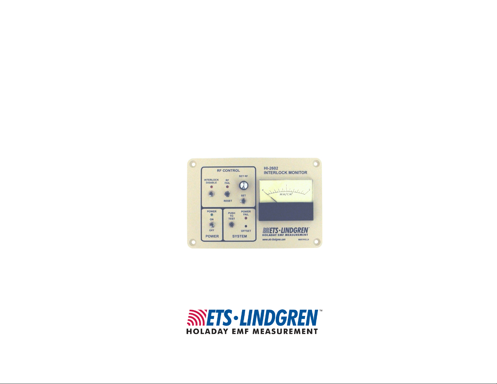
Model HI-2602
Interlock Monitor
User Manual
Page 2
ETS-Lindgren L.P. reserves the right to make changes to any product described
herein in order to improve function, design, or for any other reason. Nothing
contained herein shall constitute ETS-Lindgren L.P. assuming any liability
whatsoever arising out of the application or use of any product or circuit
described herein. ETS-Lindgren L.P. does not convey any license under its
patent rights or the rights of others.
© Copyright 1991–2009 by ETS-Lindgren L.P. All Rights Reserved. No part
of this document may be copied by any means without written permission
from ETS-Lindgren L.P.
Trademarks used in this document: The ETS-Lindgren logo is a trademark of
ETS-Lindgren L.P.
Revision Record | HI-2602 Interlock Monitor, MANUAL | Part #H-600046, Rev. D
Revision Description Date
Preliminary Release September, 1991
A Remote Reset August, 1994
B Output Connector Update April, 2000
C Remote Reset Information October, 2000
D Revised Specifications and Error
Analysis tables. Updated branding:
revised to meet Style Guide
specifications; PIB included with
release
ii |
June ,2009
Page 3

Table of Contents
Notes, Cautions, and Warnings ................................................ v
General Safety Considerations ................................................ v
Introduction ................................................................................ 7
Standard Configuration .................................................................................. 8
ETS-Lindgren Product Information Bulletin ................................................... 8
Maintenance ............................................................................... 9
Maintenance Recommendations ................................................................... 9
Annual Calibration ......................................................................................... 9
Service Procedures ....................................................................................... 9
Specifications ........................................................................... 11
Error Analysis .............................................................................................. 12
Assembly and Installation....................................................... 13
Operation .................................................................................. 15
Front Panel Controls .................................................................................... 15
System Operation ........................................................................................ 16
Appendix A: Warranty ............................................................. 19
Appendix B: EC Declaration of Conformity .......................... 21
| iii
Page 4

This page intentionally left blank.
iv |
Page 5
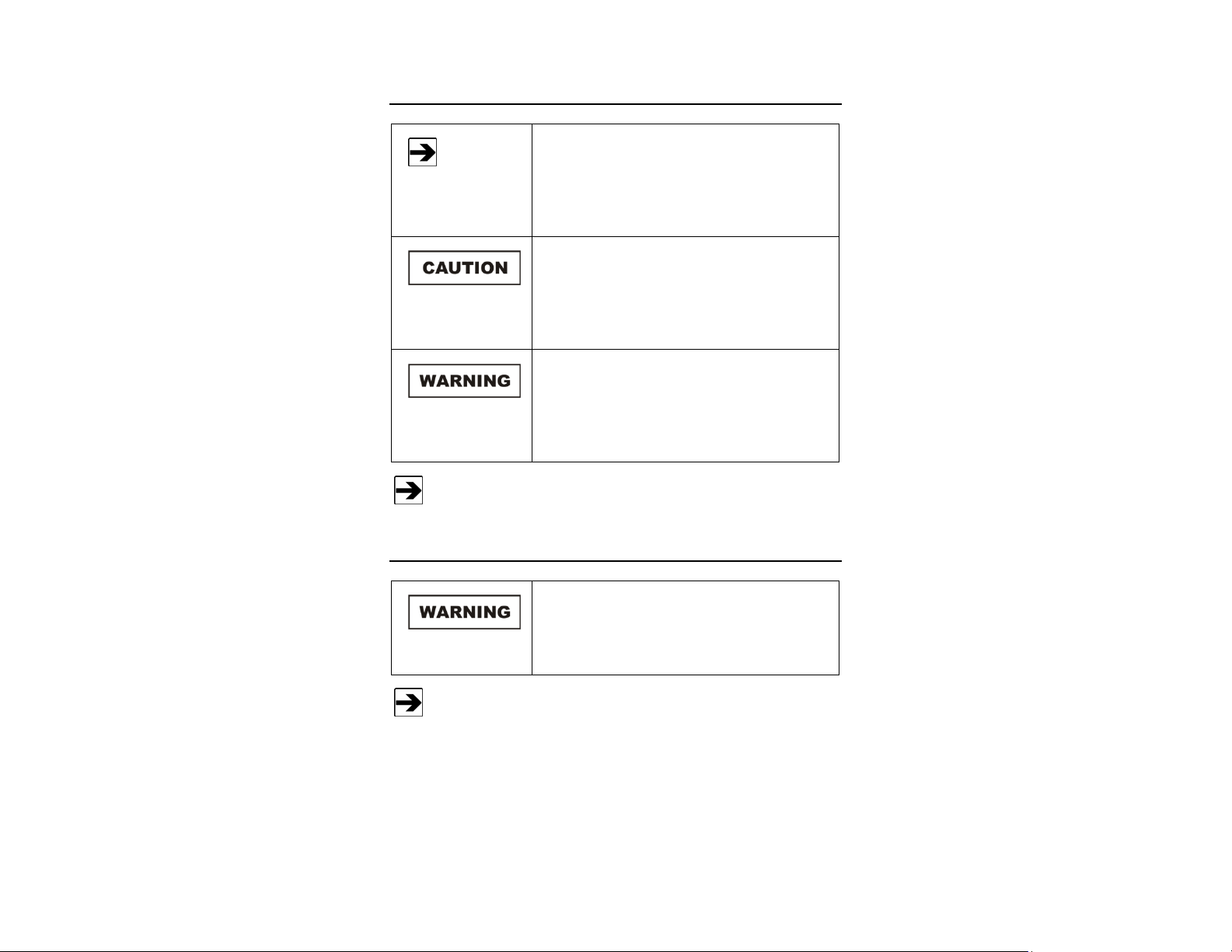
Notes, Cautions, and Warnings
Note: Denotes helpful information intended to
See the ETS-Lindgren Product Information Bulletin for safety,
regulatory, and other product marking information.
provide tips for better use of the product.
Caution: Denotes a hazard. Failure to follow
instructions could result in minor personal injury
and/or property damage. Included text gives proper
procedures.
Warning: Denotes a hazard. Failure to follow
instructions could result in SEVERE personal injury
and/or property damage. Included text gives proper
procedures.
General Safety Considerations
Do not use the HI-2602 without the protective cover
on the sensing end of the probe. Using the
instrument without the cover will result in reading
errors and may damage the probe.
See the ETS-Lindgren Product Information Bulletin for safety,
regulatory, and other product marking information.
| v
Page 6

This page intentionally left blank.
vi |
Page 7
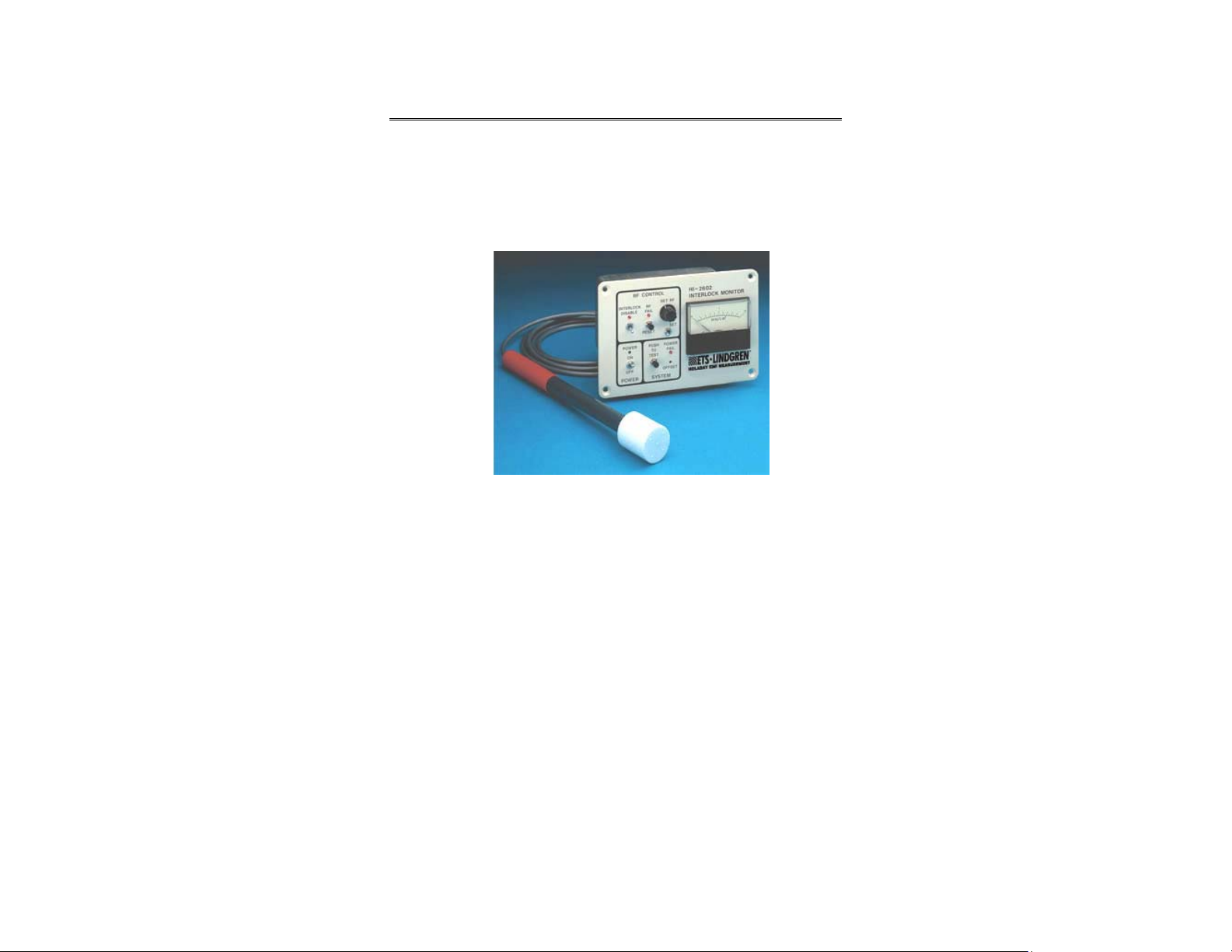
Introduction
The HI-2602 Interlock Monitor provides continuous surveillance of microwave
fields for protection of personnel and equipment. The instrument accepts an input
from a single, remotely mounted sensing probe using ETS-Lindgren’s patented
microwave field sensor. Useable in any critical area, the HI-2602 interlocks with
any microwave source or alarm.
The HI-2602 may be set to trigger at any RF level up to 2.0 mW/cm². When the
RF level sensed by the probe exceeds a preset RF level, the RF Fail indicator
will light and the output interlock will latch
The instrument is calibrated for measurement in the 2450 MHz ISM band only
and is intended for area hazard monitoring. It is not intended for RF leakage
compliance measurements.
The HI-2602 Interlock Monitor is designed to operate from standard 50/60 Hz
120 or 240 VAC power. The AC input power, is customer specified and set at the
factory.
Introduction | 7
Page 8

The diode detection array of eight hot carrier diodes is housed in the large end of
the plastic probe. This antenna array has the unique ability to sum microwave
electric fields of any polarization in a plane perpendicular to the axis of the probe.
The probe is attached to the main unit by a BNC connector. The main unit and
the probe are calibrated as an integral unit. Temporary over-exposure of up to
2000 mW/cm² will not cause probe burn-out or damage to the instrument or its
calibration.
Standard Configuration
• HI-2602 main unit
• Probe cable assembly (including probe sensor cover)
• Amp plug and hood
• Amp pins, 9 pieces
• User manual
ETS-Lindgren Product Information Bulletin
See the ETS-Lindgren Product Information Bulletin included with your shipment
for the following:
• Warranty information
• Safety, regulatory, and other product marking information
• Steps to receive your shipment
• Steps to return a component for service
• ETS-Lindgren calibration service
• ETS-Lindgren contact information
8 | Introduction
Page 9

Maintenance
WARRANT Y
Maintenance Recommendations
Before performing any maintenance, follow
the safety information in the ETS-Lindgren
Product Information Bulletin included with
your shipment.
Maintenance of the HI-2602 is limited to
external components such as cables or
connectors.
To prevent electrical shock, do not remove
cover.
Warranty may be void if the housing is
opened.
If you have any questions concerning
maintenance, contact ETS-Lindgren
Customer Service.
Maintenance of the HI-2602 is limited to external components such as cables or
connectors.
Annual Calibration
It is recommended that the instrument be recalibrated every 12 months. See the
Product Information Bulletin included with your shipment for information on ETSLindgren calibration services.
Service Procedures
For the steps to return a system or system component to ETS-Lindgren for
service, see the Product Information Bulletin included with your shipment.
Maintenance | 9
Page 10

This page intentionally left blank.
10 | Maintenance
Page 11

Specifications
Calibration Calibrated at 2450 MHz for use in the ISM band
Sensitivity 0.2-20.0 mW/cm²
Response
Characteristics
Environmental
Maximum Power
Density
Power Input 120/240 VAC, 50/60 Hz (factory set)
Isolated Output
Contacts
Size
>1 second
(0-90% of final value for step input)
• Operating Temp. 15ºC to 30ºC
(59º F to 86ºF)
• Humidity 5% to 95%*
*relative humidity, non-condensing
2.0 W/cm²
Form C (SPDT) 7.5 amps intermittent, 4 amps
continuous/120VAC
• Probe Length 305mm (12.0 in)
• Probe Cable Length 3.5m (12 ft) standard
15m (50 ft) maximum
• Weight 1.5 kg (3.25 lbs)
Specifications | 11
Page 12

Error Analysis
1.0 mW/cm2
Absolute Calibration +0.30 dB
Precision ±0.13
Linearity and AM response ±0.15
Frequency Response
Near field response ±0.29
Polarization
Pattern +0 / -0.11
Temperature +1.568/ -1.118
Supply Voltage ±0.01
RFI
Overload ±0.01
Drift
-1.068 / +1.568 dB
* ±0.21
* ±0.01
* ±0.04
* ±0.04
* Values are combined in an RMS manner.
12 | Specifications
Page 13

Assembly and Installation
Before operating any components, follow the
safety information in the ETS-Lindgren
Product Information Bulletin included with your
shipment.
The HI-2602 is intended to be installed in a through hole panel mount, using four
#10 flat head screws.
Connect the provided AC power source to the back of the unit.
Assembly and Installation | 13
Page 14

Locate and mount the sensing probe to the Probe Connection port. Caution must
be taken when using metal probe mounts as metal materials close to the sensing
end of the probe may cause inaccurate readings. Direct air flow from heating and
air conditioning vents may also cause erroneous readings.
Route the probe cable so that the probe may be adjusted without placing stress
on the probe to cable connections.
Connect a suitable alarm indicator to the output connector. Check the label
above the connector to ensure the output specifications are not exceeded. Also,
check to ensure the pin numbers of your cable match the pin numbers of the
output connector.
14 | Assembly and Installation
Page 15

Operation
Before placing into operation, follow the safety
information in the ETS-Lindgren
Product Information Bulletin included with your
shipment.
The HI-2602 monitor and probe are calibrated as an integral unit. Care must be
taken not to interchange probes and monitors without recalibration. Operating the
HI-2602 with different probes may cause erroneous readings.
Front Panel Controls
RF Control—contains a switch for disabling the interlock and a red LED to
indicate when RF is over the preset RF fail level. A push button switch is used to
reset the system when the LED illuminates. A momentary toggle switch in
combination with a potentiometer is used to set the RF fail level.
Power—contains the main power switch and a green LED indicator for indicating
power on.
System—contains a potentiometer for adjusting the needle zero, a red LED
indicating power failure and a push button switch for testing the desired RF fail
level.
Analog Meter—indicates RF readings from 0 - 2 mW/cm².
Operation | 15
Page 16

System Operation
Turn the main power switch on; the green LED
illuminates. If not, check the power cord
connections at both ends. Also, check the
2 amp fuse located at the power connector. If
the POWER FAIL indicator lights and stays lit,
discontinue use immediately and contact
ETS-Lindgren. If the INTERLOCK DISABLE or
the RF FAIL indicators are lit, use the
corresponding switch to turn them off.
Allow the system to warm up and stabilize for 5 minutes. With all sources of RF
at the probes turned off, view the analog meter and, if necessary, adjust the
offset potentiometer for a zero reading.
Check the operation of the HI-2602 in active
use by operating the PUSH TO TEST switch.
The RF FAIL indicator will light and the analog
meter will read approximately 2.0 mW/cm².
Before proceeding push the RESET button.
Adjust the RF Fail level by pressing and holding
the SET switch and then adjusting the SET RF
potentiometer until the meter needle indicates
the desired level.
After the RF FAIL point has been adjusted the
reading may be checked by pressing the SET
switch and observing the meter reading.
16 | Operation
Page 17

The range of the HI-2602 is from approximately 0 - 2.0 mW/cm².
The HI-2602 is now operational and will sense RF fields at the probe location.
When the RF level sensed by the probe exceeds the preset RF level, the RF Fail
indicator will light and the output interlock will latch. After detecting excessive RF
leakage, the HI-2602 must be manually reset. The system is reset by operating
the RESET switch.
The HI-2602 can also be reset remotely by applying12 volts DC across pin D(+)
and pin E(-) of the output connector located in the rear panel. The HI-2602 output
operates as a form C contact where pin C is common. During normal operation
pin B is active. During a failure situation it switches latching pin A active.
The RF level at the probe must be below the preset RF level
before the RF Fail can be reset.
For area sensing of maximum RF leakage
operate the INTERLOCK DISABLE switch
illuminating the disable indicator. When the RF
fields at the probe exceed the preset RF level,
the RF Fail indicator will light and stay lit until
the RF field is reduced below the preset RF
level. By moving the probe and observing the
analog meter the maximum leakage area can
be located.
Operation | 17
Page 18

This page intentionally left blank.
18 | Operation
Page 19

Appendix A: Warranty
See the Product Information Bulletin included with your shipment for
the complete ETS-Lindgren warranty for your HI-2602 Interlock
Monitor.
DURATION OF WARRANTIES FOR HI-2602 INTERLOCK MONITOR
All product warranties, except the warranty of title, and all remedies for warranty
failures are limited to one year.
Product Warranted Duration of Warranty Period
HI-2602 Interlock Monitor 1 Year
Warranty | 19
Page 20

This page intentionally left blank.
20 | Warranty
Page 21

Appendix B: EC Declaration of Conformity
EC Declaration of Conformity | 21
Page 22

This page intentionally left blank.
22 | EC Declaration of Conformity
 Loading...