

Page 1

Archived 10/19/10
FM5004
Field Monitor
User Manual
Page 2

ETS-Lindgren L.P. reserves the right to make changes to any product described
Archived 10/19/10
herein in order to improve function, design, or for any other reason. Nothing
contained herein shall constitute ETS-Lindgren L.P. assuming any liability
whatsoever arising out of the application or use of any product or circuit
described herein. ETS-Lindgren L.P. does not convey any license under its
patent rights or the rights of others.
© Copyright 1994–2009 by ETS-Lindgren L.P. All Rights Reserved. No part
of this document may be copied by any means without written permission
from ETS-Lindgren L.P.
Trademarks used in this document: The ETS-Lindgren logo is a trademark of
ETS-Lindgren L.P.
Revision Record | FM5004 MANUAL | Part #H-600069, Rev. B
Revision Description Date
Initial Release January, 1994
A Updates / edits April, 2005
B Rebrand April, 2009
ii |
Page 3

Table of Contents
Archived 10/19/10
Notes, Cautions, and Warnings ............................................... ix
General Safety Considerations ................................................ x
1.0 Introduction ........................................................................ 11
Theory of Operation ..................................................................................... 12
System Theory ..................................................................................... 12
System Block Diagram ................................................................ 13
Receiver Theory .................................................................................. 14
Receiver Block Diagram .............................................................. 15
Zeroing ................................................................................................. 16
ETS-Lindgren Product Information Bulletin ................................................. 16
2.0 Maintenance ....................................................................... 17
Maintenance Recommendations ................................................................. 17
Weekly ................................................................................................. 17
Monthly ................................................................................................ 17
Annual Calibration ....................................................................................... 18
Maintenance of Fiber Optics ........................................................................ 18
Service Procedures ..................................................................................... 18
3.0 Before You Begin ............................................................... 19
Verify FM5004 Operation ............................................................................. 19
Verify Optional Connections ........................................................................ 20
Remote Operation ............................................................................... 20
Analog Output ...................................................................................... 21
4.0 Quick Start .......................................................................... 23
5.0 Front Panel Controls and Indicators ................................ 25
Power Switch ............................................................................................... 25
Input Selection Matrix .................................................................................. 26
Base Mode Switches ........................................................................... 26
Channel Select Switches ..................................................................... 27
Channel Mode Indicators ..................................................................... 28
System Status .............................................................................................. 29
Range (Alt Disp) .................................................................................. 29
Battery (Temp) ..................................................................................... 30
| iii
Page 4

Local (Reset) ....................................................................................... 31
Archived 10/19/10
(Shift) ................................................................................................... 31
Display ......................................................................................................... 31
Menu Select ................................................................................................. 32
Using the Menu Keys ........................................................................... 32
Navigating the Menu System ............................................................... 32
Changing Settings ............................................................................... 33
Exiting the Menu System ..................................................................... 33
6.0 Menu System ...................................................................... 35
MAIN MENU ................................................................................................ 35
DISPLAY SETUP ......................................................................................... 36
DISPLAY FORMAT / ALT DISPLAY FORMAT ................................... 37
4-PROBE ..................................................................................... 38
2-LINE ......................................................................................... 38
3-AXIS ......................................................................................... 40
DISPLAY UPDATE RATE ................................................................... 41
LCD CONTRAST ................................................................................. 41
LCD BRIGHTNESS ............................................................................. 41
ANALOG OUT SETUP ................................................................................ 42
FULL SCALE RANGE ......................................................................... 43
MIN/MAX/AVG ..................................................................................... 44
FILTER SIZE ....................................................................................... 45
LOG SCALE OUTPUT ......................................................................... 45
REMOTE OPER SETUP ............................................................................. 46
ALARM SETUP ........................................................................................... 47
4-PROBE / 3-AXIS ALARM SETUP .................................................... 48
LINE 1 ALARM / LINE 2 ALARM ......................................................... 49
TEMP ALARM SETUP ........................................................................ 50
SYSTEM ALARM ................................................................................. 52
SETUP SAVE/RECALL ............................................................................... 53
ZERO PROBES ........................................................................................... 54
MAINTENANCE ........................................................................................... 54
LAST ERRORS ................................................................................... 54
SYSTEM STATUS ............................................................................... 55
SAMPLES/SEC ................................................................................... 55
KEY CLICK .......................................................................................... 55
iv |
Page 5

ALARM SILENCE ................................................................................ 55
Archived 10/19/10
7.0 Remote Operation .............................................................. 57
Command Set Format ................................................................................. 57
IEEE-488 ..................................................................................................... 57
IEEE-488 Requirements ...................................................................... 57
IEEE-488 (GPIB) Communications...................................................... 58
RS-232 ......................................................................................................... 58
RS-232 Communications ..................................................................... 58
RS-232 Settings ................................................................................... 59
RS-232 Pin Detail ................................................................................ 59
Remote Commands ..................................................................................... 60
Alarm Latch .......................................................................................... 62
Alarm Silence ....................................................................................... 63
Alternate Display Format ..................................................................... 64
Alarm Lower Enable ............................................................................ 66
Alarm Lower Value .............................................................................. 67
Alarm Upper Enable ............................................................................ 68
Alarm Upper Value .............................................................................. 69
Analog Output Mode ............................................................................ 70
Analog Output Range .......................................................................... 71
Baud Rate ............................................................................................ 72
Buss Voltage ........................................................................................ 73
Change Range ..................................................................................... 74
Display Format ..................................................................................... 75
Display Update Rate ............................................................................ 77
Error Register Query ............................................................................ 78
Filter Size ............................................................................................. 79
GPIB Address ...................................................................................... 80
Key Click .............................................................................................. 80
Last Errors ........................................................................................... 81
LCD Brightness .................................................................................... 81
LCD Contrast ....................................................................................... 82
LED Setup ........................................................................................... 83
Local Mode .......................................................................................... 84
Log Scale ............................................................................................. 84
Read Display ....................................................................................... 85
| v
Page 6

Read Battery Voltages ......................................................................... 86
Archived 10/19/10
Read Temperatures ............................................................................. 87
Remote Mode ...................................................................................... 88
Sample Rate ........................................................................................ 89
Setup Recall ........................................................................................ 90
Setup Save .......................................................................................... 91
System Alarm, Hard Probe Failure ...................................................... 92
System Alarm, Momentary Probe Failure ............................................ 93
Software Date ...................................................................................... 93
Software Revision ................................................................................ 94
Verbose Mode ..................................................................................... 94
Zero Probes ......................................................................................... 95
System Level Commands for IEEE-488.2 Compliance ............................... 96
Clear Status ......................................................................................... 96
Define Device Trigger .......................................................................... 97
Event Status Enable ............................................................................ 98
Error Status Register Query ................................................................ 98
Identification Query .............................................................................. 99
Operation Complete ........................................................................... 100
Reset ................................................................................................. 101
Self-Test ............................................................................................ 101
Service Request Enable .................................................................... 102
Status Byte Query .............................................................................. 103
Trigger ............................................................................................... 104
8.0 Troubleshooting and Error Handling ............................. 105
Troubleshooting ......................................................................................... 105
Error Handling ............................................................................................ 106
Error Code A: Alarm L1 Up Line 1 Upper Alarm ................................ 106
Error Code B: Alarm L1 Line 1 Lower Alarm ..................................... 106
Error Code C: Alarm L2 Up—Line 2 Upper Alarm ............................. 106
Error Code D: Alarm L2 Lo—Line 2 Lower Alarm ............................. 106
Error Code E: Probe Err Probe Returned Error ................................. 106
Error Code F: Batt Fail At Fail Level .................................................. 107
Error Code G: Double Flt–Receive–Probe Reset .............................. 107
Error Code H: Probe Fail–Probe Did Not Recover ............................ 107
Error Code L: Temp Lower–Temp Under Lower Limits ..................... 107
vi |
Page 7

Error Code N: Non Support–Probe Not Supported ........................... 107
Archived 10/19/10
Error Code O: Over Range Error ....................................................... 107
Error Code P: Process Err No Time to Process Data ........................ 107
Error Code Q: Sample/s–1 Process Err–Rate Too High ................... 108
Error Code R: Receive Err Data Not Rec From Probe ...................... 108
Error Code S: Send Error Probe Not Ready to Send ........................ 108
Error Code U: Temp Upper Temp Over Upper Limits ....................... 108
Error Code W: Batt Warn At Warning Level ...................................... 108
Error Code Y: Alarm Upper 4/3 Display Alarm .................................. 108
Error Code Z: Alarm Lower 4/3 Display Alarm................................... 108
Appendix A: Warranty ........................................................... 109
Appendix B: Summary List of Commands .......................... 111
IEEE-488.2 Commands ............................................................................. 111
No Parameter Commands ......................................................................... 112
One Parameter Commands ....................................................................... 113
Two Parameter Commands ....................................................................... 114
Three Parameter Commands .................................................................... 114
Appendix C: EC Declaration of Conformity ........................ 115
| vii
Page 8

This page intentionally left blank.
Archived 10/19/10
viii |
Page 9

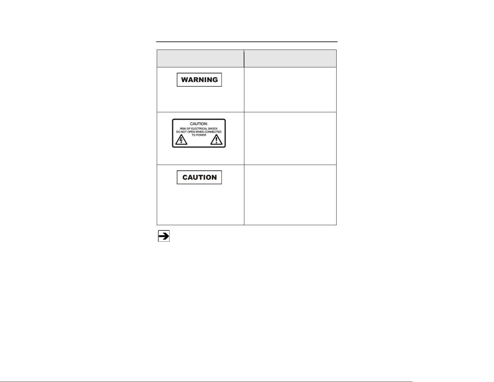
Notes, Cautions, and Warnings
Archived 10/19/10
Note: Denotes helpful information intended to
See the ETS-Lindgren Product Information Bulletin for safety,
regulatory, and other product marking information.
provide tips for better use of the product.
Caution: Denotes a hazard. Failure to follow
instructions could result in minor personal injury
and/or property damage. Included text gives proper
procedures.
Warning: Denotes a hazard. Failure to follow
instructions could result in SEVERE personal injury
and/or property damage. Included text gives proper
procedures.
| ix
Page 10
General Safety Considerations
Archived 10/19/10
Safety Symbol Definition
Warning: No operator serviceable
parts exist inside. Refer servicing to
qualified personnel. To prevent
electrical shock, do not remove
covers.
Caution: Uninsulated voltage within
the unit may have sufficient
magnitude to cause electric shock.
Therefore, it is dangerous to make
any kind of contact with any parts
inside this unit.
Caution: This instrument is shipped
with a three-wire power cable, in
accordance with international safety
standards. When connected to an
appropriate power line outlet, this
cable grounds the instrument
cabinet.
x |
See the ETS-Lindgren Product Information Bulletin for safety,
regulatory, and other product marking information.
Page 11
Archived 10/19/10
1.0 Introduction
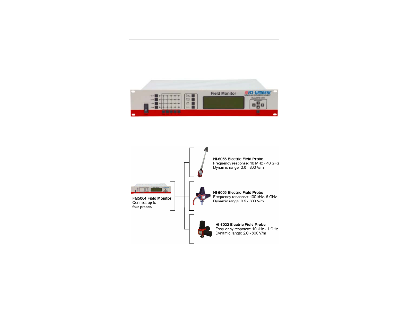
The ETS-Lindgren FM5004 Field Monitor is a broadband electric and magnetic
field monitor designed for use in radio frequency interference and
electromagnetic compatibility (RFI/EMC) test system applications.
The FM5004 is compatible with the following ETS-Lindgren E (electric) field or
H (magnetic) battery-operated field probes.
The FM5004 accepts inputs from up to any four probes, and analyzes and
displays information on a user configurable LCD display.
Introduction | 11
Page 12

Archived 10/19/10
The FM5004 provides two digital interfaces (IEEE-488 and RS-232), a switch
selectable 0–5 VDC analog output, and audible user selected field strength,
temperature, and low probe battery alarms. It has a probe dependent frequency
response of 10 kHz–40 GHz and a sensitivity of 0.5 V/m–3000 V/m,
15.0 mA/m–30 A/m (probe dependent).
Theory of Operation
For information about a specific probe, see the probe manual.
SYSTEM THEORY
A complete FM5004 system consists of one to four field measurement probes
coupled to the FM5004 through fiber optic cables, and optional external devices.
The FM5004 contains fiber optic I/O cards to communicate with the probes, a
main processor board, an LCD to display data and system status, a keypad for
operator control, and an audible alarm to indicate field strengths above or below
a user-defined value. RS-232 and IEEE-488 ports are provided for remote
system operation and data collection, and an analog output port is provided for
leveling purposes.
The probes and I/O cards use microprocessors to provide intelligent control and
operation of the system. Each has a self-contained power supply: a universal
input 110–230 VAC supply for the FM5004, and rechargeable battery packs for
the probes.
When a field strength reading is requested by the FM5004, the I/O card for that
probe sends the appropriate command to the probe through the fiber optic cable.
The probe measures the signal level for each enabled axis, a vector addition is
performed on these readings, and then the result is transmitted to the I/O card
through the fiber optic cables. The I/O card formats the data from the probe and
routes it to the main FM5004 processor for interpretation, display, and
transmission to a remote recorder (if desired).
12 | Introduction
Page 13

Archived 10/19/10
SYSTEM BLOCK DIAGRAM
Introduction | 13
Page 14

Archived 10/19/10
Following are other commands performed by the probes; depending on the
specific probe, additional commands may be available.
• Zero
• Switch range
• Enable/disable axis
• Send temperature/battery voltage
When a probe receives a command from the I/O card it performs the requested
function and sends a response back to the FM5004.
RECEIVER THEORY
The FM5004 issues commands to the I/O cards, then the I/O card issues control
signals to the probe processor. It also receives the data from the probe, formats
it, and relays it to the FM5004 main processor.
The sampling rate, range settings, autorange enable/disable, display format, and
other setup parameters are stored in Electrically Erasable Programmable
Read-Only Memory (EEPROM). The setups are automatically restored each time
the FM5004 is powered on. Flash EEPROM memory is used to store the main
program. Random Access Memory (RAM) is used to temporarily store
measurements and settings.
Inputs to the FM5004 come from the keypad switches on the front panel or from
a remote control device connected through the IEEE-488 or RS-232 ports.
Information from the probes is communicated through the front panel LEDs and
display. Optional receiver outputs include:
• Output to a remote receiver through the IEEE-488 or RS-232 ports
• Analog output (with 12-bit resolution) to recorders or leveling circuitry
• Programmable alarm values for driving a relay that controls a remote
alarm
The FM5004 power supply operates from a 115–230 VAC power source. The
supply provides outputs of +5 VDC, -12 VDC, and +12 VDC.
14 | Introduction
Page 15

Archived 10/19/10
RECEIVER BLOCK DIAGRAM
Introduction | 15
Page 16

Archived 10/19/10
ZEROING
Not all probes have a zero function. For information on zeroing a
probe, see the probe manual.
When a probe receives a zero command from the FM5004, the probe must be in
a zero field. The processor directs the multiplexer to perform a normal read cycle
on all axis signals; this procedure is executed for all 24 settings (four ranges,
three axes per range, two antennas per axis). When the processor receives
these readings, it stores them in a special register, and then these values are
subtracted from all subsequent measurements. Therefore, a probe that is zeroed
when it is not in a zero field environment will give erroneous readings.
ETS-Lindgren Product Information Bulletin
See the ETS-Lindgren Product Information Bulletin included with your shipment
for the following:
• Warranty information
• Safety, regulatory, and other product marking information
• Steps to receive your shipment
• Steps to return a component for service
• ETS-Lindgren calibration service
• ETS-Lindgren contact information
16 | Introduction
Page 17

Archived 10/19/10
2.0 Maintenance
Before performing any maintenance, follow
the safety information in the ETS-Lindgren
Product Information Bulletin included with
your shipment.
WARRANTY
Maintenance of the FM5004 is limited to
external components such as cables or
connectors.
Warranty may be void if the housing is
opened.
If you have any questions concerning
maintenance, contact ETS-Lindgren
Customer Service.
Maintenance Recommendations
W
EEKLY
• Check battery status using front panel switch or remote command.
M
ONTHLY
• Clean contaminants from the front panel with a damp cloth. Always
unplug the unit before cleaning.
• Disconnect fiber optic cables and verify they are clean. See
Maintenance of Fiber Optics on page 18 for cleaning guidelines.
• Inspect cables for kinks, breaks, cracks, and loose connectors.
Maintenance | 17
Page 18

Archived 10/19/10
Annual Calibration
See the Product Information Bulletin included with your shipment for information
on ETS-Lindgren calibration services.
Maintenance of Fiber Optics
Fiber optic connectors and cables can be damaged from airborne particles,
humidity and moisture, oils from the human body, and debris from the connectors
they plug into. Always handle connectors and cables with care, using the
following guidelines.
Before performing any maintenance, disconnect
the fiber optic cables from the unit and turn off
power.
When disconnecting fiber optic cables, apply the
included dust caps to the ends to maintain their
integrity.
Before connecting fiber optic cables, clean the
connector tips and in-line connectors.
Before attaching in-line connectors, clean them
with moisture-free compressed air.
Failure to perform these tasks may result in
damage to the fiber optic connectors or cables.
Service Procedures
For the steps to return a system or system component to ETS-Lindgren for
service, see the Product Information Bulletin included with your shipment.
18 | Maintenance
Page 19
Archived 10/19/10
3.0 Before You Begin
Before connecting any components or placing
into operation, follow the safety information in
the ETS-Lindgren Product Information Bulletin
included with your shipment.
Perform all steps in this section before powering on the FM5004 Field Monitor or
installing it in a test environment.
Verify FM5004 Operation
1. Make sure the probes are fully charged. See the probe manual for
charging information.
2. Remove the protective covers from the fiber optic cable. Inspect the
tips of the cable to verify they are free from dirt and other
contaminants.
Save all protective caps and covers for re-use.
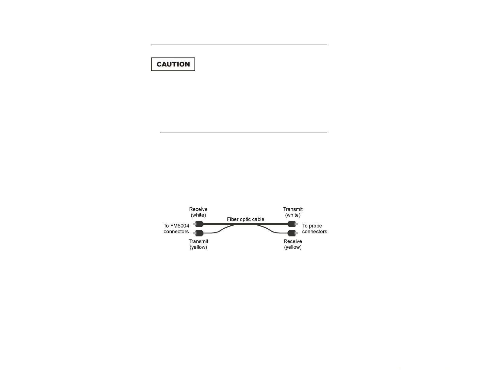
3. Attach the fiber optic cable to the transmit and receive connectors on
the back of the FM5004, matching yellow to transmit and white to
receive.
4. Attach the other end of the fiber optic cable to the probe connectors,
matching white to transmit and yellow to receive.
5. Plug the power cord into the power connector on the back of the
FM5004.
6. Plug the other end of the power cord into an electrical outlet.
Before You Begin | 19
Page 20

Archived 10/19/10
7. Set the ARM/OFF switch on all probes to ARM.
8. Power on the FM5004. A tone will sound, and it will perform a self-test.
If an error occurs, see Troubleshooting and Error Handling on
page 105.
Verify Optional Connections
If optional connections are part of your system configuration, perform a
bench test prior to installing the FM5004.
REMOTE OPERATION
1. Connect the RS-232 or IEEE-488 cable to the appropriate connector.
• If RS-232 remote control is used—See Baud Rate on page 72 for
information on setting the device baud rate.
• If IEEE-488 remote control is used—Set the DEVICE ADDRESS to
the appropriate bus address for your installation. See IEEE-488
Requirements on page 57 for more information.
2. Send an identification query (*IDN?<LF>) from the remote controller;
verify that the FM5004 returns the proper response. See Identification
Query on page 99 for more information.
20 | Before You Begin
Page 21

Archived 10/19/10
ANALOG OUTPUT
1. Connect the appropriate cable to the Analog Out connector on the
back of the FM5004.
2. Enable the analog output system and verify proper operation. See
ANALOG OUT SETUP on page 42 for information on setting up the
analog output system.
Before You Begin | 21
Page 22

Archived 10/19/10
This page intentionally left blank.
22 | Before You Begin
Page 23

Archived 10/19/10
4.0 Quick Start
Before placing into operation, follow the safety
information in the ETS-Lindgren
Product Information Bulletin included with your
shipment.
Before operating the FM5004, complete the steps in Before You Begin
on page 25.
Following are the basic steps to configure and operate the FM5004 Field Monitor.
To save time and improve accuracy during configuration, before you start the
following steps identify the modes and configurations you want for each channel
See Front Panel Controls and Indicators on page 25 for complete
information on using the switches, buttons, and other controls located
on the front of the FM5004.
1. Set the ARM/OFF switch on all probes to ARM.
2. Press on the FM5004.
3. Verify no error codes appear on the FM5004 display and that there are
no fault indications. If an error code appears or a fault is indicated, see
Troubleshooting and Error Handling on page 105.
4. Select the channel to which a probe is connected by pressing the
channel select switch for that channel, and then press Disp.
Select the desired axes and whether the data is for display or for
analog output.
5. If more than one probe is attached, repeat step 4 for each channel.
The configuration is saved in non-volatile memory. It will remain stored unless
altered, regardless of whether the FM5004 is powered on.
Quick Start | 23
Page 24

Archived 10/19/10
This page intentionally left blank.
24 | Quick Start
Page 25
Archived 10/19/10
5.0 Front Panel Controls and Indicators
Before connecting any components or placing
into operation, follow the safety information in
the ETS-Lindgren Product Information Bulletin
included with your shipment.
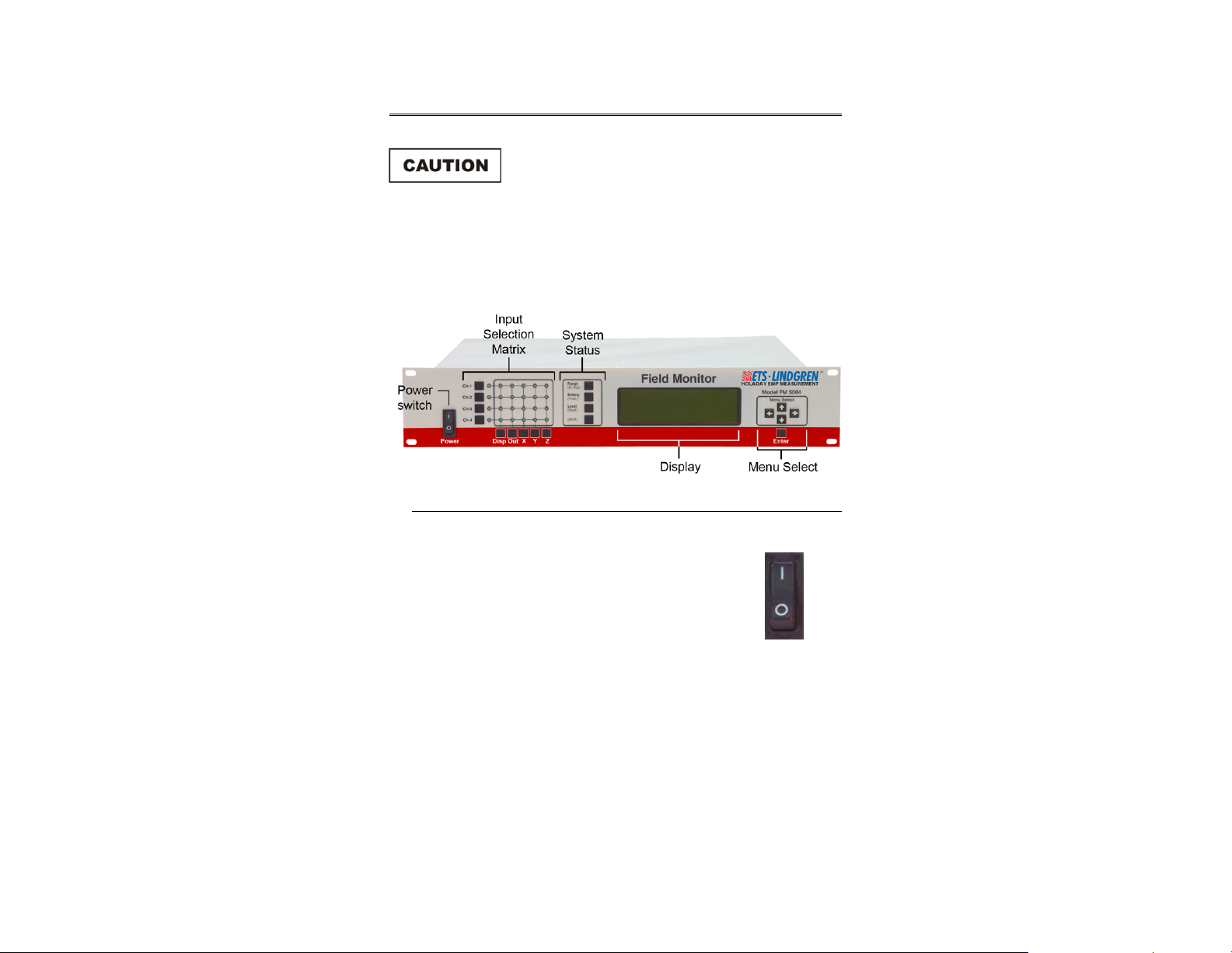
The front panel of the FM5004 Field Monitor is divided into five sections:
Power switch, Input Selection Matrix, System Status, Display, and Menu Select.
Power Switch
When power is turned on to the FM5004, it initiates a
self-test.
The power switch controls power only to the FM5004, and
does not affect power to the probes.
Front Panel Controls and Indicators | 25
Page 26

Archived 10/19/10
Input Selection Matrix
The Input Selection Matrix
includes Channel Select
Switches, Base Mode
Switches, and Channel Mode
Indicators.
BASE MODE SWITCHES
The Base Mode Switches
include Disp, Out, X, Y,
and Z.
These switches are used to
define the FM5004 base
operating mode for the
selected channel.
The base mode switches select a probe axis (or axes) for display and/or analog
output. The input data for the assigned channel may be displayed on the
Channel Mode Indicators and/or may be routed to analog output. The base mode
selections for a given channel remain active until readjusted.
26 | Front Panel Controls and Indicators
Page 27

Archived 10/19/10
Switch Description
Disp When this LED is illuminated for a selected channel, that channel
is display selected, meaning that the readings from this probe will
be routed to the display. The FM5004 displays the channel input
as a numeric value. To set display mode parameters, use
Menu Select. See Menu Select on page 32 for more information.
Out When this LED is illuminated for a selected channel, that channel
is analog output selected; meaning that the readings from this
probe will be routed to the analog output system. See ANALOG
OUT SETUP on page 42.
X, Y, Z This activates a particular axis on selected channel(s) for display
or analog output. Any combination of axes may be chosen;
isotropic response requires selecting all three axes. When multiple
axes are selected, individual axes are combined vectorially.
Some probes do not allow an individual axis to be disabled.
CHANNEL SELECT SWITCHES
The Channel Select Switches
include Ch-1, Ch-2, Ch-3,
and Ch-4.
These switches are used to
select the input channel.
These switches determine the channel for which the base mode settings apply. A
different base mode may be set up for each channel.
Front Panel Controls and Indicators | 27
Page 28

Archived 10/19/10
When a channel select switch is pressed, the FM5004 establishes
communication with the probe. During this process the base mode (Disp or Out)
LED for that channel will flash. When the connection is established, the LED
lights continuously. If the FM5004 fails to make connection with the probe, the
LED will go dark.
CHANNEL MODE INDICATORS
These 24 LEDs form a matrix
that signify the current
channel and base mode
selections. Following are
examples that illustrate the
correspondence between the
LEDs and the base mode
selections.
Example 1–Single Probe Configuration
1. Press channel select switch Ch-1 to select the probe attached to
channel 1.
2. Press base mode switches X ,Y, and Z to provide isotropic response.
3. Press Disp to display the numeric value of the vectorially-combined
axis values.
4. All LEDs in the top row of the matrix are illuminated, except for the
second from the left.
All other LEDs are dark.
Example 2–Dual Probe Configuration
1. Press channel select switch Ch-1 to select the probe attached to
channel 1.
2. Press Ch-2 to select the probe attached to channel 2.
3. Press base mode switches X and Y to gather the data from only those
two axes.
4. Press Out to provide the vectorially-combined value of X and Y
reading as an analog output.
28 | Front Panel Controls and Indicators
Page 29

Archived 10/19/10
5. For channel 1, all LEDs in the top row are illuminated, except for the
second from the left.
For channel 2, the middle three LEDs in the second row from the top
are illuminated.
All other LEDs are dark.
System Status
The System Status selections
provide one-button access to
all selected probes for range
and battery as well as
enabling local control.
These buttons use Shift for
additional functionality:
alternate display,
temperature, and reset.
To perform a function on a selected probe, press the channel select switch for
the probe. The function will be performed only on the selected probe with the
blinking LED. When no channels are selected, the function will be performed for
all display or analog output selected channels.
RANGE (ALT DISP)
ANGE
R
Some probes do not respond to the range button due to the presence
of an internal auto range function.
Press Range to determine the sensitivity of the probe. With each press of the
button all selected probes will increment one range.
If the measured signal exceeds the full-scale value for the selected range, an
over-range message will display. If the selected measured signal is too low, then
an under-range indication will display.
Front Panel Controls and Indicators | 29
Page 30

Archived 10/19/10
Range Description
Auto Sets the selected channels to autorange.
1 to 4 Sets the selected channels to the desired range. See the probe
manual for a description of the units of measure and range levels.
5 Some probes may use five or more ranges; this is supported by
the FM5004.
(ALT DISP)
To change to the alternate display mode, press Shift. Set up alternate display by
selecting ALT DISPLAY FORMAT in the Main Menu. The FM5004 supports
two display formats. See Display Format on page 36 for more information.
BATTERY (TEMP)
ATTERY
B
Press Battery to display a percentage that represents where in the discharge
curve the battery voltage is for each selected probe. This number is derived by
taking the actual voltage of the battery pack, subtracting it from the minimum
voltage level for the battery (3.18 Volts for a three-cell battery pack), and dividing
the result by the full range of the battery (maximum charge voltage minus fully
discharged voltage; 4.10–3.18 Volts for a three-cell battery pack).
Due to the non-linear discharge curve of nickel-cadmium (NiCd)
batteries, the percentage displayed does not reflect the actual
operation time left for a probe. It is recommended that for each probe,
the approximate battery life left for a given battery voltage percent be
noted. In addition, as a battery ages, the overall voltage decreases.
When the battery level drops below approximately 13% (3.3 Volts for a
three-cell battery pack), a low battery warning will display. When this
occurs, the battery should be charged as soon as possible.
When the battery voltage drops to the fully discharged level, a battery
fail indication will display. When this occurs, measurement accuracy
will be compromised by further operation.
30 | Front Panel Controls and Indicators
Page 31

Archived 10/19/10
(TEMP)
Press Shift and then Battery/(Temp) to display all selected probe temperatures
in Fahrenheit and in Celsius.
LOCAL (RESET)
OCAL
L
Press Local to transfer control of the FM5004 to a remote device. The remote
device can be an RS-232 serial device or an IEEE-488 device. When the
FM5004 is in remote operation, REM appears in the upper left corner of the
display. Press Local again to return the FM5004 to local operation.
(RESET)
Press and hold Shift and then press Reset to redraw the display and re-establish
communication with the probes. This is useful if the display malfunctions or
communication with a probe is lost. It will also reset the running minimum,
maximum, and average readings if they are active.
Press Reset while pressing Shift to cause a hard reset. This is equivalent to
cycling the power on the FM5004.
(SHIFT)
When Shift is pressed, the functions in parentheses become active. When
active, Shift displays. Press Shift again to turn it off.
Display
The display is 240x64 with an adjustable LED back light. The display is used to
indicate probe and status information as well as to display the menu windows for
system setup.
Front Panel Controls and Indicators | 31
Page 32

Archived 10/19/10
Menu Select
The FM5004 menus appear on the
display, and five keys control the
movement through the
menu system and changing the
settings.
The setup parameters are saved in
non-volatile memory (EEPROM)
and are loaded each time the
FM5004 is powered on.
USING THE MENU KEYS
Five keys control menu navigation and data entry:
• Navigate the menu system—The four arrow keys are used to enter
the menu system, move between selections in the menus, open
submenus, change settings, and exit the menu system.
The UP ARROW and DOWN ARROW are used to increment and
decrement a number when in a numeric entry menu.
• Select settings—Enter is used to select settings from a list and to
save numeric entries.
NAVIGATING THE MENU SYSTEM
For a complete description of the menu system, Main Menu, and
submenus, see Menu System on page 35.
• To display the Main Menu, press any arrow key. A cursor appears to
the left of the first item in the Main Menu.
• The UP ARROW and DOWN ARROW move the cursor through the
menu items.
32 | Front Panel Controls and Indicators
Page 33

Archived 10/19/10
• When the bottom of a column is reached, press the DOWN ARROW to
go to the top of the next column or to the top of the same column if the
menu contains only one column of selections. The UP ARROW works
in reverse.
• With the cursor next to a submenu icon, press the RIGHT ARROW to
open that submenu.
• Press the LEFT ARROW to back up to the previous menu.
CHANGING SETTINGS
1. Press the arrow keys to move the cursor through the menu items.
When the menu that contains the item to be changed is reached, place
the cursor to the left of that item.
2. To save the value, press Enter. This will return the display to the
previous menu.
If you press the LEFT ARROW before Enter, the value will return to
the last value saved and the previous menu will display.
If the item icon is a checkmark, press Enter to toggle
the function on or off.
A solid checkmark indicates that the function is
selected, and a hollow checkmark indicates it is not
selected. If several checkmarks appear, only one of
the options may be enabled at one time.
If the item icon is a set of arrow keys, the numeric
entry screen will appear. The name of the selected
item will display at the top of the menu and the current
value for that item will display in large type.
Press the arrow keys to increment or decrement the
number.
EXITING THE MENU SYSTEM
Press the LEFT ARROW until the menu system closes.
Front Panel Controls and Indicators | 33
Page 34

Archived 10/19/10
This page intentionally left blank.
34 | Front Panel Controls and Indicators
Page 35

Archived 10/19/10
6.0 Menu System
For information on navigating the menu system, see Menu Select
on page 32.
The menus are organized into a tree format. For example, the Main Menu
contains a list of submenus that will call another submenu, and that menu may
call additional submenus.
Other menu types include:
• Numeric entry—Calls up a data entry screen.
• Item selection—Allows you to select a setting from a list of options.
• Advanced setup—Allows you to perform diagnostics and upgrade
software.
MAIN MENU
Menu System | 35
Page 36

Archived 10/19/10
DISPLAY SETUP
36 | Menu System
Page 37

Archived 10/19/10
Sets the format of
the data on the
display, display
brightness, and
display contrast.
DISPLAY FORMAT / ALT DISPLAY FORMAT
Contains items
associated with
the presentation of
data on the
display when in
normal and
alternate display
mode.
For each saved setup, two display configurations are saved. This
allows you to quickly switch between two commonly used formats.
To toggle between normal and alternate display format, on the front
panel press Shift and then Range (Alt Disp).
Menu System | 37
Page 38

Archived 10/19/10
4-PROBE
When selected, the display is divided into four sections, one for each channel.
The reading from each probe is displayed in these sections. If the display is
disabled for a given channel, that section of the display will be empty.
2-LINE
Allows you to
view two
readings on the
display at
one time.
Only one selection at a time may be made from the Line 1 column and
Line 2 column.
The display is divided into two sections, line 1 on top, and line 2 on bottom. The
minimum, maximum, or average of the display-enabled probes appear on each
line, and the reading is sent to the analog output system; see Analog Out Setup
on page 42 for information on setting up the analog output system. Different
channels may be selected for routing to the analog output and display systems,
displaying readings from different probes on each line.
For example, you may display the maximum reading from channel 1 and
channel 2 on line 1, and the maximum of the readings from channel 3 and
channel 4 on line 2. Selecting channel 1 and channel 2 for the display system
and channel 3 and channel 4 for the analog output system will achieve this
set up.
Unless indicated, calculations for the following readings are based on
the number of previous samples, which is determined from the display
update rate. See Display Update Rate on page 41 for information on
setting the display update rate.
38 | Menu System
Page 39

Archived 10/19/10
LINE 1
• MIN OF PROBE
• MAX OF PROBE
• AVERAGE OF PROBE
• ANALOG OUT • The readings sent to the analog output
The minimum of the current reading and the
previous samples for the display-selected
probes will display on line 1.
The maximum of the current reading and the
previous samples for the display-selected
probes will display on line 1.
The average of the current reading and the
previous samples for the display-selected
probes will display on line 1.
system will display on line 1. The number
will be an average of the current reading
and previous readings.
• The number of previous readings is
determined from the filter size setting in
the Analog Out Setup menu.
• For example, if filter size is set to 10, the
number displayed is an average of the
current reading plus the nine previous
readings. This number will be updated at
the display update rate.
LINE 2
• MIN OF PROBE
The minimum of the current reading of all
probes attached and the previous samples
for the display-selected probes will display
on line 2.
Menu System | 39
Page 40

Archived 10/19/10
LINE 2
• MAX OF PROBE
• AVERAGE OF PROBE
• ANALOG OUT • The readings sent to the analog output
The maximum of the current reading of all
probes attached and the previous samples
for the display-selected probes will display
on line 2.
The average of the current reading and the
previous samples for the display-selected
probes will display on line 2.
system will display on line 2. The number
displayed will be an average of the
current reading and previous readings.
• The number of previous readings is
determined from the filter size setting in
the Analog Out Setup menu.
• For example, if filter size is set to 10, the
number displayed is an average of the
current reading plus the nine previous
readings.
3-AXIS
The readings for all enabled axes and the combined reading (square root of the
sum of squares) is displayed for the selected probe. Only one probe at a time
may be selected for 3-axis display. If an axis is disabled, only readings for the
enabled axes are displayed, and the combined reading includes only the enabled
axes.
40 | Menu System
Page 41

Archived 10/19/10
DISPLAY UPDATE RATE
Sets the display
update rates, which
is the number of
times per second
that the display will
update with new
readings.
If the samples per second setting in the Main Menu is greater than the display
update rate, then all samples taken after the last display update will be included
in the new update. The displayed reading will be an average of the previous
samples.
In 2-line display mode, with minimum or maximum of probe selected, the
displayed reading will be the minimum or maximum of the previous samples. If
the display update rate is set greater than samples per second, the display will
update only when new samples are taken.
LCD CONTRAST
Adjusts the display contrast. This can make the display more readable under
different lighting conditions and viewing angles.
Improper adjustment of the contrast may make the display
unreadable. If the display is blank, the contrast may be set too low. If
the display is completely dark, the contrast may be set too high.
LCD BRIGHTNESS
Adjusts the brightness of the display. This can make the display more readable
under different lighting conditions and viewing angles.
Menu System | 41
Page 42

Archived 10/19/10
ANALOG OUT SETUP
42 | Menu System
Page 43

Archived 10/19/10
Contains the
items associated
with the analog
output functions
of the FM5004.
To select a probe for the analog output system, press the channel select switch
for the desired probe, and then press Out. The Out LED for that channel will
illuminate. More than one channel may be selected at one time.
FULL SCALE RANGE
This only applies
to operation in
auto-range
mode.
When operating
in a fixed range,
the analog output
full scale range
will be the upper
limit of the
highest range of
analog output
selected probes.
Contains the allowable full scale range settings for the analog output system. The
field level that corresponds to a full scale output of five volts is the upper limit of
the range selected. A zero field will create an analog output of zero volts.
Menu System | 43
Page 44

Archived 10/19/10
If the output reading is larger than the upper range, the output voltage
will be five volts and an analog output over range condition will display
on the front panel.
MIN/MAX/AVG
Contains the
allowable functions to
be used on the
analog output data.
• Minimum: The minimum sample in the sample window is sent to the
analog output system.
• Maximum: The maximum sample in the sample window is sent to the
analog output system.
• Average: The average of all samples in the sample window is
calculated and sent to the analog output system.
For more information, see the next section, Filter Size.
44 | Menu System
Page 45

Archived 10/19/10
FILTER SIZE
Calls up the numeric entry screen to select the number of samples to use for
each analog output update. The saved sample represents a sliding window and
serves as a smoothing function for the analog output signal. The analog output
level is updated every sample according to the samples per second setting in the
Main Menu.
• If the filter size is greater than one, the sample window contains the
current sample plus the most recent samples.
• If the filter size is set to one, only the current sample is used by the
analog output system.
The minimum/maximum/average setting affects how the data is processed. See
Min/Max/Avg on page 44.
LOG SCALE OUTPUT
Selects either linear or log scale for the analog output voltage.
• When selected, the output will track a logarithmic curve with a zero
field level being zero volts out and a full scale field level being five volts
out.
• When deselected, the endpoints will be the same but the analog
voltage out to field level ratio will be linear.
Menu System | 45
Page 46

Archived 10/19/10
REMOTE OPER SETUP
Contains items
associated with
setting up the
FM5004 for remote
operation.
• RS-232: Settings for the communications rate between the FM5004
and the remote controller.
• GPIB: Calls the numeric entry screen to select the GPIB address
(0 to 31) for the FM5004.
46 | Menu System
Page 47

Archived 10/19/10
ALARM SETUP
Menu System | 47
Page 48

Archived 10/19/10
Contains the items
associated with
setting up the alarms
for the FM5004.
4-PROBE / 3-AXIS ALARM SETUP
Contains the items
associated with the
following functions:
• Enabling the upper and
lower alarms.
• Setting the levels that
will cause an alarm.
• The pulse type of the
alarm.
• Upper Enable: The alarm will activate when the measured field is
greater than the upper alarm value.
• Upper Value: Calls the numeric entry screen to enter the upper
measured field value above which the alarm will
activate.
• Lower Enable: The alarm will activate when the measured field falls
below the lower alarm value.
48 | Menu System
Page 49

Archived 10/19/10
• Lower Value: Calls the numeric entry screen to enter the lower
measured field value below which the alarm will
activate.
• Latched: The alarm will sound continuously when an enabled
upper or lower value is crossed, even if the measured
field returns to within the normal field level.
To temporarily disable the alarm, select Alarm Silence
from the Main Menu or power the FM5004 on and off.
LINE 1 ALARM / LINE 2 ALARM
Contains the items associated with setting up the alarm for use while in 2-line
display mode. There are separate alarm setup menus for each line in 2-line
display mode.
Using the alarms while in 2-line display mode allows the use of two
different upper and lower alarm values for different probes.
• Upper Enable: The alarm will activate when the measured field is
greater than the upper alarm value.
• Upper Value: Calls the numeric entry screen to enter the upper
measured field value above which the alarm will
activate.
Menu System | 49
Page 50

Archived 10/19/10
• Lower Enable: The alarm will activate when the measured field falls
below the lower alarm value.
• Lower Value: Calls the numeric entry screen to enter the lower
measured field value below which the alarm will
activate.
• Latched: The alarm will sound continuously when an enabled
upper or lower value is crossed, even if the measured
field returns to within the normal field level.
To temporarily disable the alarm, select Alarm Silence
from the Main Menu or power the FM5004 on and off.
TEMP ALARM SETUP
Contains the items
associated with
setting up the alarm
for an out of range
temperature
condition.
The temperature alarm will become inactive when the sample rate is set above
10 samples per second. However, taking a temperature measurement from
either the front panel or by a remote temperature measurement command will
cause an alarm if the alarm is enabled and the measurement causes an alarm
condition.
50 | Menu System
Page 51

Archived 10/19/10
• Upper Enable: The alarm will activate when temperature of any active
probe rises above the upper alarm value.
• Upper Value: Calls the numeric entry screen to enter the upper
temperature level above which the alarm will activate.
• Lower Enable: The alarm will activate when a probe temperature falls
below the lower alarm value.
• Lower Value: Calls the numeric entry screen to enter the lower
temperature level below which the alarm will activate.
• Latched: The alarm will sound continuously when an enabled
upper or lower temperature level is crossed, even if the
measured temperature returns to within the normal
field level.
To temporarily disable the alarm, select Alarm Silence
from the Main Menu or power the FM5004 on and off.
Menu System | 51
Page 52

Archived 10/19/10
SYSTEM ALARM
Contains the items
associated with
setting up the alarm
for probe failures or
system errors.
• Momentary Probe Fail: The alarm will activate when a momentary error
occurs in a probe or if an error occurs during
communication with a probe.
• Hard Probe Fail: The alarm will activate when an error condition
occurs repeatably.
• Battery Enable: The alarm will activate when the voltage on an active
probe falls below the level at which normal probe
operation is guaranteed.
The battery alarm will become inactive when the
sample rate is set above 10 samples per second.
However, taking a battery measurement from either
the front panel or by a remote battery measurement
command will cause an alarm if the alarm is enabled
and the measurement causes an alarm condition.
52 | Menu System
Page 53

Archived 10/19/10
SETUP SAVE/RECALL
Contains the items
associated with
saving and recalling
up to four different
setup configurations.
Each setup may
contain a separate
primary display and
an alternate display.
To switch between primary and alternate displays, on the front panel press and
release Shift and then press and release Alt Disp.
When the FM5004 is powered up it will be configured as it was before it was
previously powered down; any changes made to a setup will not be saved
permanently until it is saved in this menu.
The recall default setting will configure the FM5004 as it was shipped from the
factory.
Menu System | 53
Page 54

Archived 10/19/10
ZERO PROBES
Contains the items
associated with
zeroing the probes
connected to the
FM5004.
To zero a probe, it
must be enabled for
either display or
analog output
functions.
The actual zero function will not occur until the menu system is exited. ZERO will
display after a zero operation is performed.
MAINTENANCE
Contains the items
associated with
updating the FM5004
software and
checking the system
voltage levels.
LAST ERRORS
Displays detailed descriptions of any errors that occurred since the last system
reset or power up. Each error includes a time stamp, in seconds, identifying
when it occurred since the last system reset or power up. Press the UP ARROW
and DOWN ARROW to scroll through the errors.
54 | Menu System
Page 55

Archived 10/19/10
SYSTEM STATUS
Displays the following information:
• Software Revision
• Software Date
• +5V Buss Voltage
• +12V Buss Voltage
• -12V Buss Voltage
The acceptable values for the buss voltages are +/-10% of nominal. If the
measured voltages are outside of this range, contact ETS-Lindgren.
SAMPLES/SEC
Calls the numeric entry screen to select the field measurement sample rate in
samples per second. The minimum sample rate is one sample per second. The
maximum sample rate is determined by the FM5004 and is based on the speed
of the connected probes. The maximum rate is limited to the slowest probe that is
communicating with the FM5004.
When the FM5004 is in 3-axis mode, the actual sample rate for a
complete measurement of the probe field is 1/6 of the selected
sample rate.
KEY CLICK
If selected, the FM5004 alarm will emit a short pulse each time a key is pressed.
ALARM SILENCE
To silence the alarm temporarily when in latched mode, position the arrow to the
left of this item and press Enter. However, if the parameter that caused the alarm
to occur is still outside of the alarm limits, the alarm will still latch on when the
menu system is exited.
To silence the alarm permanently, the alarm must be disabled in the alarm setup
section or the probe must be disconnected or turned off.
Menu System | 55
Page 56

Archived 10/19/10
This page intentionally left blank.
56 | Menu System
Page 57

Archived 10/19/10
7.0 Remote Operation
The FM5004 Field Monitor may be operated remotely by connecting the
IEEE-488 parallel port or the RS-232 serial port to a remote device, such as an
IEEE-488 bus or a personal computer.
The IEEE-488 port is IEEE-488.2 compatible.
Command Set Format
See Remote Commands on page 60 for a detailed description of
remote commands.
Each command code is composed of two or three alpha characters and an
optional numeric parameter; commands can be entered in upper or lower case.
If a command is sent without the optional numeric parameter, the instrument
assumes the command is a status request. When the command is a status
request, the instrument returns a string consisting of the command followed by
the current setup for that command.
All commands are terminated by a line feed <LF>. To include several commands
in a single command string, separate each command by a semicolon (delimiter).
Do not include spaces between a command and the associated numeric
parameter. Data returned from the instrument will be terminated with a
<CR><LF>.
IEEE-488
IEEE-488 REQUIREMENTS
For IEEE-488 operation, the device address is set using the menu system. At the
factory the device address is set to 4. If your IEEE-488 device uses address 4,
reset the switch to a vacant address.
Remote Operation | 57
Page 58

Archived 10/19/10
Specific IEEE-488 bus commands depend on the software package
you use. To send commands, be sure that the receiver address is set
properly and that the controller also has correctly identified the
receiver as a listening device.
IEEE-488 (GPIB) COMMUNICATIONS
For General Purpose Interface Bus (GPIB) communications, the End or Identify
(EOI) control line may also be used for command termination. When sending
commands to the receiver through the GPIB, terminate the command with
a <LF>, an EOI, or both. No characters are permitted after the <LF> or EOI; the
system interprets characters following <LF> or EOI as the start of another
command.
When an error condition is present at the receiver, the Service Request (SRQ)
signal is asserted. The operator can then perform a serial poll operation. The
receiver error code (in binary) is contained in the lower bits of the serial poll
status byte. If the receiver is addressed as a listener and the GPIB remote line is
asserted, the receiver will switch to remote mode.
RS-232
RS-232 COMMUNICATIONS
During initialization, the receiver will test for a properly connected RS-232
interface. For the receiver to recognize an RS-232 device, the Data Carrier
Detect (DCD) line must be asserted. This line is sampled continuously to
determine if the RS-232 connection is broken; therefore, it must remain asserted
for the RS-232 interface to function.
The Clear To Send (CTS) line is also used to gate information from the receiver;
this line must be asserted for information to be transferred from the receiver. The
CTS line can be used as a handshake line to inform the receiver when it is
permissible to send information (there is a five second timeout error built into the
receiver, resulting in an error if the timeout occurs). If the CTS line is de-asserted
in the middle of a transmission, a character in the process of being transmitted
will be completed, and then transmission will halt until the CTS line is
re-asserted.
58 | Remote Operation
Page 59

Archived 10/19/10
The receiver asserts two lines: Data Terminal Ready (DTR) and Request To
Send (RTS). These lines are asserted continuously and do not perform a
handshake function; they can simply be connected to the CTS and DCD lines at
the connector. This will allow the receiver to transmit with a minimum of wires
and with no handshaking. See RS-232 Pin Detail on page 59 for pinout
information.
Once the RS-232 interface is established, commands are processed in a manner
similar to the IEEE interface. The command structure is identical, except there is
no EOI line; therefore, all commands must be terminated by a <LF>.
When a valid command is received, it is processed and the result is immediately
transmitted back over the RS-232 interface. The CTS line can be used to control
the flow of information from the receiver, as described on page 58. The output
format is identical to that of the IEEE format except there is no EOI line.
RS-232 SETTINGS
Word Length: 8 bits
Stop Bits: 1
Baud Rate: 1200–19200 (menu selectable)
Parity: None
RS-232 PIN DETAIL
• Connector: DB-9S
• Mating connector:
DB-9PS
Remote Operation | 59
Page 60

Archived 10/19/10
Pin Signal Data Direction Description
1 DCD Input to FM5004 Device Carrier Detect
2 RD Input to FM5004 Receive Data
3 TD Output from FM5004 Transmit Data
4 DTR Output from FM5004 Data Terminal Ready
5 GND NA Ground
6 NC NA No Connection
7 RTS Output from FM5004 Ready to Send
8 CTS Input to FM5004 Clear to Send
9 NC NA No Connection
A null modem cable or adapter is required to interface the FM5004 to
a standard serial port on a personal computer.
Remote Commands
For system level commands required for IEEE-488.2 compliance, see
page 96.
The following conventions are used in the remote commands and returned data
syntax:
• x—A lowercase x represents a numeric value, which may be a voltage
value or a numeral associated with a functional selection.
• n—A lowercase n represents a channel number (1 through 4)
associated with a system probe.
• m—A lowercase m represents a mode selection.
60 | Remote Operation
Page 61

Archived 10/19/10
When a numeric input is sent to the FM5004, the base of the numbers can be
decimal, binary, octal, or hexadecimal. For data sent back from the FM5004, the
base is always base 10. For example, all of the following are equivalent:
• AUPV,1,100
• AUPV,1,#h64
• AUPV,1,#b1100100
• AUPV,1,#q144
• AUPV,1,1e2
Remote Operation | 61
Page 62

Archived 10/19/10
ALARM LATCH
Description: Sets or clears the FM5004 alarm latches.
There is a separate alarm latch for each of the three
alarms: line 1 alarm, line 2 alarm, and 4-probe/3-axis
alarm
Syntax: ALAT,m,x
Parameters: Alarm mode (m):
• 0 = 4-probe/3-axis alarm latch
• 1 = line 1 alarm latch
• 2 = line 2 alarm latch
Numeric value (x):
• 0 = latch disabled (clear)
• 1 = latch enabled (set)
Example:
62 | Remote Operation
• To set the line 1 alarm latch:
ALAT,1,1<LF>
• To verify the latch status:
ALAT,1?<LF>
• If the latch is set, the FM5004 will return:
ALAT,1,1<CR><LF>
Page 63

Archived 10/19/10
ALARM SILENCE
Description: Temporarily silences the FM5004 alarm when it is
Syntax: ALSR
Parameters: None
Example: If the alarm is latched on, to silence it:
latched.
The alarm will silence temporarily, and will become
active again if the reading that caused the alarm to
occur does not return to the normal range before the
next measurement.
ALSR<LF>
Remote Operation | 63
Page 64

Archived 10/19/10
ALTERNATE DISPLAY FORMAT
Description: Sets the alternate display format for the
Syntax: ADFM,m,n,x
Parameters: Display format (m):
FM5004 display.
When a command is sent to enable a display format,
the previous format will become disabled. If all modes
are turned off, the alternate display will become
inactive (blank).
In the case of the 4-probe display mode, only the
m and x parameters are required.
When setting the alternate display to 2-line mode, a
separate command is required to define each line.
• 1 = 2-line, line 1 display
• 2 = 2-line, line 2 display
• 3 = 3-axis display
• 4 = 4-probe display (n parameter not used)
Display mode (n):
• 1 = probe 1 (3-axis format) or minimum of probes
(2-line format)
• 2 = probe 2 (3-axis format) or maximum of probes
(2-line format)
• 3 = probe 3 (3-axis format) or average of probes
(2-line format)
• 4 = probe 4 (3-axis format) or analog output
(2-line format)
Numeric value (x):
• 0 = mode disabled
• 1 = mode enabled
64 | Remote Operation
Page 65

Archived 10/19/10
ALTERNATE DISPLAY FORMAT
Example:
• To set the alternate display mode to 2-line format,
line 1 to average of display enabled probes, and
line 2 to the analog output reading:
ADFM,1,3,1<LF>, ADFM,2,4,1<LF>
• To verify that the line 1 display is set to average of
display selected probes:
ADFM,1,3?<LF>
If it is enabled, the FM5004 will return:
ADFM,1,3,1<CR><LF>
• To set the alternate display mode to 4-probe display
format:
ADFM,4,1<LF>
Remote Operation | 65
Page 66

Archived 10/19/10
ALARM LOWER ENABLE
Description: Enables the line 1, line 2, 4-probe/3-axis, battery, or
Syntax: ALOE,m,x
Parameters: Alarm Type (m):
temperature lower limit alarms. Each of these alarms
must be enabled and disabled separately.
In the case of the low battery alarm, the level is not
adjustable. See the Battery on page 30 for a
description of the low battery alarm operation. See
Alarm Lower Value on page 67 to set the alarm lower
values.
• 0 = low temperature alarm enable
• 1 = line 1 lower alarm enable
• 2 = line 2 lower alarm enable
• 4 = 4-probe/3-axis lower alarm enable
• 5 = low battery alarm enable
Numeric value (x):
• 0 = lower alarm disabled
• 1 = lower alarm enabled
Example:
66 | Remote Operation
• To enable the line 1 lower alarm:
ALOE,1,1<LF>
• To verify the line 1 lower alarm status:
ALOE,1?<LF>
The FM5004 will return:
ALOE,1,1<CR><LF>
Page 67

Archived 10/19/10
ALARM LOWER VALUE
Description: Sets the lower levels for the line 1, line 2,
Syntax: ALOV,m,xxxxxx
Parameters: Alarm Type (m):
4-probe/3-axis, and high temperature alarms. Each of
the alarm levels must be set using individual
commands.
For an alarm to operate, that alarm must be enabled.
The data entered can contain up to five numbers and a
decimal point.
See the description for each alarm type for the
permissible range. See Alarm Lower Enable on
page 66 to enable an alarm.
• 0 = low temperature alarm,
range: 32
• 1 = line 1 alarm,
range: 0—max of probe
• 2 = line 2 alarm,
range: 0—max of probe
°F–211°F
Example:
• 4 = 4-probe/3-axis alarm,
range: 0—max of lowest range probe
Alarm level (xxxxxx)
• xxxxxx = alarm value: 0–1999.9
• To set the line 1 lower alarm value to 150.5:
ALOV,1,150.5<LF>
• To verify the line 1 lower alarm value:
ALOV,1?<LF>
The FM5004 will return:
ALOV,1,150.5<CR><LF>
Remote Operation | 67
Page 68

Archived 10/19/10
ALARM UPPER ENABLE
Description: Enables the line 1, line 2, 4-probe/3-axis, battery, or
Syntax: AUPE,m,x
Parameters: Alarm Type (m):
temperature upper limit alarms. Each of these alarms
must be enabled and disabled separately.
See Alarm Upper Value on page 69 to set the alarm
upper values.
• 0 = high temperature alarm enable
• 1 = line 1 upper alarm enable
• 2 = line 2 upper alarm enable
• 4 = 4-probe/3-axis upper alarm enable
Numeric value (x):
• 0 = upper alarm disabled
• 1 = upper alarm enabled
Example:
68 | Remote Operation
• To enable the line 1 upper alarm:
AUPE,1,1<LF >
• To verify the line 1 upper alarm status:
AUPE,1?<LF >
The FM5004 will return:
AUPE,1,1<CR><LF >
Page 69

Archived 10/19/10
ALARM UPPER VALUE
Description: Sets the upper levels for the line 1, line 2,
Syntax: AUPV,m,xxxxxx
Parameters: Alarm Type (m):
4-probe/3-axis, and high temperature alarms. Each of
the alarm levels must be set using individual
commands.
For an alarm to operate, that alarm must be enabled.
The data entered can contain up to five numbers and a
decimal point.
See the description for each alarm type for the
permissible range. See Alarm Upper Enable on
page 68 to enable an alarm.
• 0 = high temperature alarm,
range: 32
• 1 = line 1 alarm,
range: 0—max of probe
• 2 = line 2 alarm,
range: 0—max of probe
°F–211°F
Example:
• 4 = 4-probe/3-axis alarm,
range: 0—max of lowest range probe
Alarm level (xxxxxx)
• xxxxxx = alarm value: 0–1999.9
• To set the line 1 upper alarm value to 150.5:
AUPV,1,150.5<LF >
• To verify the line 1 upper alarm value:
AUPV,1?<LF >
The FM5004 will return:
AUPV,1,150.5<CR><LF >
Remote Operation | 69
Page 70

Archived 10/19/10
ANALOG OUTPUT MODE
Description: Sets the analog output mode to output the minimum,
Syntax: ANAO,m
Parameters: Mode (m):
maximum, or average of the analog output selected
probes.
Selecting an analog output mode will disable the
previously selected mode.
• 1 = minimum of analog output selected probes
• 2 = maximum of analog output selected probes
• 3 = average of analog output selected probes
Example:
• To set the analog output to average mode:
ANAO,3<LF>
• To verify the analog output mode is average of
probes:
ANAO?<LF>
The FM5004 will return:
ANAO,3<CR><LF>
70 | Remote Operation
Page 71

Archived 10/19/10
ANALOG OUTPUT RANGE
Description: Sets the analog output full scale range to correspond to
Syntax: ANAR,x
Parameters: Range value (x):
the maximum of range 1 through range 4 of the analog
output selected probes.
All analog output selected probes must use the same
units of measurement and have the same ranges.
• 1 = range 1 upper limit corresponds to full scale
analog output voltage
• 2 = range 2 upper limit corresponds to full scale
analog output voltage
• 3 = range 3 upper limit corresponds to full scale
analog output voltage
• 4 = range 4 upper limit corresponds to full scale
analog output voltage
Example:
• To set the analog output full scale voltage to
correspond to range 2 of the analog output selected
probes:
ANAR,2<LF>
• To verify the analog output full scale voltage
corresponds to range 2 of the analog output
selected probes:
ANAR?<LF>
The FM5004 will return:
ANAR,2<CR><LF>
Remote Operation | 71
Page 72

Archived 10/19/10
BAUD RATE
Description: Sets the baud rate used for remote communication
between the FM5004 and a controller.
Syntax: BAUD,xxxxx
Parameters: Baud rate (xxxxx):
• 1200 = 1200 Baud
• 2400 = 2400 Baud
• 4800 = 4800 Baud
• 9600 = 9600 Baud
• 19200 = 19200 Baud
Example:
• To set the baud rate to 9600:
BAUD,9600<LF>
• To verify the baud rate is set at 9600:
BAUD?<LF>
The FM5004 will return:
BAUD,9600<CR><LF>
72 | Remote Operation
Page 73

Archived 10/19/10
BUSS VOLTAGE
Description: Measures and returns the FM5004 buss voltages.
Syntax: BUSV?
Parameters: None
Example: To check the buss voltages:
BUSV?
The FM 5004 will measure the buss voltages and
return:
+12 - +12.00<CR><LF>
+5V - +5.00<CR><LF>
-12 - -12.00<CR><LF>
Remote Operation | 73
Page 74

Archived 10/19/10
CHANGE RANGE
Description: Change the range of a probe.
Syntax: CHRA,c,r
Parameters: Channel (c):
Example: • If command is entered with no parameters, all probe
• 1–4
Range (r):
• 1–4 (or highest range) or A (autorange)
ranges will be returned.
• If no probe is on that channel, range = 0
• If command is entered with one parameter, the
current range of that probe on that channel is
returned CHRA?<LF>. The FM5004 will return:
CHRA,1,A1<CR><LF>
Probe on channel 1 is in autorange on range 1
CHRA,2,1<CR><LF>
Probe on channel 2 is on range 1
CHRA,3,0<CR><LF>
Probe on channel 3 is not on or not ready
CHRA,4,A3<CR><LF>
Probe on channel 4 is in autorange on range 3
• To verify the range of the probe on channel 1:
CHRA,1?<LF>
The FM5004 will return:
CHRA,1,A1<CR><LF>
• If command is entered with two parameters the
probe on that channel will be set to that range.
CHRA,1,2<LF>
Set probe on channel 1 to range 2
CHRA,2,A<LF>
Set probe on channel 2 to autorange
74 | Remote Operation
Page 75

Archived 10/19/10
DISPLAY FORMAT
Description: Sets the format for the FM5004 display.
Syntax: DSFM,m,n,x
Parameters: Display format (m):
When a command is sent to enable a display format,
the previous format will become disabled. If all modes
are turned off, the display will become inactive (blank).
In the case of the 4-probe display mode, only the
m and x parameters are required.
When setting the display to 2-line mode, a separate
command is required to define each line.
• 1 = 2-line, line 1 display
• 2 = 2-line, line 2 display
• 3 = 3-axis display
• 4 = 4-probe display (n parameter not used)
Display mode (n):
• 1 = probe 1 (3-axis format) or minimum of probes
(2-line format)
• 2 = probe 2 (3-axis format) or maximum of probes
(2-line format)
• 3 = probe 3 (3-axis format) or average of probes
(2-line format)
• 4 = probe 4 (3-axis format) or analog output
(2-line format)
Numeric value (x):
• 0 = mode disabled
• 1 = mode enabled
Remote Operation | 75
Page 76

Archived 10/19/10
DISPLAY FORMAT
Example:
• To set the display mode to 2-line format, line 1 to
average of display enabled probes, and line 2 to
analog output reading:
DSFM,1,3,1<LF>
DSFM,2,4,1<LF>
• To verify the line 1 display is set to average of
display selected probes:
DSFM,1,3?<LF>
If it is enabled, the FM5004 will return:
DSFM,1,3,1<CR><LF>
• To set the display mode to 4-probe display format:
DSFM,4,1<LF>
76 | Remote Operation
Page 77

Archived 10/19/10
DISPLAY UPDATE RATE
Description: Sets the rate at which the display is updated with new
Syntax: DUPR,x
Parameters: Display Update Rate (x):
readings.
• 1 = one update/second
• 2 = two updates/second
• 5 = five updates/second
• 10 = 10 updates/second
Example:
• To set the display update rate to five times per
second:
DUPR,5<LF>
• To verify that the display update rate is set to five
times per second:
DUPR?<LF>
The FM5004 will return:
DUPR,5<CR><LF>
Remote Operation | 77
Page 78

Archived 10/19/10
ERROR REGISTER QUERY
Description: Returns a previous error that is contained in the
Syntax: ERRQ
Parameters: None
Example: To see the most recent error message:
error register.
ERRQ?<LF>
The FM5004 will return:
ERRQ,128<CR><LF>
78 | Remote Operation
Page 79

Archived 10/19/10
FILTER SIZE
Description: Sets the size of the filtering to be used on the analog
output readings. The number entered corresponds to
how many previous readings are used to calculate the
analog output voltage.
This command is useful for slowing the response of the
analog output voltage to sudden changes in the fields.
Syntax: FTSZ,xx
Parameters: Filter Size (xx):
• Range 0 to 20.
A zero will disable the filtering function.
Example:
• To set the filter size to 10 samples plus the current
sample:
FTSZ,10<LF>
• To check the current filter size:
FTSZ?<LF>
The FM5004 will return:
FTSZ,10<CR><LF>
Remote Operation | 79
Page 80

Archived 10/19/10
GPIB ADDRESS
Description: Sets the GPIB address used by the FM5004.
Syntax: GPIB,xx
Parameters: GPIB Address (xx):
• Range 1 to 31
Example:
• To set the GPIB address to 4:
GPIB,4<LF>
The FM5004 will return:
GPIB,4<CR><LF>
KEY CLICK
Description: Enables or disables the audible key click.
Syntax: CLCK,x
Parameters: Key click enable (x):
• 0 = key click disabled
• 1 = key click enabled
Example: To turn on the key click:
CLCK,1<LF>
The FM5004 will return:
CLCK,1<CR><LF>
80 | Remote Operation
Page 81

Archived 10/19/10
LAST ERRORS
Description: Returns the code and a description of the last errors
that have occurred.
Syntax: LERR?
Parameters: Error message (string):
• Up to 10 lines.
The message contains the error code followed by
a description of the error.
Example: To see the last error:
LERR?<LF>
The FM5004 will return:
00:06:53 C1=H Probe Fail–probe did not recover<CR><LF>
If no errors are logged the FM5004 will return:
<CR><LF>’No errors logged.’<CR><LF>
LCD BRIGHTNESS
Description: Sets the LCD backlight level to a specific brightness.
Syntax: LCDB,xx
Parameters: Brightness level (xx):
• Range 0 to 15.
A zero turns off the LCD backlight and a 15 sets
maximum brightness.
Example: To set the brightness to 8:
LCDB,8<LF>
The FM5004 will return:
LCDB,8<CR><LF>
Remote Operation | 81
Page 82

Archived 10/19/10
LCD CONTRAST
Description: Sets the LCD contrast level.
Syntax: LCDC,xx
Parameters: Contrast level (xx):
Example: To set the contrast to 8:
• Range 0 to 63.
A zero sets minimum contrast and a 63 sets
maximum contrast.
LCDC,8<LF>
The FM5004 will return:
LCDC,8<CR><LF>
82 | Remote Operation
Page 83

Archived 10/19/10
LED SETUP
Description: Configures the FM5004 LED array. This command is
used to select probes for display or analog output
functions and to enable and disable probe axes.
Separate commands must be sent to update LEDs for
each channel.
Syntax: CLED,m,xxxxx
Parameters: Channel number (m):
• 0 = all channels set the same
• 1 = channel 1
• 2 = channel 2
• 3 = channel 3
• 4 = channel 4
LED configuration (xxxxx):
• This is a five-bit binary number.
A one corresponds to an LED illuminating, and a
zero corresponds to an LED going dark.
The order of the bits is: display, out, x, y, z.
Example: To enable channel 1 for display output with all three
axes enabled:
CLED,1,10111<LF>
The LEDs will change accordingly and the FM5004 will
return:
CLED,1,10111<CR><LF>
Remote Operation | 83
Page 84

Archived 10/19/10
LOCAL MODE
LOG SCALE
Description: Returns the FM5004 to local mode when it is in
remote mode. Local mode allows the operator to use
the front panel buttons.
Syntax: LOCL,x
Parameters: Local mode enable (x):
• 0 = disabled; stays in remote mode
• 1 = local mode enabled
Example: To return the FM5004 to local mode:
LOCL,1<LF>
The front panel buttons will become operational and
the FM5004 will return:
LOCL,1<CR><LF>
Description: Enables either a logarithmic or linear scale for the
analog output voltage.
Syntax: LOGS,x
Parameters: Log scale enable (x):
• 0 = log scale disabled (linear scale enabled)
• 1 = log scale enabled
Example: To set the analog output voltage to log scale:
LOGS,1<LF>
The scale will change to logarithmic scale and the
FM5004 will return:
LOGS,1<CR><LF>
84 | Remote Operation
Page 85

Archived 10/19/10
READ DISPLAY
Description: Writes the current screen contents to a remote port.
Syntax: RDIS, x
Parameters: (x):
• 0 = both lines of display (if in 2-line mode only) or
all readings (if in 3-axis or 4-line display mode)
• 1 = first line of display (if in 2-line mode only)
• 2 = second line of display (if in 2-line mode only)
If zero is selected, four readings will be returned. In
2-line mode data corresponding to the third and fourth
readings will be blank lines <CR><LF>.
Output
Format:
15-character data format:
xx.xxuuuuuuOrc <CR><LF>
Remote Operation | 85
Page 86

Archived 10/19/10
READ BATTERY VOLTAGES
Description: Returns the current battery percents of probes in use.
Syntax: RBAT?
Parameters: None
Example: To check the current battery percents of probes in use:
RBAT?<LF>
The FM5004 will return:
RB1 = 62%<CR><LF>
RB2 = 77%<CR><LF>
RB3 = --<CR><LF>
RB4 = --<CR><LF>
The response indicates that channel 3 and channel 4
are not on or not ready.
86 | Remote Operation
Page 87

Archived 10/19/10
READ TEMPERATURES
Description: Returns the current temperature readings from probes
Syntax: RTMP?
Parameters: None
Example: To check the current temperatures of probes in use:
in use.
RTMP?<LF>
The FM5004 will return:
T1 = 77 F 25 C<CR><LF>
T2 = 78 F 25 C<CR><LF>
T3 = --<CR><LF>
T4 = --<CR><LF>
The response indicates that channel 3 and channel 4
are not on or not ready.
Remote Operation | 87
Page 88

Archived 10/19/10
REMOTE MODE
Description: Places the FM5004 into remote mode. Remote mode
disables the front panel buttons.
Syntax: REMT,x
Parameters: Remote mode enable (x):
• 0 = disabled; returns to local mode
• 1 = remote mode enabled
Example: To place the FM5004 into remote mode:
REMT,1<LF>
The front panel buttons will become non-operational,
and the FM5004 will return:
REMT,1>CR><LF>
88 | Remote Operation
Page 89

Archived 10/19/10
SAMPLE RATE
Description: Sets the number of times per second that enabled
probes are sampled by the FM5004.
The lowest sample rate is one sample per second. The
upper sample rate allowed is limited by the speed of
the probes.
Syntax: SMPR,xx
Parameters: Sample Rate (xx):
• 1–xx = maximum sample rate is limited by the
speed of the probes
Example: To set the sample rate to 10 samples per second:
SMPR,10<LF>
The FM5004 will return:
SMPR,10<CR><LF>
Remote Operation | 89
Page 90

Archived 10/19/10
SETUP RECALL
Description: Recalls a saved FM5004 setup.
Syntax: RECL,x
Parameters: Setup number (x):
• 0 = recall default setup (factory settings)
• 1 = recall setup #1
• 2 = recall setup #2
• 3 = recall setup #3
• 4 = recall setup #4
Example: To recall the default setup: RECL,0<LF>
The setup will change to the factory setup configuration
and the FM5004 will return:
RECL,0<CR><LF>
90 | Remote Operation
Page 91

Archived 10/19/10
SETUP SAVE
Description: Saves the FM5004 current configuration into EEPROM
for later recall.
Syntax: SAVE,x
Parameters: Setup number (x):
• 1 = saves to setup #1
• 2 = saves to setup #2
• 3 = saves to setup #3
• 4 = saves to setup #4
Example: To save the current configuration to setup #1:
SAVE,1<LF>
The setup will be saved to EEPROM and the FM5004
will return:
SAVE,1<CR><LF>
Remote Operation | 91
Page 92

Archived 10/19/10
SYSTEM ALARM, HARD PROBE FAILURE
Description: Enables or disables the alarm in the event of a hard
probe failure, such as a continuous loss of
communication.
The alarm will sound after several attempts to restore
proper function.
Syntax: SALH,x
Parameters: Alarm status (x):
• 0 = alarm off
• 1 = alarm on
Example: To enable the hard probe failure alarm:
SALH,1<LF>
The FM5004 will return:
SALH,1<CR><LF>
92 | Remote Operation
Page 93

Archived 10/19/10
SYSTEM ALARM, MOMENTARY PROBE FAILURE
Description: Enables or disables the alarm for momentary probe
failure.
The alarm will sound if a probe does not respond for a
short time but then recovers proper operation.
Syntax: SALM,x
Parameters: Alarm status (x):
• 0 = alarm off
• 1 = alarm on
Example: To enable the momentary probe failure alarm:
SALM,1<LF>
The FM5004 will return:
SALM,1<CR><LF>
SOFTWARE DATE
Description: Returns the revision date for the FM5004 software.
Syntax: DATE
Parameters: None
Example: To check the date of the FM5004 software:
DATE?<LF>
The FM5004 will return:
DATE,JAN 1 2000<CR><LF>
Remote Operation | 93
Page 94

Archived 10/19/10
SOFTWARE REVISION
Description: Returns the revision number/level of the FM5004
Syntax: SREV
Parameters: None
Example: To check the revision of the FM5004 software:
VERBOSE MODE
Description: Sets the FM5004 to respond to remote commands in
Syntax: VERB,x
software.
SREV?<LF>
The FM5004 will return:
SREV,2.0<CR><LF>
verbose mode or to respond to inquiries only.
Parameters: (x):
• 0 = verbose mode disabled
• 1 = verbose mode on
Example:
94 | Remote Operation
• To place the FM5004 into verbose mode:
VERB,1<LF>
The FM5004 will return:
VERB,1<CR><LF>
• To disable verbose mode: VERB,0<LF>
The FM5004 will not respond; verbose mode off.
Page 95

Archived 10/19/10
ZERO PROBES
Description: Zeros probes connected to the FM5004.
The FM5004 will respond after the zero function has
been performed.
Syntax: ZERO,x
Parameters: Probe number (x):
• 0 = zero all probes
• 1 = zero probe 1
• 2 = zero probe 2
• 3 = zero probe 3
• 4 = zero probe 4
Example: To zero the probe on channel 1: ZERO,1<LF>
When the zero function is complete, the FM5004 will
return:
ZERO<CR><LF>
Remote Operation | 95
Page 96

Archived 10/19/10
System Level Commands for IEEE-488.2 Compliance
Following are the system level commands that are required to comply with the
IEEE-488.2 specifications.
CLEAR STATUS
Description: Clears the IEEE-488.2 status register.
Syntax: *CLS
Parameters: None
Example: To clear the IEEE-488.2 status register: *CLS
96 | Remote Operation
Page 97

Archived 10/19/10
DEFINE DEVICE TRIGGER
Description: Enters a command into the define device trigger buffer.
The command will be executed when a trigger
command is sent.
The maximum string length for the DDT command is
80 characters. Separate the commands with A;@.
Syntax:
Parameters: Any IEEE-488 command in the FM5004 command set
Example:
• *DDT
–or–
• *DDT?
may be sent.
• To load the device trigger buffer with a zero all
probes command:
*DDT;ZERO,0
• To verify which command is in the device trigger
buffer:
*DDT?
The FM5004 will return:
*DDT ZERO,0<CR><LF>
If trigger is not set up the F5004 will return:
‘DDT No Device Trigger String’<CR><LF>
Remote Operation | 97
Page 98

Archived 10/19/10
EVENT STATUS ENABLE
Description: Sets or returns the event status enable bits.
Syntax:
Parameters: Event status enable bits (xxx):
Example:
• *ESE xxx
–or–
• *ESE?
• Range = 0–255
Refers to the binary word that corresponds to the
event status enable bits.
• To set the event status enable bits to 10011111
(159 base 10): *ESE 159
• To check the status of the error register enable bits:
*ESE?
The FM5004 will return: *ESE 159<CR><LF>
ERROR STATUS REGISTER QUERY
Description: Returns the error status register bits.
Syntax: *ESR?
Parameters: None
Example: To check the status of the error status register bits:
*ESR?
The FM5004 will return a number in the range of
0 to 255 that corresponds to the binary representation
of the error status register bits, such as:
*ESR 255<CR><LF>
98 | Remote Operation
Page 99

Archived 10/19/10
IDENTIFICATION QUERY
Description: Returns the FM 5004 identification string that includes
Syntax: *IDN?
Parameters: None
Example: To command a system identification: *IDN?
model number and system software revision.
The FM5004 will return:
*IDN FM5004 Rev. 1.0<CR><LF>
Remote Operation | 99
Page 100

Archived 10/19/10
OPERATION COMPLETE
Description: Sets or returns the operation complete enable bit in the
standard event register.
Syntax:
Parameters: Operation complete enable bit (x):
Example:
• *OPC x
–or–
• *OPC?
• 0 = disable operation complete function
• 1 = enable operation complete function
• To enable the operation complete function:
*OPC,1
• To check if the current operation is complete:
*OPC?
If the current operation is complete, the FM5004 will
return:
*OPC,1<CR><LF>
If the current operation is not complete, the FM5004
will return:
*OPC,0<CR><LF>
100 | Remote Operation
 Loading...