

Page 1
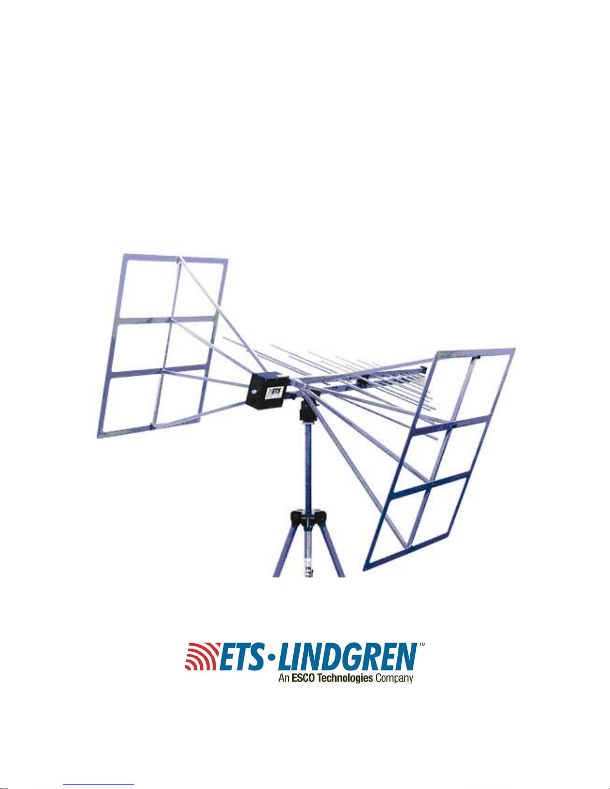
Model 3142C
Archived 01/19/11
BiConiLog™ Antenna
User Manual
Page 2
ETS-Lindgren L.P. reserves the right to make changes to any products herein to improve
Archived 01/19/11
functioning or design. Although the information in this document has been carefully reviewed and
is believed to be reliable, ETS-Lindgren does not assume any liability arising out of the
application or use of any product or circuit described herein; nor does it convey any license under
its patent rights nor the rights of others. All trademarks are the property of their respective
owners.
©Copyright 2000–2006 by ETS-Lindgren L.P. All Rights Reserved. No part of this
document may be copied by any means without written permission from
ETS-Lindgren L.P.
Trademarks used in this document: The ETS-Lindgren logo and BiConiLog are trademarks of
ETS-Lindgren L.P.
Revision Record | MANUAL MODEL 3142, Part # 399229, Rev. E
Revision Description Date
A Initial Release November, 2000
B Update to new format, add Model 3141
information
C Edit/update February, 2003
D Edit/update June, 2003
E Update bowtie/antenna knob information November, 2006
Internet Address
http://www.ETS-Lindgren.com
USA
1301 Arrow Point Drive
Cedar Park, TX 78613 USA
Tel: +1.512.531.6400
Fax: +1.512.531.6500
Email: info@ETS-Lindgren.com
Japan
4-2-6, Kohinata
Bunkyo-ku, Tokyo 112-0006 Japan
Tel: +81.3.3813.7100
Fax: +81.3.3813.8068
Email: info@ETS-Lindgren.co.jp
Finland
Mekaanikontie 1, 27510
Eura, Finland
Tel: +358.2.838.330
Fax: +358.2.865.1233
Email: info@ETS-Lindgren.eu.com
China
B507A Technology Fortune Center
No. 8 Xue Qing Road
Haidian District
Beijing Postcode: 100083 China
Tel: +86.010.827.30877
Fax: +86.010.827.55307
Email: info@ETS-Lindgren.net
January, 2001
ii |
Page 3

Table of Contents
Archived 01/19/11
Safety Symbol Definitions ................................................................................................................. v
General Safety Considerations ......................................................................................................... v
1.0 Introduction ................................................................................................................................ 7
2.0 Receiving Your Order ................................................................................................................ 9
2.1 Unpacking and Acceptance ................................................................................................... 9
2.2 Return Procedures ................................................................................................................. 9
3.0 Maintenance ............................................................................................................................ 11
4.0 Mounting Instructions .............................................................................................................. 13
4.1 Model 3142C Components .................................................................................................. 13
4.2 Mount the Bow-tie Elements ................................................................................................ 13
4.3 Connect the Optional End Plates to Create the T Bow-ties ................................................. 14
5.0 Application ............................................................................................................................... 17
5.1 Without Optional End Plates ................................................................................................ 17
5.2 With Optional End Plates ..................................................................................................... 18
6.0 Typical Data Without Optional End Plates .............................................................................. 19
6.1 Model 3142C Typical 26-3000 MHz VSWR ......................................................................... 19
6.2 Model 3142C Typical 26-3000 MHz Antenna Factor ........................................................... 19
6.3 Model 3142C Typical 26-3000 MHz Gain ............................................................................ 20
7.0 Typical Data with Optional End Plates .................................................................................... 21
7.1 Model 3142C Typical 26-3000 VSWR ................................................................................. 21
7.2 Model 3142C Typical 26-3000 MHz Antenna Factor ........................................................... 22
7.3 Model 3142C Typical 26-3000 MHz 1M Forward Power ..................................................... 23
7.4 Model 3142C Typical 26-3000 MHz 3M Forward Power ..................................................... 24
8.0 Specifications .......................................................................................................................... 25
8.1 Electrical Specifications ....................................................................................................... 25
8.2 Physical Specifications ........................................................................................................ 25
9.0 Warranty Policy for Standard EMCO Brand Products ............................................................. 27
9.1 Scope and Duration of Warranties ....................................................................................... 27
9.2 Warranty Exclusions ............................................................................................................ 27
9.3 Buyer’s Remedies ................................................................................................................ 28
| iii
Page 4

This page intentionally left blank.
Archived 01/19/11
iv |
Page 5
Safety Symbol Definitions
Archived 01/19/11
This product and related documentation must be reviewed for familiarization with
safety markings and instructions prior to operation of the product.
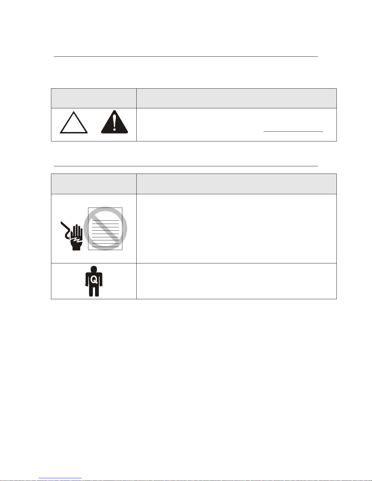
Safety Symbol Definition
REFER TO MANUAL—When the product is marked with this symbol
refer to the instruction manual for additional information. If the
!
OR
instruction manual has been misplaced, go to www.ets-lindgren.com
downloadable files or contact ETS-Lindgren customer service.
General Safety Considerations
Safety Symbol Definition
BEFORE SERVICING: CONTACT ETS-LINDGREN
(+1.512.531.6400)—Servicing or modifying the unit without
WARRAN TY
ETS-Lindgren authorization may void your warranty. If an attempt to
service the unit must be made, disconnect all electrical power prior to
beginning. Voltages exist at many points within the instrument that
could, if contacted, cause personal injury. Only trained service
personnel should perform adjustments and/or service procedures upon
this instrument. Capacitors inside this instrument may still be charged
even when the instrument is disconnected from the power source.
for
ONLY QUALIFIED PERSONNEL should operate or service this
equipment.
| v
Page 6

This page intentionally left blank.
Archived 01/19/11
vi |
Page 7

Archived 01/19/11
1.0 Introduction
The ETS-Lindgren Model 3142C BiConiLog™ Antenna is designed as a dualpurpose antenna that can be used for both emissions and immunity applications.
The Model 3142C is a hybrid linearly polarized EMC antenna consisting of a
log-periodic dipole array (LPDA) and a single bow-tie antenna. Historically,
bow-ties have been used for all elements on log-periodic antennas, and in EMC
applications the advantage is an extension of the useful low frequency range of
the typical LPDAs from 100 MHz to 30 MHz. At 30 MHz, an efficient single dipole
type antenna must be five meters long, but a suitable performance is obtained
with a bow-tie that is 1.7-meter long.
A simple wire outline bow-tie antenna is narrowband compared to a sheet
bow-tie or biconical, so struts are added to the Model 3142C bow-ties to better
simulate the broadband sheet bow-tie. The standard self-balun feed of the
log-periodic also provides a matched, balanced feed to the bow-tie elements.
Below 150 MHz, bow-tie radiation dominates with a dipole-like pattern, and
above 150 MHz the radiation in the plane of the elements is directional.
To prevent cable pickup below 100 MHz, the Model 3142C contains a balun that
acts as a common-mode choke to keep unbalanced current off the coaxial feed
cable outer shield. Though the Model 3142C is highly balanced, in vertically
polarized measurements cable position can effect results, so it is recommended
that the cable be suspended horizontally back from the antenna at least one
meter before any vertical drop.
The antenna has a mounting bracket and ¼-20 UNC thread knob to attach to an
ETS-Lindgren tripod or tower adapter. Individual antenna factors and gain
calibration data is included with each antenna.
The Model 3142C optional end plates (part #106572) are available to improve
gain for immunity testing. This option consists of two end plates that are easily
attached and detached by hand using captive screw knobs. When the end plates
are attached it creates a T-shaped bow-tie element.
For any dipole-type antenna to transmit or receive energy most efficiently, its
length must be nearly a half wavelength, which is about 4.6 meters long at
30 MHz, and 2.8 meters long at 50 MHz. Unfortunately, this is too unwieldy for
many anechoic chambers and test sites. The optional end plates of the Model
3142C make it appear like an antenna twice as long as its 1.4 meter length. The
result is approximately a 10 dB improvement in low frequency transmit gain and
receive antenna factor compared to a same length regular bow-tie.
Introduction | 7
Page 8

Archived 01/19/11
With the end plates attached to the Model 3142C bow-tie elements, the
equivalent dipole electrical length is increased, which decreases resonant
frequency and increases efficiency in the 20 to 60 MHz range. Similarly, the
regular bow-tie has a lower resonant frequency than an equal length single-wire
dipole. The T end plate option has its first resonance at a frequency where its
length is about 0.22 λ, a regular bow-tie at a length of 0.3 λ, and a tuned dipole at
about a length of 0.48 λ. Thus, at 50 MHz the 1.4-meter long end plate option
behaves as if a 2.8 meter tuned dipole. Cross-polar radiation is minimized
because current flow on one of the T end frames is almost completely cancelled
by the opposite-phased current on the other T end.
8 | Introduction
Page 9

Archived 01/19/11
2.0 Receiving Your Order
2.1 Unpacking and Acceptance
Step 1. Upon delivery of your order, inspect the shipping container(s) for
evidence of damage. Record any damage on the delivery receipt before signing
it. In case of concealed damage or loss, retain the packing materials for
inspection by the carrier.
Step 2. Remove the product from its shipping container(s). Save the container(s)
and any protective packing materials for future use.
Step 3. Check all materials against the packing list to verify that the equipment
you received matches what was ordered. If you find any discrepancies, note
them and call ETS-Lindgren Customer Service for further instructions.
Ensure that you are satisfied with the contents and condition of your order prior
to placing the product into service.
2.2 Return Procedures
To return a system or system component:
Step 1. Contact ETS-Lindgren Customer Service to obtain an SRO, Service
Request Order.
Step 2. Briefly describe the problem in writing. Give details regarding the
observed symptom(s) or error codes, and whether the problem is constant or
intermittent in nature. Please include the date(s), the service representative you
spoke with, and the nature of the conversation. Include the serial number of the
item being returned.
Step 3. Package the system or component carefully. If possible, use the original
packing materials to return a system or system component to ETS-Lindgren at
the following address:
ETS-Lindgren
Attn. Service Department
301 Arrow Point Drive
Cedar Park, TX, USA 78613
Phone: +1.512.531.6400
Receiving Your Order | 9
Page 10

Archived 01/19/11
This page intentionally left blank.
10 | Receiving Your Order
Page 11

Archived 01/19/11
3.0 Maintenance
To ensure reliable and repeatable long-term performance, annual recalibration of
your antenna by ETS-Lindgren’s experienced technicians is recommended. Our
staff can recalibrate almost any type or brand of antenna. Please call to receive a
Service Order Number prior to sending an antenna to us for calibration.
For more information about our calibration services, visit our website at
http://www.ETS-Lindgren.com
.
Maintenance | 11
Page 12

Archived 01/19/11
This page intentionally left blank.
12 | Maintenance
Page 13

Archived 01/19/11
4.0 Mounting Instructions
4.1 Model 3142C Components
The Model 3142C BiConiLog™ Antenna consists of the following:
• (1) Antenna
• (2) Bow-tie elements
• (2) 10-32 thread knobs to attach bow-tie elements
• (2) Protective end caps for bow-tie elements
• (8) Screws to attach protective end caps to bow-tie elements
The optional end plate package consists of:
• (2) T bow-tie endplates
• (8) Thumbscrew knobs to attach endplates to bow-tie elements
4.2 Mount the Bow-tie Elements
1. Without the bow-tie elements attached, mount the Model 3142C on a
tripod or tower adapter.
2. Slide the narrow end of one of the bow-tie elements into the receptacle
hole on the boom, and then align the bow-tie with the receptacle on the
boom.
Figure 1: Bow-tie element mounted to boom
Mounting Instructions | 13
Page 14

Archived 01/19/11
3. Insert one of the 10-32 thread knobs into the opposite side of the boom
from where you inserted the bow-tie. Slowly tighten the knob, taking care
not to cross-thread the connection. Cross-threading the connection could
cause permanent damage to the bow-tie element.
4. Repeat steps 2 and 3 for the second bow-tie element.
4.3 Connect the Optional End Plates to Create the T Bow-ties
1. For protection, there is a black end cap on each of the bow-tie elements.
Use a Phillips head screwdriver to carefully remove the four screws in
each of the bow-tie end caps.
The end caps should be reinstalled when you are done using the
optional end plates, so store the end caps and the screws in a safe
place.
2. Align the four holes on the wide end of the bow-tie element with the four
holes on the end plate. Insert each of the four small knobs in the
receptacle holes and slowly tighten. Be careful not to cross-thread the
connection or permanent damage to the bow-tie could occur.
3. Repeat step 2 for the remaining end plate.
14 | Mounting Instructions
Figure 2: Bow-tie element receptacle hole and
optional end plate with screw knob
Page 15

Archived 01/19/11
Contact with any metal or non-metallic structure can capacitively load the
antenna, which may cause unrepeatable results. Therefore, make sure that no
part of the dipole elements or bow-ties is in contact with the tripod or tower,
particularly in vertically-polarized tests. Where possible, run the feed cable
straight one meter or more back from the Model 3142C before dropping
vertically.
Both horizontal and vertical polarization is easily accomplished when the
Model 3142C with the optional end plates is mounted on a tower, but vertical
polarization on a tripod requires special consideration. Because immunity power
requirements are many dB lower for vertical polarization, the T end frames can
be removed when mounting vertically on a standard tripod. A special tripod is
available from ETS-Lindgren for vertical polarization with T bow-ties intact.
Please contact ETS-Lindgren for the recommended mounting scheme.
Mounting Instructions | 15
Page 16

Archived 01/19/11
This page intentionally left blank.
16 | Mounting Instructions
Page 17

f
Archived 01/19/11
5.0 Application
5.1 Without Optional End Plates
For emissions measurements, electric fields strength in dB[V/m] is obtained from:
α
E(dB[V/m]) = V(dB[V]+AF(dB[1/m])+
V = the receiver or spectrum analyzer voltage reading
AF = antenna factor
α
= cable loss, if cable losses are non-negligible
For immunity testing, the electrical field strength generated at a distance d can
be approximated by:
Pg
E
V/m =
()
30
d
(dB)
d = distance, in meters
g = numeric gain (10
P = antenna net input power, in watts
An estimate of the power required for any field strength E can be obtained from
Model 3142C Typical 1 V/m Power Required on page Error! Bookmark not
defined.Error! Bookmark not defined.Error! Bookmark not defined., which
shows power required in watts to generate 1 V/m. Power shown is calculated
from the measured gain and corrected for VSWR. For any other field strength,
multiply the power in watts by desired E-field squared, or:
Actual transmitted field strength should be verified using an ETS-Lindgren
electric field probe, or an equivalent. A
VSWR into account, is obtained from:
P
= Pn / {1-[(VSWR-1)/(VSWR+1)]2}
f
P
= forward (amplifier output) power
G[dB]/10
)
P(E V/m) = E
n estimate of the power required, taking
2
P(1 V/m)
P
= new power as discussed
n
Application | 17
Page 18

()(
Archived 01/19/11
For IEC 1000-4-3 type testing, the antenna tip can be placed at any distance
between one and three meters from the EUT as long as the front face plane is
illuminated according to the –0,+6 dB specification.
5.2 With Optional End Plates
For emissions testing it is recommended that the Model 3142C be used without
the optional end plates. The coupling of the endplates to ground will create
higher uncertainty values, particularly in the vertical polarization.
For more information about this issue, see “Understanding the
Measurement Uncertainties of the Bicon/log Hybrid Antennas” by
Zhong Chen in the 1999 issue of the International Journal of EMC
For immunity testing, the electric field strength generated at a distance d can be
approximated by the formula:
.
E
V/m =
()
d = distance, in meters
g = numeric gain (10
P = antenna net input power, in watts
An estimate of the power required for any field strength E can be obtained from
Model 3142C Typical 26-3000 MHz 1M Forward Power on page 23 or Model
3142C Typical 26-3000 MHz 3M Forward Power on page 24, which shows power
required in watts to generate 1 V/m. For any other field strength not shown,
multiply the power in watts by the desired E-field squared, or
Actual transmitted field strength should be verified using an ETS-Lindgren
electric field probe, or an equivalent. For IEC 1000-4-3 type testing, the antenna
tip can be placed at any distance between one and three meters from the EUT as
long as the front face plane is illuminated according to the –0,+6 dB specification.
In general, closer distances require less power to create a given field strength.
PE E PV/m V/m=
30
G[dB]/10
Pg
d
)
2
1
)
18 | Application
Page 19

0
)
Archived 01/19/11
6.0 Typical Data Without Optional End Plates
6.1 Model 3142C Typical 26-3000 MHz VSWR
100
10
WR
S
V
1
20 100 1000 300
Frequency (MHZ
6.2 Model 3142C Typical 26-3000 MHz Antenna Factor
Distance for the ANSI 3 and 10 meter calibrations is measured from the antenna
midpoint, and for SAE 1 meter calibrations the distance is measured from the
antenna tip. Midpoint is defined as half the distance between the small elements
and the bow-ties, which is about 45 cm from the small end tip.
45
40
35
30
25
dB 1/m
20
1m
15
3m
10
10m
5
20 100 1000 3000
Frequency (MHZ)
Typical Data Without Optional End Plates | 19
Page 20

)
d
B
Archived 01/19/11
6.3 Model 3142C Typical 26-3000 MHz Gain
This data is derived from the 3 antenna method antenna factors.
10
5
0
-5
1m
-10
-15
-20
-25
20 100 1000 3000
Frequency (Mz
H
3m
10m
20 | Typical Data Without Optional End Plates
Page 21

Archived 01/19/11
7.0 Typical Data with Optional End Plates
The power shown was measured over a ground plane with 1.5 meters transmit
antenna and probe height, horizontal polarization. Horizontal polarization is the
worst-case power required; typically less power is required for vertical
polarization. In practice, many users place ferrite tiles on the ground between the
antenna and probe to reduce reflected-ray interference. For any other field
strength E, multiply the power in watts for 1 V/m by E
7.1 Model 3142C Typical 26-3000 VSWR
10
2
.
1
20
100 1000
3000
Frequency MHz
Typical Data with Optional End Plates | 21
Page 22

m
Archived 01/19/11
7.2 Model 3142C Typical 26-3000 MHz Antenna Factor
Distance for the ANSI 3 meter and 10 meter calibrations is measured from the
antenna midpoint, and for SAE 1 meter calibrations the distance is measured
from the antenna tip. Midpoint is defined as half the distance between the small
elements and the bow-ties, which is about 45 cm from the small end tip.
45
40
35
30
25
dB 1/
20
15
3m
10m
10
5
20 100 1000 3000
Frequency (M z)H
1m
22 | Typical Data with Optional End Plates
Page 23

Archived 01/19/11
7.3 Model 3142C Typical 26-3000 MHz 1M Forward Power
The following illustrates the typical 26-3000 MHz forward power required for 1, 3,
and 10 V/m at 1 meter from the tip of the antenna.
1000
100
10
1
Watts
0.1
0.01
100 1000
1V/m
80% AM
3V/m
80% AM
10 V/m
80% AM
300020
Frequency MHz
Typical Data with Optional End Plates | 23
Page 24

Archived 01/19/11
7.4 Model 3142C Typical 26-3000 MHz 3M Forward Power
The following illustrates the typical 26-3000 MHz forward power required for 1, 3,
and 10 V/m at 3 meters from the antenna tip.
1V/m
80% AM
3V/m
80% AM
10 V/m
80% AM
Watts
1000
100
10
1
0.1
0.01
20
100 1000
Frequency MHz
3000
24 | Typical Data with Optional End Plates
Page 25

Archived 01/19/11
8.0 Specifications
8.1 Electrical Specifications
Frequency Range:
Input Impedance
VSWR:
CW power:
Symmetry:
Connector:
8.2 Physical Specifications
Height (bow-tie):
With Standard Bow-tie
Elements
26-3000 MHz 26-3000 MHz
50 Ω 50 Ω
2:1 average 2:1 average
26 MHz – 60 MHz500 W60
MHz – 600 MHz1kW600
MHz – 1GHz750W1 GHz –
3 GHz500 W
+/- 0.5 dB +/- 0.5 dB
N female N female
With Standard Bow-tie
Elements
75 cm
29.5 in
With Optional End Plates
26 MHz – 60 MHz500 W60
MHz – 600 MHz1kW600
MHz – 1GHz750W1 GHz –
3 GHz500 W
With Optional End Plates
75 cm
29.5 in
Width (bow-tie):
Depth (boom length):
Weight:
135 cm
53.1 in
90 cm
35.4 in
4 kg
8.8 lb
136 cm
53.5 in
132 cm
51.9 in
6.8 kg
14.9 lb
Specifications | 25
Page 26

Archived 01/19/11
This page intentionally left blank.
26 | Specifications
Page 27

Archived 01/19/11
9.0 Warranty Policy for Standard EMCO Brand Products
9.1 Scope and Duration of Warranties
Seller warrants to Buyer that the Standard EMCO Brand Products Excluding
5211 & 5220 be (1) free from defects in material, manufacturing workmanship,
and title, and (2) conform to the Seller’s applicable product descriptions and
specifications, if any, contained in or attached to Seller’s quotation. If no product
descriptions or specifications are contained in or attached to the quotation,
Seller’s applicable product descriptions and specifications in effect on the date of
shipment shall apply. The criteria for all testing shall be Seller’s applicable
product specifications utilizing factory-specified calibration and test procedures
and instruments.
All product warranties, except the warranty of title, and all remedies for warranty
failures are limited in time as shown in the following table.
Product Warranted Duration of Warranty Period
Standard EMCO Brand Products
Excluding 5211 & 5220
Any product or part furnished to Buyer during the warranty period to correct a
warranty failure shall be warranted to the extent of the unexpired term of the
warranty applicable to the repaired or replaced product.
The warranty period shall commence on the date the product is delivered to
Buyer; however, if Seller assembles the product, or provides technical direction
of such assembly, the warranty period for such product shall commence on the
date the assembly of the product is complete. Notwithstanding the foregoing, in
the event that the assembly is delayed for a total of thirty (30) days or more from
the date of delivery for any reason or reasons for which Seller is not responsible,
the warranty period for such product may, at Seller’s options, commence on the
thirtieth (30th) day from the date such product is delivered to Buyer. Buyer shall
promptly inspect all products upon delivery. No claims for shortages will be
allowed unless shortages are reported to Seller in writing within ten (10) days
after delivery. No other claims against Seller will be allowed unless asserted in
writing within thirty (30) days after delivery (or assembly if the products are to be
assembled by Seller) or, in the case of alleged breach of warranty, within the
applicable warranty period.
2 Years
9.2 Warranty Exclusions
Except as set forth in any applicable patent indemnity, the foregoing warranties
are exclusive and in lieu of all other warranties, whether written, oral, express,
implied, or statutory. EXCEPT AS EXPRESSLY STATED ABOVE, SELLER
MAKES NO WARRANTY, EXPRESS OR IMPLIED, BY STATUTE OR
Warranty Policy for Standard EMCO Brand Products | 27
Page 28

Archived 01/19/11
OTHERWISE, WHETHER OF MERCHANTABILITY OR FITNESS FOR ANY
PARTICULAR PURPOSE OR USE OR OTHERWISE ON THE PRODUCTS, OR
ON ANY PARTS OR LABOR FURNISHED DURING THE SALE, DELIVERY OR
SERVICING OF THE PRODUCTS. THERE ARE NO WARRANTIES WHICH
EXTEND BEYOND THE DESCRIPTION ON THE FACE HEREOF.
Warranty coverage does not include any defect or performance deficiency
(including failure to conform to product descriptions or specifications) which
results, in whole or in part, from (1) negligent storage or handling of the product
by Buyer, its employees, agents, or contractors, (2) failure of Buyer to prepare
the site or provide an operating environmental condition in compliance with any
applicable instructions or recommendations of Seller, (3) absence of any product,
component, or accessory recommended by Seller but omitted at Buyer’s
direction, (4) any design, specification, or instruction furnished by Buyer, its
employees, agents or contractors, (5) any alteration of the product by persons
other than Seller, (6) combining Seller’s product with any product furnished by
others, (7) combining incompatible products of Seller, (8) interference with the
radio frequency fields due to conditions or causes outside the product as
furnished by Seller, (9) improper or extraordinary use of the product, or failure to
comply with any applicable instructions or recommendations of Seller, or (10)
acts of God, acts of civil or military authority, fires, floods, strikes or other labor
disturbances, war, riot, or any other causes beyond the reasonable control of
Seller. This warranty does not cover (1) contact fingers or replacements unless
loss is caused by a defect in material or manufacturing workmanship within the
scope of this warranty (2) items designed to be consumable and (3) removal and
reconstruction of walls, partitions, ceilings and other facility costs arising from
repair or replacement of the product or parts thereof by Seller under the
warranty. Seller does not warranty products of others which are not included in
Seller’s published price lists for shielding products and systems supplies and
accessories.
9.3 Buyer’s Remedies
If Seller determines that any product fails to meet any warranty during the
applicable warranty period, Seller shall correct any such failure by either, at its
option, repairing, adjusting, or replacing without charge to Buyer any defective or
nonconforming product, or part or parts of the product. Seller shall have the
option to furnish either new or exchange replacement parts or assemblies.
Warranty service during the applicable warranty period will be performed without
charge to Buyer within the contiguous 48 United States during Seller’s normal
business hours. After the warranty period, service will be performed at Seller’s
prevailing service rates. Subject to the availability of personnel, after-hours
service is available upon request at an additional charge. For service outside the
contiguous 48 United States, travel and per diem expenses, when required, shall
be the responsibility of the Buyer, or End User, whichever is applicable.
28 | Warranty Policy for Standard EMCO Brand Products
Page 29

Archived 01/19/11
The remedies set forth herein are conditioned upon Buyer promptly notifying
Seller within the applicable warranty period of any defect or nonconformance and
making the product available for correction.
The preceding paragraphs set forth Buyer’s exclusive remedies and Seller’s sole
liability for claims based on failure of the products to meet any warranty, whether
the claim is in contract, warranty, tort (including negligence and strict liability) or
otherwise, and however instituted, and, upon the expiration of the applicable
warranty period, all such liability shall terminate. IN NO EVENT SHALL SELLER
BE LIABLE TO BUYER FOR ANY SPECIAL INDIRECT, INCIDENTAL OR
CONSEQUENTIAL DAMAGES OF ANY KIND ARISING OUT OF, OR AS A
RESULT OF, THE SALE, DELIVERY, NON-DELIVERY, SERVICING,
ASSEMBLING, USE OR LOSS OF USE OF THE PRODUCTS OR ANY PART
THEREOF, OR FOR ANY CHARGES OR EXPENSES OF ANY NATURE
INCURRED WITHOUT SELLER’S WRITTEN CONSENT DESPITE ANY
NEGLIGENCE ON BEHALF OF THE SELLER. IN NO EVENT SHALL SELLER’S
LIABILITIES UNDER ANY CLAIM MADE BY BUYER EXCEED THE
PURCHASE PRICE OF THE PRODUCT IN RESPECT OF WHICH DAMAGES
ARE CLAIMED. This agreement shall be construed in accordance with laws of
the State of Illinois. In the event that any provision hereof shall violate any
applicable statute, ordinance, or rule of law, such provision shall be ineffective to
the extent of such violation without invalidating any other provision hereof.
Any controversy or claim arising out of or relating to the sale, delivery,
nondelivery, servicing, assembling, use or loss of use of the products or any part
thereof or for any charges or expenses in connection therewith shall be settled in
Austin, Texas by arbitration in accordance with the Rules of the American
Arbitration Association, and judgment upon the award rendered by the Arbitrator
may be entered in either the Federal District Court for the Western District of
Texas or the State District Court in Austin, Texas, all of the parties hereto
consenting to personal jurisdiction of the venue of such court and hereby waive
the right to demand a jury trial under any of these actions.
Warranty Policy for Standard EMCO Brand Products | 29
 Loading...