

Page 1
Archived 6/1/10
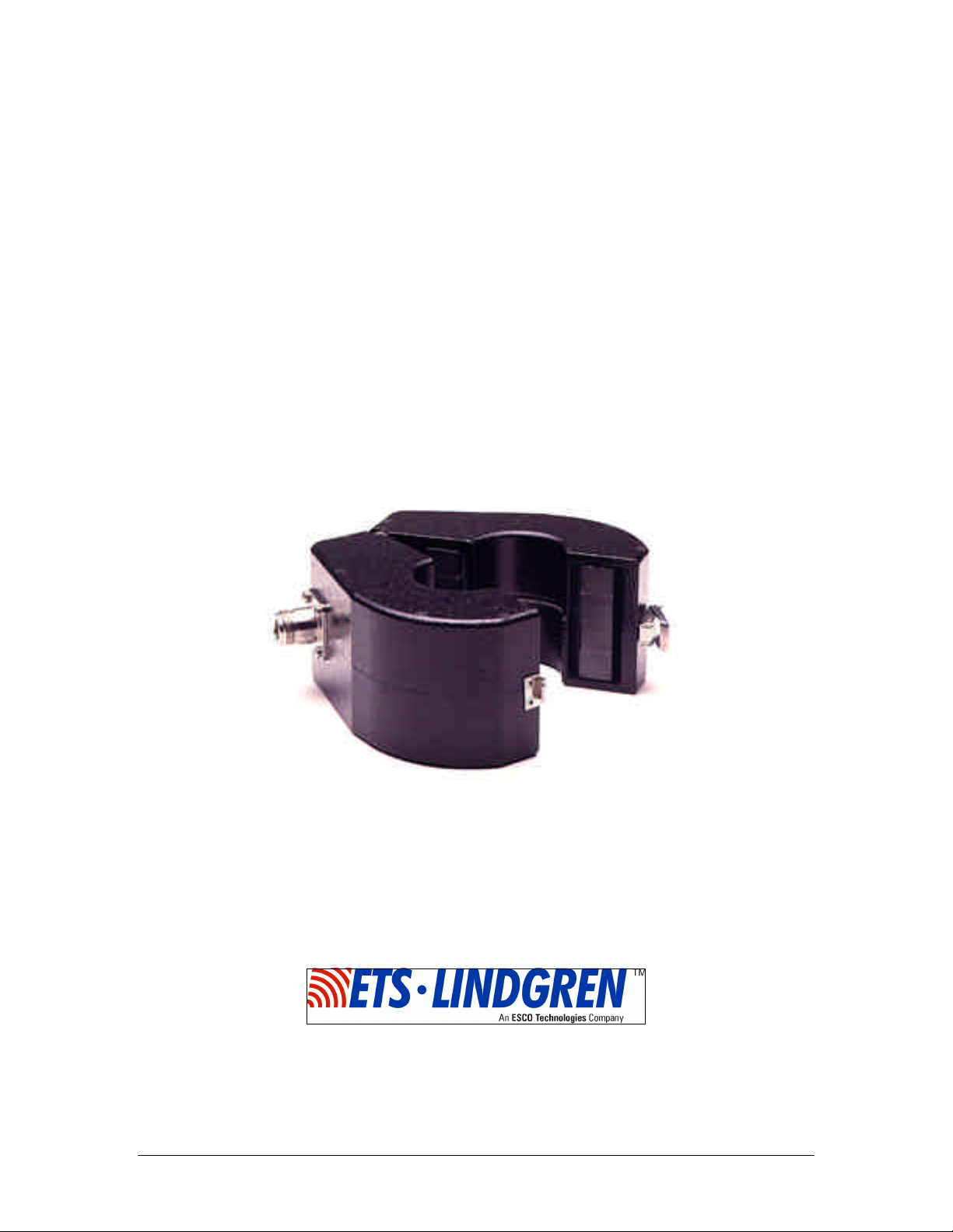
Bulk Current
Injection Probes
MANUAL
© ETS-Lindgren, L.P. – February 2005 Rev C – PN 399263
95236-1 95242-1 95252-1
Page 2

BULK CURRENT INJECTION PROBES
Archived 6/1/10
ETS-Lindgren L.P. reserves the right to make changes to any products herein to improve functioning,
design, or for any other reason. Nothing contained herein shall constitute ETS-Lindgren L.P. assuming any
liability whatsoever arising out of the application or use of any product or circuit described herein.
ETS-Lindgren L.P. does not convey any license under its patent rights or the rights of others.
© Copyright 2005 by ETS-Lindgren L.P. All Rights Reserved.
No part of this document may be copied by any means
without written permission from ETS-Lindgren L.P.
E-MAIL & INTERNET
Support@ets-lindgren.com
http://www.ets-lindgren.com
USA
1301 Arrow Point Dr., Cedar Park, TX 78613
P.O. Box 80589, Austin, TX 78708-0589
Phone 512.531.6400
Fax 512.531.6500
FINLAND
Euroshield OY
Mekaanikontie 1
27510, Eura, Finland
Phone + 358.2.838.3300
Fax + 358.2.865.1233
JAPAN
4-2-6, Kohinata
Bunkyo-ku
Tokyo 112-0006
JAPAN
Phone + 81 3 3813 7100
Fax + 81 3 3813 8068
CHINA
1917-1918 Xue Zhixuan Building
No 16 Xue Qing Road
Haidian District
Beijing Postcode: 100083
CHINA
Phone + 86 010 82755304
Fax + 86 010 82755307
© ETS-Lindgren, L.P. – February 2005
Rev C – PN 399263
Page 3

BULK CURRENT INJECTION PROBES
Archived 6/1/10
Table of Contents
INTRODUCTION............................................................................................................. 1
APPLICATION................................................................................................................. 2
CONDUCTED SUSCEPTIBILITY ..........................................................................................2
TEST SETUP APPARATUS.................................................................................................. 4
CONDUCTED EMISSION.............................................................................................. 7
TRANSFER IMPEDANCE (ZT)............................................................................................. 7
INSERTION LOSS......................................................................................................... 10
EQUIPMENT.................................................................................................................... 10
PROCEDURE ...................................................................................................................11
PRECAUTIONARY MEASURES................................................................................ 12
SPECIFICATIONS......................................................................................................... 13
SUPPORTING EQUIPMENT....................................................................................... 16
MAINTENANCE............................................................................................................ 17
WARRANTY STATEMENT ........................................................................................ 18
© ETS-Lindgren, L.P. – February 2005
Rev C – PN 399263
Page 4

BULK CURRENT INJECTION PROBES
Archived 6/1/10
© ETS-Lindgren, L.P. – February 2005
Rev C – PN 399263
Page 5

BULK CURRENT INJECTION PROBES Introduction
Archived 6/1/10
INTRODUCTION
The ETS-Lindgren Bulk Current Injection Probe series is used to
inject RF current into conductors and cables of electrical and
electronic equipment undergoing susceptibility testing.
The Bulk Current Injection Probe provides a means of applying a
controlled RF stress level to an instrument under test (IUT)
through interconnecting cables or power cables without requiring a
direct connection to the conductor(s) of interest. The models in
this series are simply clamped around the test conductor which
then becomes a one turn secondary winding, with the current probe
forming the core and primary winding of an RF transformer. RF
energy can be injected onto single and multi-conductor cables,
grounding and bonding straps, outer conductors of shielding
conduits and coaxial cables, etc.
The bulk current injection probe series is especially designed to
provide minimum insertion loss over the following frequency
ranges:
Model Number Frequency Range Useful Range
95236-1 0.1 to 10 MHz 0.01 to 100 MHz
95242-1 2 to 400 MHz 2 to 400 MHz
95252-1 450 to 900 MHz 20 to 1000 MHz
Table 1
Because of the high efficiency design, the injection probes can also
© ETS-Lindgren, L.P. – February 2005 1
Rev C – PN 399263
be used as very sensitive sensors.
Page 6

Application BULK CURRENT INJECTION PROBES
Archived 6/1/10
APPLICATION
The principal use of the bulk current injection probe is for inducing
relatively large RF currents into the signal and power circuits of
equipment under test for conducted susceptibility. A secondary
application would be to use the same probe in a more familiar role
as a sensor for measuring weak conducted RF currents.
CONDUCTED SUSCEPTIBILITY
Conducted susceptibility testing is intended to insure that RF
signals, when coupled on to interconnecting cables and power
supply lines of an IUT, will not cause malfunction or degradation
of performance. In addition, this testing can provide an amplitude
vs. frequency malfunction signature for the system which, when
compared with the levels of current on the cables in a typical
operating environment, can assist in the determination of adequate
safety margins.
TYPICAL TEST SETUP
Typical conducted susceptibility tests require that all power and
interconnecting cables be tested by subjecting them to the required
current or voltage levels, while monitoring the applied current
using a current probe. Usually, a reference level calibration is
performed using a calibration jig with a specified impedance. This
reference curve is then replayed to expose the IUT to a controlled
stress level, while a current probe is used to insure that a low
2 © ETS-Lindgren, L.P. – February 2005
Rev C – PN 399263
impedance IUT is not overstressed.
Note: Some tests may allow the reference calibration to be
performed at a lower level and then scaled up to the required
power level when applied to the IUT.
Page 7

BULK CURRENT INJECTION PROBES Application
Archived 6/1/10
Entire cables or cable bundles may be tested, or each line may be
broken out and tested individually. Some standards may also
require simultaneous injection onto multiple cable bundles using
several injection probes. Absorbing clamps may be required to
isolate peripheral equipment from the IUT, and insure that only the
IUT is exposed to the required stress level. Refer to the pertinent
test standard for more specific details.
© ETS-Lindgren, L.P. – February 2005 3
Rev C – PN 399263
Page 8

Application BULK CURRENT INJECTION PROBES
Archived 6/1/10
TEST SETUP APPARATUS
The following equipment may be needed to set up the test
environment:
§ Current Injection Probes:
95236-1 (0.1 to 10 MHz)
95242-1 (2 to 400 MHz)
95252-1 (400 to 1000 MHz)
§ Calibration Jig 95241-1
For the current injection probes. When using the Model
95252-1 the Model 95251-1 Calibration Jig is
recommended. It is the same as the Model 95241-1 Jig
listed above except that it has been modified to proved
better high frequency characteristics for the Model
95252-1 injection probe.
§ Current Monitoring Probes
§ Signal Source/Generator
§ Power amplifier(s)
The power amplifier should be capable of supplying the
full rated power into the current injection probes (which
have a high VSWR) with a low harmonic content.
§ Spectrum analyzer or measuring receivers
§ Directional coupler
§ RF Voltmeter(s)
§ RF Absorbing Clamp
§ RF Attenuator
§ RF Loads
4 © ETS-Lindgren, L.P. – February 2005
Rev C – PN 399263
Page 9

BULK CURRENT INJECTION PROBES Application
Injection
Calibration
50
Attenuator
Current Level
50 Load
(typical)
Archived 6/1/10
Ω
Signal
Generator
Amplifier
Directional
Coupler
Probe
Fixture
RF Voltmeter
for T
x
Voltage Level
Test Dependant
Equipment
Ω
RF Voltmeter
for Injected
Figure 1—Sample Conducted Susceptibility Calibration Setup
© ETS-Lindgren, L.P. – February 2005 5
Rev C – PN 399263
Page 10

Application BULK CURRENT INJECTION PROBES
RF
Peripheral
Equiptment
Optional
Absorbing
RF
Voltmeter
Injection
Archived 6/1/10
Signal
Generator
Test Dependant
Equipment
Current
Probe
Voltmeter
Instrument
Under Test
Probe
Clamp
Figure 2—Sample Conducted Susceptibility Test Setup
6 © ETS-Lindgren, L.P. – February 2005
Rev C – PN 399263
Page 11

BULK CURRENT INJECTION PROBES Conducted Emission
Archived 6/1/10
CONDUCTED EMISSION
TRANSFER IMPEDANCE (ZT)
The current injection probe may also be used as a sensor for
measuring conducted emission. The RF current ((IP) in
microamperes) in the conductor under test is determined from the
measuring receiver reading of the probe output (in microvolts (ES))
divided by the probe transfer impedance ((ZT ) in ohms).
IP=ES/ZT
Or in dB,
IP(dBµA) = ES(dBµV) – ZT(dB)
The transfer impedance is determined by passing a known RF
current (IP) through the primary test conductor and noting the
voltage (ES) developed across a 50 Ohm load on the probe output.
ZT = ES/IP
© ETS-Lindgren, L.P. – February 2005 7
Rev C – PN 399263
Page 12

Conducted Emission BULK CURRENT INJECTION PROBES
Archived 6/1/10
Calibration Jig 95241-1 may be used for this determination.
Typical transfer impedance values for the Model 95242-1 Probe
when used as a sensor are:
Frequency
(MHz)
ZT
(Ω)
2 7
4 14
6 21
8 26
10 30
15 35
20 37
30 38
40 39
50 39.5
60 40
80 41
100 41
140 42
180 42
220 43
260 43
300 43
320 43.5
340 43.6
360 44
380 42.5
400 39
420 32
440 25
460 17
Table 2
High sensitivity and minimal core gap indicate that the current
8 © ETS-Lindgren, L.P. – February 2005
Rev C – PN 399263
probe should be used only on signal lines where heavy currents are
not encountered. Heavy currents may affect measurement
accuracy should current probe core saturation occur.
Page 13

BULK CURRENT INJECTION PROBES Conducted Emission
Archived 6/1/10
Typical transfer impedance values for the Model 95252-1 when
used as a sensor are:
Frequency
(MHz)
400 25
450 16
500 20
550 22
600 22
650 20
700 19
750 18
800 15
850 11
900 8
950 5.7
1000 3.7
Table 3
Z
T
(Ω)
© ETS-Lindgren, L.P. – February 2005 9
Rev C – PN 399263
Page 14

Insertion Loss BULK CURRENT INJECTION PROBES
Archived 6/1/10
INSERTION LOSS
Insertion loss of the 94242-1 Bulk Current Injection Probe may be
measured at low signal levels. ETS-Lindgren offers this
measurement as a calibration service, please contact our calibration
department for more information.
EQUIPMENT
Signal Generator (50 Ohms)
RF Voltmeter (50 Ohms)
Calibration Jig
50 Ohm Termination
Bulk Injection Current
Probe
2 to 400 MHz 400 to 1000
MHz
2 to 400 MHz 400 to 1000
MHz
95241-1
VSWR <1.2 VSWR <1.2
95242-1 95252-1
Table 4
95251-1
10 © ETS-Lindgren, L.P. – February 2005
Rev C – PN 399263
Page 15

BULK CURRENT INJECTION PROBES Insertion Loss
50
Termination
Probe
Calibration Jig
Signal
Generator
50
Voltmeter
50
Archived 6/1/10
PROCEDURE
1. Connect the signal generator output directly to the RF
voltmeter input as show in Figure 3, indicated by the dashed
line, using the same cables which connected the calibration jig
and the injection probe under test. Tune to the test frequency
and adjust the signal level for a reference of 0 dBm indication
on the RF voltmeter.
2. Without changing control settings, connect the signal generator
output to the bulk current injection probe input and connect the
calibration jig connector to the RF voltmeter input.
3. Note the RF voltmeter output in dB. The difference between
this reading and 0 dB is the insertion loss. In this
measurement, the loss can not be less than 3 dB since half the
injected power is absorbed by the 50 Ohm termination that is
particularly loading (50%) the Calibration Jig.
RF
© ETS-Lindgren, L.P. – February 2005 11
Rev C – PN 399263
Figure 3—Typical Reference Calibration Setup
Page 16

Precautionary Measures BULK CURRENT INJECTION PROBES
Archived 6/1/10
PRECAUTIONARY MEASURES
CAUTION: RF fields can be hazardous. Observe appropriate RF
exposure limits.
When measuring conductors that are not insulated, use extreme
care when installing the current probe and taking measurements. If
possible, de-energize the test sample during assembly and
disassembly of the setup. Also, arrange to center the test
conductor in the current probe window for additional voltage
breakdown protection.
Do not permit the un-insulated current probe connector and cable
connectors to come in contact with the ground plane or other
nearby conductors. This will prevent possible measurement error
due to ground loops, and will avoid danger from high voltages.
Ensure that the 50 Ohm load is capable of safely dissipating the
incurred power. Should the load become disconnected, the
developed voltage will be come much greater and may be very
dangerous.
12 © ETS-Lindgren, L.P. – February 2005
Rev C – PN 399263
Page 17

BULK CURRENT INJECTION PROBES Specifications
4.0 cm
10.2 cm
13.0 cm
Archived 6/1/10
SPECIFICATIONS
PHYSICAL
Window Diameter
Outside Diameter
Width
Weight
Output Connector
Input Impedance
4.0 cm
1.57 in
13.0 cm
5.11 in
6.0 cm
2.36 in
(Model 95252-1 is 3.5 cm Wide)
1.60 kg
3.52 lbs
(Model 95252-1 weighs .90 kg)
Type N
50 Ω
Table 5
© ETS-Lindgren, L.P. – February 2005 13
Rev C – PN 399263
Page 18

Specifications BULK CURRENT INJECTION PROBES
Archived 6/1/10
SERIES SPECIFIC ELECTRICAL SPECIFICATIONS
Electrical
95236-1 95242-1 95252-1
Specifications
Frequency
Range
Maximum Input
Power
Maximum Input
10 kHz to 100 MHz 2 to 400 MHz
100 W 200 W (See Note)
20 Amperes 60 Amperes 25 Amperes
10 MHz to 1000 MHz
100 W
Current
Maximum Core
80 degrees C 80 degrees C 80 degrees C
Temperature
Recommended
35 degrees C 35 degrees C 35 degrees C
Maximum
Temperature
Rise
Maximum Time
30 minutes 30 minutes 15 minutes
for Continuous
Rating at Full
Power
Turns Ratio
Inductance
1:2 1:1 1:1
47 µH, ±20% 0.8 µH, ±20% 0.5 µH, ±20%
Table 6
Note: The power limit of the 95236-1 probe is 100 W. Powers in excess of 75 W should be used with
care to avoid excessive temperature in the equipment under test. Prolonged testing should be
avoided, particularly if unattended.
Note: The power limit of the 95242-1 probe is 200 W. Powers in excess of 100 W should be used
with care to avoid excessive temperature in the equipment under test. Prolonged testing should be
avoided, particularly if unattended.
Note: The power limit of the 95252-1 probe is 100 W. Powers in excess of 75 W should be used with
care to avoid excessive temperature in the equipment under test. Prolonged testing should be
avoided, particularly if unattended.
Bulk Injection
Useful Range Insertion Loss (Typical)
Probe
dB Range
95236-1 10 kHz—100 MHz <-15 dB
-35 db ± 3 dB
95242-1 2 MHz—400 MHz <-15 dB 10 MHz – 400 MHz
95252-1 400 MHz—1 GHz <-12 dB
<-22 dB
<-30 dB
1 MHz-100 MHz
@ 10 kHz
400 MHz—700 MHz
750 MHz—900 MHz
950 MHz—1 GHz
Table 7
14 © ETS-Lindgren, L.P. – February 2005
Rev C – PN 399263
Page 19

BULK CURRENT INJECTION PROBES Supporting Equipment
Archived 6/1/10
© ETS-Lindgren, L.P. – February 2005 15
Rev C – PN 399263
Page 20

Supporting Equipment BULK CURRENT INJECTION PROBES
Archived 6/1/10
SUPPORTING EQUIPMENT
The following equipment is often required when using the
Model 95242-1 to perform susceptibility tests.
Optional Injection Probe
The Model 93686-1 Current Probe with a 6.6 cm window
diameter may be used as a bulk current injection probe over
the frequency range 50 kHz to 2 MHz.
Model 95241-1 Calibration Jig
The Model 95241-1 Calibration Jig is used in equipment
setup for measuring insertion loss of the current injection
probe and is essential to equipment setup of some
susceptibility test procedures.
Current Monitoring Probes
Suggested monitoring current probes are Models 91550-1
(10 kHz to 100 MHz) and 94111-1 (1 MHz to 1 GHz).
Models 91550-1 and 94111-1 have a 1.25 inch (3.2 cm)
window size and a transfer impedance of 0.5 to 6 ohms
over the 50 kHz to 400 MHz frequency range.
Please consult the Sales Department for sizes and
sensitivities of other current probes.
16 © ETS-Lindgren, L.P. – February 2005
Rev C – PN 399263
Page 21

BULK CURRENT INJECTION PROBES Maintenance
Archived 6/1/10
MAINTENANCE
To ensure reliable and repeatable long term performance
annual recalibration of your current probe by ETSLindgren’s experienced technicians is recommended. Our
staff can recalibrate almost any type or brand of current
probe. Please call to receive a Service Order Number prior
to sending a current probe to us for calibration.
For more information about our calibration services or to
place an order for current probe calibration visit our
calibration website at www.ets-lindgren.com and follow the
links.
© ETS-Lindgren, L.P. – February 2005 17
Rev C – PN 399263
Page 22

Warranty Statement BULK CURRENT INJECTION PROBES
Archived 6/1/10
WARRANTY STATEMENT
ETS-Lindgren, L.P., hereinafter referred to as the Seller, warrants that standard EMCO products
are free from defect in materials and workmanship for a period of two (2) years from date of
shipment. Standard EMCO Products include the following:
v Antennas, Loops, Horns
v GTEM cells, TEM cells, Helmholtz Coils
v LISNs, PLISNs, Rejection cavities & Networks
v Towers, Turntables, Tripods & Controllers
v Field Probes, Current Probes, Injection Probes
If the Buyer notifies the Seller of a defect within the warranty period, the Seller will, at the Seller’s
option, either repair and/or replace those products that prove to be defective.
There will be no charge for warranty services performed at the location the Seller designates.
The Buyer must, however, prepay inbound shipping costs and any duties or taxes. The Seller will
pay outbound shipping cost for a carrier of the Seller’s choice, exclusive of any duties or taxes. If
the Seller determines that warranty service can only be performed at the Buyer’s location, the
Buyer will not be charged for the Seller’s travel related costs.
This warranty does not apply to:
v Normal wear and tear of materials
v Consumable items such as fuses, batteries, etc.
v Products that have been improperly installed, maintained or used
v Products which have been operated outside the specifications
v Products which have been modified without authorization
v Calibration of products, unless necessitated by defects
THIS WARRANTY IS EXCLUSIVE. NO OTHER WARRANTY, WRITTEN OR ORAL, IS
EXPRESSED OR IMPLIED, INCLUDING BUT NOT LMITED TO, THE IMPLIED WARRANTIES
OF MERCHANTABILITY AND FITNESS FOR A PARTICULAR PURPOSE. THE REMEDIES
PROVIDED BY THIS WARRANTY ARE THE BUYER’S SOLE AND EXCLUSIVE REMEDIES.
IN NO EVENT IS THE SELLER LIABLE FOR ANY DAMAGES WHATSOEVER, INCLUDING
BUT NOT LIMITED TO, DIRECT, INDIRECT, SPECIAL, INCIDENTAL, OR CONSEQUENTIAL
DAMAGES, WHETHER BASED ON CONTRACT, TORT, OR ANY OTHER LEGAL THEORY.
Note: Please contact the Seller’s sales department for a Return Materials Authorization (RMA)
number before shipping equipment to us.
18 © ETS-Lindgren, L.P. – February 2005
Rev C – PN 399263
 Loading...