

Page 1

Model 8100-007
RF Power Amplifier
User Manual
Page 2

ii
www.ets-lindgren.com
ETS-Lindgren Inc. reserves the right to make changes to any products herein to improve
functioning or design. Although the information in this document has been carefully reviewed and
is believed to be reliable, ETS-Lindgren does not assume any liability arising out of the application
or use of any product or circuit described herein; nor does it convey any license under its patent
rights nor the rights of others. All trademarks are the property of their respective owners.
© Copyright 2014 by ETS-Lindgren Inc. All Rights Reserved. No part of this document may
be copied by any means without written permission from ETS-Lindgren Inc.
Trademarks used in this document: The ETS-Lindgren logo is a registered trademark and
Calibration Services Plus is a trademark of ETS-Lindgren Inc.
Revision Record
MANUAL,8100-007 | Part #399613, Rev. A
Revision
Description
Date
A
Initial Release
July, 2014
Page 3

www.ets-lindgren.com
iii
Table of Contents
Notes, Cautions, and Warnings ........................................................................................... v
Safety Information................................................................................................................ v
1.0 Introduction ................................ ................................ ................................ ... 7
Standard Configuration ....................................................................................................... 8
Optional Items ..................................................................................................................... 8
2.0 Maintenance .................................................................................................. 9
Maintenance Recommendations ...................................................................................... 10
Troubleshooting ................................................................................................................ 10
Replacement and Optional Parts...................................................................................... 12
Service Procedures .......................................................................................................... 12
3.0 Specifications .............................................................................................. 13
Electrical Specifications .................................................................................................... 13
Physical Specifications ..................................................................................................... 13
4.0 Before You Begin ........................................................................................ 15
Setting up the Amplifier .................................................................................................... 15
Rack Mounting .................................................................................................................. 15
5.0 Pre-Installation Tasks ................................................................................. 17
Mains Connection ............................................................................................................. 17
RF Connectors .................................................................................................................. 17
Interlock Safety Loop ........................................................................................................ 17
6.0 Operation ..................................................................................................... 19
Front Panel View .............................................................................................................. 19
Rear Panel View ............................................................................................................... 20
Manual Operation ............................................................................................................. 21
Remote Control via the IEC/IEEE-488.2 GPIB Interface.................................................. 25
Remote Control via the Ethernet Interface ....................................................................... 30
Remote Control and Interlock Interface ............................................................................ 37
Appendix A: Warranty ................................ ................................ ...................... 39
Scope and Duration of Warranties ................................................................................... 39
Warranty Exclusions ......................................................................................................... 40
Buyer’s Remedies............................................................................................................. 40
Appendix B: EC Declaration of Conformity .................................................... 43
Page 4

iv
www.ets-lindgren.com
List of Figures
Figure 1: Amplifier block diagram ................................................................................................. 8
Figure 2: Pin assignment of remote control and interlock connector ......................................... 17
Figure 3: Example of interlock safety loops ............................................................................... 18
Figure 4: Front panel view .......................................................................................................... 19
Figure 5: Rear panel view .......................................................................................................... 20
Figure 6: User Menu ................................................................................................................... 23
Figure 7: Pin assignment of IEEE connector ............................................................................. 25
Figure 8: IEEE universal commands .......................................................................................... 26
Figure 9: IEEE addressed commands ....................................................................................... 26
Figure 10: ASCII/ISO and IEC character set ............................................................................. 27
Figure 11: IEEE interface commands ........................................................................................ 28
Figure 12: IEEE interface status messages ............................................................................... 29
Figure 13: Pin configuration of the Ethernet interface................................................................ 30
Figure 14: Ethernet interface commands ................................................................................... 35
Figure 15: Ethernet interface status messages ......................................................................... 36
Figure 16: Signals at the remote control and interlock connector .............................................. 37
Page 5
www.ets-lindgren.com
v
Notes, Cautions, and Warnings
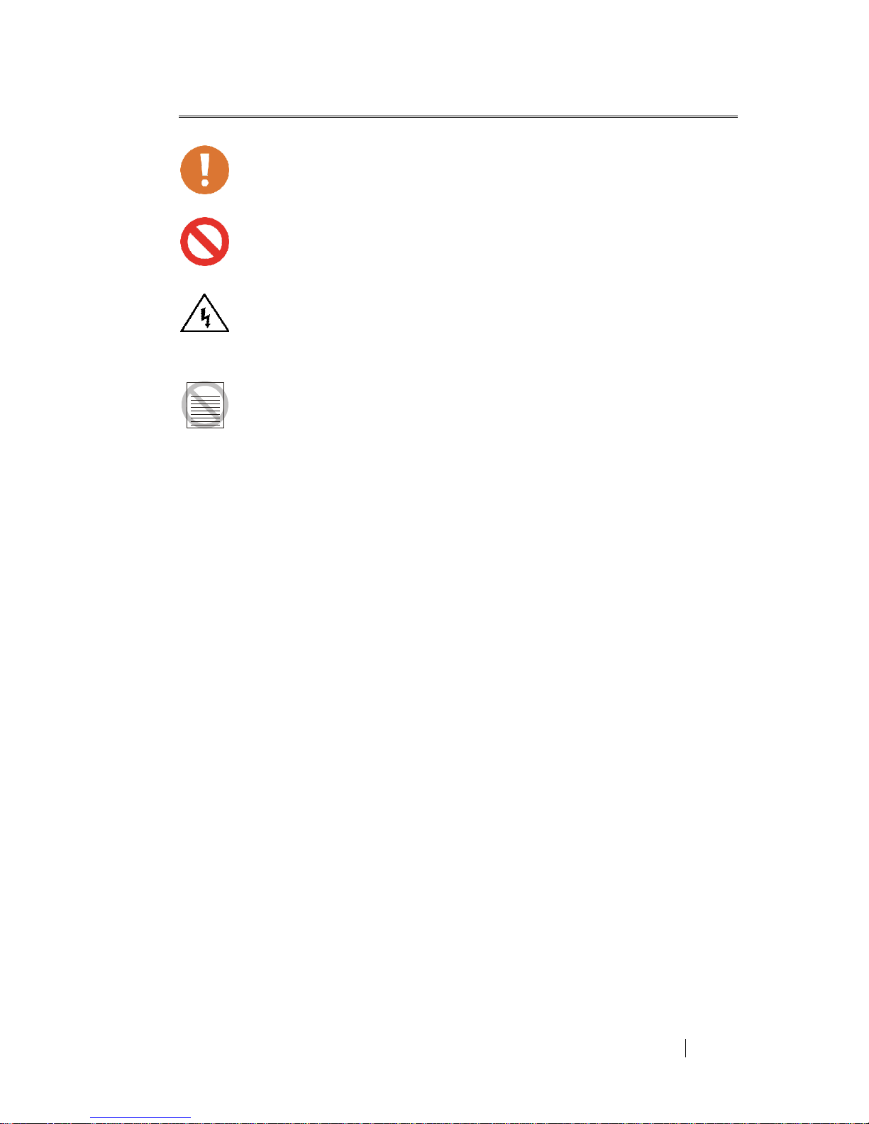
Note: Denotes helpful information intended to provide tips for better use of the
product.
CAUTION: Denotes a hazard. Failure to follow instructions could result in
minor personal injury and/or property damage. Included text gives proper
procedures.
WARNING: Denotes a hazard. Failure to follow instructions could result in
SEVERE personal injury and/or property damage. Included text gives
proper procedures.
Safety Information
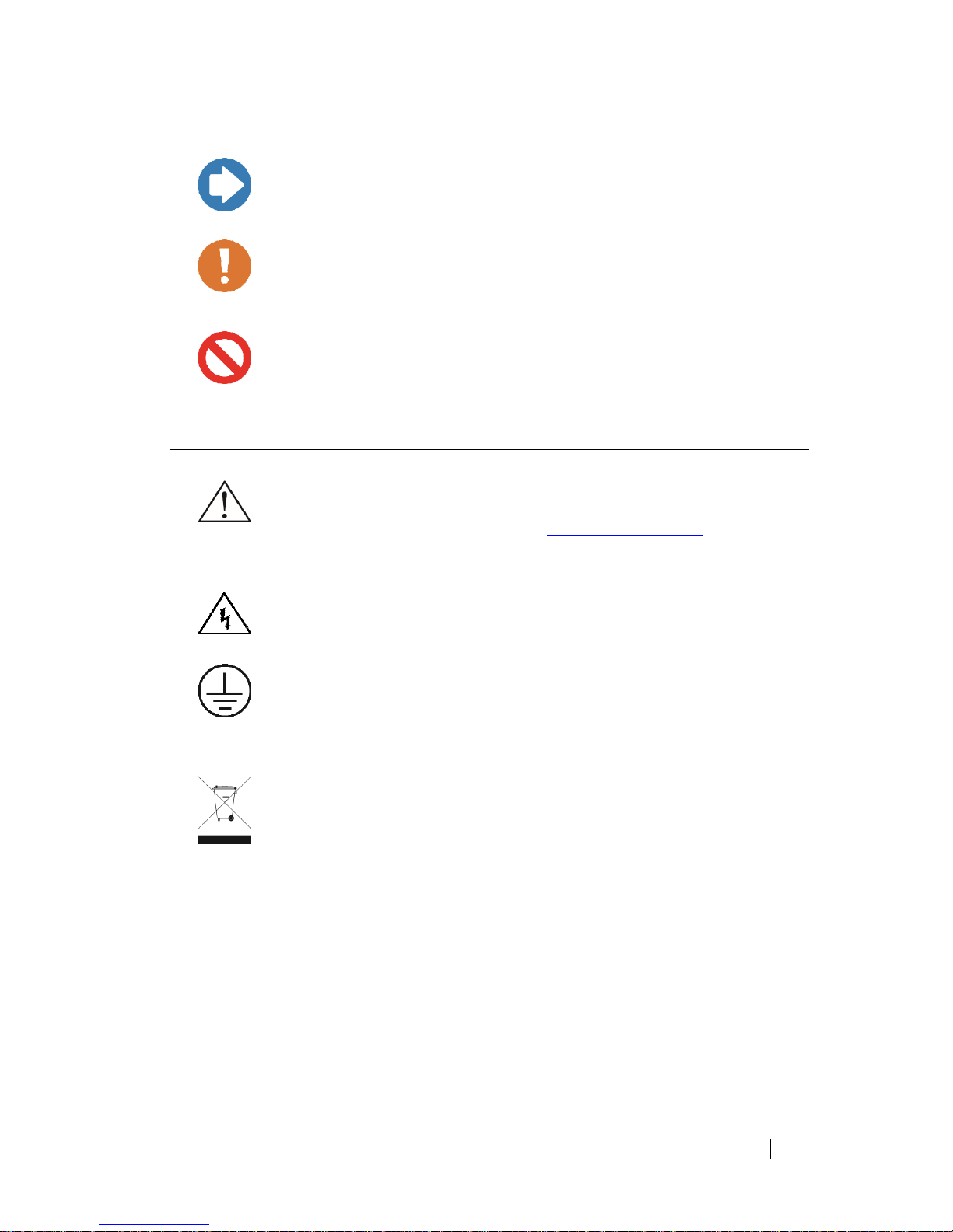
Refer to Manual: When product is marked with this symbol, see the
instruction manual for additional information. If the instruction manual
has been misplaced, download it from www.ets-lindgren.com, or contact
ETS-Lindgren Customer Service.
High Voltage: Indicates presence of hazardous voltage. Unsafe practice
could result in severe personal injury or death.
Protective Earth Ground (Safety Ground): Indicates protective earth
terminal. You should provide uninterruptible safety earth ground from the
main power source to the product input wiring terminals, power cord, or
supplied power cord set.
Waste Electrical and Electronic Equipment (WEEE) Directive: (European
Union) At end of useful life, this product should be deposited at an
appropriate waste disposal facility for recycling and disposal. Do not
dispose of with household waste.
Page 6

vi
www.ets-lindgren.com
This page intentionally left blank.
Page 7

www.ets-lindgren.com
Introduction
7
1.0 Introduction
The ETS-Lindgren Model 8100-007 RF Power Amplifier can deliver an output
power of 75 W over the frequency range of 1000 MHz to 2500 MHz and an output
power of 100 W over the frequency range of 2500 MHz to 6000 MHz.
The instrument consists of 2 different amplifier lineups, between which can be
switched via coaxial relays. Amplifier band 1 covers the frequency range of 1000 …
2500 MHz and amplifier band 2 covers the frequency range of 2500 … 6000 MHz.
The four-stage solid-state amplifier of frequency band 1 is of modular design and
integrated into two RF modules, both featuring a high linearity and a flat frequency
response.
The five-stage solid-state amplifier of frequency band 2 is also of modular design and
integrated into two RF modules, both featuring a high linearity and a flat frequency
response.
In order to achieve a stable output power, the bias of the amplifier stages are
controlled by low-drift voltage regulators.
The maximum input power for achieving the nominal output power is 0 dBm
corresponding to 1 mW or 0.224 V into 50 . Due to its gain reserve, the amplifier
usually achieves full output power with an input power of -5 dBm.
The final stage is separately protected against overload by current limitation. The
amplifier is protected against open circuit and short circuit at the output. By using
suitable transistors and a special circuit design in the final stage, even a total
mismatch at the output will not cause any damage. For a VSWR 2:1 the maximum
power can be obtained, all specifications being met.
The amplifier housing is designed to ensure minimum RF leakage and high RF
immunity. The module is supplied with DC voltage via RF feed through filters.
In order to protect the amplifier against thermal overload in case the blower fails or
the ambient temperature is too high, a temperature sensor is mounted on the heat
sink in the vicinity of the final stage.
Page 8
8
Introduction
www.ets-lindgren.com
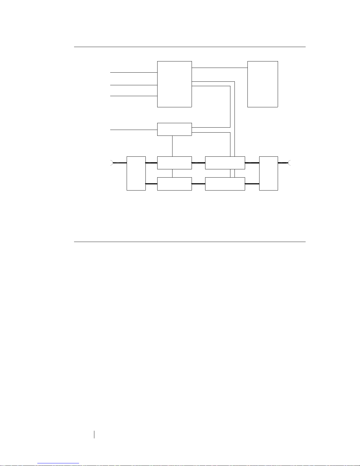
Standard Configuration
Figure 1: Amplifier block diagram
Optional Items
RACK MOUNT BRACKETS
Set of two brackets for fixing the amplifier in standard 19” racks.
Preamplifier Module 2 Final stage Module 2
+24V
RF switch
Remote Control and
Interlock Connector
IEEE Connector
+12V
Preamplifier Module 1
RF switch
Temperature Sense
Final stage Module 1
RF Input
Mains
Control Unit
Power Supply
+28V
RF Output
Keyboard Card
Ethernet Connector
Page 9
www.ets-lindgren.com
Maintenance
9
2.0 Maintenance
CAUTION: Before performing any maintenance, follow the information
provided in Safety Information on page v.
WARNING: Maintenance of this power amplifier is limited to external
components such as cables or connectors. If you have any questions
concerning maintenance, contact ETS-Lindgren Customer Service.
Clean the exterior of the cabinet using a damp cloth and mild cleaner.
Always unplug the unit before cleaning.
To prevent electrical shock, do not remove cover.
Warranty may be void if the housing is opened.
If you have any questions concerning maintenance, contact ETS-Lindgren
Customer Service.
WARRANTY
Page 10

10
Maintenance
www.ets-lindgren.com
Maintenance Recommendations
In general, the amplifier does not require any maintenance due to its solid-state
amplifier design and overrating of all components under thermal stress.
The fans have a lifetime 40,000 h; this results in a lifetime of 5 years even with
permanent operation.
Cleaning and care of the RF connectors are to be performed according to the
regulations valid for N-series connectors. All mechanical and electrical specifications
are guaranteed for at least 500 plug-in cycles.
Troubleshooting
If the green control light inside the mains switch does not light after turning mains on,
please check the following.
No response after switching Check the fuses at the line input at the rear
the mains switch on: panel of the amplifier.
Check the mains voltage at the mains
connector.
If a fault message will be displayed, the following should be checked:
Display: Interlock External Check the connection to the external
interlockswitch or jumper in the interlock
connector (see Figure 2 on page 17 and
Figure 3 on page 18).
Display: Temperature X Check whether the airflow is obstructed.
Check if the internal blower works.
Check if the ambient temperature is more than
+45 °C.
Allow the instrument to cool down and try to start
again.
Check if the Fault message persists.
Display: PowerSupply X Fault of one or more output voltages of the
indicated power supply X.
Switch off the amplifier and try to start again.
Check if the Fault message persists.
Display: Switch fault An internal switch error has occurred.
Switch several times between the frequency
bands.
Switch off the amplifier and try to start again.
Check if the Fault message persists.
Page 11

www.ets-lindgren.com
Maintenance
11
Display: TTL or GPIB or LAN Press the Control key until the display
indicates LOCAL. The amplifier can now be
activated locally.
If a non-permanent error message is being displayed it has to be confirmed by
pushing the Standby/Operate key at the front panel before the fault status will be
unlatched.
Page 12

12
Maintenance
www.ets-lindgren.com
Replacement and Optional Parts
Note: ETS-Lindgren may substitute a similar part or new part number with the
same functionality for another part/part number. Contact ETS-Lindgren for
questions about part numbers and ordering parts.
Service Procedures
CONTACTING ETS-LINDGREN
Note: Please see www.ets-lindgren.com for a list of ETS-Lindgren offices,
including phone and email contact information.
SENDING A COMPONENT FOR SERVICE
1. Contact ETS-Lindgren Customer Service to obtain a Service Request
Order (SRO).
2. Briefly describe the problem in writing. Give details regarding the
observed symptom(s) or error codes, and whether the problem is
constant or intermittent in nature. Please include the date(s), the service
representative you spoke with, and the nature of the conversation.
Include the serial number of the item being returned.
3. Package the system or component carefully. If possible, use the original
packing materials or carrying case to return a system or system
component to ETS-Lindgren.
CALIBRATION SERVICES
Annual Calibration—For reliable and repeatable long-term performance, annual
recalibration of your measuring device by an ETS-Lindgren experienced technician
is recommended. The ETS-Lindgren calibration team will calibrate most any type or
brand of measuring device. Additional information is available at
www.ets-lindgren.com/calibration.
Calibration Services Plus!™—Calibration Services Plus! is a customized, optional
program to help you expertly maintain your test and measurement assets. It is
designed to address the challenges of managing the calibration and repair of test
and measurement components, including scheduling and planning to ensure peak
performance. Additional information is available at
www.ets-lindgren.com/maintenance.
Page 13

www.ets-lindgren.com
Specifications
13
3.0 Specifications
Electrical Specifications
Frequency range
1000-6000 MHz
Output power
75 W cw min. (1000-2500 MHz)
50 W cw min. (2500-6000 MHz)
Gain
48.8 dB min. (1000-2500 MHz)
47.0 dB min. (2500-6000 MHz)
Input power
0 dBm max. to get nominal output power
+10 dBm max. for no damage
Harmonics
-15 dBc min. (2nd), -20 dBc min. (3rd)
Spurious
-50 dBc min.
AC supply
100 VAC to 240 VAC, ±10%
47 Hz to 63 Hz
Line power
500 VA
RF connectors (input/output)
N-f, on rear panel
Impedance (input/output)
50 Ohms
VSWR (input/output)
2:1 typ.
Load VSWR
Infinite for no damage
Remote control interfaces
GPIB, LAN, TTL
Physical Specifications
Dimensions (WxHxD)
430 mm x 133 mm(3 HU) x 630 mm
16.9 in x 5.2 in x 24.8 in
Weight
22.5 kg (50 lb)
Ambient temperature
0°C to +45°C (+32°F to +113°F)
Storage temperature
-20°C to +85°C (-4°F to +185°F)
Humidity
95% max. (non condensing)
Vibration and shock
Acc. MIL-STD 810F
Altitude
7000 ft above sea level
Page 14

14
Specifications
www.ets-lindgren.com
This page intentionally left blank.
Page 15

www.ets-lindgren.com
Before You Begin
15
4.0 Before You Begin
CAUTION: Before connecting any components, follow the information
provided in Safety Information on page v.
Setting up the Amplifier
When setting up the amplifier, make sure that the cooling airflow is impeded neither
at the air inlet at the front nor at the outlet at the rear. The permissible operating
temperature ranges from +0°C to +45°C with an air humidity of max. 95%. The outlet
air temperature exceeds the inlet temperature by max. 20°C.
CAUTION: The temperature of the inlet cooling air must not exceed
+45°C. The outlet air temperature should be maximum 20°C higher than
the inlet air temperature.
Rack Mounting
To ensure sufficient ventilation:
Make sure to provide enough space between the casing and the air inlet at
the front panel and the air outlet at the rear.
Make sure that there is sufficient air supply inside the rack (forced ventilation)
and that no overheating can occur due to other instruments placed under or
over the amplifier.
CAUTION: The temperature of the inlet cooling air must not exceed
+45°C.
Page 16

16
Before You Begin
www.ets-lindgren.com
This page intentionally left blank.
Page 17

www.ets-lindgren.com
Pre-Installation Tasks
17
5.0 Pre-Installation Tasks
CAUTION: Before connecting any components, follow the information
provided in Safety Information on page v.
Mains Connection
The amplifier is equipped with a power supply which can be operated at a voltage of
100–240 VAC. The automatic line fuse (12 A T) is integrated in the mains switch.
Note: When connecting the amplifier to the AC mains network, make sure to
provide a proper protective earth connection according to the regulations.
RF Connectors
The amplifier is equipped with N-type female connectors at all RF connectors. The
mating connectors must be tightened manually.
Interlock Safety Loop
This amplifier permits an interlock safety loop to be connected, which must be always
closed for activating the amplifier. The interlock function protects the user against
unintentional emission of RF power.
It is necessary to wire the attached mating connector for the Remote Control and
Interlock connector at the rear panel of the instrument as shown below. Pin 8 and pin
15 should be connected to the safety loop of the measuring room.
Figure 2: Pin assignment of remote control and interlock connector
This ensures that the amplifier can only be switched on when the safety switch, and
thus the door of the measuring room, is closed.
Page 18

18
Pre-Installation Tasks
www.ets-lindgren.com
The EXTERNAL INTERLOCK and EXTERNAL INTERLOCK RETURN contacts are
designed as floating ones. In this way more than one amplifier can be interconnected
in an interlock system with a common switch or a common loop.
Figure 3: Example of interlock safety loops
If this safety function is not used after thorough examination, the interlock contact can
be bridged in the Remote Control and Interlock connector. This is done using a
jumper from EXTERNAL INTERLOCK pin 8 to EXTERNAL INTERLOCK RETURN
pin 15.
Note: If the interlock connection is missing, the amplifier cannot be operated.
Finally, check that there is no message indicating an interlock error status on the
display. Now the amplifier is ready for use and can be operated either manually via
the front panel or via one of the remote control interfaces.
Page 19

www.ets-lindgren.com
Operation
19
6.0 Operation
CAUTION: Before placing into operation, follow the information provided
in Safety Information on page v.
Note: Make sure you are satisfied with the contents and condition of your
system prior to placing it into operation.
Front Panel View
Figure 4: Front panel view
1 STATUS LED LED is illuminated when a fault occurs,
which shuts down the amplifier
2 DISPLAY Status Display
Amplifier Status See chapter 6, Operation, on page 19
Fault Indications See chapter 2, Maintenance, on page 9
Type of amplifier Indication of amplifier model number
Elapsed time meter Indication of hours in operation
GPIB-Address Setting of the GPIB-address
3 STANDBY/OPERATE KEY Key for switching the amplifier on/off
Display: OPERATE RF switched on (amplifier active)
Display: STANDBY RF switched off (amplifier in standby)
1 2
M4
M4
M4
M4
Status
Standby
Operate
M5
M5
3 4
8100-007 RF Power Amplifier
1000 – 6000 MHz
Control
Band
Page 20

20
Operation
www.ets-lindgren.com
4 CONTROL/BAND KEY Key for switching to local control mode
Key for switching the amplifier band
Display: LOCAL Front panel control enabled
Display: GPIB IEEE 488.2 GPIB remote control enabled
Display: LAN Ethernet remote control enabled
Display: TTL TTL remote control enabled
Display: BAND x Band x is selected
Rear Panel View
Figure 5: Rear panel view
10 MAINS SWITCH Illuminated when mains is switched on
11 MAINS RECEPTABLE AC power plug
12 REMOTE CONTROL AND Connector for interlock loop and
INTERLOCK CONNECTOR the standard remote control interface
13 ETHERNET CONNECTOR Ethernet remote control interface
14 IEEE-CONNECTOR IEEE-488.2 GPIB interface connector
15 FANS
16 RF INPUT RF-input connector
17 RF OUTPUT RF-output connector
100-240 V AC
50/60 Hz 500 VA
F1/F2: IEC 127-2 / III-T 10 AT
Mains
1
0
1514
11 16
17 15
1012
IEEE 488.2
Remote Control
Interlock
Ethernet
Output
Input
NEUTRIK
NE8FDY-C6
Option Option
TM
SN 00163508
13
Page 21

www.ets-lindgren.com
Operation
21
Manual Operation
Press the MAINS switch to turn on the amplifier.
The MAINS switch is illuminated. Only the main control board is supplied and
the turn-on procedure of the instrument is executed.
The model number will be shown in the power up screen on the display
(Screen P).
After 2 seconds the amplifier will change the display to its main screen
(Screen M).
The amplifier is now in standby and in the local control mode
(Display:LOCAL).
In this state the amplifier offers a user menu, which allows viewing
miscellaneous diagnostic parameters of the instrument and allows adjusting
of the IEEE address.
The following description refers to Figure 6: User Menu on a page 23 which gives an
overview of the user menu pages:
From the main screen, the user menu can be accessed by pushing the left
and the right button simultaneously for at least one second.
The first page of the user menu is the voltage and current page (Screen V).
It is primarily intended for diagnostics (e.g. during checking or service)
and shows the actual voltage and current values of all the internal
power supply output channels of the instrument.
By clicking the left or right button the previous or next supply channel
can be monitored.
Exit the voltage and current page by pushing the left and the right
button simultaneously for at least one second.
The second page of the user menu is the amplifier identification screen
(Screen I).
This screen shows the type and serial number of the amplifier (same as
the remote control command “*IDN?” will respond).
Exit the amplifier identification page by pushing the left and the right
button simultaneously for at least one second.
Page 22

22
Operation
www.ets-lindgren.com
The third page of the user menu is the elapsed time meter screen (Screen E).
This screen shows the overall amount of time that the amplifier has
been in operation mode (OPERATE) and the amount of RF switch on
cycles. The display format is “Total Hours:Minutes:Seconds (Cycles)”.
You can change between the elapsed time meter for “Mains on”, the
elapsed time meter for “OPERATE” and (if applicable) the elapsed time
meters for “OPERATE in each frequency band” by pushing the right
button or the left button (to step back).
Exit the elapsed time meter page by pushing the left and the right
button simultaneously for at least one second.
The fourth screen of the user menu is the GPIB/IEEE address screen
(Screen G).
This screen allows viewing and changing of the current GPIB/IEEE
address of the amplifier.
The address is changed via clicking the left or right button.
The address ranges from 01 to 31 and the default address is 07.
Exit the GPIB/IEEE address page by pushing the left and the right
button simultaneously for at least one second.
After exiting the fourth user menu page the amplifier will show the main
screen (Screen M) again.
Page 23

www.ets-lindgren.com
Operation
23
Figure 6: User Menu
Screen P: Power Up
ETS Lindgren
8100-002
Screen M: Main
STANDBY BAND1 LOCAL
Screen V: Voltages
1A1 28.00V 4.50A ON
(-) Select 1A1 (+)
Screen I: Model identification
8100-002
00163509
Screen E: Elapsed time meters
Elapsed Time Mains
hhhhhh:mm:ss (ccccc)
Screen G: Set GPIB address
Set GPIB Address: 07
(-) (+)
Idle 120 sec.
Idle 10 sec.
Idle 10 sec.
Idle 10 sec.
= Push both buttons at least 1 sec.
3 sec.
Page 24

24
Operation
www.ets-lindgren.com
For safety reasons, the amplifier includes an interlock function as standard. Any
occurring error is indicated on the front panel in the display.
Note: The amplifier can not be activated from the front panel or via the remote
control interfaces as long as an interlock error is signaled.
Connect RF generator and RF power load to the amplifier using RF cables
(tighten connectors accordingly).
CAUTION: The maximum permissible input power is +10 dBm (0.707 V).
The amplifier already provides the nominal output power at typically
-5 dBm.
Press the CONTROL/BAND key to select the desired frequency band.
Band 1: 1000 ... 2500 MHz
Band 2: 2500 ... 6000 MHz
Press the Standby/Operate key.
The STANDBY text in the display changes to OPERATE.
If the interlock loop is interrupted during operation, the amplifier is
deactivated automatically. The error message Interlock External will be
displayed. If the door and thus the safety switch are closed again, the
amplifier is not activated again automatically but must be activated via
the front panel or via one of the remote control interfaces.
After a measurement has been concluded, the amplifier can be
deactivated by pressing the Amplifier key again. RF OFF will be shown
at the display. For removal of the internal heat the fan can be operating
for about one more minute.
CAUTION: If the amplifier is driven outside its frequency range, no
damage is caused; however, only the signal component (e.g. harmonics
of generator), which lies within the frequency range of the amplifier, is
amplified.
In this case, measuring the output power does not provide any
information on the actual operation of the instrument.
Page 25

www.ets-lindgren.com
Operation
25
Remote Control via the IEC/IEEE-488.2 GPIB Interface
The instrument is equipped with an IEC-Bus connection. The connector according to
IEEE 488 is located at the rear panel of the instrument. This interface can be used to
connect a controller for remote control purposes. The connection must be made using
a shielded cable.
Characteristics of the IEC/IEEE.2 GPIB interface:
8 bit parallel data transfer
Bidirectional data transfer
Three wire handshake
High data transfer rate
Up to 15 instruments can be connected
Maximum length of interconnection cables 15 m (each single connection 2 m)
DI/0
DI/0
2
4
IFC
NDAC
EOI
1
DI/0
DI/0
DI/0
3
NRFD
DAV
123 4
13 14 15 16
5 6 7
8
171819
20
SHIELD
ATN
SRQ
91011 12
21 22 23 24
9
GND
GND
DI/0
DI/0 GND
REN
5
6
DI/0
7
8
7
GND
6 8
LogicGND
GND
11
10 GND
Figure 7: Pin assignment of IEEE connector
On power on, the amplifier is always in the local state (manual operation). At the front
panel display LOCAL will be indicated.
If a controller addresses the amplifier as a listener by sending the REMOTE
command, the amplifier changes to the remote state and remains in this state even
after termination of data transmission. This is indicated by the message GPIB at the
front panel display.
A change of the control mode is only possible when the amplifier is in STANDBY
mode.
Page 26

26
Operation
www.ets-lindgren.com
There are two methods to return to the local state:
By the controller command "Go To Local" (GTL).
By pressing the Control key on the front panel of the amplifier.
SETTING THE GPIB INSTRUMENT ADDRESS
The IEEE bus address (GPIB address) of the amplifier will be shown and can be
changed within the user menu. Please refer to page 22 for details.
The valid address range is from 01 to 31. Other settings are not permissible. The
address set is immediately taken over after an alteration.
Upon delivery of the instrument, address 07 is set.
INTERFACE MESSAGES
Interface messages are transferred by the controller to a device via eight data lines,
the ATN line remaining active, i.e. low. Only an active controller is able to issue
interface messages. A distinction is made between universal commands and
addressed commands.
Universal commands are effective for all the devices connected to the IEEE-488
GPIB-bus without previous addressing.
Command
Function
DCL
(Device Clear)
Aborts processing of the currently received commands and
resets the command processing software to a defined initial
status. This command does not affect the device settings.
Figure 8: IEEE universal commands
Addressed commands act only on devices that have been addressed as listeners by
the controller before.
Command
Function
SDC
(Selected Device
Clear)
Aborts processing of the currently received commands and
resets the command processing software to a defined initial
status. This command does not affect the device settings.
*RST
Reset
Figure 9: IEEE addressed commands
A device remains addressed to listen until it is unaddressed by the controller.
Page 27

www.ets-lindgren.com
Operation
27
Control Characters
Numbers and
Characters
Upper-case letters
Lower-case letters
0
Nul 16
DLE 32
SP
48 0 64 @ 80 P 96 ` 112
p
1
SOH
17
DC1 33 ! 49 1 65 A 81 Q 97 a 113
q
2
STX 18
DC2 34 ~ 50 2 66 B 82 R 98 b 114
r
3
ETX 19
DC3 35 # 51 3 67 C 83 S 99 c 115
s
4
EOT
SDC
20
DC4
DCL
36 $ 52 4 68 D 84 T 100 d 116
t
5
ENQ
21
NAK 37 % 53 5 69 E 85 U 101 e 117
u
6
ACK 22
SYN 38 & 54 6 70 F 86 V 102 f 118
v
7
BEL 23
ETB 39 ´ 55 7 71 G 87 W 103 g 119
w
8
BS 24
CAN
40 ( 56 8 72 H 88 X 104 h 120
x
9
HT 25
EM 41 ) 57 9 73 I 89 Y 105 i 121
y
10
LF 26
SUB 42 * 58 : 74 J 90 Z 106 j 122
z
11
VT 27
ESC 43 + 59 ; 75 K 91 [ 107 k 123
{
12
FF 28
FS 44 , 60 < 76 L 92 \ 108 l 124
|
13
CR 29
GS 45 - 61 = 77 M 93 ] 109 m 125
}
14
SO 30
RS 46 . 62 > 78 N 94 ^ 110 n 126
¯
15
SI 31
US 47 / 63
?/UNL
79 O 95 - 111 o 127
DEL
Addressed
Commands
Universal
Commands
Listener Address
Talker Address
Secondary Addresses
and Commands
Figure 10: ASCII/ISO and IEC character set
DEVICE MESSAGES
Device messages (to IEC 625-1) are transmitted on the data lines, in which case the
ATN line is not active, i.e. high. The ASCII code (ISO 7-bit code) is used.
Commands Received by the Amplifier in Listener Mode
(Controller to Device Messages)
The ASCII code (ISO 7-bit code) is used. All commands to the amplifier
consist of a single character set followed by the "Line feed" character
(hexadecimal: 0A; decimal: 10) as a terminator.
All commands to the amplifier must be terminated by a terminator. The only
permissible terminator is:
<Line feed> (ASCII code 10 decimal)
A command line may require more than one line on the screen of the
controller because it is only limited by the terminator. Most controllers
automatically append a terminator to the transmitted data.
Page 28

28
Operation
www.ets-lindgren.com
The following command sequences result from this:
Function
Command (String)
Go to remote
REMOTE
Go to local
LOCAL
Amplifier on (Operate)
AMP_ON
Amplifier off (Standby)
AMP_OFF
Select Band 1
SW01_1
Select Band 2
SW01_2
Poll of switch position
SW01?
Amplifier on/off status
AMP?
Amplifier identification
*IDN?
Amplifier reset
*RST
Control status
CONTROL?
Figure 11: IEEE interface commands
Messages Sent by the Amplifier in Talker Mode
(Device to Controller Messages)
The amplifier transmits messages via the IEEE-488.2 GPIB-bus if it has been
requested by a query command to provide data in its output buffer and has
been addressed as talker.
Note that the command line with the data requests must be transmitted
immediately before addressing as talker. The output buffer is cleared if
another command line is entered in between.
Transferring the Device Status
The status messages of the amplifier indicated at the display on the front
panel are transferred as a text via the IEEE-488.2 GPIB interface to the
controller. For this purpose, the status text must be polled first (see control
character sequence above). The text can then be transmitted in a standard
reading process. The amplifier transfers the text also with "Line feed" as the
terminator.
Page 29

www.ets-lindgren.com
Operation
29
The status messages indicated on the front panel are encoded in the status text
according to the following table:
Query
Status message (String)
Meaning
*IDN?
ETS, 8100-007, xxx
Instrument identification: Manufacturer, Model number,
Serial number
AMP?
AMP_ON
Amplifier is set to operate mode
AMP_OFF
Amplifier is set to standby mode
CONTROL?
LOCAL
Amplifier is in local control mode
GPIB
Amplifier is in GPIB control mode
LAN
Amplifier is in LAN control mode
TTL
Amplifier is in TTL control mode
SW01?
SW01_1
Switch in position Band 1
SW01_2
Switch in Position Band 2
STATUS?
SYSTEM_OK
Amplifier is working normally
Interlock External
External Interlock fault
Temperature X
Over temperature fault at sensor X
PowerSupply X
Power supply fault at output X
Switch Fault
Switch not in correct position
Control Fault
Internal control fault
Figure 12: IEEE interface status messages
Alarms
If a fault status occurs, the amplifier indicates the specific fault message and
sends a service request via the IEEE interface. The controller is able to
recognize this alarm message without having to poll the status byte of the
amplifier repeatedly.
To reset the fault message the command *RST has to be sent to the
amplifier.
The alarm message has to be acknowledged by way of the serial poll
procedure specified in the IEEE-488.2 GPIB standard (see interface manual
of the controller). The status byte issued by the amplifier corresponds to the
above-mentioned status messages.
Page 30

30
Operation
www.ets-lindgren.com
Remote Control via the Ethernet Interface
The instrument is equipped with a LAN interface. The RJ45 connector is located at
the rear panel of the instrument. This interface can be used to connect a controller for
remote control purposes. The connection must be made using a shielded cable.
RJ-45-Connector female (EIA/TIA 568A)
1
TX+
Transmitted data high
2
TX-
Transmitted data low
3
RX+
Receive data high
4 (not used)
5 (not used)
6
RX-
Receive data high
7 (not used)
8 (not used)
Figure 13: Pin configuration of the Ethernet interface
On power on, the amplifier is always in the local state (manual operation). At the front
panel display LOCAL will be indicated.
If a controller addresses the amplifier as a listener by sending the REMOTE
command, the amplifier changes to the remote state and remains in this state even
after termination of data transmission. This is indicated by the message LAN at the
front panel display.
A change of the control mode is only possible when the amplifier is in STANDBY
mode.
There are two methods to return to the local state:
By the command LOCAL.
By pressing the Control key on the front panel of the amplifier.
Page 31

www.ets-lindgren.com
Operation
31
ADMINISTRATION BY LAN
Default IP Address of the Ethernet Interface is 192.168.1.253
The Ethernet interface can be configured for the first time by LAN only if the
client computer / local network is matching this address range and subnet
mask. Only one new Ethernet interface can be plugged on the LAN at a given
time, until an individual IP address is assigned on each Ethernet interface;
otherwise, conflicts will be caused.
Computer Configuration
Configure computer with:
IP address 192.168.1.xxx where xxx = 253, and
subnet mask 255.255.255.0 are assigned by default.
Check that computer is connected to same Ethernet LAN than the Ethernet
interface.
TCP/IP Configuration
IP address of each Ethernet interface must be unique on the network. An
individual address can be either assigned by:
A static address using administrative commands, or
An existing DHCP server on the network, who can assign an available
address.
If both DHCP and static IP address are defined, DHCP configuration will
override static IP.
TCP/IP Configuration Setup
Open web browser.
Enter IP address of Ethernet interface (e.g. http://192.168.1.253).
Enter user and password (8 digits), default user ”user” default password
"admin00", and the following page will display:
Page 32

32
Operation
www.ets-lindgren.com
Select "Status" to get basic information about the actual amplifier status.
Then the following page will display:
Page 33

www.ets-lindgren.com
Operation
33
Select "Network- and Password-Settings", and the following page will display:
Page 34

34
Operation
www.ets-lindgren.com
Set IP address, network mask, gateway or alternatively select DHCP and confirm
settings by "OK".
The system will return to the previous page (“Device Commands”) from where the
instrument can be fully controlled.
Page 35

www.ets-lindgren.com
Operation
35
ETHERNET CONTROL COMMANDS
The ASCII code (ISO 7-bit code) according to Figure 10 of this manual is used. All
commands to the amplifier consist of a single character set followed by the "Line
feed" character (hexadecimal: 0A; decimal: 10) as a terminator.
All commands to the amplifier must be terminated by a terminator. The only
permissible terminator is:
<Line feed> (ASCII code 10 decimal)
Between each two commands there should be a delay time of 200 ms to avoid a
command overflow situation.
The following command sequences result from this:
Function
Command (String)
Go to remote
REMOTE
Go to local
LOCAL
Amplifier on (Operate)
AMP_ON
Amplifier off (Standby)
AMP_OFF
Select Band 1
SW01_1
Select Band 2
SW01_2
Poll of switch position
SW01?
Amplifier on/off status
AMP?
Amplifier identification
*IDN?
Amplifier reset
*RST
Control status
CONTROL?
Amplifier status
STATUS?
Figure 14: Ethernet interface commands
Page 36

36
Operation
www.ets-lindgren.com
STATUS MESSAGES OF THE AMPLIFIER IN ETHERNET REMOTE CONTROL MODE
The amplifier will return a status information if it is requested to do so by a data poll
command.
The status messages which are indicated on the front panel display can also be
transmitted as status information via the Ethernet remote control interface to the
control computer.
The status messages indicated on the front panel are encoded in the status text
according to the following table:
Query
Status message (String)
Meaning
*IDN?
ETS, 8100-007, xxx
Instrument identification: Manufacturer, Model number,
Serial number
AMP?
AMP_ON
Amplifier is set to operate mode
AMP_OFF
Amplifier is set to standby mode
CONTROL?
LOCAL
Amplifier is in local control mode
GPIB
Amplifier is in GPIB control mode
LAN
Amplifier is in LAN control mode
TTL
Amplifier is in TTL control mode
SW01?
SW01_1
Switch in position Band 1
SW01_2
Switch in Position Band 2
STATUS?
SYSTEM_OK
Amplifier is working normally
Interlock External
External Interlock fault
Temperature X
Over temperature fault at sensor X
PowerSupply X
Power supply fault at output X
Switch Fault
Switch not in correct position
Control Fault
Internal control fault
Figure 15: Ethernet interface status messages
Page 37

www.ets-lindgren.com
Operation
37
Remote Control and Interlock Interface
Pin
Signal
Function
1
MAINS ON (100 mA)
Status (CMOS, 12 V = Mains on)
2
OPERATE
Status (CMOS, 12 V = OPERATE)
3
n.u.
Status
4
n.u.
Status
5
TTL REMOTE
Status (CMOS, 12 V = Remote)
6
SUMMARY ALARM
Status (CMOS, 12 V = Fault)
7
GND
8
EXTERNAL INTERLOCK
9
OPERATE
Command (negative slope triggered)
10
n.u.
Command (negative slope triggered)
11
TTL REMOTE
Command (negative slope triggered)
12
n.u.
Command (negative slope triggered)
13
n.u.
14
GND
15
EXTERNAL INTERLOCK RETURN
Figure 16: Signals at the remote control and interlock connector
All commands and messages, which are available on the front panel, can also be
found on the remote control interface. The status messages for all faults are
combined to a summary alarm on the interface.
The remote control interface commands are activated by negative slope triggering.
(The pulse width should be 10 to 50 ms.) This is done in order not to activate the
amplifier immediately on power-on by static remote control interface commands (TTL
REMOTE and OPERATE). Triggering on the negative slope permits to control the
interface by 12 V CMOS logic or 5 V open-collector TTL logic.
The status output MAINS ON supplies a maximum current of 100 mA at 12 V in order
to be able to activate and feed other equipment, or, for example, an external interface
and similar devices together with the amplifier.
The amplifier can be set to remote control mode and back to local control mode by
using the command TTL REMOTE. At the status display the text will change from
LOCAL to TTL. Now the amplifier can be activated using the command OPERATE.
The indicated message must then change accordingly from STANDBY to OPERATE.
Page 38

38
Operation
www.ets-lindgren.com
This page intentionally left blank.
Page 39

www.ets-lindgren.com
Warranty
39
Appendix A: Warranty
Scope and Duration of Warranties
Seller warrants to Buyer that the Products to be delivered hereunder will be (1) free
from defects in material, manufacturing workmanship, and title, and (2) conform to the
Seller’s applicable product descriptions and specifications, if any, contained in or
attached to Seller’s quotation. If no product descriptions or specifications are
contained in or attached to the quotation, Seller’s applicable product descriptions and
specifications in effect on the date of shipment shall apply. The criteria for all testing
shall be Seller’s applicable product specifications utilizing factory-specified calibration
and test procedures and instruments.
All product warranties, except the warranty of title, and all remedies for warranty
failures are limited to three years.
Product Warranted
Duration of Warranty Period
Model 8100-007 RF Power Amplifier
Three Years
Any product or part furnished to Buyer during the warranty period to correct a
warranty failure shall be warranted to the extent of the un expired term of the
warranty applicable to the repaired or replaced product.
The warranty period shall commence on the date the product is delivered to Buyer;
however, if Seller assembles the product, or provides technical direction of such
assembly, the warranty period for such product shall commence on the date the
assembly of the product is complete. Notwithstanding the foregoing, in the event that
the assembly is delayed for a total of thirty (30) days or more from the date of delivery
for any reason or reasons for which Seller is not responsible, the warranty period for
such product may, at Seller’s options, commence on the thirtieth (30th) day from the
date such product is delivered to Buyer. Buyer shall promptly inspect all products
upon delivery. No claims for shortages will be allowed unless shortages are reported
to Seller in writing within ten (10) days after delivery. No other claims against Seller
will be allowed unless asserted in writing within thirty (30) days after delivery (or
assembly if the products are to be assembled by Seller) or, in the case of alleged
breach of warranty, within the applicable warranty period.
Page 40

40
Warranty
www.ets-lindgren.com
Warranty Exclusions
Except as set forth in any applicable patent indemnity, the foregoing warranties are
exclusive and in lieu of all other warranties, whether written, oral, express, implied, or
statutory. EXCEPT AS EXPRESSLY STATED ABOVE, SELLER MAKES NO
WARRANTY, EXPRESS OR IMPLIED, BY STATUTE OR OTHERWISE, WHETHER
OF MERCHANTABILITY OR FITNESS FOR ANY PARTICULAR PURPOSE OR USE
OR OTHERWISE ON THE PRODUCTS, OR ON ANY PARTS OR LABOR
FURNISHED DURING THE SALE, DELIVERY OR SERVICING OF THE
PRODUCTS. THERE ARE NO WARRANTIES WHICH EXTEND BEYOND THE
DESCRIPTION ON THE FACE HEREOF.
Warranty coverage does not include any defect or performance deficiency (including
failure to conform to product descriptions or specifications) which results, in whole or
in part, from (1) negligent storage or handling of the product by Buyer, its employees,
agents, or contractors, (2) failure of Buyer to prepare the site or provide an operating
environmental condition in compliance with any applicable instructions or
recommendations of Seller, (3) absence of any product, component, or accessory
recommended by Seller but omitted at Buyer’s direction, (4) any design, specification,
or instruction furnished by Buyer, its employees, agents or contractors, (5) any
alteration of the product by persons other than Seller, (6) combining Seller’s product
with any product furnished by others, (7) combining incompatible products of Seller,
(8) interference with the radio frequency fields due to conditions or causes outside the
product as furnished by Seller, (9) improper or extraordinary use of the product, or
failure to comply with any applicable instructions or recommendations of Seller
including maintenance, calibration and cleaning procedures and intervals, or (10) acts
of God, acts of civil or military authority, fires, floods, strikes or other labor
disturbances, war, riot, or any other causes beyond the reasonable control of Seller.
This warranty does not include (1) batteries, (2) cables, (3) gasket, (4) fingerstock, or
any item that is designed to be consumable. Seller does not warranty products of
others which are not included in Seller’s published price lists.
Buyer’s Remedies
If Seller determines that any product fails to meet any warranty during the applicable
warranty period, Seller shall correct any such failure by either, at its option, repairing,
adjusting, or replacing without charge to Buyer any defective or nonconforming
product, or part or parts of the product. Seller shall have the option to furnish either
new or exchange replacement parts or assemblies.
Warranty service shall be performed at the Seller’s factory, or the Buyer’s site at the
sole discretion of the Seller. Within the warranty period, the Buyer shall be
responsible for all transportation to the Seller’s factory, and the Seller shall be
responsible for transportation of goods to the Buyer’s site.
Page 41

www.ets-lindgren.com
Warranty
41
Within the contiguous 48 United States, warranty service performed during the
applicable warranty period will be performed without charge to Buyer during Seller’s
normal business hours. After the warranty period, service will be performed at Seller’s
prevailing service rates. Subject to the availability of personnel, after-hours service is
available upon request at an additional charge.
Outside the contiguous 48 United States, travel and per diem expenses, when
required, shall be the responsibility of the Buyer, or End User, whichever is applicable
regardless of the warranty period.
The remedies set forth herein are conditioned upon Buyer promptly notifying Seller
within the applicable warranty period of any defect or non-conformance and making
the product available for correction.
The preceding paragraphs set forth Buyer’s exclusive remedies and Seller’s sole
liability for claims based on failure of the products to meet any warranty, whether the
claim is in contract, warranty, tort (including negligence and strict liability) or
otherwise, and however instituted, and, upon the expiration of the applicable warranty
period, all such liability shall terminate. IN NO EVENT SHALL SELLER BE LIABLE
TO BUYER FOR ANY SPECIAL, INDIRECT, INCIDENTAL OR CONSEQUENTIAL
DAMAGES OF ANY KIND ARISING OUT OF, OR AS A RESULT OF, THE SALE,
DELIVERY, NON-DELIVERY, SERVICING, ASSEMBLING, USE OR LOSS OF USE
OF THE PRODUCTS OR ANY PART THEREOF, OR FOR ANY CHARGES OR
EXPENSES OF ANY NATURE INCURRED WITHOUT SELLER’S WRITTEN
CONSENT DESPITE ANY NEGLIGENCE ON BEHALF OF THE SELLER. IN NO
EVENT SHALL SELLER’S LIABILITIES UNDER ANY CLAIM MADE BY BUYER
EXCEED THE PURCHASE PRICE OF THE PRODUCT IN RESPECT OF WHICH
DAMAGES ARE CLAIMED. This agreement shall be construed in accordance with
laws of the State of Texas. In the event that any provision hereof shall violate any
applicable statute, ordinance, or rule of law, such provision shall be ineffective to the
extent of such violation without invalidating any other provision hereof.
Any controversy or claim arising out of or relating to the sale, delivery, non-delivery,
servicing, assembling, use or loss of use of the products or any part thereof or for any
charges or expenses in connection therewith shall be settled in Austin, Texas by
arbitration in accordance with the Rules of the American Arbitration Association, and
judgment upon the award rendered by the Arbitrator may be entered in either the
Federal District Court for the Western District of Texas or the State District Court in
Austin, Texas, all of the parties hereto consenting to personal jurisdiction of the venue
of such court and hereby waive the right to demand a jury trial under any of these
actions.
Page 42

42
Warranty
www.ets-lindgren.com
This page intentionally left blank.
Page 43

www.ets-lindgren.com
EC Declaration of Conformity
43
Appendix B: EC Declaration of Conformity
ETS-Lindgren Inc. declares these products to be in conformity with the following
standards, following the provisions of EMC Directive 2004/108/EC and Low Voltage
Directive 2006/95/EC:
RF Power Amplifier Model 8100-007
Emission:
EN 61326-1:2006, Class A
Electrical equipment for measurement, control, and laboratory use.
Note: Conducted emission complies with Class B
(household equipment).
Immunity:
EN 61326-1:2006, Industrial level, performance criteria A
Electrical equipment for measurement, control, and laboratory use.
Safety:
EN 61010-1:2010
Safety requirements for electrical equipment for measurement, control,
and laboratory use.
Technical Construction Files are available upon request.
Page 44

44
EC Declaration of Conformity
www.ets-lindgren.com
This page intentionally left blank.
 Loading...